Universalmodul UM-Cat.6A isoMontageanleitung / Installation instructions
Intended use
Important Note!
The connecting hardware starting from Category 6 is a highly sophisticated electrical and mechanical connection system for transmission band widths up to 500 MHz. They fulfil the current standards for the design as well as the transmission technique and the corresponding internation-al directives to its entirety.
Use this first-quality high-frequency connecting system with required care and note the following hints:
· For other connector models than RJ45, use an appro-priate adapter (i. e. ADAP Kombi 154 006 05).
· Only use patch cables and connectors that corre-spond to the valid EN/IEC standards. Ask your manu-facturer for a confirmation, if necessary.
· Avoid unnecessary, mechanical stress of the outlets caused by pull or pressure stress of the connector when inserting/removing patch cables or tilting.
· Lead the patch cables in the cabinet so that improper pressure to the plugs/ports is avoided when the door is closed.
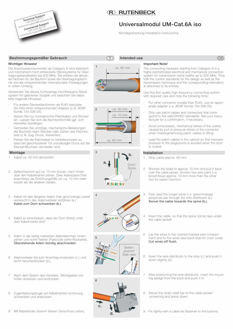
Installation1 Strip cable approx. 60 mm.
2 Shorten the braid to approx. 10 mm and pull it back over the cable jacket, shorten two wire pairs (i. e. brown/blue) approx. 10 mm more than the other two for easier insertion.
3 First, lead the longer wires (i. e. green/orange) perpendicular through the wire distributor (a.) Swivel the cable towards the spine (b.).
4 Insert the cable, so that the spine (circle) lays under the cable jacket!
5 Lay the wires in the colored marked wire compart-ment and fix the wires (see back side for color code). Cut wires off flush.
6 Insert the wire distributor to the stop (c.) and push it down slightly (d.).
7 After positioning the wire distributor, insert the mount-ing wedge from the back and push it in.
8 Swivel the strain relief bar to the cable jacket/ -screening and press down.
9 Fix tightly with a cable tie (fastener to the buttom).
Bestimmungsgemäßer Gebrauch
Wichtiger Hinweis!
Die Anschlusskomponenten ab Category 6 sind elektrisch und mechanisch hoch entwickelte Stecksysteme für Über-tragungsbandbreiten bis 500 MHz. Sie erfüllen die aktuel-len Normen für die Bauform sowie die Übertragungstech-nik und die entsprechenden internationalen Festlegungen in vollem Umfang.
Verwenden Sie dieses hochwertige Hochfrequenz-Steck-system mit gebotener Sorgfalt und beachten Sie dabei bitte folgende Hinweise:
· Für andere Steckerbauformen als RJ45 benutzen Sie bitte einen entsprechenden Adapter (z. B. ADAP Kombi 154 006 05).
· Setzen Sie nur normgerechte Patchkabel und Stecker ein. Lassen Sie sich die Normkonformität ggf. vom Hersteller bestätigen.
· Vermeiden Sie unnötige, mechanische Belastungen der Buchsen beim Stecken oder Ziehen des Patchka-bels (z. B. Zug, Druck, Verkanten).
· Führen Sie die Patchkabel im Verteilerschrank so, dass bei geschlossener Tür unzulässiger Druck auf die Stecker/Buchsen vermieden wird.
Montage1 Kabel ca. 60 mm abmanteln.
2 Geflechtschirm auf ca. 10 mm kürzen, nach hinten über den Kabelmantel ziehen. Zwei Adernpaare (hier braun/blau) als Einführungshilfe um ca. 10 mm mehr kürzen als die anderen beiden.
3 Kabel mit den längeren Adern (hier grün/orange) zuerst senkrecht in den Adernverteiler einführen (a.) Kabel zum Dorn schwenken (b.)
4 Kabel so einschieben, dass der Dorn (Kreis) unter dem Kabelmantel sitzt!
5 Adern in die farbig markierten Adernklemmen hinein-ziehen und somit fixieren (Farbcode siehe Rückseite). Überstehende Adern bündig abschneiden.
6 Adernverteiler bis zum Anschlag einstecken (c.) und leicht herunterdrücken (d.).
7 Nach dem Setzen des Verteilers Montagekeil von hinten einsetzen und eindrücken.
8 Zugentlastungsbügel auf Kabelmantel/-schirmung schwenken und andrücken.
9 Mit Kabelbinder stramm fixieren (Verschluss unten).
Technical Support
+49 2355 82-111
Commercial Support
+49 2355 82-137
1 ca. 60 mm
2
ca. 60 mm
ca. 50 mm
ca. 10 mm
3
a.Dorn/Spine
b.
4
5
Seiten- ansicht/
Side view
6
c.
d.

Montage (Fortsetzung) Installation (Continued)
10 Zur Demontage - Kabelbinder lösen - Zugentlastungsbügel nach oben schwenken - Montagekeil herausziehen - Kabelverteiler mit Schraubendreher anhebeln und
herausnehmen (e., f., g.)
Farbcode
Unsachgemäße NutzungBei Verwendung nicht normgerechter Anschlusskomponenten oder unsachgemäßer Nutzung des Moduls müssen wir von einer Anerken-nung des Mängelrechts oder anderen Garantiezusagen unseres Hau-ses Abstand nehmen. Bitte weisen Sie auch den Endnutzer auf diesen Sachverhalt hin.
CE-ErklärungWir, die Wilhelm Rutenbeck GmbH & Co. KG erklären in unserer alleinigen Verantwortung, dass sich dieses Gerät in Überein-stimmung mit den grundlegenden Anforderungen und relevan-ten Vorschriften der zutreffenden EU-Richtlinien 2014/35/EU, 2011/65/EU) befindet.
Die vollständige CE-Konformitätserklärung finden Sie unter www.rutenbeck.de im Download-Bereich.
EntsorgungDas nebenstehende Symbol weist auf die getrennte Sammlung von Elektro- und Elektronikgeräten hin. Dieses Gerät sowie alle im Lieferumfang enthaltenen Elektronikteile dürfen gemäß euro-päischer Richtlinien und deutschem Elektro- und Elektronikge-setz nicht über den Hausmüll entsorgt werden.
Bringen Sie dieses Gerät nach Ende seiner Nutzung zu einem zuständigen Sammelsystem für elektrische und elektronische Altgeräte.
Klagebach 33D-58579 SchalksmühleTelefon +49-(0) 23 55-82-0Telefax +49-(0) 23 55-82-105
© Wilhelm Rutenbeck GmbH & Co. KG · Technische Änderungen vorbehalten/Subjected to technical changes · 293 579 · 139 003 04 · Rut071 · Stand/Status 08.18
10 For disassembly - Loosen cable tie - Swivel the strain relief bar to top - Pull out mounting wedge - Use a screw driver to lif t up the wire distributor, take
it out (e., f., g.)
Color Code
Faulty useWhen using non-standard connecting hardware (i. e. patch cables or connectors) or at inappropriate use of the module we will not accept any warranty claims.
Please, inform the end-user about this issue.
CE - Declaration of confirmityWe, Wilhelm Rutenbeck GmbH & Co. KG, declare under our sole responsibility that this device is in conformity with the essen-tial requirements and the relevant regulations of the applicable EU-directives (2014/35/EU, 2011/65/EU).
The complete Declaration of Conformity is available in the Down-load Section at www.rutenbeck.com
DisposalThe adjacent symbol indicates separate waste collection for electrical and electronic devices. In accordance with EU-direc-tives, all electrical and electronic devices with this symbol must be disposed in the corresponding separate waste collections and not in the domestic waste.
This device as well as all the electronic parts included in the deliv-ery may not be disposed in the regular household waste but must be brought to a competent collection site after end of its use.
Anschlussklemme/ Terminalblock
TIA/EIA-568-A
TIA/EIA-568-B
1 2 3 4 5 6 7 8
7 8 9
10
g.
e.
f.


