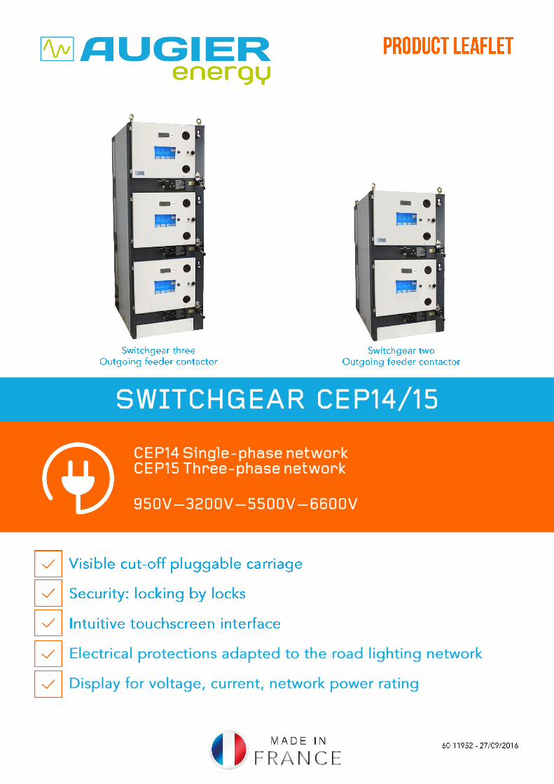
SWITCHGEAR CEP14/15
CEP14 Single-phase network CEP15 Three-phase network
950V—3200V—5500V—6600V

2
3
SWITCHGEAR MODELS CEP 14 / 15
SUMMARY
GENERAL INTRODUCTION ................................................................................................. 4 - 5
FIELD OF APPLICATION, STANDARDS ................................................................................. 5
RANGE OF SWITCHGEARS ....................................................................................................... 6
EXAMPLE OF CONFIGURATION ............................................................................................. 7
SWITCHGEAR CHARACTERISTICS .................................................................................. 8 - 14
ELECTRICAL CHARACTERISTICS ........................................................................................ 16
ELECTRICAL CIRCUIT DIAGRAM ......................................................................................... 17
DIMENSIONS and WEIGHTS ................................................................................................... 18
CABLE ROUTING ....................................................................................................................... 19
LOCKING and SAFETY ....................................................................................................... 20 - 21
LOW-VOLTAGE CABINET ........................................................................................................ 22
SERVICE and TRAINING .......................................................................................................... 23

4
Introduction
Work with a French manufacturer
Global references
Quality Assurance
Technical Support
A range of compatible switchgears
Safe and secure to use
Compatible with existing switchgear
Compact
Examples of applications
Since 1973, AUGIER has been designing and
manufacturing a range of CEP switchgears at its
production facility in Carros, France.
CEP switchgears are installed worldwide on lighting
applications and other load demands. A detailed list of
references is available on request.
AUGIER is ISO 9001 certified since 1995.
The implementation of quality checks with these
switchgears calls for:
Stringent checks at every stage of the manufacturing
process
Tests to assure compliance with applicable technical
standards
AUGIER service team is available to provide technical
assistance for:
Switchgears commissioning
Operational training
Equipment maintenance
As part of the Augier management process, you will be
kept informed of the status of every component of the
switchgear.
The measuring function lets you track the consumption of
every outgoing feeder on the network.
Your safety is our priority.
The concept of a pluggable carriage linked to a padlocking
system ensures that access is very simple and entirely safe.
The footprints of CEP 14/15 switchgears are identical
to those of previous generations.
Existing switchgears can be easily upgraded to benefit
from the latest CEP 14/15 switchgear technology.
Switchgears with a footprint of 750x950 mm give you up
to three separate functions.
Please visit our website at www.augier.com for examples
of switchgear applications.
5
CEP 14 / 15 SWITCHGEARS CEP 14: single-phase network - CEP 15: 3-phase network
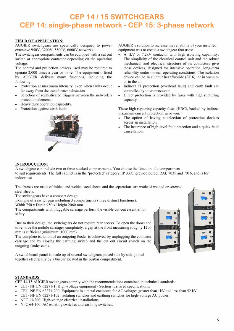
FIELD OF APPLICATION:
AUGIER switchgears are specifically designed to power
extensive 950V, 3200V, 5500V, 6600V networks.
The switchgear compartments can be equipped with a cut out
switch or appropriate contactor depending on the operating
voltage.
The control and protection devices used may be required to
operate 2,000 times a year or more. The equipment offered
by AUGIER delivers many functions, including the
following:
Protection at maximum intensity, even when faults occur
far away from the transformer substation
Selection of sophisticated triggers between the network’s
protection elements
Heavy duty operation capability.
Protection against earth faults
AUGIER’s solution to increase the reliability of your installed
equipment was to create a switchgear that uses:
A 1kV or 7.2kV contactor with high isolating capability.
The simplicity of the electrical control unit and the robust
mechanical and electrical structure of its contactors give
these devices, designed for intensive operation, long-term
reliability under normal operating conditions. The isolation
device can be in sulphur hexafluoride (SF 6), or in vacuum
or in the air
Indirect TI protection (overload fault) and earth fault are
controlled by microprocessor
Direct protection is provided by fuses with high rupturing
capacity.
These high rupturing capacity fuses (HRC), backed by indirect
maximum current protection, give you:
The option of having a selection of protection devices
across an installation
The insurance of high-level fault detection and a quick fault
cancellation.
INTRODUCTION:
A switchgear can include two or three stacked compartments. You choose the function of a compartment
to suit requirements. The full cabinet is in the ‘protected’ category, IP 3XC, grey-coloured, RAL 7035 and 7016, and is for
indoor use.
The frames are made of folded and welded steel sheets and the separations are made of welded or screwed
steel sheets.
The switchgears have a compact design.
Example of a switchgear including 3 compartments (three distinct functions):
Width 750 x Depth 950 x Height 2060 mm.
The compartments with pluggable carriage perform the visible cut-out essential for
safety.
Due to their design, the switchgears do not require rear access. To open the doors and
to remove the mobile carriages completely, a gap at the front measuring roughly 1200
mm is sufficient (minimum: 1000 mm).
The complete isolation of an outgoing feeder is achieved by unplugging the contactor
carriage and by closing the earthing switch and the cut out circuit switch on the
outgoing feeder cable.
A switchboard panel is made up of several switchgears placed side by side, joined
together electrically by a busbar located in the busbar compartment.
STANDARDS:
CEP 14/15 AUGIER switchgears comply with the recommendations contained in technical standards:
CEI - NF EN 62271-1: High-voltage equipment - Section 1: shared specifications.
CEI - NF EN 62271-200: Equipment in a metal enclosure for AC voltages greater than 1kV and less than 52 kV.
CEI - NF EN 62271-102: isolating switches and earthing switches for high-voltage AC power.
NFC 13-200: High-voltage electrical installations.
NFC 64-160: AC isolating switches and earthing switches.
6
Incoming
isolating switch
and Auxiliary transformer
Incoming
isolating switch
Coupling
isolating
switch
Auxiliary transformer
Isolating switch
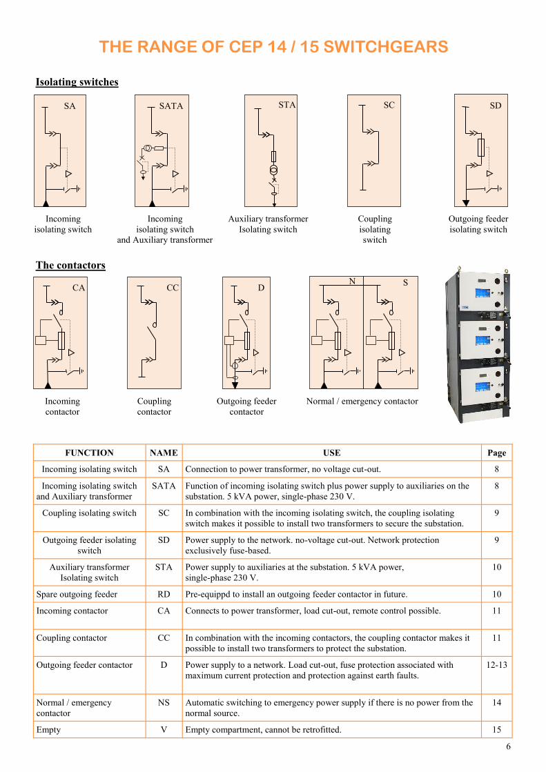
THE RANGE OF CEP 14 / 15 SWITCHGEARS
FUNCTION NAME USE Page
Incoming isolating switch SA Connection to power transformer, no voltage cut-out. 8
Incoming isolating switch
and Auxiliary transformer
SATA Function of incoming isolating switch plus power supply to auxiliaries on the
substation. 5 kVA power, single-phase 230 V.
8
Coupling isolating switch SC In combination with the incoming isolating switch, the coupling isolating
switch makes it possible to install two transformers to secure the substation.
9
Outgoing feeder isolating
switch
SD Power supply to the network. no-voltage cut-out. Network protection
exclusively fuse-based.
9
Auxiliary transformer
Isolating switch
STA Power supply to auxiliaries at the substation. 5 kVA power,
single-phase 230 V.
10
Spare outgoing feeder RD Pre-equippd to install an outgoing feeder contactor in future. 10
Incoming contactor CA Connects to power transformer, load cut-out, remote control possible. 11
Coupling contactor CC In combination with the incoming contactors, the coupling contactor makes it
possible to install two transformers to protect the substation.
11
Outgoing feeder contactor D Power supply to a network. Load cut-out, fuse protection associated with
maximum current protection and protection against earth faults.
12-13
Normal / emergency
contactor
NS Automatic switching to emergency power supply if there is no power from the
normal source.
14
Empty V Empty compartment, cannot be retrofitted. 15
SA SATA SC SD
Outgoing feeder
contactor
D
Outgoing feeder
isolating switch
Isolating switches
The contactors
CA
Incoming
contactor
CC
Coupling
contactor
STA
N S
Normal / emergency contactor
7
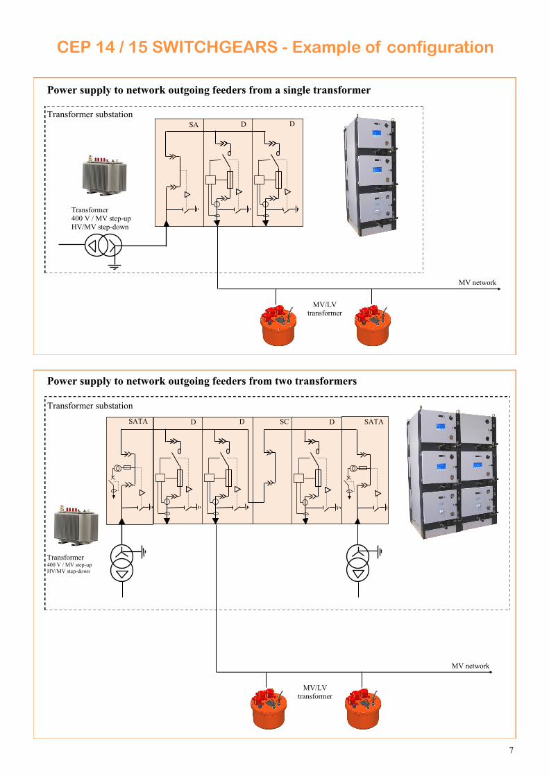
CEP 14 / 15 SWITCHGEARS - Example of configuration
Power supply to network outgoing feeders from a single transformer
SA D D
Transformer 400 V / MV step-up
HV/MV step-down
MV/LV transformer
MV network
Power supply to network outgoing feeders from two transformers
Transformer 400 V / MV step-up
HV/MV step-down
MV/LV transformer
MV network
D D SC D SATA SATA
Transformer substation
Transformer substation
8
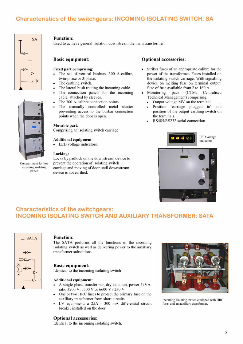
Characteristics of the switchgears: INCOMING ISOLATING SWITCH: SA
Function: Used to achieve general isolation downstream the main transformer.
Incoming isolating switch equipped with HRC
fuses and an auxiliary transformer.
Basic equipment:
Fixed part comprising: The set of vertical busbars, 300 A-calibre,
twin-phase or 3-phase.
The earthing switch.
The lateral bush routing the incoming cable.
The connection panels for the incoming
cable, attached by sleeves.
The 300 A-calibre connection points.
The manually controlled metal shutter
preventing access to the busbar connection
points when the door is open.
Movable part:
Comprising an isolating switch carriage
Additional equipment:
LED voltage indicators.
Locking: Locks by padlock on the downstream device to
prevent the operation of isolating switch
carriage and moving of door until downstream
device is not earthed.
Optional accessories:
Striker fuses of an appropriate calibre for the
power of the transformer. Fuses installed on
the isolating switch carriage. With signalling
device on melting fuse on terminal output.
Size of fuse available from 2 to 160 A.
Monitoring pack (CTM: Centralised
Technical Management) comprising:
Output voltage MV on the terminal.
Position ‘carriage plugged in’ and
position of the output earthing switch on
the terminals.
RS485/RS232 serial connection
Characteristics of the switchgears: INCOMING ISOLATING SWITCH AND AUXILIARY TRANSFORMER: SATA
SA
Function: The SATA performs all the functions of the incoming
isolating switch as well as delivering power to the auxiliary
transformer substations.
SATA
Compartment for low incoming isolating
switch
Basic equipment:
Identical to the incoming isolating switch
Additional equipment:
A single-phase transformer, dry isolation, power 5kVA,
ratio 3200 V, 5500 V or 6600 V / 230 V.
One or two HRC fuses to protect the primary fuse on the
auxiliary transformer from short circuits.
LV equipment: a 25A - 300 mA differential circuit
breaker installed on the door.
Optional accessories:
Identical to the incoming isolating switch.
LED voltage indicators
9
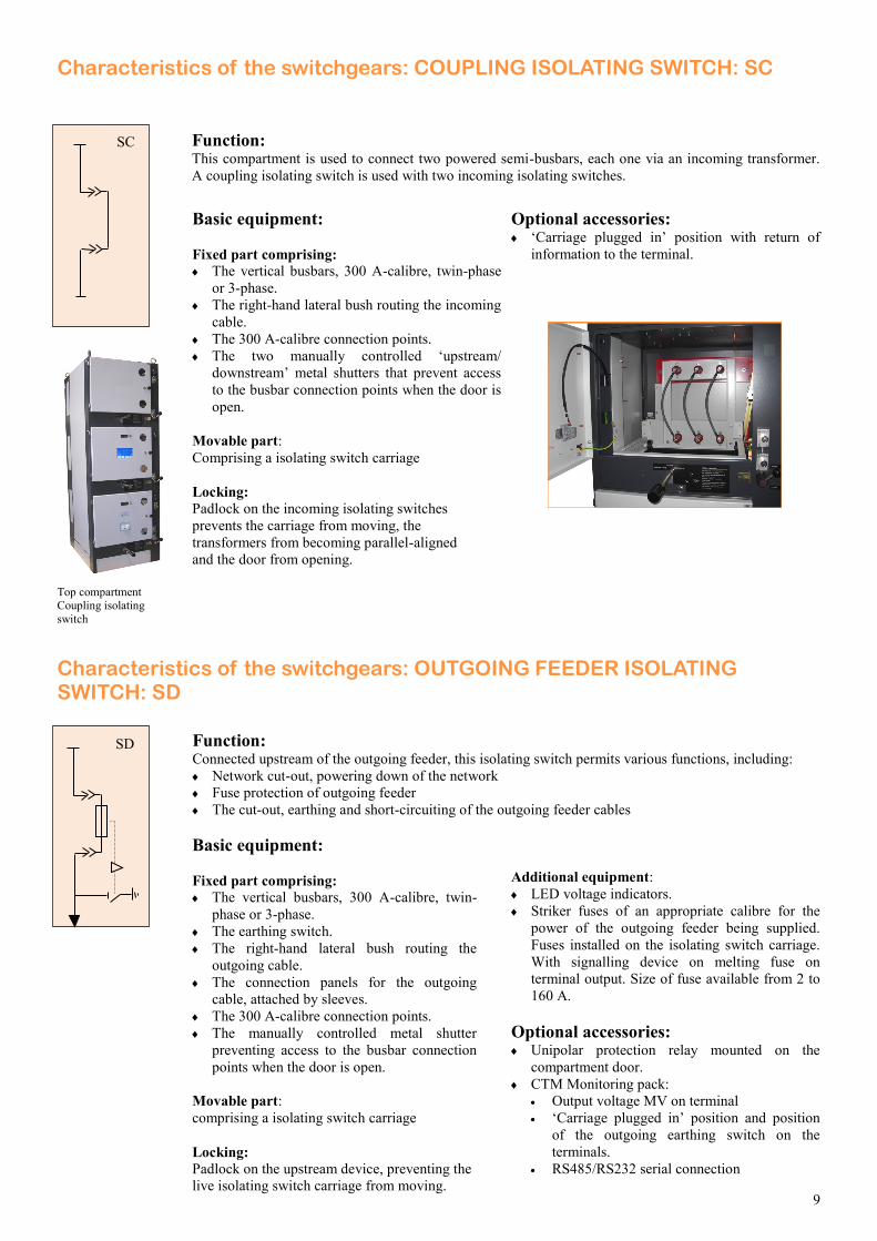
Basic equipment:
Fixed part comprising: The vertical busbars, 300 A-calibre, twin-phase
or 3-phase.
The right-hand lateral bush routing the incoming
cable.
The 300 A-calibre connection points.
The two manually controlled ‘upstream/
downstream’ metal shutters that prevent access
to the busbar connection points when the door is
open.
Movable part:
Comprising a isolating switch carriage
Locking: Padlock on the incoming isolating switches
prevents the carriage from moving, the
transformers from becoming parallel-aligned
and the door from opening.
Optional accessories:
‘Carriage plugged in’ position with return of
information to the terminal.
Characteristics of the switchgears: COUPLING ISOLATING SWITCH: SC
SC Function: This compartment is used to connect two powered semi-busbars, each one via an incoming transformer.
A coupling isolating switch is used with two incoming isolating switches.
Top compartment Coupling isolating
switch
Characteristics of the switchgears: OUTGOING FEEDER ISOLATING SWITCH: SD
SD Function: Connected upstream of the outgoing feeder, this isolating switch permits various functions, including:
Network cut-out, powering down of the network
Fuse protection of outgoing feeder
The cut-out, earthing and short-circuiting of the outgoing feeder cables
Basic equipment:
Fixed part comprising: The vertical busbars, 300 A-calibre, twin-
phase or 3-phase.
The earthing switch.
The right-hand lateral bush routing the
outgoing cable.
The connection panels for the outgoing
cable, attached by sleeves.
The 300 A-calibre connection points.
The manually controlled metal shutter
preventing access to the busbar connection
points when the door is open.
Movable part:
comprising a isolating switch carriage
Locking: Padlock on the upstream device, preventing the
live isolating switch carriage from moving.
Additional equipment:
LED voltage indicators.
Striker fuses of an appropriate calibre for the
power of the outgoing feeder being supplied.
Fuses installed on the isolating switch carriage.
With signalling device on melting fuse on
terminal output. Size of fuse available from 2 to
160 A.
Optional accessories:
Unipolar protection relay mounted on the
compartment door.
CTM Monitoring pack:
Output voltage MV on terminal
‘Carriage plugged in’ position and position
of the outgoing earthing switch on the
terminals.
RS485/RS232 serial connection
10
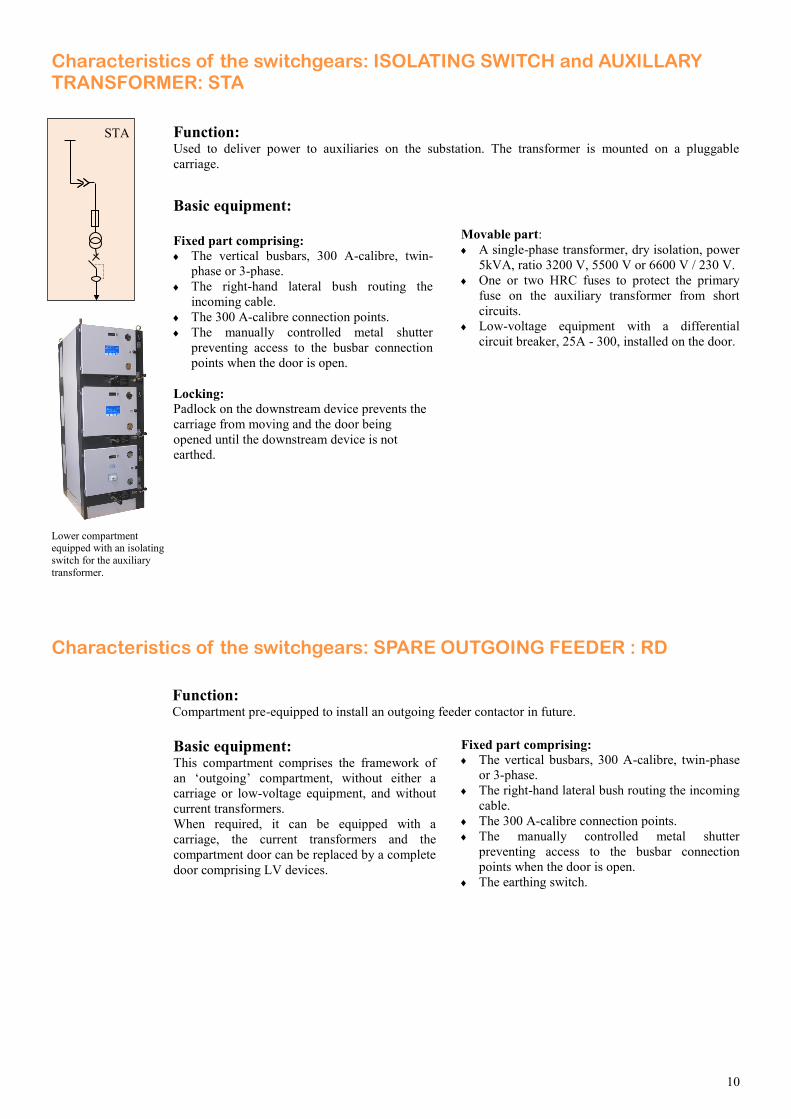
Basic equipment: This compartment comprises the framework of
an ‘outgoing’ compartment, without either a
carriage or low-voltage equipment, and without
current transformers.
When required, it can be equipped with a
carriage, the current transformers and the
compartment door can be replaced by a complete
door comprising LV devices.
Fixed part comprising: The vertical busbars, 300 A-calibre, twin-phase
or 3-phase.
The right-hand lateral bush routing the incoming
cable.
The 300 A-calibre connection points.
The manually controlled metal shutter
preventing access to the busbar connection
points when the door is open.
The earthing switch.
Characteristics of the switchgears: SPARE OUTGOING FEEDER : RD
Function: Compartment pre-equipped to install an outgoing feeder contactor in future.
Characteristics of the switchgears: ISOLATING SWITCH and AUXILLARY TRANSFORMER: STA
Function: Used to deliver power to auxiliaries on the substation. The transformer is mounted on a pluggable
carriage.
STA
Basic equipment:
Fixed part comprising: The vertical busbars, 300 A-calibre, twin-
phase or 3-phase.
The right-hand lateral bush routing the
incoming cable.
The 300 A-calibre connection points.
The manually controlled metal shutter
preventing access to the busbar connection
points when the door is open.
Locking: Padlock on the downstream device prevents the
carriage from moving and the door being
opened until the downstream device is not
earthed.
Movable part:
A single-phase transformer, dry isolation, power
5kVA, ratio 3200 V, 5500 V or 6600 V / 230 V.
One or two HRC fuses to protect the primary
fuse on the auxiliary transformer from short
circuits.
Low-voltage equipment with a differential
circuit breaker, 25A - 300, installed on the door.
Lower compartment equipped with an isolating
switch for the auxiliary
transformer.
11
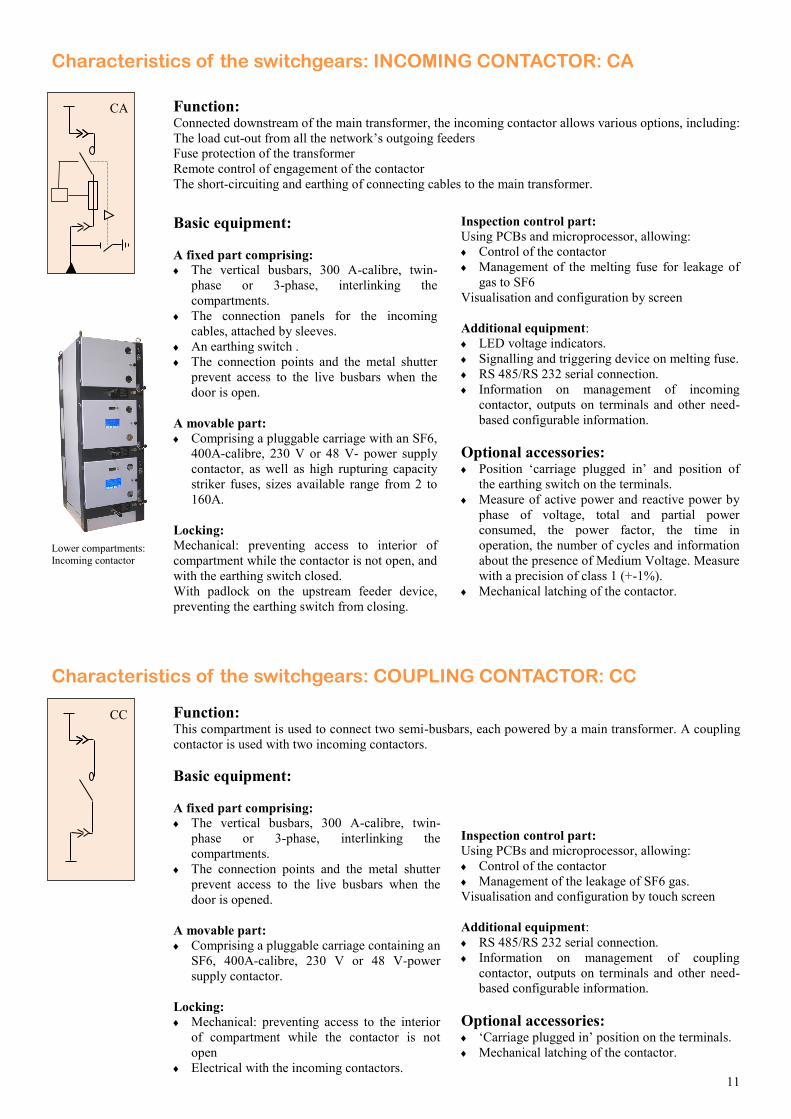
Function: Connected downstream of the main transformer, the incoming contactor allows various options, including:
The load cut-out from all the network’s outgoing feeders
Fuse protection of the transformer
Remote control of engagement of the contactor
The short-circuiting and earthing of connecting cables to the main transformer.
Basic equipment:
A fixed part comprising: The vertical busbars, 300 A-calibre, twin-
phase or 3-phase, interlinking the
compartments.
The connection panels for the incoming
cables, attached by sleeves.
An earthing switch .
The connection points and the metal shutter
prevent access to the live busbars when the
door is open.
A movable part: Comprising a pluggable carriage with an SF6,
400A-calibre, 230 V or 48 V- power supply
contactor, as well as high rupturing capacity
striker fuses, sizes available range from 2 to
160A.
Locking:
Mechanical: preventing access to interior of
compartment while the contactor is not open, and
with the earthing switch closed.
With padlock on the upstream feeder device,
preventing the earthing switch from closing.
Inspection control part:
Using PCBs and microprocessor, allowing:
Control of the contactor
Management of the melting fuse for leakage of
gas to SF6
Visualisation and configuration by screen
Additional equipment:
LED voltage indicators.
Signalling and triggering device on melting fuse.
RS 485/RS 232 serial connection.
Information on management of incoming
contactor, outputs on terminals and other need-
based configurable information.
Optional accessories:
Position ‘carriage plugged in’ and position of
the earthing switch on the terminals.
Measure of active power and reactive power by
phase of voltage, total and partial power
consumed, the power factor, the time in
operation, the number of cycles and information
about the presence of Medium Voltage. Measure
with a precision of class 1 (+-1%).
Mechanical latching of the contactor.
Characteristics of the switchgears: INCOMING CONTACTOR: CA
Lower compartments: Incoming contactor
CA
Characteristics of the switchgears: COUPLING CONTACTOR: CC
CC Function: This compartment is used to connect two semi-busbars, each powered by a main transformer. A coupling
contactor is used with two incoming contactors.
Basic equipment:
A fixed part comprising: The vertical busbars, 300 A-calibre, twin-
phase or 3-phase, interlinking the
compartments.
The connection points and the metal shutter
prevent access to the live busbars when the
door is opened.
A movable part: Comprising a pluggable carriage containing an
SF6, 400A-calibre, 230 V or 48 V-power
supply contactor.
Locking:
Mechanical: preventing access to the interior
of compartment while the contactor is not
open
Electrical with the incoming contactors.
Inspection control part:
Using PCBs and microprocessor, allowing:
Control of the contactor
Management of the leakage of SF6 gas.
Visualisation and configuration by touch screen
Additional equipment:
RS 485/RS 232 serial connection.
Information on management of coupling
contactor, outputs on terminals and other need-
based configurable information.
Optional accessories:
‘Carriage plugged in’ position on the terminals.
Mechanical latching of the contactor.
12
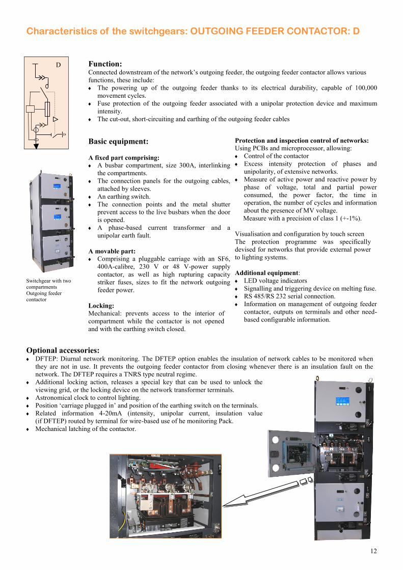
Function: Connected downstream of the network’s outgoing feeder, the outgoing feeder contactor allows various
functions, these include:
The powering up of the outgoing feeder thanks to its electrical durability, capable of 100,000
movement cycles.
Fuse protection of the outgoing feeder associated with a unipolar protection device and maximum
intensity.
The cut-out, short-circuiting and earthing of the outgoing feeder cables
Basic equipment:
A fixed part comprising: A busbar compartment, size 300A, interlinking
the compartments.
The connection panels for the outgoing cables,
attached by sleeves.
An earthing switch.
The connection points and the metal shutter
prevent access to the live busbars when the door
is opened.
A phase-based current transformer and a
unipolar earth fault.
A movable part: Comprising a pluggable carriage with an SF6,
400A-calibre, 230 V or 48 V-power supply
contactor, as well as high rupturing capacity
striker fuses, sizes to fit the network outgoing
feeder power.
Locking:
Mechanical: prevents access to the interior of
compartment while the contactor is not opened
and with the earthing switch closed.
Protection and inspection control of networks:
Using PCBs and microprocessor, allowing:
Control of the contactor
Excess intensity protection of phases and
unipolarity, of extensive networks.
Measure of active power and reactive power by
phase of voltage, total and partial power
consumed, the power factor, the time in
operation, the number of cycles and information
about the presence of MV voltage.
Measure with a precision of class 1 (+-1%).
Visualisation and configuration by touch screen
The protection programme was specifically
devised for networks that provide external power
to lighting systems.
Additional equipment:
LED voltage indicators
Signalling and triggering device on melting fuse.
RS 485/RS 232 serial connection.
Information on management of outgoing feeder
contactor, outputs on terminals and other need-
based configurable information.
Optional accessories:
DFTEP: Diurnal network monitoring. The DFTEP option enables the insulation of network cables to be monitored when
they are not in use. It prevents the outgoing feeder contactor from closing whenever there is an insulation fault on the
network. The DFTEP requires a TNRS type neutral regime.
Additional locking action, releases a special key that can be used to unlock the
viewing grid, or the locking device on the network transformer terminals.
Astronomical clock to control lighting.
Position ‘carriage plugged in’ and position of the earthing switch on the terminals.
Related information 4-20mA (intensity, unipolar current, insulation value
(if DFTEP) routed by terminal for wire-based use of he monitoring Pack.
Mechanical latching of the contactor.
Characteristics of the switchgears: OUTGOING FEEDER CONTACTOR: D
D
Switchgear with two compartments
Outgoing feeder
contactor
13
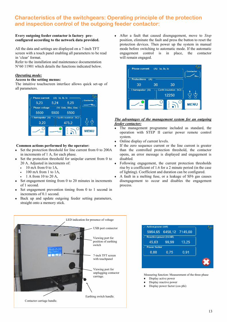
Every outgoing feeder contactor is factory pre-
configured according to the network data provided.
All the data and settings are displayed on a 7-inch TFT
screen with a touch panel enabling all parameters to be read
in ‘clear’ format.
Refer to the installation and maintenance documentation
N°60 11901 which details the functions indicated below.
Operating mode:
Access to the setting menus: The intuitive touchscreen interface allows quick set-up of
all parameters.
Common actions performed by the operator: Set the protection threshold for line current from 0 to 200A
in increments of 1 A, for each phase.
Set the protection threshold for unipolar current from 0 to
20 A. Adjusted in increments of:
10 mA from 0 to 1A,
100 mA from 1 to 1A,
1 A from 10 to 20 A,
Set engagement timing from 0 to 20 minutes in increments
of 1 second.
Set engagement prevention timing from 0 to 1 second in
increments of 0.1 second.
Back up and update outgoing feeder setting parameters,
straight onto a memory stick.
After a fault that caused disengagement, move to Stop
position, eliminate the fault and press the button to reset the
protection devices. Then power up the system in manual
mode before switching to automatic mode. If the automatic
engagement control is in place, the contactor
will remain engaged.
The advantages of the management system for an outgoing
feeder contactor: The management programme included as standard, the
operation with STEP II carrier power remote control
system.
Online display of current levels.
If the zero sequence current or the line current is greater
than the controlled protection threshold, the contactor
opens, an error message is displayed and engagement is
disabled.
Following engagement, the current protection thresholds
rise by a coefficient of 1.6 for a 2 minute period (in the case
of lighting). Coefficient and duration can be configured.
A fault in a melting fuse, or a leakage of SF6 gas causes
disengagement to occur and disables the engagement
process.
Characteristics of the switchgears: Operating principle of the protection and inspection control of the outgoing feeder contactor:
Measuring function: Measurement of the three phase
Display active power
Display reactive power
Display power factor (cos phi)
Contactor carriage handle.
Earthing switch handle.
7-inch TFT screen with touchpanel
LED indication for presence of voltage
USB port connector
Viewing port for unplugging contactor
carriage.
Viewing port for position of earthing
switch
14
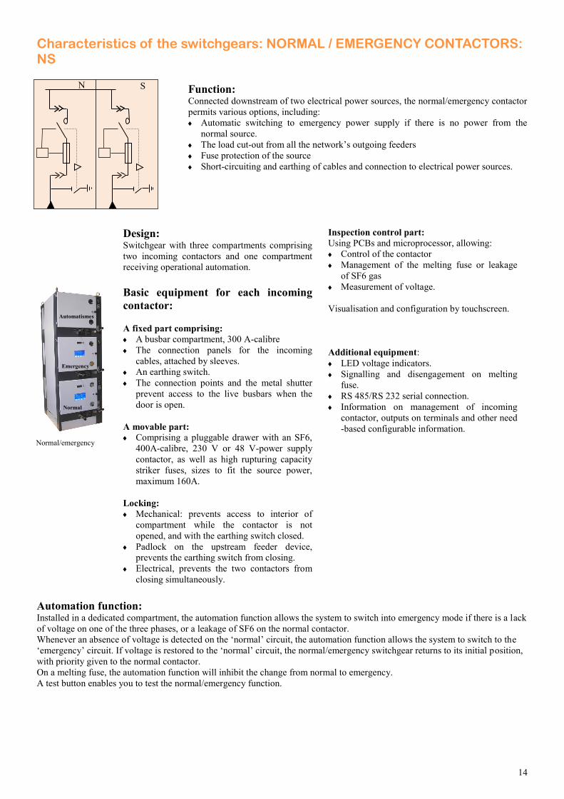
Characteristics of the switchgears: NORMAL / EMERGENCY CONTACTORS: NS
Function: Connected downstream of two electrical power sources, the normal/emergency contactor
permits various options, including:
Automatic switching to emergency power supply if there is no power from the
normal source.
The load cut-out from all the network’s outgoing feeders
Fuse protection of the source
Short-circuiting and earthing of cables and connection to electrical power sources.
Design: Switchgear with three compartments comprising
two incoming contactors and one compartment
receiving operational automation.
Basic equipment for each incoming
contactor:
A fixed part comprising: A busbar compartment, 300 A-calibre
The connection panels for the incoming
cables, attached by sleeves.
An earthing switch.
The connection points and the metal shutter
prevent access to the live busbars when the
door is open.
A movable part: Comprising a pluggable drawer with an SF6,
400A-calibre, 230 V or 48 V-power supply
contactor, as well as high rupturing capacity
striker fuses, sizes to fit the source power,
maximum 160A.
Locking:
Mechanical: prevents access to interior of
compartment while the contactor is not
opened, and with the earthing switch closed.
Padlock on the upstream feeder device,
prevents the earthing switch from closing.
Electrical, prevents the two contactors from
closing simultaneously.
Inspection control part:
Using PCBs and microprocessor, allowing:
Control of the contactor
Management of the melting fuse or leakage
of SF6 gas
Measurement of voltage.
Visualisation and configuration by touchscreen.
Additional equipment:
LED voltage indicators.
Signalling and disengagement on melting
fuse.
RS 485/RS 232 serial connection.
Information on management of incoming
contactor, outputs on terminals and other need
-based configurable information.
Automation function:
Installed in a dedicated compartment, the automation function allows the system to switch into emergency mode if there is a lack
of voltage on one of the three phases, or a leakage of SF6 on the normal contactor.
Whenever an absence of voltage is detected on the ‘normal’ circuit, the automation function allows the system to switch to the
‘emergency’ circuit. If voltage is restored to the ‘normal’ circuit, the normal/emergency switchgear returns to its initial position,
with priority given to the normal contactor.
On a melting fuse, the automation function will inhibit the change from normal to emergency.
A test button enables you to test the normal/emergency function.
Normal/emergency
Normal
Emergency
Automatismes
N S
15
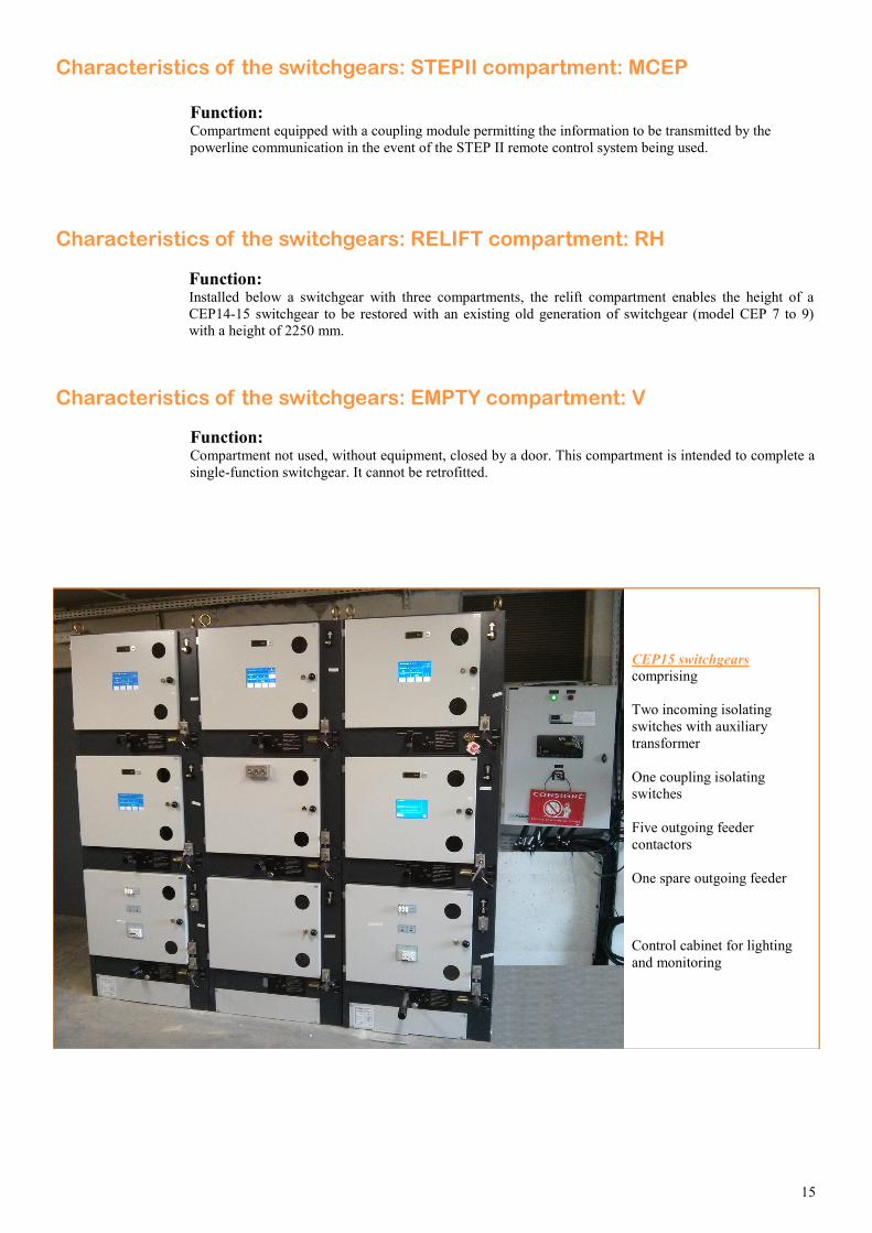
Characteristics of the switchgears: STEPII compartment: MCEP
Characteristics of the switchgears: EMPTY compartment: V
Function: Compartment not used, without equipment, closed by a door. This compartment is intended to complete a
single-function switchgear. It cannot be retrofitted.
Characteristics of the switchgears: RELIFT compartment: RH
Function: Installed below a switchgear with three compartments, the relift compartment enables the height of a
CEP14-15 switchgear to be restored with an existing old generation of switchgear (model CEP 7 to 9)
with a height of 2250 mm.
Function: Compartment equipped with a coupling module permitting the information to be transmitted by the
powerline communication in the event of the STEP II remote control system being used.
CEP15 switchgears comprising
Two incoming isolating
switches with auxiliary
transformer
One coupling isolating
switches
Five outgoing feeder
contactors
One spare outgoing feeder
Control cabinet for lighting
and monitoring
16
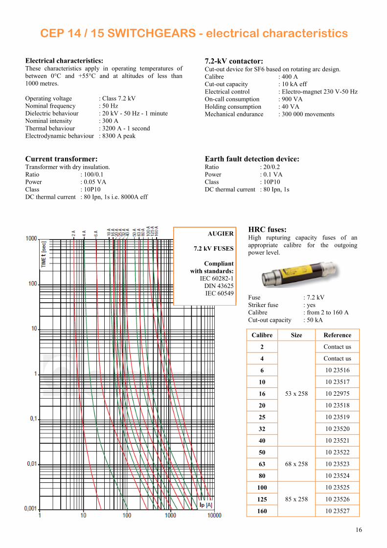
Electrical characteristics: These characteristics apply in operating temperatures of
between 0°C and +55°C and at altitudes of less than
1000 metres.
Operating voltage : Class 7.2 kV
Nominal frequency : 50 Hz
Dielectric behaviour : 20 kV - 50 Hz - 1 minute
Nominal intensity : 300 A
Thermal behaviour : 3200 A - 1 second
Electrodynamic behaviour : 8300 A peak
CEP 14 / 15 SWITCHGEARS - electrical characteristics
7.2-kV contactor: Cut-out device for SF6 based on rotating arc design.
Calibre : 400 A
Cut-out capacity : 10 kA eff
Electrical control : Electro-magnet 230 V-50 Hz
On-call consumption : 900 VA
Holding consumption : 40 VA
Mechanical endurance : 300 000 movements
Current transformer: Transformer with dry insulation.
Ratio : 100/0.1
Power : 0.05 VA
Class : 10P10
DC thermal current : 80 Ipn, 1s i.e. 8000A eff
AUGIER
7.2 kV FUSES
Compliant
with standards:
IEC 60282-1
DIN 43625
IEC 60549
HRC fuses: High rupturing capacity fuses of an
appropriate calibre for the outgoing
power level.
Fuse : 7.2 kV
Striker fuse : yes
Calibre : from 2 to 160 A Cut-out capacity : 50 kA
Earth fault detection device:
Ratio : 20/0.2
Power : 0.1 VA
Class : 10P10
DC thermal current : 80 Ipn, 1s
Calibre Size Reference
2
53 x 258
Contact us
4 Contact us
6 10 23516
10 10 23517
16 10 22975
20 10 23518
25 10 23519
32 10 23520
40 10 23521
50
68 x 258
10 23522
63 10 23523
80 10 23524
100 10 23525
85 x 258 125 10 23526
160 10 23527
17
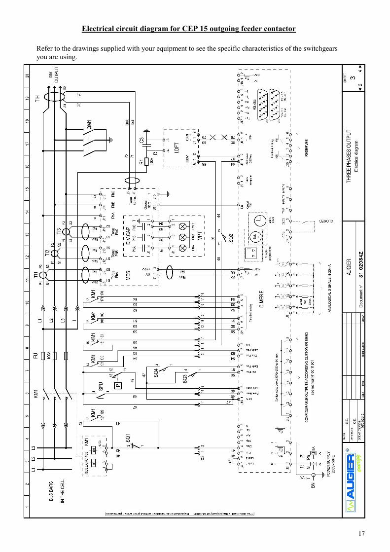
Electrical circuit diagram for CEP 15 outgoing feeder contactor
Refer to the drawings supplied with your equipment to see the specific characteristics of the switchgears
you are using.
18
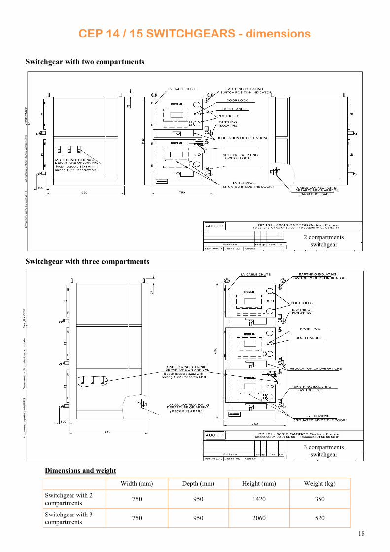
CEP 14 / 15 SWITCHGEARS - dimensions
Switchgear with two compartments
Switchgear with three compartments
Dimensions and weight
Width (mm) Depth (mm) Height (mm) Weight (kg)
Switchgear with 2
compartments 750 950 1420 350
Switchgear with 3
compartments 750 950 2060 520
2 compartments
switchgear
3 compartments
switchgear
19
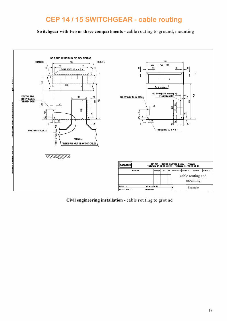
CEP 14 / 15 SWITCHGEAR - cable routing
Switchgear with two or three compartments - cable routing to ground, mounting
Civil engineering installation - cable routing to ground
cable routing and
mounting
Example
20
The locking devices are mechanical, operational and appropriate to the configuration of the panel. These prevent, most
importantly:
The carriage being unplugged or plugged with the contactor closed.
The earthing switch being closed with the carriage contactor plugged in.
The access door to the equipment being opened when the earthing switch is open.
The earthing switch handle can be locked. This prevents the carriage from being plugged back in when the earthing switch is
closed. Moreover, a ‘Ronis’ type of lock enables the compartment to be locked in ‘closed’ position, preventing access to the
interior of the compartment.
Optional: An additional ‘Ronis’ lock can be associated with a watch locking key, per mitting access to the network
transformers if the earthing switch is closed.
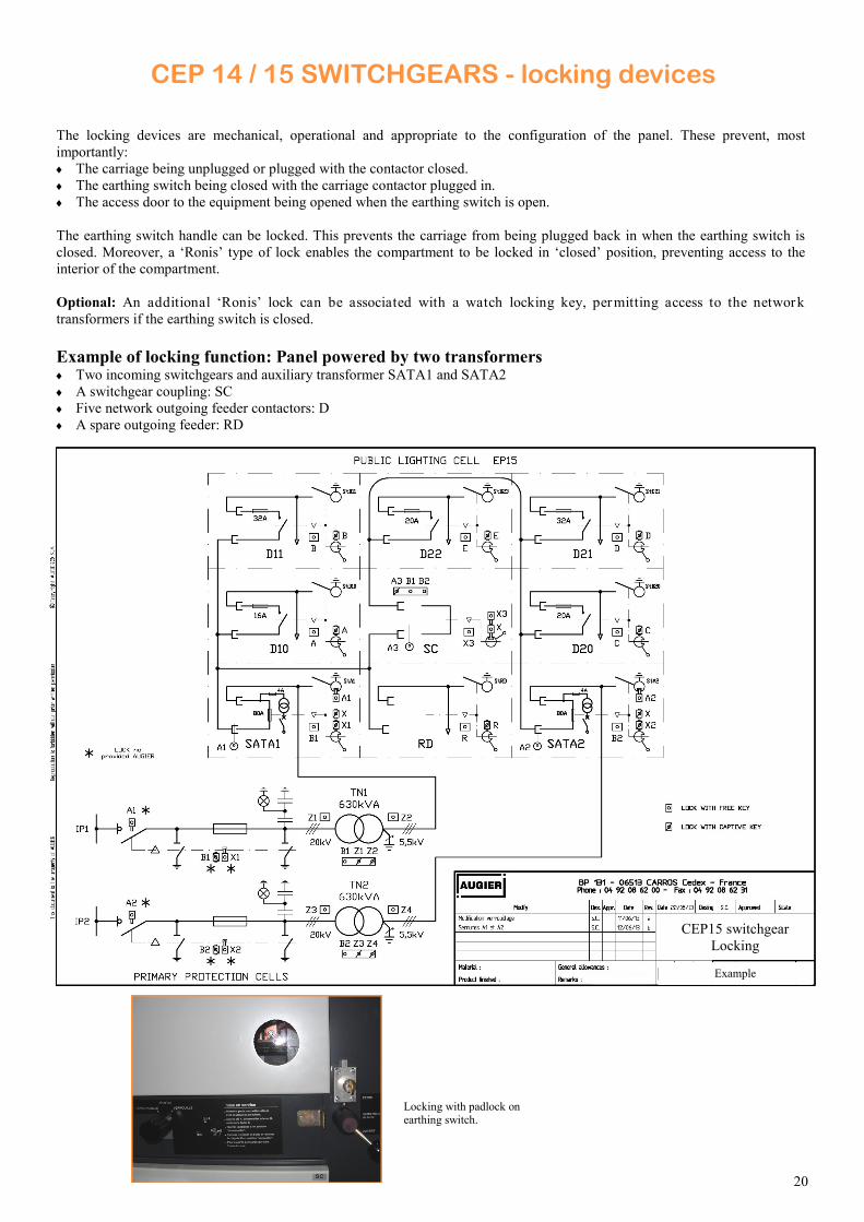
CEP 14 / 15 SWITCHGEARS - locking devices
CELLULES CEP 14 / 15 - Sécurité
Volet …...
Example of locking function: Panel powered by two transformers Two incoming switchgears and auxiliary transformer SATA1 and SATA2
A switchgear coupling: SC
Five network outgoing feeder contactors: D
A spare outgoing feeder: RD
Locking with padlock on earthing switch.
CEP15 switchgear
Locking
Example
21
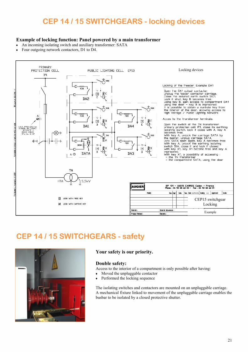
CEP 14 / 15 SWITCHGEARS - locking devices
Example of locking function: Panel powered by a main transformer An incoming isolating switch and auxiliary transformer: SATA
Four outgoing network contactors, D1 to D4.
CEP 14 / 15 SWITCHGEARS - safety
Your safety is our priority.
Double safety:
Access to the interior of a compartment is only possible after having:
Moved the unpluggable contactor
Performed the locking sequence
The isolating switches and contactors are mounted on an unpluggable carriage.
A mechanical fixture linked to movement of the unpluggable carriage enables the
busbar to be isolated by a closed protective shutter.
CEP15 switchgear
Locking
Example
Locking devices
22
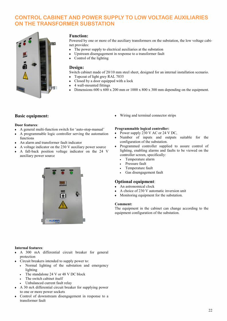
CONTROL CABINET AND POWER SUPPLY TO LOW VOLTAGE AUXILIARIES ON THE TRANSFORMER SUBSTATION
Function: Powered by one or more of the auxiliary transformers on the substation, the low voltage cabi-
net provides:
The power supply to electrical auxiliaries at the substation
Upstream disengagement in response to a transformer fault
Control of the lighting
Design: Switch cabinet made of 20/10 mm steel sheet, designed for an internal installation scenario.
Topcoat of light grey RAL 7035
Closed by a door equipped with a lock
4 wall-mounted fittings
Dimensions 600 x 600 x 200 mm or 1000 x 800 x 300 mm depending on the equipment.
Basic equipment:
Door features:
A general multi-function switch for ‘auto-stop-manual’
A programmable logic controller serving the automation
functions
An alarm and transformer fault indicator
A voltage indicator on the 230 V auxiliary power source
A fall-back position voltage indicator on the 24 V
auxiliary power source
Internal features:
A 300 mA differential circuit breaker for general
protection
Circuit breakers intended to supply power to:
Normal lighting of the substation and emergency
lighting
The standalone 24 V or 48 V DC block
The switch cabinet itself
Unbalanced current fault relay
A 30 mA differential circuit breaker for supplying power
to one or more power sockets
Control of downstream disengagement in response to a
transformer fault
Wiring and terminal connector strips
Programmable logical controller:
Power supply 230 V AC or 24 V DC,
Number of inputs and outputs suitable for the
configuration of the substation.
Programmed controller supplied to assure control of
lighting, enabling alarms and faults to be viewed on the
controller screen, specifically:
Temperature alarm
Pressure fault
Temperature fault
Gas disengagement fault
Optional equipment: An astronomical clock
A choice of 230 V automatic inversion unit
Monitoring equipment for the substation.
Comment:
The equipment in the cabinet can change according to the
equipment configuration of the substation.

23
CEP 14 / 15 SWITCHGEARS: related services
Advice and documentation:
On-site commissioning support for
switchgears:
Servicing and maintenance:
Training:
Specialists are here to listen to you and to propose the best possible options from
the list of equipment.
The switchgears are delivered in factory-configured condition according to the
replaced technical elements.
Each switchgear is supplied with:
Notification of commissioning of the ‘mechanical section’, enabling the
switchgear to be installed
Notification of commissioning of the ‘control parts’ explaining the
configuration and use of the graphic user interface.
Connection diagram
Locking diagram
Electrical circuit diagram
Augier technical staff are there to support you when you start up the equipment
line-up. This commissioning process also involves:
Checking the locking functions
Checking the wiring options
Checking protection devices and testing their function.
We recommend arranging for servicing and maintenance of the switchgears once a
year.
An Augier technician can do this for you.
Length of time involved in this work: One day per series of three compartments.
Augier is a certified training organisation. Certification N° 93060176606
Training provided on-site, on the hardware and equipment used on a daily basis.
24
AUGIER IS CERTIFIED ISO 9001 SINCE 1995
60 1
1952
Wit
h c
onst
ant
imp
rovem
en
ts,
the
man
ufa
ctu
rer
may a
lter
info
rmat
ion w
itho
ut
pri
or
war
nin
g


