Download - SUPPLEMENTAL GEOTECHNICAL EVALUATION
2195 Faraday Avenue ♦ Suite K ♦ Carlsbad, California 92008-7207 ♦ Ph: 760-431-3747 ♦ Fax: 760-431-3748 ♦ www.eeitiger.com
SUPPLEMENTAL
GEOTECHNICAL EVALUATION
Proposed Residential Development
514 Morse Street
Oceanside, California
October 18, 2013
EEI Project No.: SHO-71361.4a


TABLE OF CONTENTS
1.0 INTRODUCTION ................................................................................................................................. 1 1.1 Purpose ....................................................................................................................................... 1
1.2 Intent ........................................................................................................................................... 1
1.3 Project Description ..................................................................................................................... 1
1.4 Scope of Services ....................................................................................................................... 2
2.0 BACKGROUND .................................................................................................................................... 2 2.1 Site Description .......................................................................................................................... 2
2.2 Site Topography….... ................................................................................................................. 3
2.3 Geologic Setting ......................................................................................................................... 3
2.4 Regional Groundwater ............................................................................................................... 3
3.0 FAULTING AND SEISMICITY ......................................................................................................... 4
Table 1 – Summary of Major Active Faults ..................................................................................... 4
3.1 Seismic Parameters and Peak Ground Acceleration ................................................................... 4
3.2 Ground Lurching or Shallow Ground Rupture ........................................................................... 5
3.3 Liquefaction................................................................................................................................ 5
3.4 Seismic Induced Settlement ....................................................................................................... 5
4.0 FIELD EXPLORATION AND LABORATORY TESTING ............................................................ 6
4.1 Field Exploration ........................................................................................................................ 6
4.2 Subsurface Conditions ................................................................................................................ 6
4.3 Laboratory Testing and Classification ........................................................................................ 7
4.3.1 Grain Size Distribution ............................................................................................... 7
4.3.2 Liquid Limits, Plastic Limits, and Plasticity Index .................................................... 7
4.3.3 Moisture Content and Dry Density ........................................................................... 7
4.3.4 Maximum Dry Density and Optimum Moisture Content ........................................... 7
4.3.5 Direct Shear ................................................................................................................ 8
4.3.6 Expansion Index ......................................................................................................... 8
4.3.7 Sulfate-Corrosion ....................................................................................................... 8
5.0 SLOPE STABILITY ANALYSIS ........................................................................................................ 8
5.1 General ....................................................................................................................................... 8
5.2 Slope Stability ............................................................................................................................ 8
5.2.1 Selection of Soil Parameters ....................................................................................... 8
Table 2 – Soil Parameters for Slope Stability Analysis....................................................... 9
5.2.2 Stability of Existing Slopes ........................................................................................ 9
5.2.3 Stability of Cut Slopes .............................................................................................. 10
5.2.4 Stability of Fill Slope Stability ................................................................................. 10
5.2.5 Surficial Slope Stability ............................................................................................ 10
5.2.6 Seismic Slope Stability ............................................................................................. 10
5.3 Conclusions .............................................................................................................................. 10
6.0 RECOMMENDATIONS .................................................................................................................... 12
6.1 General ..................................................................................................................................... 12
6.2 Site Preparation and Grading ................................................................................................... 12
6.3 Remedial Earthwork ................................................................................................................. 13
6.4 Cut-Fill Transition and Cut Lots .............................................................................................. 13
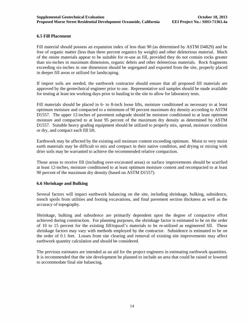
6.5 Fill Placement ........................................................................................................................... 14
6.6 Shrinkage and Bulking ............................................................................................................. 14
6.7 Graded Slopes

7.0 PRELIMINARY FOUNDATION RECOMMENDATIONS .......................................................... 15
7.1 General ..................................................................................................................................... 15
7.2 Foundation Design ................................................................................................................... 16
7.3 Footing Setbacks ...................................................................................................................... 16
7.4 Construction ............................................................................................................................. 16
7.5 Concrete Slab-on-Grade ........................................................................................................... 17
7.6 Retaining Walls ........................................................................................................................ 18
7.7 Construction Observation and Testing ..................................................................................... 19
8.0 PRELIMINARY PAVEMENT DESIGN RECOMMENDATIONS ............................................. 19
Table 3 –Preliminary Pavement Design Recommendations .......................................................... 20
9.0 DEVELOPMENT RECOMMENDATIONS ................................................................................... 20
9.1 Landscape Maintenance and Planting ...................................................................................... 20
9.2 Site Drainage ............................................................................................................................ 20
9.3 Stormwater Disposal Systems .................................................................................................. 20
9.3.1 Percolation Testing ................................................................................................... 21
Table 4 – Percolation Test Results .................................................................................... 21
9.3.2 Summary of Findings ............................................................................................... 21
9.3.3 Structural Setback from Retention Devices ............................................................. 21
9.4 Additional Site Improvements .................................................................................................. 22
9.5Trenching................................................................................................................................... 22
9.6 Utility Backfill .......................................................................................................................... 22
10.0 PLAN REVIEW ............................................................................................................................... 22
11.0 LIMITATIONS ................................................................................................................................ 23
12.0 REFERENCES ................................................................................................................................. 24
FIGURES
Figure 1 – Site Vicinity Map
Figure 2 – Aerial Site Map
Figure 3– Boring Location and Geologic Map
Figure 4– Cross Section A-A’
Figure 5– Cross Section B-B’
Figure 6 – Cross Section C-C’
Figure 7– Cross Section D-D’
Figure 8– Cross Section E-E’
APPENDICES
Appendix A – Soil Classification Chart and Boring Logs
Appendix B – Laboratory Test Data
Appendix C – Slope Stability Analysis
Appendix D – Earthwork and Grading Guidelines
Distribution: (2) Addressee
(1) Addressee (electronic copy)

Supplemental Geotechnical Evaluation October 18, 2013
Proposed Morse Street Residential Development Oceanside, California EEI Project No.: SHO-71361.4a
1
1.0 INTRODUCTION
1.1 Purpose
The purpose of this supplemental evaluation was to provide geotechnical information to Shopoff Group
Advisors, LP (herewith referred to as “Client”), regarding the proposed residential development in
Oceanside, San Diego County, California. The information developed in this evaluation is intended to
provide Shopoff and other members of the design team with an understanding of the physical conditions
of site-specific subsurface soils, groundwater, and the regional geologic setting which could affect the
cost or design of the proposed development during the design stages of the project (Site Vicinity Map-
Figure 1, Aerial Site-Figure 2, and Boring Location Map-Figure 3).
This geotechnical evaluation has been conducted in general accordance with the accepted geotechnical
engineering principles and in general conformance with the approved proposal and cost estimate for the
project by EEI, dated August 30, 2011.
EEI conducted onsite field exploration on October 19, 2011 and November 14, 2012 that included drilling
and sampling of nine hollow stem auger geotechnical borings for the proposed Morse Townhomes
residential development. A geotechnical field reconnaissance was performed on October 15, 2013. This
geotechnical evaluation has been prepared for the sole use of Shopoff Group Advisors, LP. Other parties,
without the express written consent of EEI and Shopoff Advisors, LP, should not rely upon this
geotechnical study.
1.2 Intent
It is the intent of this report to aid in the design and completion of the proposed development.
Implementation of the advice presented in subsequent sections of this report is intended to reduce risk
associated with construction projects. The professional opinions and geotechnical advice contained in
this report are not intended to imply total performance of the project or guarantee that unusual or variable
conditions will not be discovered during or after construction.
The scope of our evaluation is limited to the area explored that is shown on the Geotechnical Maps
(Figures 3). This evaluation does not and should in no way be construed to encompass any areas beyond
the specific area of the proposed construction as indicated to us by the client. Further, no evaluation of
any existing site improvements is included. The scope is based on our understanding of the project and
the client’s needs, and geotechnical engineering standards normally used on similar projects in this
region.
1.3 Project Description
We understand that the proposed development is for the construction of multi-family residential buildings
for 38 units, along with related improvements including underground utilities, retaining walls, paved
parking and drive areas, and other associated improvements. The residences are anticipated to be
constructed of wood frame and slab-on-grade construction. No foundation plans were available at the
time of our preparation of this report; however, foundation loads are anticipated to be typical for the
planned residential construction. Based on a development plan by O’Day Consultants (2012), grading at
the site is anticipated to generally consist of cuts and fills of less than 5 feet.

Supplemental Geotechnical Evaluation October 18, 2013
Proposed Morse Street Residential Development Oceanside, California EEI Project No.: SHO-71361.4a
2
1.4 Scope of Services
The scope of our services included:
• A review of readily available data pertinent to the subject property, including published and
unpublished geologic maps, and soils data for the area (References).
• The drilling and logging of nine hollow stem auger (HSA) borings to depths on the order of 5 to
36 feet below the existing ground surface across the site. The approximate locations of each of
our borings are presented on Figure 3 (Boring Location Map).
• An evaluation of seismicity and geologic hazards that includes an evaluation of faulting and
liquefaction potential.
• Completion of laboratory testing of representative earth materials encountered onsite to ascertain
their pertinent soils engineering properties, including corrosion potential (Appendix B).
• Slope stability analysis of deep-seated and surficial stability of the subject existing slopes and
proposed slopes.
• The preparation of this report which presents our findings, conclusions, and recommendations
regarding the proposed development.
2.0 BACKGROUND
2.1 Site Description
The site encompasses approximately 2.4-acres and is situated within the southwestern portion of
Oceanside, California. More specifically, the site is located along the east side of the Pacific Coast
Highway (PCH) at the northeast corner of PCH and Morse Street in Oceanside, California. The subject
property is presently vacant. Formerly, the site was occupied by a 56-unit mobile home residential
development, with an address of 514 Morse Street. Paved drive areas and concrete slabs remain on the
site along with power poles and utility risers. The ground surface at the site is moderately to gently
sloping generally toward the south. Slopes bound the north and west sides of the subject property and
descend relatively steeply. The subject property is generally bordered by commercial properties to the
east, south, and west, and residential property to the north. A site vicinity map is attached as Figure 1.
Current access to the site is afforded through a gate along Morse Street, which bounds the property to the
south. Scattered trees, some bushes and relatively sparse vegetation are present. The descending slopes
are covered by relatively sparse to dense ground cover.
The center of the property is situated at 33.1791° north latitude and 117.3648° west longitude (Google
Earth®, 2011). The Assessor Parcel Number (APN) currently assigned to the property is 153-041-01

Supplemental Geotechnical Evaluation October 18, 2013
Proposed Morse Street Residential Development Oceanside, California EEI Project No.: SHO-71361.4a
3
2.2 Site Topography
The subject property is situated within the United States Geological Survey (USGS) San Luis Rey,
California 7.5 Minute Quadrangle map (USGS, 1997). A review of this topographic map indicates that
the ground surface of the subject property is approximately 40 feet above mean sea level (amsl). The
subject site ground surface is overall gently to moderately sloping toward the west and south. Relatively
steep north and west facing descending slopes that are up to approximately 25 feet in height bound the
north and west sides of the site. Surface water appears to drain in a southerly direction towards Morse
Street. An aerial site map is attached as Figure 2.
2.3 Geologic Setting
Regionally, the area is situated within the Peninsular Ranges Geomorphic Province and the Transverse
Ranges Geomorphic Province of California (CGS, 2002b). The Peninsular Ranges are essentially a series
of ranges separated by northwest trending valleys, sub-parallel to faults branching from the San Andreas
Fault system. The northern portion of this Province is bounded by the Transverse Ranges Geomorphic
Province. The Peninsular Ranges extend into Lower California (and Baja), and are bound on the east by
the Colorado Desert. The predominant structural feature that has affected the geologic evolution of the
province is the San Andreas Fault.
Regional geologic maps of the site vicinity (CGS online geologic interactive maps) indicate the property
is underlain by Quaternary-aged and Tertiary-aged marine sedimentary deposits. Locally, the property
and vicinity is mapped as being underlain by Quaternary-aged Terrace Deposits and Eocene-aged
sedimentary deposits of the Santiago Formation (CDMG, 1996). Regionally, bedding layers within the
Santiago Formation in the vicinity of the site are mapped as trending east-west and generally dip gently to
the north up to 5 degrees. In the vicinity of the project site, the deposits are locally mantled by artificial
fill materials and topsoil of varying thicknesses.
Due to the proximity of the site area to several nearby active faults, strong ground shaking could occur at
the site as a result of an earthquake on any one of the faults. Our review indicates that there are no known
active faults crossing the site (Jennings, 1994, 2010) and the site is not within a State of California
Earthquake Fault Zone (Hart and Bryant, 1997, CDMG, 2000).
2.4 Regional Groundwater
Subsurface water was not encountered in any of our exploratory boring excavations performed during our
study to the maximum depths explored of 36 feet. Regional groundwater depths are anticipated to be
greater than 40 feet below the existing site grades. However, it should be noted that variations in
subsurface water (including perched water zones and seepage) may result from fluctuations in the ground
surface topography, subsurface stratification, precipitation, irrigation and other factors that may not have
been evident at the time of our subsurface exploration.
In general, groundwater is expected to follow the direction of surface topography. Based on topography,
regional groundwater flow direction can be expected to generally be in a westerly to southwesterly
direction (USGS, 1997).

Supplemental Geotechnical Evaluation October 18, 2013
Proposed Morse Street Residential Development Oceanside, California EEI Project No.: SHO-71361.4a
4
3.0 FAULTING AND SEISMICITY
The portion of Southern California that includes the subject site is considered to be seismically active.
Due to the proximity of the site area to several nearby active faults, strong ground shaking could occur at
the site as a result of an earthquake on any one of the faults. Our review indicates that there are no known
active faults crossing the site (Jennings, 1994, 2010) and the site is not within a State of California
Earthquake Fault Zone (Hart and Bryant, 1997). It is our opinion, therefore, that the likelihood of surface
fault rupture at the site is low. The following table provides a summary of active fault zones within an
approximately 50-mile radius of the subject property that may have a considerable effect on the subject
property in the event significant activity is experienced. Fault names and approximate distances are based
upon information provided in applicable references (Blake, 2000; Jennings, 1994).
TABLE 1
Summary of Major Active Faults
Fault Name Approximate Distance From Site
miles (kilometers)
Maximum Moment
Magnitude
Newport Inglewood (offshore) 4.0 (6.5) 7.1
Rose Canyon 5.2 (8.3) 7.2
Coronado Bank 21.0 (33.8) 7.6
Elsinore (Temecula) 23.9 (38.5) 6.8
Elsinore (Julian) 24.5 (39.4) 7.1
Elsinore (Glen Ivy) 32.1 (51.6) 6.8
San Joaquin Hills 32.9 (53.0) 6.6
Palos Verdes 34.0 (54.7) 7.3
Newport-Inglewood (L.A. Basin) 43.8 (70.5) 7.1
Chino-Central Ave. (Elsinore) 44.9 (72.3) 6.7
Earthquake Valley 45.3 (72.9) 6.5
San Jacinto-Anza 46.4 (74.6) 7.2
San Jacinto-San Jacinto Valley 46.6 (75.0) 6.9
Whittier 49.2 (79.2) 6.8
3.1 Seismic Parameters
Maximum considered ground motion maps provided in the California Building Code (CBC, 2010) were
utilized with coordinates of 33.1791° north latitude and 117.3648° west longitude, to determine the site
seismic parameters. EEI utilized seismic design criteria provided in the CBC (2010).

Supplemental Geotechnical Evaluation October 18, 2013
Proposed Morse Street Residential Development Oceanside, California EEI Project No.: SHO-71361.4a
5
In accordance with the guidelines of the CBC (2010), the spectral parameters for the site (based on a Site
Class B soil) are estimated to be Ss = 1.343g and S1 = 0.508g. Based on the geotechnical data obtained
during our subsurface exploration, it is our opinion that the site can be classified as Class C per the 2010
CBC (Table 1613.5.2). Consequently, Site Coefficients Fa= 1.0 and Fv = 1.3 appear to be appropriate for
the site. Based on this information, the adjusted maximum considered earthquake spectral response
parameters SMS = 1.343g and SM1 = 0.660g are recommended for seismic design of the project. Assuming
an occupancy category of II (Table 1604.5), an SDs value of 0.895g and an SD1 value of 0.440g,the
proposed residential buildings at the site can be assigned a seismic design category of D [Table 1613.5.6
(1) and (2)]. Final selection of the appropriate seismic design coefficients should be made by the
structural consultant based on the local laws and ordinances, expected building response and desired level
of conservatism.
Structures should be designed in accordance with seismic design criteria developed by the Structural
Engineers Association of California.
3.2 Ground Lurching or Shallow Ground Rupture
Based on the geography, topography and site-specific geotechnical conditions encountered during our
geotechnical evaluation at the site, we consider the potential for ground lurching or shallow ground
rupture at the site to be low; however, due to the active seismicity of California, this possibility cannot be
completely ruled out. In light of this, the unlikely hazard of lurching or ground-rupture should not preclude
consideration of “flexible” design for onsite utility lines and connections.
3.3 Liquefaction
Liquefaction is a phenomenon in which the strength and stiffness of a soil is reduced by earthquake
shaking or other rapid loading. Liquefaction and related phenomena have been responsible for substantial
structural damage in historical earthquakes, and are a design concern under certain conditions.
Liquefaction occurs in saturated soils, that is - soils in which the space between individual particles is
completely filled with water. This pore water exerts a pressure on the soil particles that influences how
tightly the particles themselves are pressed together.
Prior to an earthquake, pore water pressure is typically low; however, earthquake motion can cause the
pore water pressure to increase to the point where the soil particles can readily move with respect to each
other. When liquefaction occurs; the strength of the soil decreases and the ability of a soil deposit to
support structural loads are reduced.
Due to the observed lack of a near surface static ground water level at the site, along with the relatively
dense nature of the encountered materials comprising the Terrace Deposits and Santiago Formation that
underlie the site, it appears that liquefaction is not a significant geotechnical concern at the site.
3.4 Seismic Induced Settlement
Seismically induced settlement can occur due to the reorientation of soil particles during strong shaking
of unsaturated sands, as well as in response to liquefaction of saturated loose granular soils. As noted
above, the potential for liquefaction-induced settlement is considered very low. We estimate the total
seismic induced settlement within the upper unsaturated soils to be less than ½-inch across the site.
Differential seismic induced settlements are estimated to be less than ¼- inch across a 50-foot span.

Supplemental Geotechnical Evaluation October 18, 2013
Proposed Morse Street Residential Development Oceanside, California EEI Project No.: SHO-71361.4a
6
4.0 FIELD EXPLORATION AND LABORATORY TESTING
4.1 Field Exploration
Field work was conducted on October 19, 2011 and November 14, 2012. A total of nine hollow stem
auger borings were drilled on the subject property. The borings were placed at various accessible
locations across the subject property and were extended to a maximum depth of 36 feet below the existing
ground surface. Two of the exploratory borings were utilized for percolation testing. Our exploratory
borings were logged and sampled by a representative of EEI. Following drilling and sampling, each
boring was backfilled with bentonite and cement in general accordance with the guidelines of the County
of San Diego Department of Environmental Health
Blow count (N) values were determined utilizing a 140 pound automatic hammer, falling 30-inches onto a
Standard Penetration Test (SPT) split-spoon sampler and a Modified California split-tube sampler. A
truck mounted Mobile-B61 drill rig was used during field work. The blows per foot (N value) required to
advance the 18-inch long SPT and 12-inch long Modified California split-tube samplers was measured at
various initial depths followed by 5-foot intervals, recorded on the boring logs, and are presented in
Appendix A-Soil Classification Chart and Boring Logs. Relatively “undisturbed” samples were collected
in a 2.42-inch (inside diameter) California Modified split-tube sampler for visual examination and
laboratory testing. The soils were classified in accordance with the Unified Soil Classification System
(ASTM, 2008). Representative bulk samples were also collected for appropriate laboratory testing.
4.2 Subsurface Conditions
Subsurface conditions encountered in our exploratory borings consisted of Quaternary aged Terrace
Deposits underlain by Tertiary aged sedimentary deposits of the Eocene aged Santiago Formation. The
Terrace Deposits are mantled by approximately two to five feet of apparent fill and topsoil materials. As
encountered in our exploratory borings, the Quaternary Terrace Deposits consists of gray brown and
orange-brown to red-brown, silty sand and poorly graded sand. The Eocene Santiago Formation consists
of light gray and light gray-brown and yellow-brown, silty to slightly sandstones with interbedded layers
of light gray, brown to gray-brown, sandy silts. Some localized, gravel and cobble layers were also
encountered. Locally, the sandstone layers appear to be moderately indurated. The encountered portions
of the Terrace Deposits were noted to be typically moist and medium dense. The sandier portions of the
Santiago Formation were noted to be typically moist to wet and medium dense to very dense, while the
silt layers were observed to be moist and stiff to very stiff at the time of our subsurface exploration.
The Terrace Deposits were observed to be mantled by undifferentiated, surface fill soils and topsoil. As
encountered in our exploratory borings, the encountered fill and topsoil’s were generally comprised of
light brown to gray brown silty sand and clayey sands and sandy to clayey silts and sandy clays. The
sand portions were generally damp to moist and loose to medium dense, while the silt and clayey portions
were generally moist and medium stiff to very stiff at the time of our subsurface exploration. Refusal was
not encountered within any of our exploratory borings. Detailed descriptions of the encountered soils are
provided on the boring logs included as Appendix A.
Groundwater was not encountered in any of our exploratory borings during our subsurface exploration.
However, it should be noted that variations in groundwater including perched water zones and seepage
may result from fluctuations in the ground surface topography, subsurface stratification, precipitation,
irrigation and other factors that may not have been evident at the time of our subsurface exploration.
Supplemental Geotechnical Evaluation October 18, 2013
Proposed Morse Street Residential Development Oceanside, California EEI Project No.: SHO-71361.4a
7
4.3 Laboratory Testing and Classification
Representative samples were selected for laboratory testing to confirm their field classification(s). Field
descriptions and classifications were visually classified according to the American Society for Testing
and Materials (ASTM) D2488 which classifies soils under the Unified Soil Classification System
(USCS). Representative soil samples were tested in the lab for grain size distribution to determine actual
classifications by ASTM D2487-Standard Practice for Classification of Soils for Engineering Purposes in
accordance to the USCS. Final classifications of soils can be found on the boring logs in Appendix A
and the laboratory test data in Appendix B.
4.3.1 Grain Size Distribution
To help check field classifications of soils, the grain size distribution of representative soil
samples was determined. In order to find the percentages of different sized particles in a
particular soil stratum, soils were tested in general accordance to ASTM D 422-Standard Test
Method for Particle-Size Analysis of Soils. Grain size distribution curves and gradation results
are presented in Appendix B.
4.3.2 Liquid Limits, Plastic Limits, and Plasticity Index
The liquid limit, plastic limit, and plasticity index (PI) of soils were determined to help in the
classification of soils (distinguishing clay from silt) and to help evaluate the potential for
expansion and liquefaction. The tests were performed in general accordance with ASTM D 4318.
The results are presented in the Appendix B.
4.3.3 Moisture Content and Dry Density
The in-situ moisture content and dry density of soils was determined for soil samples obtained
from the borings. The in-place moisture content and dry density of soils help to determine
engineering design parameters for foundations, retaining walls, and other engineering structures.
Moisture content on soil samples was conducted in general accordance with ASTM D2216, and
was recorded as a percentage. The in-situ moisture content and dry density for soil samples
retrieved from the field can be found on the boring logs located in Appendix A.
4.3.4 Maximum Dry Density and Optimum Moisture Content
The maximum dry density and optimum moisture content were determined from bulk samples
obtained from borings B-1 and B-4 within the upper five feet of existing grade. Our testing was
performed in general accordance with ASTM D1557, Method A. Results of our testing are
presented in Appendix B.
4.3.5 Direct Shear
Direct shear testing was conducted on two representative soil samples that were remolded to 90
percent of their maximum dry density (based on ASTM D1557) and on two undisturbed samples
to measure their shear strength characteristics for engineering purposes. The samples were
inundated for at least 18 hours prior to testing. The samples were placed in a shear box and a
normal load was applied (10, 20, and 40 kilogram weights were used). Each sample was then
sheared at a controlled strain rate in a direct shear apparatus that measures horizontal
displacement and shear resistance. Shear testing was run in general accordance to ASTM D3080.
The results of our testing are presented in Appendix B.

Supplemental Geotechnical Evaluation October 18, 2013
Proposed Morse Street Residential Development Oceanside, California EEI Project No.: SHO-71361.4a
8
4.3.6 Expansion Index
Two representative soil samples from borings B-2 and B-4 within the upper five feet of existing
grade were tested for expansion potential. Our expansion index testing was conducted in general
accordance to ASTM D4829. The results of our expansion index testing are presented in
Appendix B.
4.3.7 Sulfate/Corrosion
Two representative samples of the upper onsite earth materials were collected for analysis at
HDR-Schiff Associates located in Claremont, California for corrosion/soluble sulfate potential.
This corrosion testing included soil minimum resistivity and pH by California Test Method 643,
electrical conductivity by AWWA 2510-B and ASTM D1125, alkalinity by U.S. EPA 310.1,
AWWA 1320-B, and ASTM D513, and sulfates and chlorides by California Test Method (CTM)
417 and CTM 622 respectively, and nitrates by U.S. EPA 300.0. Results of these tests are
presented in Appendix B.
It should be understood that the results provided in Appendix B are based upon pre-development
conditions. Verification testing is recommended at the conclusion of grading on samples
collected at or near finish grade.
5.0 SLOPE STABILITY ANALYSIS
5.1 General
We performed slope stability analysis of the existing slopes along the north and west sides of the property
using a computer program called GSTABL7 with STEDwin, Version 2.005 (Gregory, 2006). Our
analyses were conducted along cross-sections A-A’, B-B’, C-C’, D-D’ and E-E’, where a Block Guide
failure geometry was evaluated. Our evaluation utilized a search routine that incorporates Janbu’s
Method of Slices to identify the most critical failure surface. The critical failure surface was then re-
evaluated using Spencer’s Method of Slices in order to satisfy force equilibrium and moment equilibrium
conditions.
A factor of safety of at least 1.5 under static conditions is generally considered adequate as per the
guidelines of DMG Special Publication 117A (CDMG, 2008), and accepted engineering practices.
Computer printouts of the analyses including cross-sectional models of the proposed configuration at the
completion of grading and the soil parameters used are included in Appendix C.
5.2 SLOPE STABILITY
As noted previously, an existing descending slope is located immediately adjacent to the property line
along the northwest boundary of the subject site, with a height of up to approximately 25 feet and overall
inclinations on the order of 1:1 (horizontal to vertical) or flatter. An existing southwesterly facing
descending slope is also located along the westerly portion of the subject site, with heights of up to
approximately 20 feet and overall inclinations of 1.5:1 (horizontal to vertical). Our geologic observations
of the exploratory excavations along with geotechnical data obtained from our subsurface exploration
indicate that the cut slope materials are comprised of moderately to highly weathered Quaternary-aged
and Tertiary-aged sedimentary materials.
Supplemental Geotechnical Evaluation October 18, 2013
Proposed Morse Street Residential Development Oceanside, California EEI Project No.: SHO-71361.4a
9
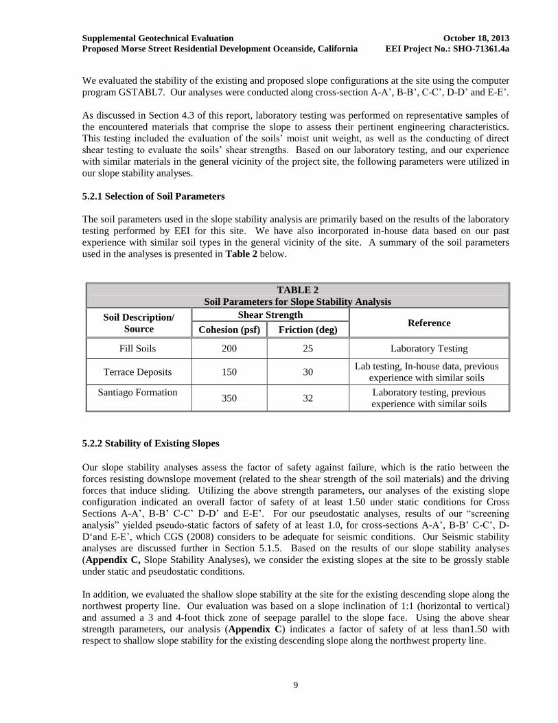
We evaluated the stability of the existing and proposed slope configurations at the site using the computer
program GSTABL7. Our analyses were conducted along cross-section A-A’, B-B’, C-C’, D-D’ and E-E’.
As discussed in Section 4.3 of this report, laboratory testing was performed on representative samples of
the encountered materials that comprise the slope to assess their pertinent engineering characteristics.
This testing included the evaluation of the soils’ moist unit weight, as well as the conducting of direct
shear testing to evaluate the soils’ shear strengths. Based on our laboratory testing, and our experience
with similar materials in the general vicinity of the project site, the following parameters were utilized in
our slope stability analyses.
5.2.1 Selection of Soil Parameters
The soil parameters used in the slope stability analysis are primarily based on the results of the laboratory
testing performed by EEI for this site. We have also incorporated in-house data based on our past
experience with similar soil types in the general vicinity of the site. A summary of the soil parameters
used in the analyses is presented in Table 2 below.
TABLE 2
Soil Parameters for Slope Stability Analysis
Soil Description/
Source
Shear Strength Reference
Cohesion (psf) Friction (deg)
Fill Soils 200 25 Laboratory Testing
Terrace Deposits 150 30 Lab testing, In-house data, previous
experience with similar soils
Santiago Formation
350 32
Laboratory testing, previous
experience with similar soils
5.2.2 Stability of Existing Slopes
Our slope stability analyses assess the factor of safety against failure, which is the ratio between the
forces resisting downslope movement (related to the shear strength of the soil materials) and the driving
forces that induce sliding. Utilizing the above strength parameters, our analyses of the existing slope
configuration indicated an overall factor of safety of at least 1.50 under static conditions for Cross
Sections A-A’, B-B’ C-C’ D-D’ and E-E’. For our pseudostatic analyses, results of our “screening
analysis” yielded pseudo-static factors of safety of at least 1.0, for cross-sections A-A’, B-B’ C-C’, D-
D‘and E-E’, which CGS (2008) considers to be adequate for seismic conditions. Our Seismic stability
analyses are discussed further in Section 5.1.5. Based on the results of our slope stability analyses
(Appendix C, Slope Stability Analyses), we consider the existing slopes at the site to be grossly stable
under static and pseudostatic conditions.
In addition, we evaluated the shallow slope stability at the site for the existing descending slope along the
northwest property line. Our evaluation was based on a slope inclination of 1:1 (horizontal to vertical)
and assumed a 3 and 4-foot thick zone of seepage parallel to the slope face. Using the above shear
strength parameters, our analysis (Appendix C) indicates a factor of safety of at less than1.50 with
respect to shallow slope stability for the existing descending slope along the northwest property line.

Supplemental Geotechnical Evaluation October 18, 2013
Proposed Morse Street Residential Development Oceanside, California EEI Project No.: SHO-71361.4a
10
5.2.3 Stability of Cut Slopes
Review of the rough grading plans for the project indicates that cut slopes up to 20- feet in height with
gradients of 2:1 (horizontal to vertical) or flatter are planned.
Slope stability analyses were performed on representative cross-sections that were constructed through
the proposed cut slopes at various locations across the proposed development (cross-sections C-C’
through D-D’-Figures 6 and 7). Our analyses were based on the proposed post-grading configuration of
the site. Our initial evaluations, which are based on the geological conditions exposed during our
subsurface exploration indicate that the proposed southerly facing cut slopes at the site (in the vicinity of
cross-sections C-C’ and D-D’) will possess a factor of safety of at least 1.5 at the completion of grading.
5.2.4 Stability of Fill Slopes
Based on the results of our laboratory testing and experience with similar soil types in nearby areas,
proposed 2:1 fill slopes constructed with the onsite soils in accordance with the grading requirements
presented in this report will have calculated factors of safety in excess of 1.5 for the maximum slope
heights of 25 feet (Appendix C).
5.2.5 Surficial Slope Stability
In addition, we evaluated the shallow slope stability at the site. Our evaluation was based on a slope
inclination of 2:1 (horizontal to vertical) and assumed a 4-foot thick zone of seepage parallel to the slope
face. Using the above shear strength parameters for fill soils, our analyses indicate a factor of safety of at
least 1.50 with respect to shallow slope stability (Appendix C).
5.2.6 Seismic Slope Stability
EEI’s stability analysis of the existing slope and proposed cut and fill slopes also included an evaluation
of the slope’s stability when subjected to seismic loading. Our seismic evaluation utilized the pseudo-
static procedures described in CGS’ Special Publication 117A (CGS, 2008), where a seismic coefficient
was determined based on site-specific ground motion parameters and a “screening analysis” was
performed to evaluate whether a more involved displacement analysis is warranted (Bray, et. al, 1998;
Blake, et. al, 2002; Stewart, et. al, 2003). Results of our “screening analysis” yielded pseudo-static
factors of safety of at least 1.0, for cross-sections A-A’, B-B’ C-C’, D-D‘and E-E’, which CGS (2008)
considers to be adequate for seismic conditions.
5.3 CONCLUSIONS
Based on our field exploration, laboratory testing and engineering and geologic analysis, it is our opinion
that the site is suitable for the proposed residential development from a geotechnical engineering and
geologic viewpoint; however, there are existing geotechnical conditions associated with the property that
will warrant mitigation and/or consideration during planning stages. If site plans and/or the proposed
building locations are revised, additional field studies may be warranted to address proposed site-specific
conditions. As a result, EEI is providing the following conclusions:

Supplemental Geotechnical Evaluation October 18, 2013
Proposed Morse Street Residential Development Oceanside, California EEI Project No.: SHO-71361.4a
11
• A total of nine exploratory hollow stem auger (HSA) borings were advanced within the subject
property during this evaluation. HSA borings extended to a maximum depth of approximately 36
feet below the existing ground surface (bgs). Overall, the subject property is underlain by
Quaternary aged Terrace Deposits which are in turn underlain by Eocene aged sedimentary
deposits mapped as the Santiago Formation. The Terrace Deposits are mantled by fill and topsoil
deposits that appear to have an approximate thicknesses on the order of two to five feet. Refusal
was not encountered within any of our exploratory borings to the total depths explored.
• Groundwater was not encountered in any of our exploratory borings to the maximum depths
explored of 36 feet below existing grades. However, it should be noted that variations in
groundwater including perched water zones and seepage may result from fluctuations in the
ground surface topography, subsurface stratification, precipitation, irrigation and other factors
that may not have been evident at the time of our subsurface exploration.
• The existing northwest facing slope that descends from the north side of the property appears to
be graded to inclinations of approximately 1.5:1 (horizontal to vertical), with localized portions
that appear steeper, along with observed areas that are apparently over steepened in part due to
past surficial failures. These slopes appear to be at inclinations that are steeper than current CBC
and City of Oceanside grading requirements allow for cut and fill slopes. Our slope stability
analyses indicate that a portion of the slope possesses a factor of safety of less than 1.5 for
surficial stability. It is our understanding that property line constraints and existing residential
development along the base of the slope precludes any grading to achieve overall flatter gradients
along this slope. Refer to Section 7.3 for recommendations related to structural setbacks.
• Laboratory test results indicate that native materials are moderately alkaline (pH = 7. 9) and are
highly corrosive to ferrous metals with minimum resistivity values ranging from 1,120 ohm-cm to
2,700 ohm-cm. Laboratory testing of the upper soils yielded soluble sulfate concentrations
ranging from 52 mg/kg to 131 mg/kg, and chloride concentrations ranging from 13 mg/kg to 17
mg/kg, indicating a negligible corrosion potential to concrete. Concentrations of nitrate in the
soil were reported as ranging from 5.8 mg/kg to 7.3 mg/kg, with a maximum ammonium
concentration reported to be 7.0 mg/kg. These tested levels of ammonium and nitrate do not
appear to pose a corrosion potential to copper piping. It is recommended that a corrosion
engineer be consulted to provide recommendations for proper protection of buried metal pipes at
this site (if warranted).
• The subject property is located within an area of southern California recognized as having a
number of active and potentially-active faults located nearby. Our review indicates that there are
no known active faults mapped as crossing the site and the site is not located within an
Earthquake Fault Zone. The nearest active faults that could affect the subject site include the
offshore segment of the Newport Inglewood Fault Zone, located approximately four miles from
the site, and the Rose Canyon Fault, located approximately five miles from the site. Other nearby
seismic sources includes the Coronado Bank Fault, located approximately 21 miles from the site,
and the Temecula and Julian segments of the Elsinore Fault Zone located approximately 24 and
25 miles, respectively, from the site. Each of these active faults is capable of generating severe
ground shaking at the site.
• Based on EEI’s geotechnical evaluation, earth materials underlying the site of the proposed
residential development are not considered susceptible to liquefaction or significant amounts of
seismic settlement.

Supplemental Geotechnical Evaluation October 18, 2013
Proposed Morse Street Residential Development Oceanside, California EEI Project No.: SHO-71361.4a
12
• Results of our Expansion Index laboratory testing of the upper soils indicate a low to medium
expansion potential.
• A conventional shallow foundation system appears to be suitable for use to support the structures
proposed for residential development, provided the property is graded and improved in general
conformance with guidelines presented herein, as well as the California Building Code (CBC,
2010), the City of Oceanside grading ordinances.
• EEI evaluated static settlement utilizing results of laboratory testing and subsurface data to
estimate settlement as a result of grading the pads to a proposed finish slab grade, with a minor
change in the proposed slab grade elevation from existing grade. Based upon our evaluation and
our recommendations for complete removal of potentially compressible soils within the proposed
building footprints (as presented herein); EEI estimates total static settlement of less than 1-inch
within the building envelope. Differential settlement is estimated to be approximately ½-inch or
less over a distance of 50 feet.
6.0 RECOMMENDATIONS
The recommendations presented herein should be incorporated into the planning and design phases of
development. Guidelines for site preparation, earthwork, and onsite improvements are provided in the
following sections.
6.1 General
Grading should conform to the guidelines presented in the California Building Code, 2010 (CBC, 2010)
and the grading ordinances of the City of Oceanside. Additionally, general Earthwork and Grading
Guidelines are provided herein as Appendix C.
During earthwork construction, removals, excavations, as well as general grading procedures of the
contractor should be observed and the fill placed selectively tested by representatives of the geotechnical
engineer, EEI. If any unusual or unexpected conditions are exposed in the field, they should be reviewed
by the geotechnical engineer and if warranted, modified and/or additional remedial recommendations will
be offered. Specific guidelines and comments pertinent to the planned development are provided herein.
The recommendations presented herein, have been completed using the information provided to us
regarding site development. If information concerning the proposed development is revised, or any
changes in the design and location of the proposed property improvements are made, the conclusions and
recommendations contained in this report should not be considered applicable unless the changes are
reviewed and conclusions of this report modified or approved in writing by this office.
6.2 Site Preparation and Grading
Debris and other deleterious material, such as organic soils and/or environmentally impacted earth
materials should be removed from the site prior to the start of grading. Areas to receive fill should be
properly benched in accordance with current industry standards of practice and guidelines specified in the
CBC, 2010.

Supplemental Geotechnical Evaluation October 18, 2013
Proposed Morse Street Residential Development Oceanside, California EEI Project No.: SHO-71361.4a
13
Existing utilities should be completely removed within the proposed building envelopes. Abandoned
trenches should be properly backfilled and tested. If unanticipated subsurface improvements (utility lines,
septic systems, wells, utilities, etc.) are encountered during earthwork construction, the geotechnical
engineer should be informed and appropriate remedial recommendations would then be provided.
6.3 Remedial Earthwork
Fill and/or topsoil were encountered in each of our exploratory borings that were drilled across the site.
These surficial materials were encountered to depths of between 2 and 5 feet below existing grades.
These materials were relatively loose and are considered potentially compressible. As such, they are
considered unsuitable for the support of settlement-sensitive structures or additional fill in their current
condition. Therefore, where they are not already removed by the proposed site grading, any existing fill
and topsoil should be completely removed and replaced with properly compacted fill in the areas
proposed for construction.
Following removal of the upper soils, the bottom of the resulting excavation(s) should be observed by a
representative of EEI to check that unsuitable materials have been sufficiently removed. It should be
understood that based on the observations of our field representative, localized deeper removals may be
recommended. Some areas may encounter thicker zones of topsoil or fill based on actual field conditions
encountered during earthwork.
The base of the removal areas should be level to avoid differential fill thicknesses under proposed
improvements. This remedial earthwork should extend at least five feet outside the proposed building
limits and/or five feet beyond the area to receive fill. Note that vertical sides exceeding five feet in depth
may be prone to sloughing and may require laying back to an inclination of 1:1 (horizontal to vertical).
After removal of the upper soils and observation of the excavation bottoms, the over-excavated areas
should be scarified to a minimum depth of 8-inches, moisture conditioned as needed to achieve at least
optimum moisture content and re-compacted to at least 90 percent of the maximum dry density (based on
ASTM D1557). The over-excavated areas should then be backfilled with onsite and/or imported soils that
are placed and compacted as recommended herein until design finish grades are reached.
6.4 Cut-Fill Transition and Cut Lots
It is recommended that where cut-fill transitions (daylight) are planned across any of the proposed lots,
the entire cut portion of the daylight pad should be over-excavated to a minimum depth of three feet
below finish grade or 12-inches below the bottoms of the proposed footings (whichever is deeper) and
replaced with compacted fill possessing a very low to low expansion potential. Over-excavation of
transition pads is recommended in order to reduce the potential for differential settlements between cut
and fill transitions. The over-excavation of the transition cut-fill pads should extend at least 5 feet beyond
the proposed building footprints.
In order to provide uniform bearing conditions for any proposed buildings on design cut lots at the site,
we recommend that consideration be given to over-excavation of the pad to a minimum depth of three
feet below finish grade or 12-inches below the bottoms of the proposed footings (whichever is deeper)
and replaced with compacted fill possessing a very low to low expansion potential. This over excavation
should extend at least five feet beyond the proposed building footprints.
Supplemental Geotechnical Evaluation October 18, 2013
Proposed Morse Street Residential Development Oceanside, California EEI Project No.: SHO-71361.4a
14
6.5 Fill Placement
Fill material should possess an expansion index of less than 90 (as determined by ASTM D4829) and be
free of organic matter (less than three percent organics by weight) and other deleterious material. Much
of the onsite materials appear to be suitable for re-use as fill, provided they do not contain rocks greater
than six-inches in maximum dimension, organic debris and other deleterious materials. Rock fragments
exceeding six-inches in one dimension should be segregated and exported from the site, properly placed
in deeper fill areas or utilized for landscaping.
If import soils are needed, the earthwork contractor should ensure that all proposed fill materials are
approved by the geotechnical engineer prior to use. Representative soil samples should be made available
for testing at least ten working days prior to hauling to the site to allow for laboratory tests.
Fill materials should be placed in 6- to 8-inch loose lifts, moisture conditioned as necessary to at least
optimum moisture and compacted to a minimum of 90 percent maximum dry density according to ASTM
D1557. The upper 12-inches of pavement subgrade should be moisture conditioned to at least optimum
moisture and compacted to at least 95 percent of the maximum dry density as determined by ASTM
D1557. Suitable heavy grading equipment should be utilized to properly mix, spread, moisture condition
or dry, and compact each fill lift.
Earthwork may be affected by the existing soil moisture content exceeding optimum. Moist to very moist
earth materials may be difficult to mix and compact in their native condition, and drying or mixing with
drier soils may be warranted to achieve the recommended relative compaction.
Those areas to receive fill (including over-excavated areas) or surface improvements should be scarified
at least 12-inches, moisture conditioned to at least optimum moisture content and recompacted to at least
90 percent of the maximum dry density (based on ASTM D1557).
6.6 Shrinkage and Bulking
Several factors will impact earthwork balancing on the site, including shrinkage, bulking, subsidence,
trench spoils from utilities and footing excavations, and final pavement section thickness as well as the
accuracy of topography.
Shrinkage, bulking and subsidence are primarily dependent upon the degree of compactive effort
achieved during construction. For planning purposes, the shrinkage factor is estimated to be on the order
of 10 to 15 percent for the existing fill/topsoil’s materials to be re-utilized as engineered fill. These
shrinkage factors may vary with methods employed by the contractor. Subsidence is estimated to be on
the order of 0.1 feet. Losses from site clearing and removal of existing site improvements may affect
earthwork quantity calculation and should be considered.
The previous estimates are intended as an aid for the project engineers in estimating earthwork quantities.
It is recommended that the site development be planned to include an area that could be raised or lowered
to accommodate final site balancing.

Supplemental Geotechnical Evaluation October 18, 2013
Proposed Morse Street Residential Development Oceanside, California EEI Project No.: SHO-71361.4a
15
6.7 Graded Slopes
Based on our laboratory test results and our experience with similar earth materials, proposed cut and fill
slopes using onsite materials are expected to be grossly and surficially stable, provided the
recommendations contained herein are implemented during site development. All slopes should be
designed and constructed in accordance with the minimum requirements of the 2010 CBC and/or City of
Oceanside and the following recommendations:
Proposed cut slopes should be constructed at maximum gradients of 2:1 (horizontal to vertical) or
flatter.
Proposed fill slopes should be constructed at a maximum 2:1 gradient (horizontal to vertical) or
flatter.
Fill slope keys should be excavated into properly compacted, engineered fill materials or
competent formational soils approved by the geotechnical engineer and/or geologist. Keyways
should be at least 12 feet in width, extend at least two feet into competent materials and sloped
away from the face-of-slope (i.e., into slope) a minimum of two percent (toe to heel). Depth of
keyways should be based upon field conditions encountered during grading; however, the
minimum depth should be below surficial soils and old existing fills, if present. Fill slopes
should be properly built utilizing horizontal lifts compacted to a minimum relative compaction of
90 percent (ASTM D-1557) throughout, including slope surfaces. If fill slopes are built to grade,
the slope face should be track-walked by a dozer at least every three feet in elevation. As an
option, the fill slope face may be over-built at least 3 feet and trimmed back to grade.
All stormwater facilities (including pervious pavement areas) should be designed to avoid direct
infiltration and saturation near planned slopes. Direct infiltration and saturation should not be
allowed to occur within a minimum horizontal distance to the top of slope equal to the slope
height (i.e., for a 20 foot high slope, setback is at least 20 feet from top of slope).
While stabilization of the planned slopes is not anticipated, locally adverse geologic/geotechnical
conditions (i.e., loose granular cohesionless soils, adversely oriented bedding or discontinuities or
severely weathered soils) may be encountered which may require remedial grading or laying back of the
slope to an angle flatter than the adverse geologic condition. Should any of these materials or conditions
be exposed during construction, EEI’s geotechnical engineer/engineering geologist would assess the
magnitude and extent of the materials and their potential effect on long-term maintenance or possible
slope failures. Recommendations would then be made at the time of the field observation.
7.0 PRELIMINARY FOUNDATION RECOMMENDATIONS
7.1 General
In the event that plans concerning the proposed structures are revised in the project design and/or location
or loading conditions of the planned structure are made, conclusions and recommendations contained in
this report should not be considered valid unless they are reviewed, revised and/or approved in writing by
EEI. The foundation recommendations provided herein are based on the soil materials near finish grade
possessing a low expansion potential (EI < 50). While the foundation design recommendations contained
herein anticipate the use of conventional shallow foundations, options for post tensioned slab foundation
systems can also be provided upon request.

Supplemental Geotechnical Evaluation October 18, 2013
Proposed Morse Street Residential Development Oceanside, California EEI Project No.: SHO-71361.4a
16
Recommendations by the project's design-structural engineer or architect may exceed the following
minimum recommendations. Final foundation design should be provided based on the expansion
potential of the near surface soils encountered during grading
7.2 Foundation Design
The proposed residential structures can be supported on conventional continuous or isolated spread
footings bearing entirely upon firm natural materials (i.e., competent alluvial deposits) or at least 12-
inches of properly compacted fill materials. Foundations supporting buildings up to three stories in
height should be constructed with an embedment of at least 24-inches below finish grade. At these
depths, footings may be designed for an allowable soil bearing value of 2,000 psf. This value may be
increased by one-third for loads of short duration, such as wind and seismic forces. Continuous footings
supporting three-story structures should have minimum widths of 18-inches. Based on geotechnical
considerations, footings should be provided with a minimum reinforcement consisting of two No. 5 rebar,
one top and one bottom. We recommend a minimum width of 24-inches for isolated spread footings.
In order to help reduce the potential for misalignment of proposed garage door openings, we recommend
a grade beam be provided at each garage door opening. This grade beam should be designed in
accordance with the structural engineer’s requirements and have a minimum reinforcement of two No. 4
rebar (one top and one bottom).
Horizontal loads acting on foundations and stem walls cast in open excavations against undisturbed native
soil or against properly placed and compacted fill will be resisted by friction acting along the base of the
footing and by passive earth pressures against the side of the footing and stem wall. The frictional
resistance acting along the base of footings founded on suitable foundation soils may be computed using a
coefficient of friction equal to 0.25 with the normal dead load. Passive earth pressures acting against the
side of footings and stem walls may be assumed to be equivalent to a fluid weighing 250 pounds per
cubic foot. Passive pressure in the upper 1.0-foot should be neglected unless confined by concrete slabs-
on-grade or asphaltic pavement. The values given above may be increased by one-third for transient wind
or seismic loads.
7.3 Footing Setbacks
We recommend that no building structures be planned within 20 feet of the top of the existing northwest
facing, descending slope along the north side of the property without slope re-construction to flatter
gradients or deepened foundations. At a minimum, structural setbacks are recommended for the
deepening of structure footings so that the footings should maintain, at a minimum, a twenty-foot
horizontal setback from the base of the footing to the descending slope. This distance is measured from
the outside footing face at the bearing elevation.
All footings should maintain a minimum seven-foot horizontal setback from the base of the footing to any
descending slope that is constructed at 2:1 inclinations or flatter. This distance is measured from the
outside footing face at the bearing elevation. Footings should maintain a minimum horizontal setback of
H/3 (H=slope height) from the base of the footing to the descending slope face. This setback distance
should not be less than seven feet and need not be greater than 40 feet.

Supplemental Geotechnical Evaluation October 18, 2013
Proposed Morse Street Residential Development Oceanside, California EEI Project No.: SHO-71361.4a
17
Footings adjacent to unlined drainage swales or underground utilities (if any) should be deepened to a
minimum of six-inches below the invert of the adjacent unlined swale or utilities. This distance is
measured from the footing face at the bearing elevation. Footings for structures adjacent to retaining
walls should be deepened so as to extend below a 1:1 projection from the heel of the wall. Alternatively,
walls may be designed to accommodate structural loads from buildings or appurtenances as described in
the retaining wall section of this report.
7.4 Construction
The following foundation construction considerations are presented as minimum recommendations from a
soils engineering standpoint. Laboratory test results indicate the onsite soils swell (expansion) potential is
low to medium (CBC, 2010). During grading of the site, we recommend that no highly expansive soils
material (i.e., possessing an EI > 50) be placed within 24-inches of finish grade, if possible. Design
parameters provided herein, however, assume that finish grade soil materials will have a low expansion
potential.
Recommendations by the project's design-structural engineer or architect, which may exceed the soils
engineer's recommendations, should take precedence over the following minimum considerations. Final
foundation design should be provided based on the expansion potential of the near surface soils
encountered during grading.
7.5 Concrete Slab-on-Grade
Concrete slabs-on-grade should be a minimum of 4-inches thick. Floor slabs should be suitably
reinforced and jointed (in accordance with Structural Engineer's recommendations) so that a small amount
of independent movement can occur without causing damage. Based on the encountered geotechnical
conditions, we recommend that floor slabs be reinforced with No. 3 bars spaced on 18-inch centers (each
way). The contractor should take the appropriate precautions to make sure that the reinforcement is
placed and maintained within the middle one-third of the slab.
Control joints should be provided to help reduce the potential for random cracking. Slabs should be
underlain by a 4-inch thick capillary break layer consisting of clean sand (Sand Equivalent of at least 30)
or rounded fine gravel (pea gravel). Where moisture condensation is undesirable, the slabs should be
underlain with a minimum 10-mil visqueen membrane, sandwiched between two layers of clean sand
(Sand Equivalent of at least 30) each being at least two inches thick. Care should be taken to adequately
seal all seams and not puncture or tear the membrane. The sand should be proof rolled. To reduce the
potential for buildup of hydrostatic pressures, the free draining material under the slabs should have
positive drainage with no low lying areas (i.e., depressions) created.
It should be noted that the above recommendation is based on soil support characteristics only. The
structural engineer should design the actual slab and beam reinforcement based on actual loading
conditions and possible concrete shrinkage.
Exterior slabs, such as walkways and driveways, can be adequately grade supported on firm natural
materials (i.e., terrace deposits) or documented structural fill, being a minimum of 12-inches in thickness,
placed and compacted in accordance with the recommendations contained herein.
In preparation for slab or flatwork construction, the earthwork contractor should ensure that the onsite
soils have been prepared as recommended and that field density tests have been performed to adequately
document the relative compaction of the structural fill. Preparation of the native soils should be
documented prior to placement of aggregate, structural components and/or fill.

Supplemental Geotechnical Evaluation October 18, 2013
Proposed Morse Street Residential Development Oceanside, California EEI Project No.: SHO-71361.4a
18
Some minor cracking of slabs can be expected due to shrinkage. The potential for this slab cracking can
be reduced by careful control of water/cement ratios in the concrete. The contractor should take
appropriate curing precautions during the pouring of concrete in hot or windy weather to reduce the
potential for cracking of slabs. We recommend that a slipsheet (or equivalent) be utilized if grouted fill,
tile, or other crack-sensitive floor covering is planned directly on concrete slabs. All slabs should be
designed in accordance with structural considerations.
All dedicated exterior flatwork should conform to standards provided by the governing agency including
section composition, supporting material thickness and any requirements for reinforcing steel. Concrete
mix proportions and construction techniques, including the addition of water and improper curing, can
adversely affect the finished quality of the concrete and result in cracking and spalling of the slab. We
recommend that all placement and curing be performed in accordance with procedures outlined by the
American Concrete Institute and/or Portland Cement Association. Special consideration should be given
to concrete placed and cured during hot or cold weather conditions. Proper control joints should be
provided to minimize any damage resulting from shrinkage.
As discussed above, laboratory testing of the upper soils yielded soluble sulfate concentrations ranging
from 52 mg/kg to 131 mg/kg, and chloride concentrations ranging from 13 mg/kg to 17 mg/kg, indicating
a negligible corrosion potential to concrete. As such, Type II cement can be used in concrete elements
that will be in contact with the upper soils.
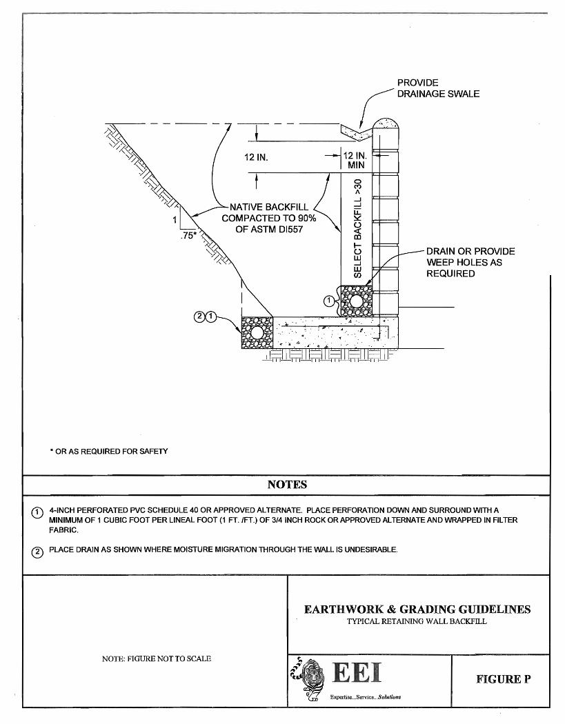
7.6 Retaining Walls
The design parameters provided below assume that non-expansive select material (such as gravel
wrapped in filter fabric) is used to backfill any retaining walls. If expansive soils are used to backfill the
proposed walls, increased active and at-rest earth pressures will need to be utilized for retaining wall
design, and can be provided upon request. Building walls below grade should be waterproofed or damp-
proofed, depending on the degree of moisture protection desired. The foundation system for retaining
walls should be designed in accordance with the recommendations presented in the preceding sections of
this report, as appropriate. Footings should be embedded a minimum of 18-inches below adjacent finish
grade (excluding 6-inch landscape layer). There should be no increase in bearing for footing width.
Recommendations pertaining to “landscape” or MSE walls (i.e., Crib, Loffel, Earthstone, Geogrid, etc.)
may vary from those provided herein, and should be provided upon request.
The design active earth pressure on a retaining wall may be considered equivalent to that produced by a
fluid weighing 40 pounds per cubic foot (pcf). This design equivalent fluid pressure of 40 pcf is
considered appropriate for cantilevered walls retaining non-expansive soils with a level ground surface,
subject to lateral deflection at distances above grade due to lateral earth pressures. A safety factor for
sliding and overturning of 1.5 is typically prescribed for a cantilevered structure as described. All
retaining structures should be fully free draining. Restrained walls (such as basement walls or re-entrant
corners), with a level backfill, should be designed for an equivalent fluid pressure of 60 pcf for at rest
lateral earth pressure. For resistance to lateral loads, an allowable coefficient of friction of 0.25 between
the base of the foundation elements and underlying material is recommended. In addition, an allowable
passive resistance equal to an equivalent fluid weighing 250 pcf acting against the foundation may be
used to resist lateral forces, assuming a level ground surface adjacent to the foundations. Passive pressure
in the upper 1.0-foot should be neglected unless confined by concrete slabs-on-grade or asphaltic
pavement. These values may be increased by one-third for transient wind or seismic loads.
Supplemental Geotechnical Evaluation October 18, 2013
Proposed Morse Street Residential Development Oceanside, California EEI Project No.: SHO-71361.4a
19
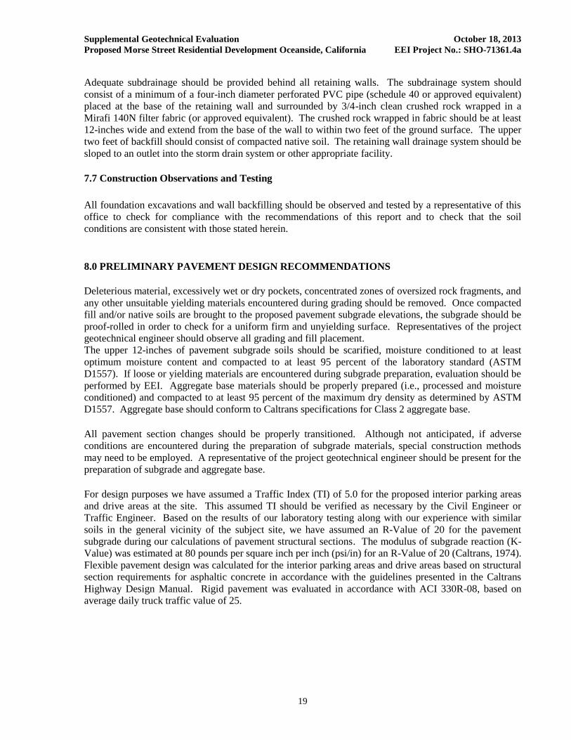
Adequate subdrainage should be provided behind all retaining walls. The subdrainage system should
consist of a minimum of a four-inch diameter perforated PVC pipe (schedule 40 or approved equivalent)
placed at the base of the retaining wall and surrounded by 3/4-inch clean crushed rock wrapped in a
Mirafi 140N filter fabric (or approved equivalent). The crushed rock wrapped in fabric should be at least
12-inches wide and extend from the base of the wall to within two feet of the ground surface. The upper
two feet of backfill should consist of compacted native soil. The retaining wall drainage system should be
sloped to an outlet into the storm drain system or other appropriate facility.
7.7 Construction Observations and Testing
All foundation excavations and wall backfilling should be observed and tested by a representative of this
office to check for compliance with the recommendations of this report and to check that the soil
conditions are consistent with those stated herein.
8.0 PRELIMINARY PAVEMENT DESIGN RECOMMENDATIONS
Deleterious material, excessively wet or dry pockets, concentrated zones of oversized rock fragments, and
any other unsuitable yielding materials encountered during grading should be removed. Once compacted
fill and/or native soils are brought to the proposed pavement subgrade elevations, the subgrade should be
proof-rolled in order to check for a uniform firm and unyielding surface. Representatives of the project
geotechnical engineer should observe all grading and fill placement.
The upper 12-inches of pavement subgrade soils should be scarified, moisture conditioned to at least
optimum moisture content and compacted to at least 95 percent of the laboratory standard (ASTM
D1557). If loose or yielding materials are encountered during subgrade preparation, evaluation should be
performed by EEI. Aggregate base materials should be properly prepared (i.e., processed and moisture
conditioned) and compacted to at least 95 percent of the maximum dry density as determined by ASTM
D1557. Aggregate base should conform to Caltrans specifications for Class 2 aggregate base.
All pavement section changes should be properly transitioned. Although not anticipated, if adverse
conditions are encountered during the preparation of subgrade materials, special construction methods
may need to be employed. A representative of the project geotechnical engineer should be present for the
preparation of subgrade and aggregate base.
For design purposes we have assumed a Traffic Index (TI) of 5.0 for the proposed interior parking areas
and drive areas at the site. This assumed TI should be verified as necessary by the Civil Engineer or
Traffic Engineer. Based on the results of our laboratory testing along with our experience with similar
soils in the general vicinity of the subject site, we have assumed an R-Value of 20 for the pavement
subgrade during our calculations of pavement structural sections. The modulus of subgrade reaction (K-
Value) was estimated at 80 pounds per square inch per inch (psi/in) for an R-Value of 20 (Caltrans, 1974).
Flexible pavement design was calculated for the interior parking areas and drive areas based on structural
section requirements for asphaltic concrete in accordance with the guidelines presented in the Caltrans
Highway Design Manual. Rigid pavement was evaluated in accordance with ACI 330R-08, based on
average daily truck traffic value of 25.

Supplemental Geotechnical Evaluation October 18, 2013
Proposed Morse Street Residential Development Oceanside, California EEI Project No.: SHO-71361.4a
20
TABLE 3
Preliminary Pavement Design Recommendations
Traffic Index (TI) Pavement Surface Aggregate Base Material (1)
5.0 3-inches Asphalt Concrete 7-inches
Trash Area and Concrete Pavement 6-inches Portland Cement Concrete (2) optional
(1) R-Value of 78 for Caltrans Class II aggregate base
(2) Reinforcement and control joints placed in accordance with the structural engineer’s requirements
The recommended pavement sections provided above are intended as a minimum guideline. If thinner or
highly variable pavement sections are constructed, increased maintenance and repair could be expected.
If the ADT (average daily traffic) or ADTT (average daily truck traffic) increases beyond that intended,
as reflected by the assumed and provided traffic indices used for design, increased maintenance and repair
could be required for the pavement section. Final pavement design should be verified by testing of soils
exposed at subgrade after grading has been completed. If the upper three feet of soils are impacted, EEI
may be able to provide a thinner pavement section, assuming soils will have a higher R-Value.
9.0 DEVELOPMENT RECOMMENDATIONS
9.1 Landscape Maintenance and Planting
Water is known to decrease the physical strength of earth materials, significantly reducing stability by
high moisture conditions. Surface drainage away from foundations and graded slopes should be
maintained. Only the volume and frequency of irrigation necessary to sustain plant life should be applied.
Consideration should be given to selecting lightweight, deep rooted types of landscape vegetation which
require low irrigation that are capable of surviving the local climate. From a soils engineering viewpoint,
“leaching” of the onsite soils is not recommended for establishing landscaping. If landscape soils are
processed for the addition of amendments, the processed soils should be re-compacted to at least 90
percent relative compaction (based on ASTM D1557).
9.2 Site Drainage
Positive site drainage should be maintained at all times. Drainage should not flow uncontrolled over
slopes or the subject parcel. Runoff should be channeled away from slopes and structures and not
allowed to pond and/or seep uncontrolled into the ground. Pad drainage should be directed toward an
acceptable outlet. Although not required, roof gutters and down spouts may be considered to control roof
drainage, discharging a minimum of ten feet from the proposed structures, or into a subsurface drainage
system. Consideration should be given to eliminating open bottom planters directly adjacent to proposed
structures for a minimum distance of ten feet. As an alternative, closed-bottom type planters could be
utilized, with a properly designed drain outlet placed in the bottom of the planter.
9.3 Stormwater Disposal Systems
It is EEI understands that current plans call for runoff generated from the facility to be disposed of in
engineered subsurface features onsite.

Supplemental Geotechnical Evaluation October 18, 2013
Proposed Morse Street Residential Development Oceanside, California EEI Project No.: SHO-71361.4a
21
9.3.1 Percolation Testing
During our subsurface exploration at the site, EEI conducted percolation testing in our
exploratory boring B-1A/P-1, and B-2A/P-2which were drilled within accessible areas or near
proposed bioretention areas of the site. Our testing was performed at an approximate depth of
approximately 5 to 10 feet below the existing ground surface. A minimum 2-inch layer of ½-inch
diameter crushed gravel was placed at the bottom of the excavations prior to testing. The
approximate locations of our borings/percolation test are provided on Figure 3.
Percolation testing was conducted by one of EEI’s field geologists under the guidance of a
Registered Engineering Geologist and Registered Civil Engineer with EEI. Percolation test
locations were pre-soaked by pouring at least 5 gallons of water into the excavation. Testing was
started after the holes were allowed to pre-soak for approximately 1 hour. During testing, a
minimum of 12-inches of water was placed in the excavation and the rate of the water drop was
recorded at approximately 10 minute intervals. This procedure was repeated for the test hole until
rates varied generally less than 10 percent for the test hole. We note that a soil profile’s
percolation rate is not the same as its infiltration rate. Therefore, the measured/calculated field
percolation rate was converted to an estimated infiltration rate utilizing a reduction factor known
as the Porchet method (Ritzema, 1974). Upon conclusion of testing, the perforated pipe was
removed and the test excavation was backfilled. Results of percolation testing are presented in
the following table, Table 3.
TABLE 4
Percolation Test Results
Test Boring Depth of Test
(feet below existing grade) Stabilized Percolation Rate
(in/hr) Infiltration Rate (in/hr)
P1 B-1A 5 30 1.31
P2 B-2A 10 15 0.29
9.3.2 Summary of Findings
Based on the results of our percolation testing, it appears that a preliminary infiltration rate of
0.29 inches per hour can be used in preliminary design of subsurface stormwater
retention/disposal devices at the site.
9.3.3 Structural and Slope Setback from Retention Devices
It is recommended that retention/disposal devices be situated at least three times their depth, or a
minimum of 10 feet (whichever is greater), from the outside bottom edge of structural
foundations. Structural foundations include (but are not limited to) buildings, loading docks,
retaining walls, and screen walls.
All stormwater facilities (including pervious pavement areas) should be designed to avoid direct
infiltration and saturation near planned slopes. Direct infiltration and saturation should not be
allowed to occur within a minimum horizontal distance to the top of slope equal to the slope
height (i.e., for a 20 foot high slope, setback is at least 20 feet from top of slope).

Supplemental Geotechnical Evaluation October 18, 2013
Proposed Morse Street Residential Development Oceanside, California EEI Project No.: SHO-71361.4a
22
9.4 Additional Site Improvements
Recommendations for additional grading, exterior concrete flatwork design and construction can be
provided upon request. If in the future, additional property improvements were planned for the site,
recommendations concerning the design and construction of improvements would be provided upon
request.
9.5 Trenching
All temporary excavations for grading purposes and installation of underground utilities should be
constructed in accordance with OSHA guidelines and local safety codes. Temporary excavations over
five feet in height should be evaluated by the project engineer, and could require shoring, sloping, or a
combination thereof. Temporary excavations within the onsite materials should be stable at 1:1
inclinations for cuts less than 10 feet in height.
Footing trench excavations for structures and walls should be observed and approved by a representative
of the project soils engineer prior to placing reinforcement. Footing trench spoil and excess soils
generated from utility trench excavations should be compacted to a minimum relative compaction of 90
percent (based on ASTM D1557) if not removed from the site. All excavations should conform to OSHA
and local safety codes.
9.6 Utility Backfill
Fill around the pipe should be placed in accordance with details shown on the drawings, and should be
placed in layers not to exceed 8-inches loose (unless otherwise approved by the geotechnical engineer)
and compacted to at least 90 percent of the maximum dry density as determined in accordance with
ASTM D1557 (Modified Proctor). The geotechnical engineer should approve all backfill material. Select
material should be used when called for on the drawings, or when recommended by the geotechnical
engineer. Care should be taken during backfill and compaction operations to maintain alignment and
prevent damage to the joints. The backfill should be kept free from stones, chunks of highly plastic clay,
or other objectionable material. Backfill soils should be non-expansive, non-corrosive, and compatible
with native earth materials. Backfill materials and testing should be in accordance with the CBC, 2010,
the City of Oceanside specifications.
Pipe backfill areas should be graded and maintained in such a condition that erosion or saturation will not
damage the pipe bed or backfill. Flooding trench backfill is not recommended. Heavy equipment should
not be operated over any pipe until it has been properly backfilled with a minimum two to three feet of
cover. The utility trench should be systematically backfilled to allow maximum time for natural
settlement. Backfill should not occur over porous, wet, or spongy subgrade surfaces. Should these
conditions exist, the areas should be removed, replaced and recompacted.
10.0 PLAN REVIEW
Once detailed site and grading plans are available, they should be submitted to this office for review and
comment, to reduce the potential for discrepancies between plans and recommendations presented herein.
If conditions were found to differ substantially from those stated, appropriate recommendations would be
provided. Additional field studies may be warranted.
Supplemental Geotechnical Evaluation October 18, 2013
Proposed Morse Street Residential Development Oceanside, California EEI Project No.: SHO-71361.4a
23
11.0 LIMITATIONS
This preliminary due diligence level geotechnical evaluation has been conducted in accordance with
generally accepted geotechnical engineering principles and practices. Findings provided herein have been
derived in accordance with current standards of practice, and no warranty is expressed or implied.
Standards of practice are subject to change with time. This report has been prepared for the sole use of
The Shopoff Advisors, LP, within a reasonable time from its authorization. Site conditions, land use
(both onsite and offsite), or other factors may change as a result of manmade influences, and additional
work may be required with the passage of time.
This evaluation should not be relied upon by other parties without the express written consent of EEI and
the Client; therefore, any use or reliance upon this geotechnical evaluation by a party other than the Client
should be solely at the risk of such third party and without legal recourse against EEI, its employees,
officers, or directors, regardless of whether the action in which recovery of damages is brought or based
upon contract, tort, statue, or otherwise. The Client has the responsibility to see that all parties to the
project, including the designer, contractor, subcontractor, and building official, etc. are aware of this
report in its complete form. This report contains information that may be used in the preparation of
contract specifications; however, the report is not designed as a specification document, and may not
contain sufficient information for use without additional assessment. EEI assumes no responsibility or
liability for work or testing performed by others. In addition, this report may be subject to review by the
controlling authorities.

Supplemental Geotechnical Evaluation October 18, 2013
Proposed Morse Street Residential Development Oceanside, California EEI Project No.: SHO-71361.4a
24
12.0 REFERENCES
American Society of Civil Engineers (ASCE), 2005, Minimum Design Loads for Buildings and Other
Structures, ASCE Document ASCE/SEI 7-05.
American Society for Testing and Materials (ASTM), 2008, Annual Book of ASTM Standards, Volume
04.08, Construction: Soil and Rock (I), Standards D 420 - D 5876.
Blake, T., 2000, “EQFAULT, version 3.0”, a Computer Program for Probabilistic Estimation of Peak
Acceleration from 3-D Fault Sources,” Thomas F. Blake Computer Services and Software, Newbury
Park, California.
Bray, J.D., and Sancio, R.B., 2006, Assessment of the Liquefaction Susceptibility of Fine-Grained
Soils: American Society of Civil Engineers, Journal of the Geotechnical and Geoenvironmental
Engineering, v. 132, n. 9, p. 1165-1177.
California Building Code (CBC), 2010, California Code of Regulations, Title 24, Part 2, Volume 2 of 2,
California Building Standards Commission, Based on 2009 International Building Code; 2010 California
Historical Building Code, Title 24, Part 8; and 2010 California Existing Building Code, Title 24, Part 10,
effective January 1.
California Department of Transportation (Caltrans), 1974, Highway Design Manual, dated October 1,
1974.
California Division of Mines and Geology (CDMG), 1996, S. Tan and M.P. Kennedy, Geologic Maps of
the Northwestern Part of San Diego County, California, Plate 1, Geologic Maps of Oceanside, San Luis
Rey, and San Marcos Quadrangles, DMG Open-File Report 96-02.
California Division of Mines and Geology (CDMG), 2000, California Department of Conservation,
Digital Images of Official Maps of Alquist-Priolo Earthquake Fault Zones of California, Southern
Region, DMG CD 2000-003.
California Division of Mines and Geology (CDMG), 2008, Guidelines for Evaluating and Mitigating
Seismic Hazards in California, Special Publication 117, adopted March 13, 1997, revised and re-adopted
September 11, 2008.
California Geological Survey (CGS), 2002a, Online Interactive Maps, compiled by S. Tan and M.P.
Kennedy, Geologic Map of the Oceanside 30 x 60 Minute Quadrangle, California, Regional Geologic
Map No. 2, 1:100,000 scale,
California Geological Survey (CGS), 2002, California Geomorphic Provinces Note 36, Electronic Copy,
Revised December 2002.
California Geological Survey (CGS), 2008, Guidelines for Evaluating and Mitigating Seismic Hazards in
California, Special Publication 117, revised and re-adopted September 11, 2008.
Coduto, D. P., 2001, Foundation Design Principles and Practices, Second Edition.
DeLORME, 1999, 3-D TopoQuads, California South, Region 7.

Supplemental Geotechnical Evaluation October 18, 2013
Proposed Morse Street Residential Development Oceanside, California EEI Project No.: SHO-71361.4a
25
EEI, 2011, Preliminary Geotechnical Evaluation, Proposed Residential Development, 514 Morse Street,
Oceanside, California, Project No.: SHO- 71361.4, dated November 2, 2011.
Gregory, G.H., 2006, GSTABL7 with STED win Slope Stability Analysis System, Version 2.005, dated
September 2006.
Google Earth®, 2013, Version 6.1.
Hart, E.W., and Bryant, W.A. (Hart and Bryant), 1997, Fault-Rupture Hazard Zones in California:
California Department of Conservation, Division of Mines and Geology, Special Publication 42.
Jennings, C.W., 1994, Fault Activity Map of California and Adjacent Areas: California Division of Mines
and Geology, Map Sheet No. 6, scale 1:750,000.
Jennings, C.W. and Bryant, W.A., 2010, Fault Activity Map of California, California Geological Survey
(CGS), California Geologic Data Map Series, Map No. 6.
O’Day Consultants, Development Plan, Morse Street Townhomes, Sheet 2 of 3, dated October, 2012, plot
date September 27, 2013.
Sowers and Sowers, 1970, Unified Soil Classification System (After U. S. Waterways Experiment Station
and ASTM 02487-667) in Introductory Soil Mechanics, New York.
Stewart, J.P., Blake, T.F. and Hollingsworth, R.A., 2003, A Screen Analysis Procedure for Seismic Slope
Stability: Earthquake Spectra, Vol. 19, No. 3, pp. 697-712.
United States Geological Survey (USGS), 1997, USGS 7.5 Minute Series Topographic Map, San Luis
Rey Quadrangle.
United States Geological Survey (USGS), 2002, Earthquake Hazards Program, Interpolated Probalistic
Ground Motion for the Conterminous 48 States, http://earthquake.usgs.gov/research/hazmaps/design/.
Youd, et.al., 2001, “Liquefaction Resistance of Soils: Summary Report from the 1996 NCEER and 1998
NCEER/NSF Workshops on Evaluation of Liquefaction Resistance of soils”, American Society of Civil
Engineers, Journal of Geotechnical and GeoEnvironmental Engineering, Vol. 127, No. 10, pp. 817-833.

Supplemental Geotechnical Evaluation October 18, 2013
Proposed Morse Street Residential Development Oceanside, California EEI Project No.: SHO-71361.4a
FIGURES
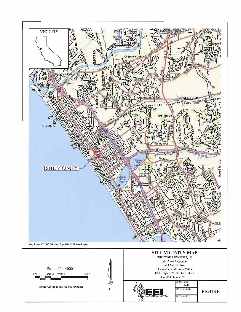


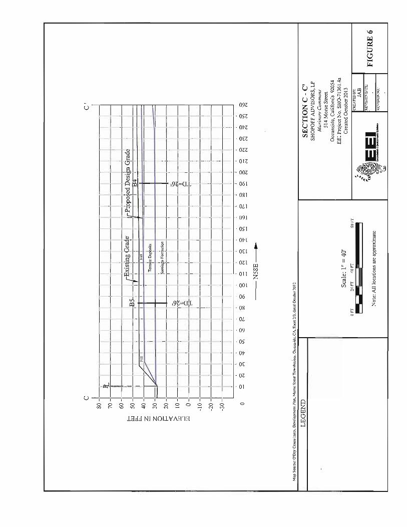
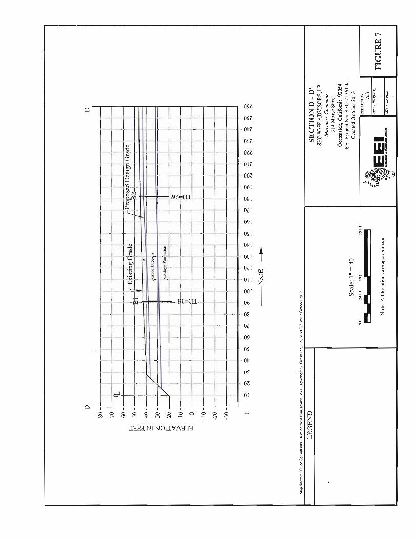

Supplemental Geotechnical Evaluation October 18, 2013
Proposed Morse Street Residential Development Oceanside, California EEI Project No.: SHO-71361.4a
APPENDIX A
SOIL CLASSIFICATION CHART AND BORING LOGS

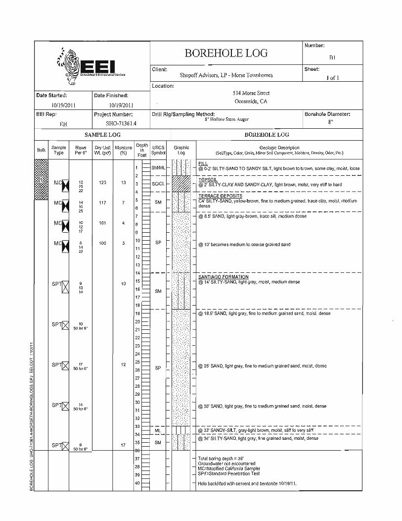

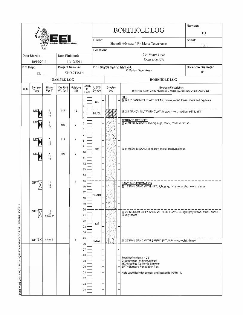

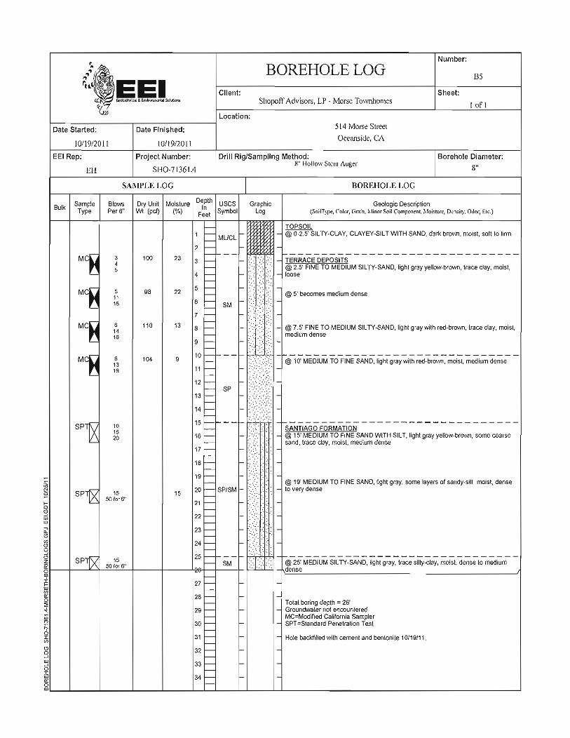


Supplemental Geotechnical Evaluation October 18, 2013
Proposed Morse Street Residential Development Oceanside, California EEI Project No.: SHO-71361.4a
APPENDIX B
LABORATORY TEST DATA


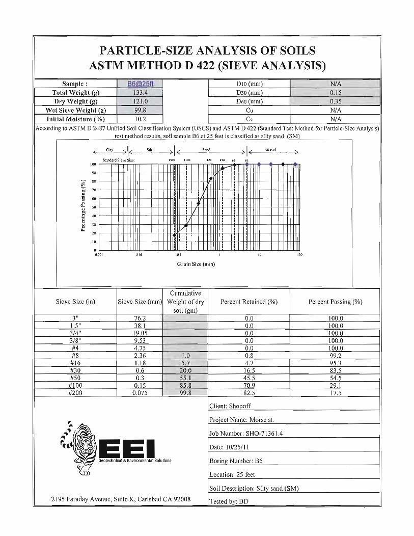
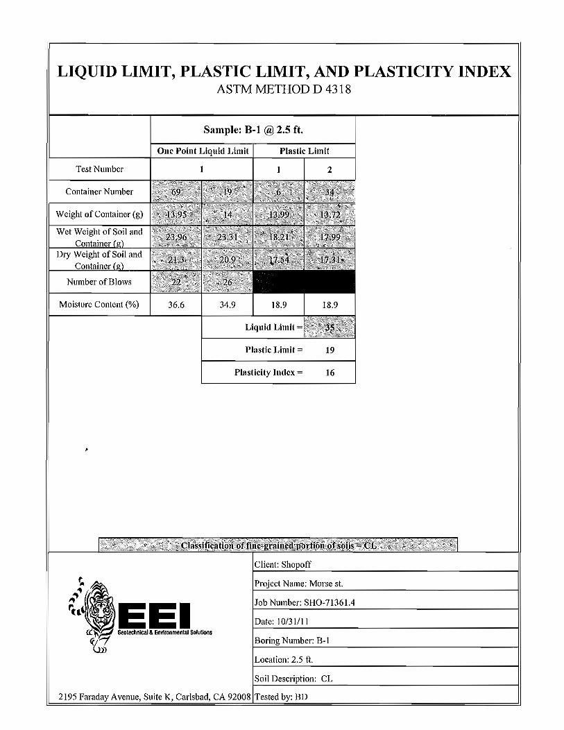


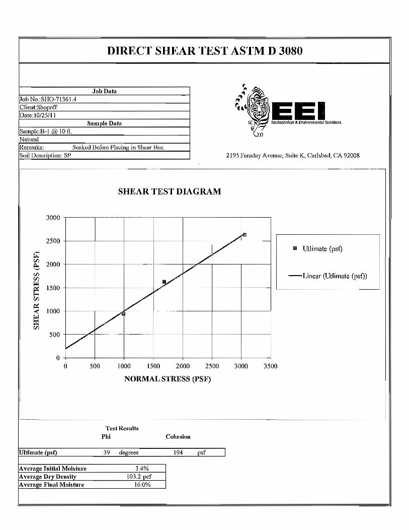


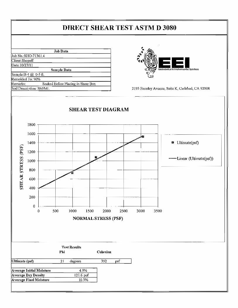

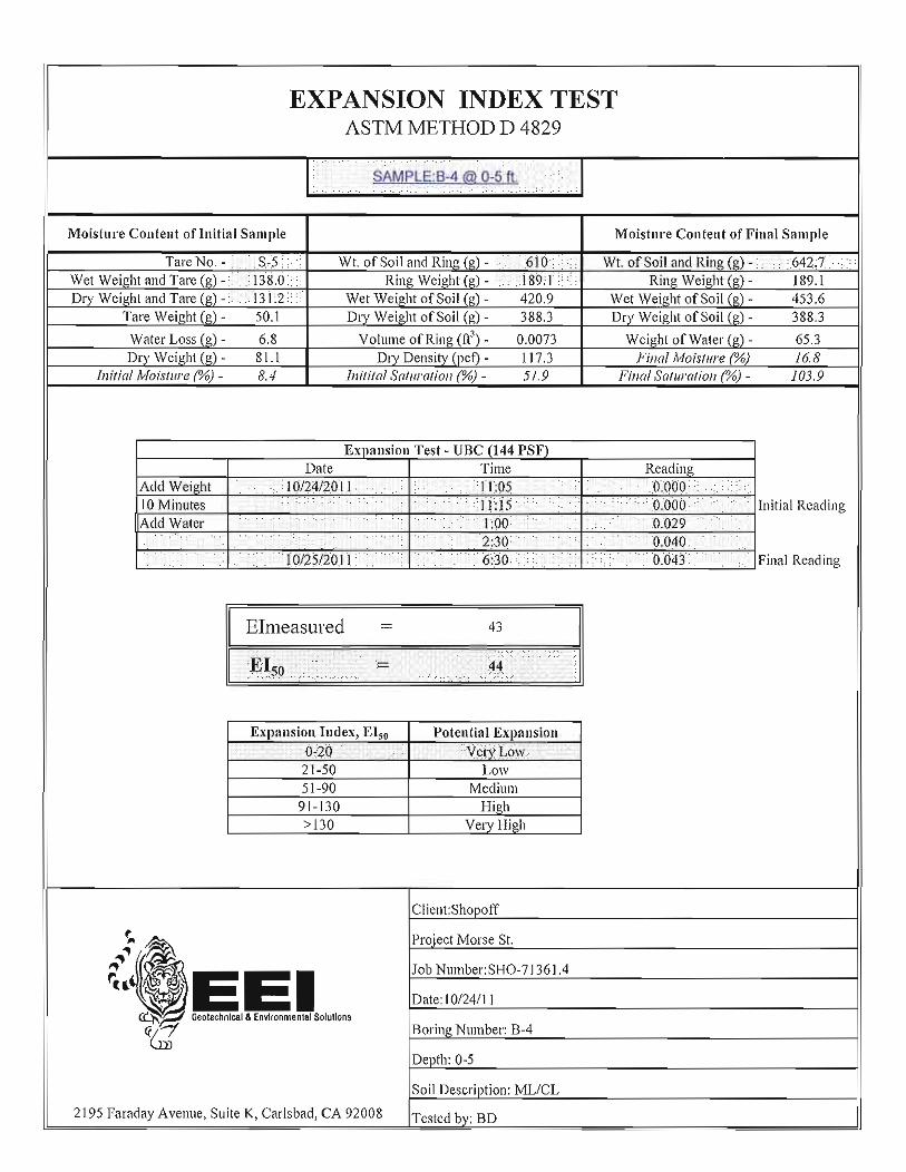


Supplemental Geotechnical Evaluation October 18, 2013
Proposed Morse Street Residential Development Oceanside, California EEI Project No.: SHO-71361.4a
APPENDIX C
SLOPE STABILITY ANALYSES


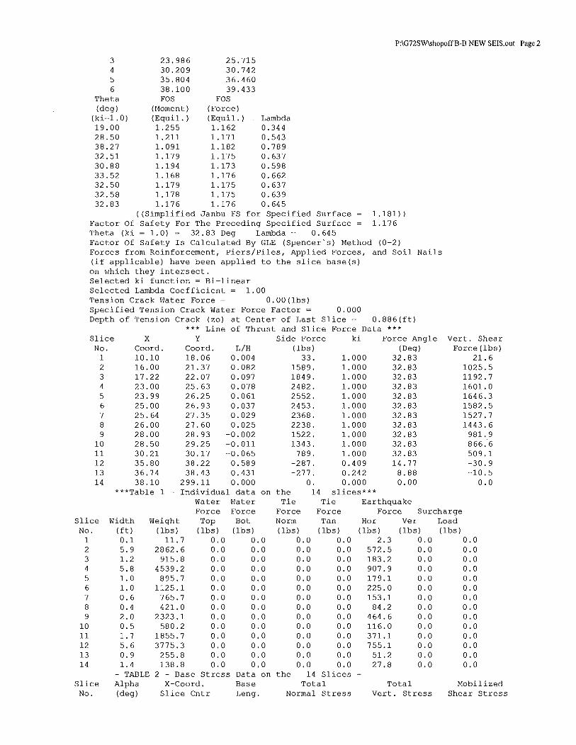
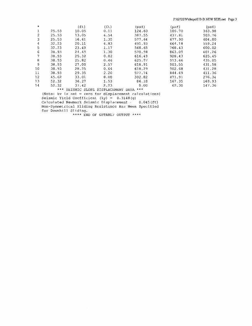


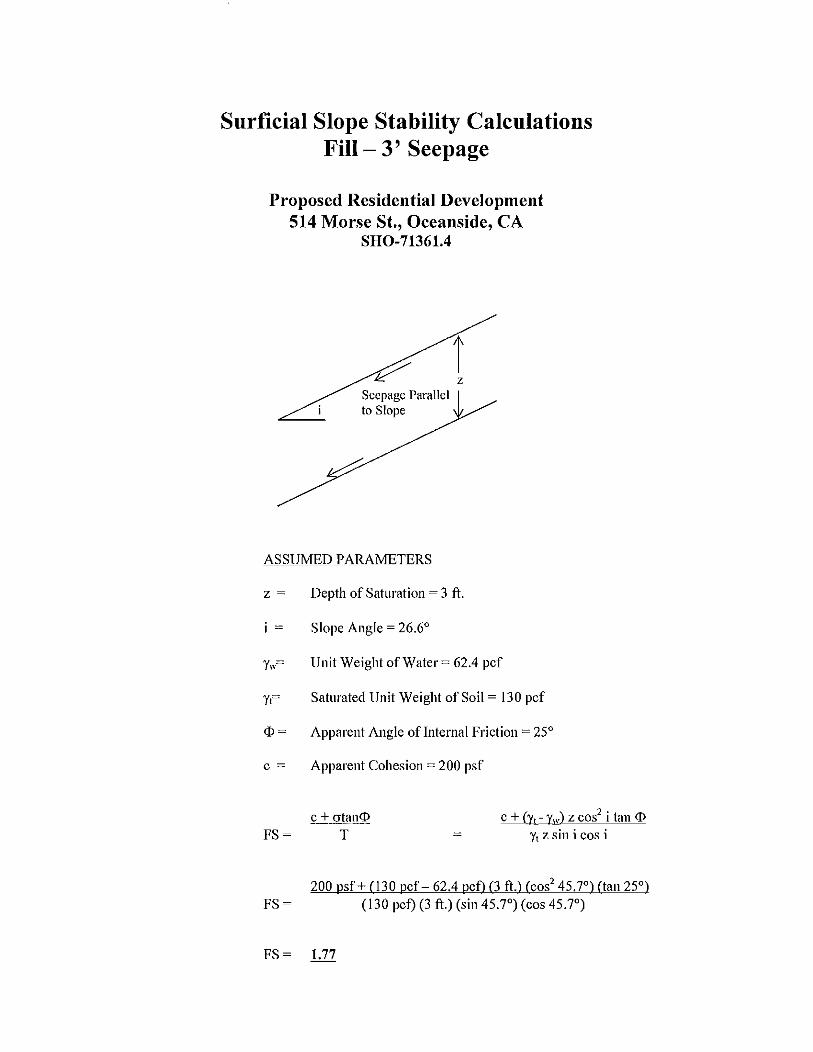


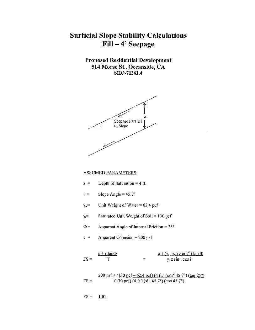


Supplemental Geotechnical Evaluation October 18, 2013
Proposed Morse Street Residential Development Oceanside, California EEI Project No.: SHO-71361.4a
APPENDIX D
EARTHWORK AND GRADING GUIDELINES

2195 Faraday Avenue • Suite K • Carlsbad, California 92008-7207 • Ph: 760-431-3747 • Fax: 760-431-3748 • www.eeitiger.com
EARTHWORK AND GRADING GUIDELINES GENERAL These guidelines present general procedures and recommendations for earthwork and grading as required on the approved grading plans, including preparation of areas to be filled, placement of fill and installation of subdrains and excavations. The recommendations contained in the geotechnical report are applicable to each specific project, are part of the earthwork and grading guidelines and would supersede the provisions contained hereafter in the case of conflict. Observations and/or testing performed by the consultant during the course of grading may result in revised recommendations which could supersede these guidelines or the recommendations contained in the geotechnical report. Figures A through O are provided at the back of this appendix, exhibiting generalized cross sections relating to these guidelines. The contractor is responsible for the satisfactory completion of all earthworks in accordance with provisions of the project plans and specifications. The project soil engineer and engineering geologist (geotechnical consultant) or their representatives should provide observation and testing services, and geotechnical consultation throughout the duration of the project. EARTHWORK OBSERVATIONS AND TESTING Geotechnical Consultant Prior to the commencement of grading, a qualified geotechnical consultant (a soil engineer and engineering geologist) should be employed for the purpose of observing earthwork procedures and testing the fills for conformance with the recommendations of the geotechnical report, the approved grading plans, and applicable grading codes and ordinances. The geotechnical consultant should provide testing and observation so that determination may be made that the work is being completed as specified. It is the responsibility of the contractor to assist the consultant and keep them aware of work schedules and predicted changes, so that the consultant may schedule their personnel accordingly. All removals, prepared ground to receive fill, key excavations, and subdrains should be observed and documented by the project engineering geologist and/or soil engineer prior to placing any fill. It is the contractor’s responsibility to notify the engineering geologist and soil engineer when such areas are ready for observation.

Earthwork and Grading Guidelines
2
Laboratory and Field Tests Maximum dry density tests to determine the degree of compaction should be performed in accordance with American Standard Testing Materials test method ASTM designation D-1557-78. Random field compaction tests should be performed in accordance with test method ASTM designations D-1556-82, D-2937 or D-2922 & D-3017, at intervals of approximately two (2) feet of fill height per 10,000 sq. ft. or every one thousand cubic yards of fill placed. These criteria would vary depending on the soil conditions and the size of the project. The location and frequency of testing would be at the discretion of the geotechnical consultant Contractor’s Responsibility
All clearing, site preparation, and earthwork performed on the project should be conducted by the contractor, with observation by geotechnical consultants and staged approval by the appropriate governing agencies. It is the contractor’s responsibility to prepare the ground surface to receive the fill to the satisfaction of the soil engineer, and to place, spread, moisture condition, mix and compact the fill in accordance with the recommendations of the soil engineer. The contractor should also remove all major deleterious material considered unsatisfactory by the soil engineer. It is the sole responsibility of the contractor to provide adequate equipment and methods to accomplish the earthwork in accordance with applicable grading guidelines, codes or agency ordinances, and approved grading plans. Sufficient watering apparatus and compaction equipment should be provided by the contractor with due consideration for the fill material, rate of placement, and climatic conditions. If, in the opinion of the geotechnical consultant, unsatisfactory conditions such as questionable weather, excessive oversized rock, deleterious material or insufficient support equipment are resulting in a quality of work that is not acceptable, the consultant will inform the contractor, and the contractor is expected to rectify the conditions, and if necessary, stop work until conditions are satisfactory. The contractor will properly grade all surfaces to maintain good drainage and prevent ponding of water. The contractor will take action to control surface water and to prevent erosion control measures that have been installed. SITE PREPARATION All vegetation including brush, trees, thick grasses, organic debris, and other deleterious material should be removed and disposed of offsite, and must be concluded prior to placing fill. Existing fill, soil, alluvium, colluvium, or rock materials determined by the soil engineer or engineering geologist as unsuitable for structural in-place support should be removed prior to fill placement. Depending upon the soil conditions, these materials may be reused as compacted fills. Any materials incorporated as part of the compacted fills should be approved by the soil engineer. Any underground structures such as cesspools, cisterns, mining shafts, tunnels, septic tanks, wells, pipelines, or other structures not located prior to grading are to be removed or treated in a manner recommended by the soil engineer. Soft, dry, spongy, highly fractured, or otherwise unsuitable ground extending to such a depth that surface processing cannot adequately improve the condition should be over excavated down to firm ground and approved by the soil engineer before compaction and filling operations continue. Over excavated and processed soils which have been properly mixed and moisture-conditioned should be recompacted to the minimum relative compaction as specified in these guidelines.

Earthwork and Grading Guidelines
Existing ground which is determined to be satisfactory for support of the fills should be scarified to a minimum depth of six (6) inches, or as directed by the soil engineer. After the scarified ground is brought to optimum moisture (or greater) and mixed, the materials should be compacted as specified herein. If the scarified zone is greater than 6 inches in depth, it may be necessary to remove the excess and place the material in lifts restricted to six (6) inches in compacted thickness. Existing grind which is not satisfactory to support compacted fill should be over excavated as required in the geotechnical report or by the onsite soils engineer and/or engineering geologists. Scarification, discing, or other acceptable form of mixing should continue until the soils are broken down and free of large fragments or clods, until the working surface is reasonably uniform and free from ruts, hollows, hummocks, or other uneven features which would inhibit compaction as described above. Where fills are to be placed on ground with slopes steeper than 5:1 (horizontal to vertical) gradient, the ground should be benched. The lowest bench, which will act as a key, should be a minimum of 12 feet wide and should be at least two (2) feet deep into competent material, approved by the soil engineer and/or engineering geologist. In fill over cut slope conditions, the recommended minimum width of the lowest bench or key is at least 15 feet with the key excavated on competent material, as designated by the Geotechnical Consultant. As a general rule, unless superseded by the Soil Engineer, the minimum width of fill keys should be approximately equal to one-half (½) the height of the slope. Standard benching is typically four feet (minimum) vertically, exposing competent material. Benching may be used to remove unsuitable materials, although it is understood that the vertical height of the bench may exceed four feet. Pre stripping may be considered for removal of unsuitable materials in excess of four feet in thickness. All areas to receive fill, including processed areas, removal areas, and toe of fill benches should be observed and approved by the soil engineer and/or engineering geologist prior to placement of fill. Fills may then be properly placed and compacted until design grades are attained. COMPACTED FILLS Earth materials imported or excavated on the property may be utilized as fill provided that each soil type has been accepted by the soil engineer. These materials should be free of roots, tree branches, other organic matter or other deleterious materials. All unsuitable materials should be removed from the fill as directed by the soil engineer. Soils of poor gradation, undesirable expansion potential, or substandard strength characteristics may be designated unsuitable by the consultant and may require mixing with other earth materials to serve as a satisfactory fill material. Fill materials generated from benching operations should be dispersed throughout the fill area. Benching operations should not result in the benched material being placed only within a single equipment width away from the fill/bedrock contact.
3

Earthwork and Grading Guidelines
Oversized materials, defined as rock or other irreducible materials with a maximum size exceeding 12 inches in one dimension, should not be buried or placed in fills unless the location of materials and disposal methods are specifically approved by the soil engineer. Oversized material should be taken offsite or placed in accordance with recommendations of the soil engineer in areas designated as suitable for rock disposal. Oversized material should not be placed vertically within 10 feet of finish grade or horizontally within 20 feet of slope faces. To facilitate trenching, rock should not be placed within the range of foundation excavations or future utilities unless specifically approved by the soil engineer and/or the representative developers. If import fill material is required for grading, representative samples of the material should be analyzed in the laboratory by the soil engineer to determine its physical properties. If any material other than that previously analyzed is imported to the fill or encountered during grading, analysis of this material should be conducted by the soil engineer as soon as practical. Fill material should be placed in areas prepared to receive fill in near-horizontal layers that should not exceed six (6) inches compacted in thickness. The soil engineer may approve thicker lifts if testing indicates the grading procedures are such that adequate compaction is being achieved. Each layer should be spread evenly and mixed to attain uniformity of material and moisture suitable for compaction. Fill materials at moisture content less than optimum should be watered and mixed, and “wet” fill materials should be aerated by scarification, or should be mixed with drier material. Moisture conditioning and mixing of fill materials should continue until the fill materials have uniform moisture content at or above optimum moisture. After each layer has been evenly spread, moisture-conditioned and mixed, it should be uniformly compacted to a minimum of 90 percent of maximum density as determined by ASTM test designation, D 1557-78, or as otherwise recommended by the soil engineer. Compaction equipment should be adequately sized and should be reliable to efficiently achieve the required degree of compaction. Where tests indicate that the density of any layer of fill, or portion thereof, is below the required relative compaction or improper moisture content, the particular layer or portion will be reworked until the required density and/or moisture content has been attained. No additional fill will be placed in an area until the last placed lift of fill has been tested and found to meet the density and moisture requirements, and is approved by the soil engineer. Compaction of slopes should be accomplished by over-building the outside edge a minimum of three (3) feet horizontally, and subsequently trimming back to the finish design slope configuration. Testing will be performed as the fill is horizontally placed to evaluate compaction as the fill core is being developed. Special efforts may be necessary to attain the specified compaction in the fill slope zone. Final slope shaping should be performed by trimming and removing loose materials with appropriate equipment. A final determination of fill slope compaction should be based on observation and/or testing of the finished slope face.
4

Earthwork and Grading Guidelines
If an alternative to over-building and cutting back the compacted fill slope is selected, then additional efforts should be made to achieve the required compaction in the outer 10 feet of each lift of fill by undertaking the following: • Equipment consisting of a heavy short-shanked sheepsfoot should be used to roll
(horizontal) parallel to the slopes continuously as fill is placed. The sheepsfoot roller should also be used to roll perpendicular to the slopes, and extend out over the slope to provide adequate compaction to the face slope.
• Loose fill should not be spilled out over the face of the slope as each lift is compacted.
Any loose fill spilled over a previously completed slope face should be trimmed off or be subject to re-rolling.
• Field compaction tests will be made in the outer two (2) to five (5) feet of the slope at
two (2) to three (3) foot vertical intervals, subsequent to compaction operations. • After completion of the slope, the slope face should be shaped with a small dozer and
then re-rolled with a sheepsfoot to achieve compaction to near the slope face. Subsequent to testing to verify compaction, the slopes should be grid-rolled to achieve adequate compaction to the slope face. Final testing should be used to confirm compaction after grid rolling.
• Where testing indicates less than adequate compaction, the contractor will be responsible
to process, moisture condition, mix and recompact the slope materials as necessary to achieve compaction. Additional testing should be performed to verify compaction.
• Erosion control and drainage devices should be designed by the project civil engineer in
compliance with the ordinances of the controlling governmental agencies, and/or in accordance with the recommendations of the soil engineer or engineering geologist.
EXCAVATIONS Excavations and cut slopes should be observed and mapped during grading by the engineering geologist. If directed by the engineering geologist, further excavations or over-excavation and refilling of cut areas should be performed. When fills over cut slopes are to be graded, the cut portion of the slope should be observed by the engineering geologist prior to placement of the overlying fill portion of the slope. The engineering geologist should observe all cut slopes and should be notified by the contractor when cut slopes are started. If, during the course of grading, unanticipated adverse or potentially adverse geologic conditions are encountered, the engineering geologist and soil engineer should investigate, evaluate and make recommendations to mitigate (or limit) these conditions. The need for cut slope buttressing or stabilizing should be based on as-grading evaluations by the engineering geologist, whether anticipated previously or not. Unless otherwise specified in soil and geological reports, no cut slopes should be excavated higher or steeper than that allowed by the ordinances of controlling governmental agencies. Additionally, short-term stability of temporary cut slopes is the contractor’s responsibility.
5

Earthwork and Grading Guidelines
Erosion control and drainage devices should be designed by the project civil engineer and should be constructed in compliance with the ordinances of the controlling governmental agencies, and/or in accordance with the recommendations of the soil engineer or engineering geologist. SUBDRAIN INSTALLATION Subdrains should be installed in accordance with the approved embedment material, alignment and details indicated by the geotechnical consultant. Subdrain locations or construction materials should not be changed or modified without approval of the geotechnical consultant. The soil engineer and/or engineering geologist may recommend and direct changes in subdrain line, grade and drain material in the field, pending exposed conditions. The location of constructed subdrains should be recorded by the project civil engineer. COMPLETION Consultation, observation and testing by the geotechnical consultant should be completed during grading operations in order to state an opinion that all cut and filled areas are graded in accordance with the approved project specifications. After completion of grading and after the soil engineer and engineering geologist have finished their observations, final reports should be submitted subject to review by the controlling governmental agencies. No additional grading should be undertaken without prior notification of the soil engineer and/or engineering geologist. All finished cut and fill slopes should be protected from erosion, including but not limited to planting in accordance with the plan design specifications and/or as recommended by a landscape architect. Such protection and/or planning should be undertaken as soon as possible after completion of grading. ATTACHMENTS Figure A – Transition Lot Detail Cut Lot Figure B – Transition Lot Detail Cut - Fill
Figure C – Rock Disposal Pits Figure D – Detail for Fill Slope Toeing out on a Flat Alluviated Canyon Figure E – Removal Adjacent to Existing Fill Figure F – Daylight Cut Lot Detail Figure G – Skin Fill of Natural Ground Figure H – Typical Stabilization Buttress Fill Design Figure I – Stabilization Fill for Unstable Material Exposed in Portion of Cut Slope Figure J – Fill Over Cut Detail Figure K – Fill Over Natural Detail Figure L – Oversize Rock Disposal Figure M – Canyon Subdrain Detail Figure N – Canyon Subdrain Alternate Details Figure O – Typical Stabilization Buttress Subdrain Detail
Figure P – Retaining Wall Backfill
6

5' Minimum
3' Minimum*
Natural Grade
Overexcavate and Recompact
Unweathered Bedrock or Approved Material
Pad Grade
Compacted Fill
Typical Benching
TRANSITION LOT DETAILCUT LOT – MATERIAL TYPE
TRANSITION
* The soils engineer and/or engineering geologist may recommend deeper overexcavation in steep cut-fill transitions.
Note: Figure not to scale Expertise . . Service . . Solutions
EARTHWORK AND GRADING GUIDELINESTRANSITION LOT DETAIL
CUT LOT – MATERIAL TYPE TRANSITION
FIGURE A

Typical Benching
* The soils engineer and/or engineering geologist may recommend deeper overexcavation in steep cut-fill transitions.
5' MinimumNatural Grade
Overexcavate and Recompact
Unweathered Bedrock or Approved Material
Pad Grade
Compacted Fill
TRANSITION LOT DETAILCUT – FILL – DAYLIGHT TRANSITION
Remove: Topsoil, Colluvium, or Unstable Material
3' Minimum*
Note: Figure not to scale
FIGURE BExpertise . . Service . . Solutions
EARTHWORK AND GRADING GUIDELINESTRANSITION LOT DETAIL
CUT – FILL – DAYLIGHT TRANSITION
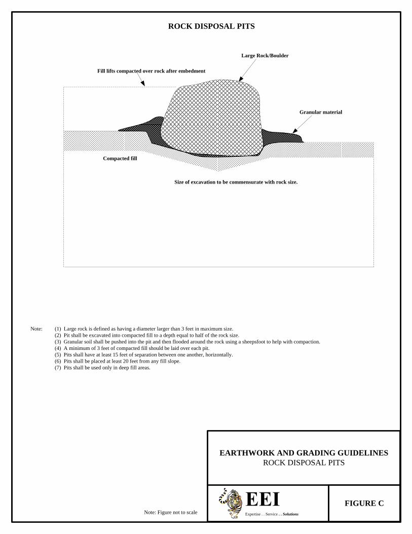
ROCK DISPOSAL PITS
Note: (1) Large rock is defined as having a diameter larger than 3 feet in maximum size.(2) Pit shall be excavated into compacted fill to a depth equal to half of the rock size.(3) Granular soil shall be pushed into the pit and then flooded around the rock using a sheepsfoot to help with compaction.(4) A minimum of 3 feet of compacted fill should be laid over each pit.(5) Pits shall have at least 15 feet of separation between one another, horizontally.(6) Pits shall be placed at least 20 feet from any fill slope.(7) Pits shall be used only in deep fill areas.
Note: Figure not to scale
Size of excavation to be commensurate with rock size.
Compacted fill
Fill lifts compacted over rock after embedment
Granular material
Large Rock/Boulder
Expertise . . Service . . Solutions
EARTHWORK AND GRADING GUIDELINESROCK DISPOSAL PITS
FIGURE C
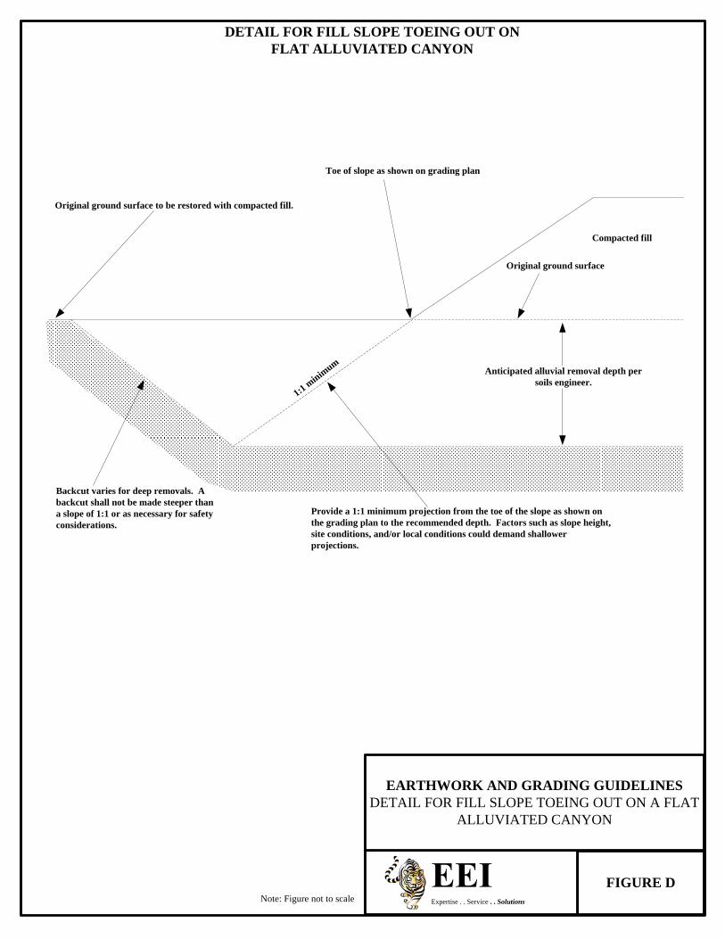
DETAIL FOR FILL SLOPE TOEING OUT ON FLAT ALLUVIATED CANYON
Note: Figure not to scale
Toe of slope as shown on grading plan
Original ground surface to be restored with compacted fill.
Backcut varies for deep removals. A backcut shall not be made steeper than a slope of 1:1 or as necessary for safety considerations.
1:1 minim
um
Compacted fill
Original ground surface
Anticipated alluvial removal depth per soils engineer.
Provide a 1:1 minimum projection from the toe of the slope as shown on the grading plan to the recommended depth. Factors such as slope height, site conditions, and/or local conditions could demand shallower projections.
FIGURE DExpertise . . Service . . Solutions
EARTHWORK AND GRADING GUIDELINESDETAIL FOR FILL SLOPE TOEING OUT ON A FLAT
ALLUVIATED CANYON

REMOVAL ADJACENT TO EXISTING FILL
Note: Figure not to scale
Adjoining Canyon Fill
1:1 Slope
Proposed additional compacted fillCompacted fill limits line
Temporary compacted fill for drainage only
To be removed before placing additional compacted fill
Qaf (Existing compacted fill)Qaf
Qal (To be removed)
Legend
Qaf - Artificial Fill
Qal - Alluvium
FIGURE E
EARTHWORK AND GRADING GUIDELINESREMOVAL ADJACENT TO EXISTING FILL
Expertise . . Service . . Solutions

Note: Figure not to scale
Note: (1) Subdrain and key width requirements shall be determined based on exposed subsurface conditions and the thickness of overburden.
(2) Pad overexcavation and recompaction shall be completed if determined as necessary by the soils engineer and/or engineering geologist.
Expertise . . Service . . Solutions
EARTHWORK AND GRADING GUIDELINESDAYLIGHT CUT LOT DETAIL
FIGURE F
DAYLIGHT CUT LOT DETAIL
Fill slope shall be recompacted at a 2:1 ratio (this may increase or decrease the area of the pad)
Remove: Topsoil, colluvium, or unsuitable material
Overexcavate and recompact fill
Avoid and/or clean up spillage of materials on the natural slope
Natural Grade
Proposed finish grade
3' minimum blanket fill
Bedrock or approved material
Typical benching
2' minimum key depth
Minim
um 1:1 p
rojec
tion
2% gradient
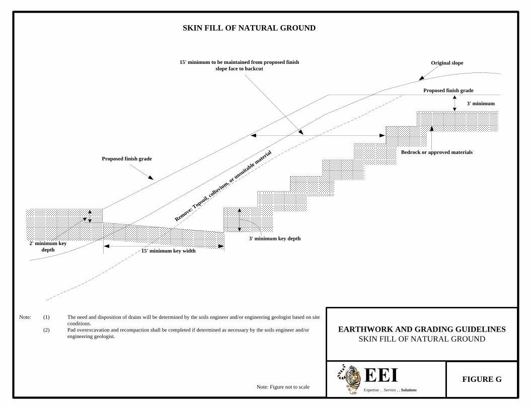
Note: Figure not to scale
Note: (1) The need and disposition of drains will be determined by the soils engineer and/or engineering geologist based on site conditions.
(2) Pad overexcavation and recompaction shall be completed if determined as necessary by the soils engineer and/or engineering geologist.
Expertise . . Service . . Solutions
EARTHWORK AND GRADING GUIDELINESSKIN FILL OF NATURAL GROUND
FIGURE G
SKIN FILL OF NATURAL GROUND
15' minimum key width2' minimum key
depth
3' minimum key depth
3' minimum
Proposed finish grade
Original slope
Proposed finish grade
15' minimum to be maintained from proposed finish slope face to backcut
Remove: T
opsoil, colluvium, or u
nsuitable mater
ial Bedrock or approved materials

Note: Figure not to scale
TYPICAL STABILIZATION BUTTRESS FILL DESIGN
W = H/2 or a minimum of 15'
3' minimum key depth
Bedrock
4" diameter non-perforated outlet pipe and backdrain (see alternatives)
Typical benching
Blanket fill if recommended by the soils engineer and/or engineering geologist
15' minimum
10' minimum25' maximum
Design finish slope
Outlets shall be spaced at 100' maximum intervals, and should extend 12" beyond the face of the slope at the finish of of rough grading
2% gradient
15' is typical
1'-2' clear
Toe Heel
Buttress or sidehill fill
Expertise . . Service . . Solutions
EARTHWORK AND GRADING GUIDELINESTYPICAL STABILIZATION BUTTRESS FILL DESIGN
FIGURE H
Gravel-fabric drain material

Note: Figure not to scale
Note: (1) Subdrains are required only if specified by the soils engineer and/or engineering geologist.(2) “W” shall be the equipment width (15') for slope heights less than 25 feet. For slopes greater than 25 feet “W”
shall be determined by the project soils engineer and/or the engineering geologist. “W” shall never be less than H/2.
Expertise . . Service . . Solutions
EARTHWORK AND GRADING GUIDELINESSTABILIZATION FILL FOR UNSTABLE MATERIAL
EXPOSED IN PORTION OF CUT SLOPE
FIGURE I
STABILIZATION FILL FOR UNSTABLE MATERIAL EXPOSED IN PORTION OF CUT SLOPE
Compacted stabilization fill
H1
H2
W1
W2
1' minimum tilted back
If recommended by the soils engineer and/or engineering geologist, the remaining cut portion of the slope may require removal and replacement with compacted fill.
Remove: unstable material
15' minimum
Remove unstable material
Natural SlopeProposed finished grade
Unweathered bedrock or approved material

Note: Figure not to scale
Note: The cut sectioin shall be excavated and evaluated by the soils engineer/engineering geologist prior to constructing the fill portion.
Expertise . . Service . . Solutions
EARTHWORK AND GRADING GUIDELINESFILL OVER CUT DETAIL
FIGURE J
FILL OVER CUT DETAIL
H
Maintain minimum 15' fill section from backcut to face of finish slope
Proposed gradeCut/Fill Contact: As shown on grading plan
Cut/Fill Contact: As shown on as built
Cut slope
Original topography Remove: Topsoil, colluvium, or unsuitable material
Compacted fill
3' minimum
Lowest bench width15' minimum or H/2
2' minimum
Bedrock or approved material
Bench width may vary
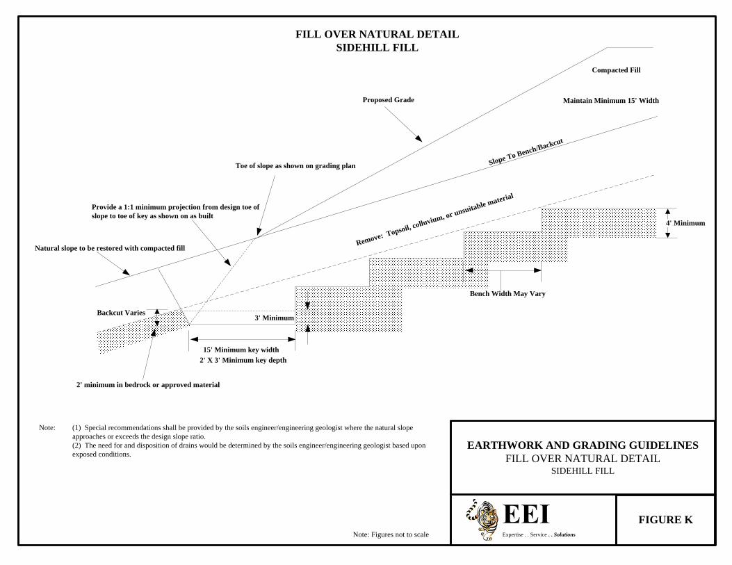
Proposed Grade
Note: Figures not to scale
Compacted Fill
Maintain Minimum 15' Width
Slope To Bench/Backcut
Toe of slope as shown on grading plan
Bench Width May Vary
3' Minimum
15' Minimum key width2' X 3' Minimum key depth
2' minimum in bedrock or approved material
Backcut Varies
Natural slope to be restored with compacted fill
Provide a 1:1 minimum projection from design toe of slope to toe of key as shown on as built
Note: (1) Special recommendations shall be provided by the soils engineer/engineering geologist where the natural slope approaches or exceeds the design slope ratio.(2) The need for and disposition of drains would be determined by the soils engineer/engineering geologist based upon exposed conditions.
Expertise . . Service . . Solutions
EARTHWORK AND GRADING GUIDELINESFILL OVER NATURAL DETAIL
SIDEHILL FILL
FIGURE K
Remove: Topsoil, colluvium, or unsuitable material
4' Minimum
FILL OVER NATURAL DETAILSIDEHILL FILL

OVERSIZE ROCK DISPOSAL
View Normal to Slope Face
Bedrock or Approved Material
Proposed Finish Grade
Note: (1) One Equipment width or a minimum of 15 feet.(2) Height and width may vary depending on rock size and type of equipment used. Length of windrow shall be no greater than 100 feet maximum.(3) If approved by the soils engineer and/or engineering geologist.(4) Orientation of windrows may vary but shall be as recommended by the soils engineer and/or engineering geologist. Unless recommended staggering of windrows is not necessary.(5) Areas shall be cleared for utility trenches, foundations, and swimming pools.(6) Voids in windrows shall be filled by flooding granular soil into place. Granular soil shall be any soil which has a unified soil classification system (Universal Building Code (UBC) 29-1). Designation of SM, SP, SW, GP, or GW.(7) After fill between windrows is placed and compacted with the lift of fill covering windrow, windrow shall be proof rolled with a D-9 dozer or equivalent.(8) Oversized rock is defined as larger than 12", and less than 4 feet in size.
(2)
10' minimum (5)
15' minimum (1)(6)
(7)
5' minimum (3)15' minimum 20' minimum
View Parallel to Slope Face
Bedrock or Approved Material
Proposed Finish Grade
100' maximum
10' minimum (5)(7)
5' minimum (3)
10' minimum
3' minimum (8)
Note: All distances are approximate
0 FT 18 FT 30 FT 60 FT
Approximate Scale: 1" = 30'
(4)
Expertise . . Service . . Solutions
EARTHWORK AND GRADING GUIDELINESOVERSIZE ROCK DISPOSAL
FIGURE L

CANYON SUBDRAIN DETAIL
Note: Alternatives, locations, and extent of subdrains should be determined by the soils engineer and/or engineering geologist during actual grading.
Note: Figures not to scale
Type A
Type B
Proposed Compacted Fill
Natural ground
Colluvium and alluvium (remove)
See alternatives (Figure N)
Typical benching
Proposed Compacted Fill
Natural ground
Colluvium and alluvium (remove)
See alternatives (Figure N)
FIGURE MExpertise . . Service . . Solutions
EARTHWORK AND GRADING GUIDELINESCANYON SUBDRAIN DETAIL
Typical benching

CANYON SUBDRAIN ALTERNATE DETAILS
Alternate 1: Perforated Pipe and Filter Material
Filter material: Minimum volume of 9 feet3/linear foot. 6" diameter ABS or PVC pipe or approved substitute with minimum 8 (¼” diameter) perforations per linear foot in bottom half of pipe. ASTM D 2751, SDR 35 or ASTM D 1527, Schedule 40.ASTM D 3034, SDR 35 or ASTM D 1785, Schedule 40.For continuous run in excess of 500 feet use 8" diameter pipe.
6" Minimum
6" Minimum
6" Minimum
12" Minimum
Alternate 2: Perforated Pipe, Gravel and Filter Fabric
Minimum Overlap
Minimum Bedding
6"
4"
6" Minimum CoverMinimum Bedding 4"
6"
Note: Figures not to scale
Minimum Overlap
Gravel material 9 feet3/linear foot. Perforated pipe: see alternate 1.Gravel: Clean ¾” rock or approved substitute.Filter Fabric: Mirafi 140 or approved substitute.
Filter Material
Sieve Size1"¾”3/8"
No. 4No. 8No. 30No. 50No. 200
Percent Passing100
90-10040-10025-4018-335-150-70-3
FIGURE NExpertise . . Service . . Solutions
EARTHWORK AND GRADING GUIDELINESCANYON SUBDRAIN ALTERNATE DETAILS

Note: Figures not to scale
TYPICAL STABILIZATION BUTTRESS SUBDRAIN DETAIL
4" minimum pipe2' minimum
2" minimum
2" minimum
2' minimum
2" minimum4" minimum pipe
3' minimum
Filter Material: Minimum of 5 ft3/linear foot of pipe or 4 ft3/linear foot of pipe when placed in square cut trench.
Filter Material
Sieve Size1"¾”3/8"
No. 4No. 8
No. 30No. 50No. 200
Percent Passing100
90-10040-10025-4018-335-150-70-3
Note: (1) Trench for outlet pipes shall be backfilled with onsite soil.(2) Backdrains and lateral drains shall be located at the elevation of every bench drain. First drain shall be located at the elevation just above the lower lot grade. Additional drains may be
required at the discretion of the soils engineer and/or engineering geologist.
Alternative In Lieu Of Filter Material: Gravel may be encased in approved filter fabric. Filter fabric shall be mirafi 140 or equivalent. Filter fabric shall be lapped a minimum of 12" on all joints.
Minimum 4" Diameter Pipe: ABS-ASTM D-2751, SDR 35 or ASTM D-1527 schedule 40 PVC-ASTM D-3034, SDR 35 or ASTM D-1785 schedule 40 with a crushing strength of 1,000 pounds minimum, and a minimum of 8 uniformly spaced perforations per foot of pipe installed with perforations at bottom of pipe. Provide cap at upstream end of pipe. Slope at 2% to outlet pipe. Outlet pipe shall be connected to the subdrain pipe with tee or elbow.
Filter Material – Shall be of the following specification or an approved equivalent:
Gravel - Shall be of the following specification or an approved equivalent:
Filter Material
Sieve Size1½"
No. 4No. 200
Percent Passing100508
Sand equivalent: Minimum of 50FIGURE O
EARTHWORK AND GRADING GUIDELINESTYPICAL STABILIZATION BUTTRESS SUBDRAIN
DETAIL
Expertise . . Service . . Solutions