
Suport de curs
„Statica constructiilor – Structural
analysis”
Inginerie civila
Grupa ICE
An de studiu III
2013


1. Flexibility Method
Portal frame – 2 load cases
Load case 1
Degree of static indeterminacy d = l� + r − 3e �� -number of internal links
– number of external links (reactions)
� – number of elements
� = 9 + 4 − 3 ∙ 4 = 1 (considering 4 elements rigidly connected, with 3
internal links between elements)
or � = 0 + 4 − 3 ∙ 1 = 1 (the 4 elements rigidly connected may be seen as a
single body, therefore there are no internal links)
Primary structure
0
Compatibility equation D�� = d�� ∙ X� + D��� = 0 ��� – linear displacement at the point and in the direction of the
redundant horizontal reaction X1, caused by the unit value of X1, acting on
the primary structure;

��� ∙ �� – linear displacement at the point and in the direction of the
redundant horizontal reaction X1, caused by X1, acting on the primary
structure; ���� – linear displacement at the point and in the direction of the
redundant horizontal reaction X1, caused by the external loads, acting on the
primary structure; ��� – linear displacement at the point and in the direction of the
redundant horizontal reaction X1, caused by X1 and by the external loads,
acting on the primary structure; it must be zero, , because in this point and
on the direction of X1, on the real structure exists a link which does not allow
this displacement (pinned support).
Bending moment on the primary structure due to external loads �� H = 0 R"�� = 15kN �� M � = 0 50 ∙ 6 + 15 ∙ 6 − R()� ∙ 12 = 0
(Clockwise is considered positive) ⟹ R()� = 32.5kN �� M ) = 0 R(�� ∙ 12 − 50 ∙ 6 + 15 ∙ 6 = 0 R(�� = 17.5kN Verification �� V = 0 R(�� + R()� − 50kN = 0
M0P
Bending moment on the primary structure due to X1=1 �� H = 0 R"�� = 1 �� M � = 0 R(�� = 0 �� M ) = 0 R()� = 0 EI ∙ d�� = 2 111 ∙ 6 ∙ 2−632 ∙ 23 ∙ 2−63 + 12 ∙ 6.083 ∙ 2−632 ∙ 523 ∙ 2−63 + 13 ∙ 2−736 + 12
∙ 6.083 ∙ 2−732 ∙ 523 ∙ 2−73 + 13 ∙ 2−6367

EI ∙ d�� = 401.514 EI ∙ D��� = 11 ∙ 6 ∙ 902 ∙ 23 ∙ 2−63 + 12 ∙ 6.083 ∙ 902 ∙ 823 ∙ 2−63 + 13 ∙ 2−739 + + 12 ∙ 6.083 ∙ 2102 ∙ 523 ∙ 2−73 + 13 ∙ 2−636 + 12 ∙ 6.083 ∙ 2102 ∙ 523 ∙ 2−73 + 13 ∙ 2−636 EI ∙ D��� = −6204.93 X� = − D���d�� = 15.454 kN
Portal frame with tie
E ∙ I = 1.512 ∙ 10)kNm; E< ∙ A< = 1.4845 ∙ 10)kN
Degree of static indeterminacy (the frame may be considered as having
4 elements rigidly connected each-other by 3 internal links + the tie, hinged
to the frame, thus resulting 2 internal links on each end of the tie): d = l� + r − 3e = 13 + 4 − 3 ∙ 5 = 2
Primary structure
0
Compatibility equations >��� = d�� ∙ X� + d�; ∙ X; + D��� = 0�;� = d;� ∙ X� + d;; ∙ X; + D;�� = −∆l;

��� – linear displacement at the point and in the direction of the
redundant horizontal reaction X1, caused by the unit value of X1, acting on
the primary structure; �;; – linear displacement at the point and in the direction of the
redundant axial force X2, caused by the unit value of X2, acting on the
primary structure; ��� ∙ �� – linear displacement at the point and in the direction of the
redundant horizontal reaction X1, caused by X1, acting on the primary
structure; �;; ∙ �; – linear displacement at the point and in the direction of the
redundant axial force X2, caused by X2, acting on the primary structure; ��; – linear displacement at the point and in the direction of the
redundant horizontal reaction X1, caused by the unit value of X2, acting on
the primary structure; �;� – linear displacement at the point and in the direction of the
redundant axial force X2, caused by the unit value of X1, acting on the
primary structure; ��; ∙ �; – linear displacement at the point and in the direction of the
redundant horizontal reaction X1, caused by X2, acting on the primary
structure �;� ∙ �� – linear displacement at the point and in the direction of the
redundant axial force X2, caused by X1, acting on the primary structure; ���� – linear displacement at the point and in the direction of the
redundant horizontal reaction X1, caused by the external loads, acting on the
primary structure �;�� – linear displacement at the point and in the direction of the
redundant axial force X2, caused by the external loads, acting on the primary
structure; ��� – linear displacement at the point and in the direction of the
redundant horizontal reaction X1, caused by X1, X2 and by the external loads,
acting on the primary structure; it must be zero, because in this point and on
the direction of X1, on the real structure exists a link which does not allow
this displacement; �;� – linear displacement at the point and in the direction of the
redundant axial force X2, caused by X1, X2 and by the external loads, acting
on the primary structure. This displacement is equal to the relative
displacement between points 2 and 4 (∆�;) on the statically indeterminate
structure. The “-“ sign indicates that the displacement produced by the axial
force in the tie (X2) on the statically indeterminate structure, is equal and
opposite to the displacement from the same force X2 acting on the primary
structure. ∆l; = l;@EA ∙ AA ∙ X; where: �;@ – length of the tie C< ∙ D< – axial rigidity of the tie

Bending moment on the primary structure due to X2=1
EI ∙ d�� = 2 111 ∙ 6 ∙ 2−632 ∙ 23 ∙ 2−63 + 12 ∙ 6.083 ∙ 2−632 ∙ 523 ∙ 2−63 + 13 ∙ 2−736 + 12
∙ 6.083 ∙ 2−732 ∙ 523 ∙ 2−73 + 13 ∙ 2−6367 EI ∙ d�� = 401.514 EI ∙ d�; = 2 112 ∙ 6.083 ∙ 2−632 ∙ 813 ∙ 2−139 + 12 ∙ 6.083 ∙ 2−732 ∙ 823 ∙ 2−1397= 20.277 EI ∙ d;; = 2 112 ∙ 6.083 ∙ 2−132 ∙ 823 ∙ 2−1397 = 2.03 EI ∙ D��� = 11 ∙ 6 ∙ 902 ∙ 23 ∙ 2−63 + 12 ∙ 6.083 ∙ 902 ∙ 523 ∙ 2−63 + 13 ∙ 2−736 + 12 ∙ 6.083 ∙ 2102∙ 523 ∙ 2−73 + 13 ∙ 2−636 + 12 ∙ 6.083 ∙ 2102 ∙ 523 ∙ 2−73 + 13 ∙ 2−636 EI ∙ D��� = −6204.93 EI ∙ D;�� = 12 ∙ 6.083 ∙ 902 ∙ 513 ∙ 2−136 + 12 ∙ 6.083 ∙ 2102 ∙ 823 ∙ 2−139 + 12∙ 6.083 ∙ 2102 ∙ 823 ∙ 2−139 EI ∙ D;�� = −471.433

EFGD�� = 401.514EI ∙ X� + 20.277EI ∙ X; − 6204.93EI = 0
D;� = 20.277EI ∙ X� + 2.03EI ∙ X; − 471.433EI = − 12.0EAAA ∙ X; HD�� = 401.514 ∙ X� + 20.277 ∙ X; − 6204.93 = 0D;� = 20.277 ∙ X� + 2.03 ∙ X; − 471.433 = −12 EIEAAA ∙ X;
CIC<D< = 1.512 ∙ 10)kNm;E< ∙ A< = 1.4845 ∙ 10)kN = 1.0165m; �� = 14.852 kN �; = 11.95 kN
Portal frame with inclined elements
Degree of static indeterminacy (the structure may be seen as two bodies
connected by a hinge, thus having 2 internal links): � = �� + − 3� = 2 + 5 − 3 ∙ 2 = 1
- In the first case, the unknown is the moment reaction in point 5:
01
Bending moment on the primary structure due to external loads
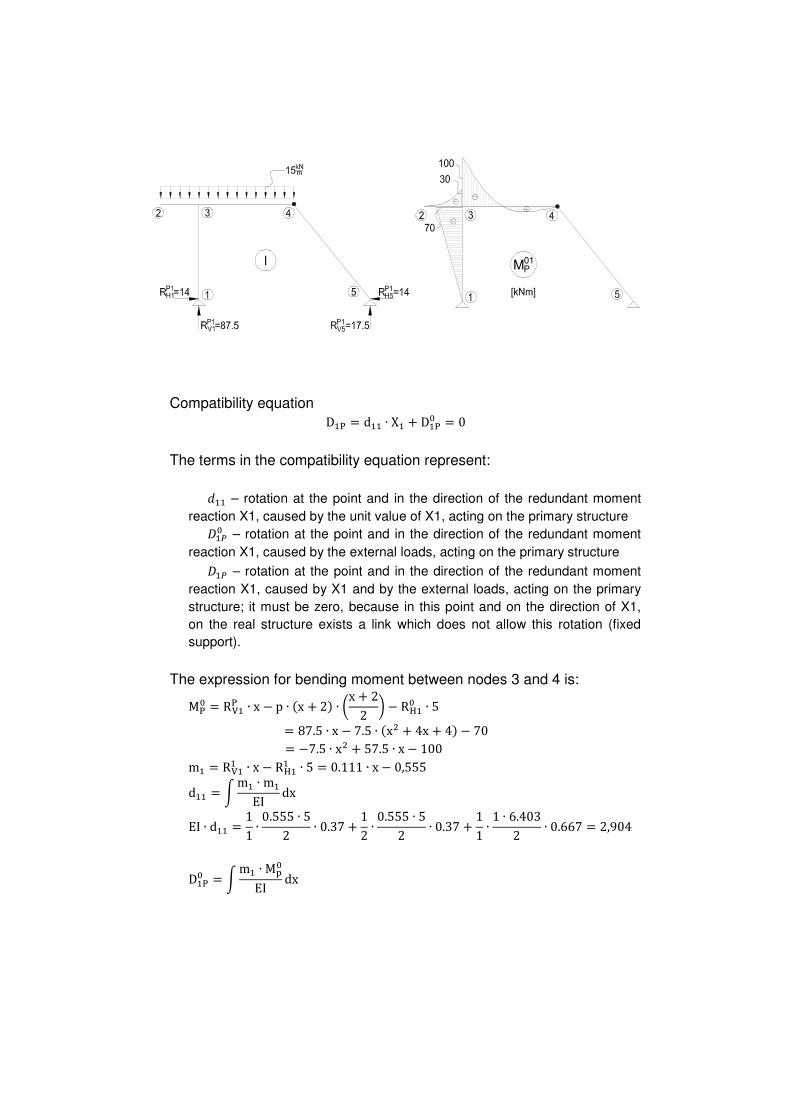
M01P
Compatibility equation D�� = d�� ∙ X� + D��� = 0
The terms in the compatibility equation represent:
��� – rotation at the point and in the direction of the redundant moment
reaction X1, caused by the unit value of X1, acting on the primary structure ���� – rotation at the point and in the direction of the redundant moment
reaction X1, caused by the external loads, acting on the primary structure ��� – rotation at the point and in the direction of the redundant moment
reaction X1, caused by X1 and by the external loads, acting on the primary
structure; it must be zero, because in this point and on the direction of X1,
on the real structure exists a link which does not allow this rotation (fixed
support).
The expression for bending moment between nodes 3 and 4 is: M�� = R(�� ∙ x − p ∙ 2x + 23 ∙ 5x + 22 6 − R"�� ∙ 5= 87.5 ∙ x − 7.5 ∙ 2x; + 4x + 43 − 70 = −7.5 ∙ x; + 57.5 ∙ x − 100 m� = R(�� ∙ x − R"�� ∙ 5 = 0.111 ∙ x − 0,555 d�� = M m� ∙ m�EI dx EI ∙ d�� = 11 ∙ 0.555 ∙ 52 ∙ 0.37 + 12 ∙ 0.555 ∙ 52 ∙ 0.37 + 11 ∙ 1 ∙ 6.4032 ∙ 0.667 = 2,904 D��� = M m� ∙ MN�EI dx

EI ∙ D��� = 11 ∙ −70 ∙ 52 ∙ 23 ∙ 2−0,5553 + 12∙ M 20.111 ∙ x − 0,5553 ∙ 2−7.5 ∙ x; + 57.5 ∙ x − 1003dx)�
EI ∙ D��� = 64.75 + 12 ∙ M 2−0.8325 ∙ xO + 6.3825 ∙ x; − 11.1 ∙ x +)� +4.162 ∙ x; − 31.9125 ∙ x + 55.53dx EI ∙ D��� = 64.75 + 12 ∙ M 2−0.8325 ∙ xO + 10.545 ∙ x; − 43.0125 ∙ x + 55.53dx)�
EI ∙ D��� = 64.75 + 12 ∙ 8−0.8325 ∙ x@4 + 10.545 ∙ xO3 − 43.0125 ∙ x;2 + 55.5 ∙ x9P�)
EI ∙ D��� = 64.75 + 24.57 = 89.32 ⟹ X� = − D���d�� = −30.75 kNm
Symmetric portal frame
Degree of static indeterminacy d = l� + r − 3e = 6 + 6 − 3 ∙ 3 = 3
The structure is symmetric. The load may be decomposed in two load
cases, which will be treated separately: one symmetric and one
antisymmetric.

The deformed shapes of the structure for the two load cases are
symmetric and antisymmetric, respectively. For each load case, in the point
situated in the middle of the beam (in the axis of symmetry of the structure),
some displacements are zero:
In order to simplify the calculation, half of structure may be considered
for both load cases. For the point in the middle of the beam, external links
corresponding to the zero displacements from figures above may be
considered, by means of appropriate supports:
Consequently, the following primary structures may be considered for
the two structures:
0
0
The symmetric structure
Bending moment on the primary structure due to external loads
Bending moment on the primary structure due to X1=1

Bending moment on the primary structure due to X2=1
Compatibility equations >D�� = d�� ∙ X� + d�; ∙ X; + D��� = 0D;� = d;� ∙ X� + d;; ∙ X; + D;�� = 0 EI ∙ d�� = 11 ∙ 4 ∙ 2−432 ∙ 23 ∙ 2−43 = 21.333
EI ∙ d�; = 11 ∙ 4 ∙ 2−432 ∙ 1 = −8 EI ∙ d;; = 11 ∙ 24 ∙ 13 ∙ 1 + 14.612 ∙ 24.5 ∙ 13 ∙ 1 = 4.9757 EI ∙ D��� = 11 ∙ Q4 ∙ 2−121.53R ∙ 12 ∙ 2−43 = 972 EI ∙ D;�� = 11 ∙ Q4 ∙ 2−121.53R ∙ 1 + 14.612 ∙ S13 ∙ 4.5 ∙ 2−121.53T ∙ 1 = −525.516
X� = −15.001 kN X; = 81.497 kNm
The antisymmetric structure
Bending moment on the primary structure due to external loads
Bending moment on the primary structure due to X1=1

Compatibility equations D�� = d�� ∙ X� + D��� = 0 EI ∙ d�� = 11 ∙ Q4 ∙ 2−4.53R ∙ 2−4.53 + 14.612 ∙ 4.5 ∙ 2−4.532 ∙ 23 ∙ 2−4.53 = 87.586
EI ∙ D��� = 11 ∙ S13 ∙ 4 ∙ 2−283T ∙ 2−4.53 = 168 X� = −1.918 kN
2. TRUSSES
Problem 1
2A
2A
2A
2A
A
A
A
AA
A
Degree of static indeterminacy d = b + r − 2 ∙ j = 10 + 3 − 2 ∙ 6 = 1 b - number of bars
- number of external links (reactions)
W - number of joints
Primary structure

Compatibility equation D�� = d�� ∙ X� + D��� = −∆l� ��� – linear displacement at the point and in the direction of the
redundant axial force X1, caused by the unit value of X1, acting on the
primary structure; ���� – linear displacement at the point and in the direction of the
redundant axial force X1, caused by the external loads, acting on the primary
structure; ��� – displacement at the point and in the direction of the redundant axial
force X1, caused by X1 and by the external loads, acting on the primary
structure; ∆�� – relative displacement of joints 2 and 3 on the real structure. The “-“
sign indicates that the displacement produced by the axial force X1 on the
statically indeterminate structure is equal and opposite to the displacement
from the same force acting on the primary structure. ∆�� = �;OEA ∙ �� where: �;O – length of the bar 2-3 EA;O – axial rigidity of the bar 2-3
Problem 2
2A 2A 2A 2A
2A
2A2A
2A AA
A
AA

Degree of static indeterminacy d = b + r − 2 ∙ j = 13 + 4 − 2 ∙ 8 = 1
Primary structure
Compatibility equation D�� = d�� ∙ X� + D��� = 0 ��� – linear displacement at the point and in the direction of the
redundant vertical reaction X1, caused by the unit value of X1, acting on the
primary structure; ���� – linear displacement at the point and in the direction of the
redundant vertical reaction X1, caused by the external loads, acting on the
primary structure; ��� – displacement at the point and in the direction of the redundant
vertical reaction X1, caused by X1 and by the external loads, acting on the
primary structure; it must be zero, because in this point, on the real structure
exists a link which prevents this vertical displacement (roller support).
Problem
3A 3A 3A
3A 3A 3A
A A A A2A
2A2A2A
d = b + r − 2 ∙ j = 14 + 4 − 2 ∙ 8 = 2
Primary structure

Compatibility equations >D�� = d�� ∙ X� + d�; ∙ X; + D��� = 0D;� = d;� ∙ X� + d;; ∙ X; + D;�� = −∆l;
Problem
2A
2A 2A
AAA
A
2A
Degree of static indeterminacy d = b + r − 2 ∙ j = 8 + 4 − 2 ∙ 5 = 2
Primary structure
Compatibility equations >��� = d�� ∙ X� + d�; ∙ X; + D��� = 0�;� = d;� ∙ X� + d;; ∙ X; + D;�� = −∆l;
ARCHES
Problem
Circular arch with constant cross-section

XY = 16 < 15
Degree of static indeterminacy d = l� + r − 3e = 0 + 4 − 3 ∙ 1 = 1
Primary structure
0
Compatibility equation
D�� = d�� ∙ X� + D��� = 0 ��� – linear displacement at the point and in the direction of the
redundant horizontal reaction X1, caused by the unit value of X1, acting on
the primary structure; ���� – linear displacement at the point and in the direction of the
redundant horizontal reaction X1, caused by the external loads, acting on the
primary structure; ��� – displacement at the point and in the direction of the redundant
horizontal reaction X1, caused by X1 and by the external loads, acting on the
primary structure; it must be zero, because in this point and on the direction
of X1, on the real structure exists a link which does not allow this
displacement (pinned support).
Problem
Parabolic arch with the same span, rise, cross-section and external load
as for the structure from problem 1.9.
y2x3 = 4 ∙ X ∙ \�; ∙ 2� − \3

Primary structure
0
Compatibility equation
��� = ��� ∙ �� + ���� = 0
Problem
Tied parabolic arch with the same span, rise, cross-section and load as
for the arch from Problem 1.10.
E = 2.1 ∙ 10@ ]^^_, EA = 2.1 ∙ 10) ]^^_, AA = 6362 mm;
y2x3 = 4 ∙ f ∙ xl; ∙ 2l − x3
Degree of static indeterminacy d = l� + r − 3e = 4 + 3 − 3 ∙ 2 = 1
Primary structure

0
Compatibility equation D�� = d�� ∙ X� + D��� = −∆l� ��� – linear displacement at the point and in the direction of the
redundant axial force X1, caused by the unit value of X1, acting on the
primary structure; ���� – displacement at the point and in the direction of the redundant axial
force X1, caused by the external loads, acting on the primary structure; ��� – displacement at the point and in the direction of the redundant axial
force X1, caused by X1 and by the external loads, acting on the primary
structure, equal to the relative horizontal displacement of the supports on the
real statically indeterminate arch ∆�� . The “-“ sign indicates that the
displacement produced by the axial force in the tie (X1) on the statically
indeterminate arch, is equal and opposite to the displacement of the same
force X1 acting on the primary structure.
Displacement method
Problem
Primary structure
0
Equilibrium equations ab�� = �� ∙ �� + �; ∙ �; + R��� = 0b;� = ;� ∙ �� + ;; ∙ �; + R;�� = 0

�� – moment reaction in the rotational restraint 1, caused by the unit
rotation of D1 imposed on the primary structure; �� ∙ �� – moment reaction in the rotational restraint 1, caused by D1
imposed on the primary structure; ;; – moment reaction in the rotational restraint 2, caused by the unit
rotation of D2 imposed on the primary structure; ;; ∙ �; – moment reaction in the rotational restraint 2, caused by D2
imposed on the primary structure; �; – moment reaction in the rotational restraint 1, caused by the unit
rotation of D2 imposed on the primary structure; �; ∙ �; – moment reaction in the rotational restraint 1, caused by D2
imposed on the primary structure; ;� – moment reaction in the rotational restraint 2, caused by the unit
rotation of D1 imposed on the primary structure; ;� ∙ �� – moment reaction in the rotational restraint 2, caused by D1
imposed on the primary structure; R��� – moment reaction in the rotational restraint 1, caused by the external
loads on the primary structure; R;�� – moment reaction in the rotational restraint 2, caused by the external
loads on the primary structure; b�� – moment reaction in the rotational restraint 1, caused by the
rotations D1, D2 and the external loads on the primary structure; it must be
zero, because on the real structure, joint (3) is free to rotate on the direction
of D1; b;� – moment reaction in the rotational restraint 2, caused by the rotation
D1, D2 and the external loads on the primary structure; it must be zero,
because on the real structure joint (4) is free to rotate on the direction of D2.
Fixed end moments due to external loads
The bending moment diagram between point 1 and 3 is the result of
adding the bending moment due to the point load (30kN) and the bending
moment due to the uniform distributed load as shown in the figure bellow:

Fixed end moments due to unit rotation D1=1
Fixed end moments due to the unit rotation D2=1
Moment reactions in the restrained joints
R��� + 18 + 15 − 48 = 0 ⟹ R��� = 15 kNm r�� = 0.667 ∙ EI + 0.75 ∙ EI ⟹ r�� = 1.417 ∙ EI R;�� + 60 − 18 = 0 ⟹ R;�� = −42 kNm r�; − 0.333 ∙ EI = 0 ⟹ r�; = 0.333 ∙ EI = r;� r;; = 1.417EI a1.417 ∙ EI ∙ D� + 0.333 ∙ EI ∙ D; + 15 = 00.333 ∙ EI ∙ D� + 1.417 ∙ EI ∙ D; − 42 = 0

⟹ D� = − 18.576EI ⟹ D; = 34EI
Problem
Primary structure
0
Equilibrium equation R�� = r�� ∙ D� + R��� = 0
Fixed end moments due to external loads
=6
Fixed end moments due to unit rotation D1=1

Moment reactions in the restrained joint 3
R��� + 20 − 31.25 = 0 ⇒ R��� = 11.25 r�� − 2.25EI − EI − 1.8EI = 0 ⇒ r�� = 5.05 EI 5.05EI ∙ D� + 11.25 = 0 D� = − 2,228EI
Problem
The structure is similar to the one from problem 1.13, but a rigid joint is
considered in point 2.
Primary structure
0
Equilibrium equations >R�� = r�� ∙ D� + r�; ∙ D; + R��� = 0R;� = r;� ∙ D� + r;; ∙ D; + R;�� = 0
Fixed end moments due to external loads

=4
=4
Fixed end moments due to unit rotation D1=1
Fixed end moments due to unit rotation D2=1
Moment reactions in the restrained joints
R��� + 20.83 − 4 = 0 ⟹ R��� = −16.83kNm R;�� + 20 − 20.83 = 0 ⟹ R;�� = 0.83kNm r�� − 2.4EI − 2EI = 0 ⟹ r�� = 4.4EI r;; − 2.25EI − EI − 2,4 ∙ EI = 0 ⟹ r;; = 5.65EI r�; − 1.2EI = 0 ⟹ r�; = 1.2EI = r;� a4.4 ∙ D� + 1.2 ∙ D; − 16.83 = 01.2 ∙ D� + 5.65 ∙ D; + 0.83 = 0

D� = 4.103EI D; = − 1.018EI
Problem
The structure is similar to the one from problem 1.13, but a roller is
considered in point 5.
Primary structure
0
Equilibrium equations >R�� = r�� ∙ D� + r�; ∙ D; + R��� = 0R;� = r;� ∙ D� + r;; ∙ D; + R;�� = 0 �� – moment reaction in the rotational restraint 1, caused by the unit
rotation D1 imposed on the primary structure; ;; – force reaction in the linear displacement restraint 2, caused by the
unit linear displacement D2 imposed on the primary structure; �; – moment reaction in the rotational restraint 1, caused by the unit
linear displacement D2 imposed on the primary structure; ;� – force reaction in the linear displacement restraint 2, caused by the
unit rotation D1 imposed on the primary structure; R��� – moment reaction in the rotational restraint 1, caused by the external
loads on the primary structure; R;�� – force reaction in the linear displacement restraint 2, caused by the
external loads on the primary structure;

b�� – moment reaction in the rotational restraint 1 caused by the rotation
D1, the linear displacement D2 and the external loads on the primary
structure; it must be zero, because on the real structure joint (3) is free to
rotate in the direction of D1; b;�– force reaction in the linear displacement restraint 2, caused by the
rotation D1, the linear displacement D2 and the external loads on the primary
structure; it must be zero, because on the real structure the roller in point (5)
allows the lateral displacement.
Problem
The structure is similar to the one from problem1.15, but the beams 2-3
and 3-5 are hinged to the column 3-4.
Primary structure
0
Equilibrium equations R�� = r�� ∙ D� + R��� = 0 �� – force reaction in the linear displacement restraint 1, caused by the
unit displacement D1 imposed on the primary structure; R��� – horizontal reaction in the linear displacement restraint 1, caused by
the external loads on the primary structure; b�� – force reaction in the linear displacement restraint 1, caused by the
linear displacement D1 and the external loads on the primary structure
Fixed end moments due to external loads
Problem
Primary structure
0
Equilibrium equations >R�� = r�� ∙ D� + r�; ∙ D; + R��� = 0R;� = r;� ∙ D� + r;; ∙ D; + R;�� = 0
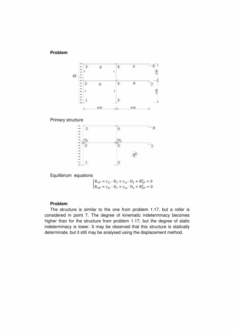
Problem
The structure is similar to the one from problem 1.17, but a roller is
considered in point 7. The degree of kinematic indeterminacy becomes
higher than for the structure from problem 1.17, but the degree of static
indeterminacy is lower. It may be observed that this structure is statically
determinate, but it still may be analysed using the displacement method.

Primary structure
0
Equilibrium equations
HR�� = r�� ∙ D� + r�; ∙ D; + r�O ∙ DO + R��� = 0R;� = r;� ∙ D� + r;; ∙ D; + r;O ∙ DO + R;�� = 0RO� = rO� ∙ D� + rO; ∙ D; + rOO ∙ DO + RO�� = 0

Problem
The geometry of the two structures bellow is similar, excepting for the
bending rigidity of column 1-2.
Primary structure (the same for both structures)
0
Problem
Primary structure
0

Equilibrium equations >R�� = r�� ∙ D� + r�; ∙ D; + R��� = 0R;� = r;� ∙ D� + r;; ∙ D; + R;�� = 0
3. STATICALLY INDETERMINATE STRUCTURES
SUBJECTED TO TEMPERATURE VARIATION
2.1 Flexibility Method
Problem
The structure is the same as the one from problem 1.3
CI = 0.448 ∙ 10) def; ℎ�O = 40 hf ℎO@ = 50 hf ℎ@) = 40 hf i = 10j) tan i = 54 i = 51.34° sin i = 0.781 cos i = 0.625
The degree of static indeterminacy of structure is 1, while the degree of
kinematic indeterminacy is 2. Therefore, for this problem it is easier to use
the flexibility method (1 unknown) instead of the displacement method (2
unknowns- one rotation and one linear displacement)
Primary structure
0
Compatibility equation D�A = d�� ∙ X� + D�A� = 0 ��� – rotation at the point and in the direction of the redundant moment
reaction X1, caused by the unit value of X1, acting on the primary structure ��<� – rotation at the point and in the direction of the redundant moment
reaction X1, caused by the temperature variation on the primary structure;

��A – rotation at the point and in the direction of the redundant moment
reaction X1, caused by X1 and by temperature variation on the primary
structure; it must be zero, because in this point and on the direction of X1, on
the real structure exists a link which does not allow this displacement (fixed
support)
Temperature diagrams
m
Bending moment and axial force due to unit rotation X1=1
1
1
n)@ = R()� ∙ sin α − R")� ∙ cos α = 0.111 ∙ 0.781 − 0.111 ∙ 0.625 = 0.01732 n�O = −R(�� = −0.111 nO@ = −R"�� = −0.111
The value for ��� is the same as for the structure from Problem 1.3 d�� = 2.904EI

D�A� = � M n� ∙ α ∙ t^ d x + M m� ∙ α ∙ ∆th dx= α ∙ 2−0.111 ∙ 5 ∙ 10 − 0.111 ∙ 5 ∙ 5 + 0.01732 ∙ 6.403 ∙ 53 + +α ∙ 5200.4 ∙ 12 ∙ 2−0.5553 ∙ 5 + 300.5 ∙ 12 ∙ 2−0.5553 ∙ 5 + 300.4 ∙ 12 ∙ 1 ∙ 6.4036 = α ∙ 2−7.771 + 87.493 = 79.72 ∙ α 2.904EI ∙ X� + 79.72 ∙ α = 0 X� = −27.4518 ∙ EI ∙ α = −12.30kNm
Displacement Method
Problem
The structure is the same as the one from problem 1.15
CI = 1.134 ∙ 10) def; ℎ�; = 50 hf ℎO@ = 40 hf ℎ;O = ℎO) = 60 hf i = 10j)
The degree of static indeterminacy of the structure is 3, while the degree
of kinematic indeterminacy is 2. Therefore, for this problem, it is easier to
use the displacement method (2 unknowns – one rotation and one linear
displacement) instead of the flexibility method (3 unknowns).
Primary structure
0
Equilibrium equations >R�A = r�� ∙ D� + r�; ∙ D; + R�A� = 0R;A = r;� ∙ D� + r;; ∙ D; + R;A� = 0 �� – moment reaction in the rotational restraint 1, caused by the unit
rotation of D1 imposed on the primary structure; ;; – force reaction in the linear displacement restraint 2, caused by the
unit displacement of D2 imposed on the primary structure; �; – moment reaction in the rotational restraint 1, caused by the unit
displacement of D2 imposed on the primary structure;

;� – force reaction in the linear displacement restraint 2, caused by the
unit rotation of D1 imposed on the primary structure; R�<� – moment reaction in the rotational restraint 1, caused by the
temperature variation on the primary structure; R;<� – force reaction in the linear displacement restraint 2 caused by the
temperature variation on the primary structure; b�A – moment reaction in the rotational restraint 1, caused by the rotation
D1, linear displacement D2 and the temperature variation on the primary
structure; b;A – force reaction in the linear displacement restraint 2, caused by the
rotation D1, linear displacement D2 and the temperature variation on the
primary structure.
Fixed end moments on the primary structure due to uv
w∆l�; = α ∙ t^�; ∙ l�; = α ∙ 25 ∙ 4 = 100 ∙ α∆l;O = α ∙ t^;@ ∙ l;@ = α ∙ 25 ∙ 5 = 125 ∙ α∆lO@ = α ∙ t^O@ ∙ lO@ = α ∙ 15 ∙ 4 = 60 ∙ α∆lO) = α ∙ t^@) ∙ l@) = α ∙ 25 ∙ 4 = 100 ∙ α M�;A^ = 3 ∙ E ∙ 2I2l�;3; ∙ 2∆l;O + ∆lO)3 = 95.68 kNm
MO;A^ = 3 ∙ E ∙ 3I2l;O3; ∙ 2∆l�; − ∆lO@3 = 16.33 kNm M@OA^ = MO@A^ = 6 ∙ EI2lO@3; ∙ ∆lO) = 42.53 kNm MO)A^ = 3 ∙ E ∙ 3I2lO)3; ∙ ∆lO@ = 38.27 kNm
Fixed end moments on the primary structure due to ∆u M�;∆A = 32 ∙ α ∙ ∆th�; ∙ E ∙ 2I = 32 ∙ 10j) ∙ 200.5 ∙ 2 ∙ 1.134 ∙ 10) = 136.08

MO;∆A = 32 ∙ α ∙ ∆th;@ ∙ E ∙ 3I = 32 ∙ 10j) ∙ 200.6 ∙ 3 ∙ 1.134 ∙ 10) = 170.1 MO)∆A = 32 ∙ α ∙ ∆th@) ∙ E ∙ 3I = 32 ∙ 10j) ∙ 200.6 ∙ 3 ∙ 1.134 ∙ 10) = 170.1 MO@∆A = M@O∆A = α ∙ ∆th ∙ E ∙ I = 10j) ∙ 100.4 ∙ 1.134 ∙ 10) = 28.35
Moment reaction in the restrained joint
R�AA^ + 38.27 − 42.53 + 16.33 = 0 ⟹ R�AA^ = −12.07 R�A∆A + 170.1 + 28.35 − 170.1 = 0 ⟹ R�A∆A = −28.35
R�A� = R�AA^ + R�A∆^ = −40.42 kNm
Force reaction in the restrained joint
�� M � = 0 − R(;�A^ ∙ 4 + 95.68 = 0 R(;�A^ = 23.92kN �� M O = 0 − R(@OA^ ∙ 4 + 42.53 ∙ 2 = 0 R(@OA^ = 21.27kN R;A^ + 23.92 + 21.27 = 0 R;A^ = −45.19 kN

�� x � = 0 by;�∆< ∙ 4 − 136.02 = 0 by;�∆< = 34.02kN �� x O = 0 − by;�∆< ∙ 4 + 28.35 − 28.35 = 0 by;�∆< = 0 R;∆A − 34.02 = 0 R;∆A = 34.02 R;A� = R;A^ + R;∆A = −11.17kN
The fixed end moments due to unit rotation D1=1 and unit linear
displacement D2=1 are the same as for the structure from problem 1.16
r�� = 5.05 ∙ EI r�; = −0.375 ∙ EI = r;� r;; = 0.2814 ∙ EI a 5.05 ∙ D� + 2−0.3753 ∙ D; + 2−40.423 = 0−0.375 ∙ D� + 0.2814 ∙ D; + 2−11.173 = 0 D� = 12.154EI D; = 55.892EI

4. STATICALLY INDETERMINATE STRUCTURES
SUBJECTED TO SUPPORT SETTLEMENTS
Flexibility Method
Problem
The structure is the same as the one from problem 1.3 and 2.1
CI = 4.48 ∙ 10@ def; tan i = 54 i = 51.34° sin i = 0.781 cos i = 0.625
Primary structure
0
Compatibility equation D�z = d�� ∙ X� + D�z� = +φ) ��� – rotation at the point and in the direction of the redundant moment
reaction X1, caused by the unit value of X1, acting on the primary structure; ��|� – rotation at the point and in the direction of the redundant moment
reaction X1, caused by the displacements of the supports on the primary
structure; ��z – rotation at the point and in the direction of the redundant moment
reaction X1, caused by X1 and by the displacements of the supports on the
primary structure; this must be identical to the rotation of the support on the
real structure (f5).

1
d�� = 2.904EI D�z� = −QR(�� ∙ 2−v�3 + 2−R()� 3 ∙ 2−v)3 + 2−R")� 3 ∙ u)R= 0.111 ∙ 2−0.013 + 0.111 ∙ 20.023 + 2−0.1113 ∙ 20.0153= 0.000555 φ) = 1.2° = 1.2 ∙ π180 rad = 0.020944 D�z = 2.904EI X� + 0.000555 = 0.020944 X� = 70.21 ∙ 10j@EI = 314.54 kNm
3.2 Displacement Method
Problem
The structure is the same as the one from problem 1.15 and 2.2.
CI = 1.134 ∙ 10) def;
Primary structure

0
Equilibrium equations >R�z = r�� ∙ D� + r�; ∙ D; + R�z� = 0R;z = r;� ∙ D� + r;; ∙ D; + R;z� = 0 �� – moment reaction in the rotational restraint 1, caused by the unit
rotation of D1 imposed on the primary structure; ;; – force reaction in the linear displacement restraint 2, caused by the
unit displacement of D2 imposed on the primary structure; �; – moment reaction in the rotational restraint 1, caused by the unit
displacement of D2 imposed on the primary structure; ;� – force reaction in the linear displacement restraint 2, caused by the
unit rotation of D1 imposed on the primary structure; b�|� – moment reaction in the rotational restraint 1, caused by the
displacement of the support on the primary structure; b;|� – force reaction in the linear displacement restraint 2, caused by the
displacement of the support on the primary structure; b�z – moment reaction in the rotational restraint 1, caused by the rotation
D1, linear displacement D2 and the displacement of the support on the
primary structure; b;z – force reaction in the linear displacement restraint 2, caused by the
rotation D1, linear displacement D2 and the displacement of the support on
the primary structure.
Fixed end moments caused by support displacement
φ;O�� = 0.0065 MO;�� = 3 ∙ E ∙ 3I5 ∙ 0.0065 = 0.00216 ∙ EI

φ;O�@ = 0.0045 MO;�O = 3 ∙ E ∙ 3I5 ∙ 0.0045 = 0.00144 ∙ EI φO)�@ = 0.0044 MO)�O = 3 ∙ E ∙ 3I4 ∙ 0.0044 = 0.00225 ∙ EI
φO@�@ = 0.0054 M@O�O = MO@�O = 6 ∙ EI4 ∙ 0.0054 = 0.001875 ∙ EI
φ@ = 0.8° = 0.8 ∙ π180 MO@�� = 4 ∙ EI4 ∙ 0.8 ∙ π180 = 13.96 ∙ 10jO ∙ EI M@O�� = 2 ∙ EI4 ∙ 0.8 ∙ π180 = 6.98 ∙ 10jO ∙ EI
φO)�) = 0.014 M@)�) = 3 ∙ E ∙ 3I4 ∙ 0.014 = 5.625 ∙ 10jO ∙ EI
Final diagram for fixed end moments caused by support displacements

0s
Moment reaction in the restrained joint
R�z� + 3.375 ∙ 10jO ∙ EI + 5.105 ∙ 10jO ∙ EI − 0.72 ∙ 10jO ∙ EI = 0 R�z� = −7.76 ∙ 10jO ∙ EI = 880kNm
Force reaction in the restrained joint
�� M O = 0 R(O@z ∙ 4 + 2−5.105 − 12.0853 ∙ 10jO ∙ EI = 0 R(O@z = 17.194 ∙ 10jO ∙ EI = 4.2975 ∙ 10jO ∙ EI
R;z� − R(O@z = 0 R;z = R(O@z = 4.2975 ∙ 10jO ∙ EI
The fixed end moments due to unit displacement D1 and unit linear
displacement D2 are the same as for the structure from problem 1.15. r�� = 5.05EI r�; = −0.375EI r;; = 0.2814EI a 5.05EI ∙ D� − 0.375EI ∙ D; − 7.76 ∙ 10jO ∙ EI = 0−0.375EI ∙ D� + 0.2813EI ∙ D; + 4.275 ∙ 10jO ∙ EI = 0 D� = 0.4462 ∙ 10jO D; = −14.683 ∙ 10jO


