
S TRUC T UR A L PR E - A N A LYS I S TA B LE S
M A D E F O R B U I L D I N GB U I L T F O R L I V I N G

I M P R I N T
© KLH Massivholz GmbH
Publisher and responsible for the content: KLH Massivholz GmbHVersion: Structural pre-analysis tables, September 2017
The content of this brochure is intellectual property of the company and is protected by copyright. The statements are recommendations and proposals only; a liability on the part of the publisher is excluded. Any type of reproduction is strictly forbidden and only permitted after written approval of the publisher.
01 STANDARD PANELS AND PANEL STRUCTURES 03
02 KLH AS A V IS IBLE WALL 04
03 KLH AS A CL ADDED WALL 08
04 KLH AS A CEIL ING - S INGLE-SPAN BE AM 12
05 KLH AS A CEIL ING - DOUBLE-SPAN BE AM 18
06 KLH AS A ROOF - S INGLE-SPAN BE AM 24
07 KLH AS A ROOF - DOUBLE-SPAN BE AM 26
C O N T E N T
0 1

The calculation model for KLH solid wood panels must
consider the influence of the layup (thickness, material,
orientation), the internal stress distributions and local
stress concentrations. Due to the shear flexible transverse
layers, shear deformation may no longer be disregarded
and the layup of the panel has to be taken into account.
Dimensioning and structural design follow Eurocode 5
(EN 1995-1-1 and EN 1995-1-2), taking into account the
national standards set forth in ÖNORM B 1995-1-1 and
ÖNORM B 1995-1-2. It should be pointed out that the
national standards in various European countries differ
from each other in some detailed aspects (e.g. different
partial factors γM for “cross laminated timber” material).
The material properties of KLH solid wood panels
required for structural design can be taken from the
European Technical Assessment (ETA-06/0138).
The structural design of KLH solid wood panels has
to be carried out project-based and locally applicable
standards and regulations have to be taken into account.
Due care is also advised when comparing panel
thicknesses of KLH elements with products from other
manufacturers: due to different production processes, the
cross laminated timber products may well have different
properties, e.g. with respect to bending stiffness or shear
strength. Please mind the relevant properties in the
respective product approvals and take into account the
differences in a comparative analysis.
For the structural analysis of cross laminated timber,
different models have been developed in the past. The
structural analysis of KLH solid wood panels is based on
the shear-elastic beam theory (according to Timoshenko)
or the shear-elastic orthotropic plate (according to
Reissner-Mindlin). The properties of the composite cross
section are thereby described appropriately. To receive
correct results (internal forces and moments as well
as deformations) is the use of suitable software for the
purpose of structural analysis. The software provided on
the website by KLH Massivholz GmbH is based on the
above mentioned theory and thus a good choice.
I N T R O D U C T I O N
0 2
STRUCTURALPRE-ANALYSISTABLES

0 3
S T A N D A R D P A N E L S A N D P A N E L S T R U C T U R E S
01 KLH-STANDARD PANEL TYPES AND STRUCTURES
Nominal thickness Layers|Type Lamella structure in [mm]
T L T L T L T
KLH 60 mm 3s TT 20 20 20
KLH 70 mm 3s TT 25 20 25
KLH 80 mm 3s TT 30 20 30
KLH 90 mm 3s TT 30 30 30
KLH 100 mm 3s TT 30 40 30
KLH 110 mm 3s TT 35 40 35
KLH 120 mm 3s TT 40 40 40
KLH 100 mm 5s TT 20 20 20 20 20
KLH 110 mm 5s TT 25 20 20 20 25
KLH 120 mm 5s TT 30 20 20 20 30
KLH 130 mm 5s TT 30 20 30 20 30
KLH 140 mm 5s TT 30 30 20 30 30
KLH 150 mm 5s TT 30 35 20 35 30
KLH 160 mm 5s TT 30 35 30 35 30
KLH 180 mm 7s TT 30 20 30 20 30 2 0 3 0
max. 2.95 m
panel length m
ax. 16.50 m
3s TT 5s TT 7s TT
L T L T L T L
KLH 60 mm 3s T L 20 20 20
KLH 70 mm 3s T L 20 30 20
KLH 80 mm 3s T L 30 20 30
KLH 90 mm 3s T L 35 20 35
KLH 100 mm 3s T L 35 30 35
KLH 110 mm 3s T L 35 40 35
KLH 120 mm 3s T L 40 40 40
KLH 100 mm 5s T L 20 20 20 20 20
KLH 110 mm 5s T L 20 25 20 25 20
KLH 120 mm 5s T L 20 30 20 30 20
KLH 130 mm 5s T L 35 20 20 20 35
KLH 140 mm 5s T L 40 20 20 20 40
KLH 150 mm 5s T L 40 20 30 20 40
KLH 160 mm 5s T L 40 20 40 20 40
KLH 170 mm 5s T L 40 25 40 25 40
KLH 180 mm 5s T L 40 30 40 30 40
KLH 190 mm 5s T L 40 35 40 35 40
KLH 200 mm 5s T L 40 40 40 40 40
KLH 160 mm 5ss T L 30+30 40 30+30
KLH 200 mm 7s T L 20 40 20 40 20 40 20
KLH 220 mm 7s T L 30 35 30 30 30 35 30
KLH 240 mm 7s T L 30 40 30 40 30 40 30
KLH 200 mm 7ss T L 30+30 25 30 25 30+30
KLH 210 mm 7ss T L 30+30 30 30 30 30+30
KLH 220 mm 7ss T L 40+40 20 20 20 40+40
KLH 230 mm 7ss T L 35+40 20 40 20 40+35
KLH 240 mm 7ss T L 40+40 20 40 20 40+40
KLH 250 mm 7ss T L 35+40 30 40 30 40+35
KLH 260 mm 7ss T L 40+40 30 40 30 40+40
KLH 280 mm 7ss T L 40+40 40 40 40 40+40
KLH 300 mm 8ss T L 40+40 30 40+40 30 40+40
KLH 320 mm 8ss T L 40+40 40 40+40 40 40+40
max. 2.95 m
panel length m
ax. 16.50 m
3s TL 5s TL 7s TL
7ss TL 8ss TL5ss TL
Special panel layups are avai lable on reques t . By using double layers, for example the long i tudinal or t ransverse s t i f fness of the panel can be fur ther en -hanced. The f i re res is tance of the KLH sol id wood panel can also be inf luenced by modi f y ing the s t ruc tures and can eventual ly be improved in re lat ion to
speci f ic projec t requirements.
C h a r g i n g w i d t h s 2.40 | 2.50 | 2.73 | 2.95 [m]
M a x i m u m l e n g t h 16.50 [m]
M a x i m u m t h i c k n e s s 0.5 [m]
FO
R T
HE
WA
LL
Cov
erin
g la
yer
in the
tra
nsve
rse
pan
el d
irec
tion
TT
FO
R C
EIL
ING
AN
D R
OO
F
Cov
erin
g la
yer
in the
long
itud
inal
pan
el d
irec
tion
TL

S T R U C T U R A L P R E - A N A LY S I S T A B L E S
0 4
2.1 SINGLE-SIDED FIRE EXPOSURE (FOR EXTERIOR WALLS)
according to ETA-06/0138
ÖNORM EN 1995-1-1:2015 and ÖNORM B 1995-1-1:2015
ÖNORM EN 1995-1-2:2011 and ÖNORM B 1995-1-2:2011
Wind pressure: wk = 0,8 kN/m2
Minimum panel thickness for various fire resistance classes (R 0 to R 90)
nk
wk
gk
ℓ
02 KLH AS A VISIBLE WALL
Permanent load
Imposed load
HEIGHT WALL (buckling length ℓ)
g2,k
nk
2,73 m 2,95 m
[kN/m] [kN/m] R 0 R 30 R 60 R 90 R 0 R 30 R 60 R 90
10,00
10,00
3s 60 TT 3s 80 TT 5s 100 TT 5s 120 TT 3s 60 TT 3s 80 TT 5s 100 TT 5s 120 TT
20,0030,0040,0050,0060,00
20,00
10,00
3s 60 TT 3s 80 TT 5s 100 TT 5s 120 TT 3s 60 TT 3s 80 TT 5s 100 TT 5s 120 TT
20,0030,0040,0050,0060,00
30,00
10,00
3s 60 TT3s 80 TT 5s 100 TT 5s 120 TT
3s 60 TT3s 80 TT 5s 100 TT
5s 120 TT20,0030,0040,0050,00
3s 70 TT60,00 3s 70 TT 5s 130 TT
40,00
10,00
3s 60 TT3s 80 TT 5s 100 TT
5s 120 TT3s 60 TT
3s 80 TT 5s 100 TT
5s 120 TT20,0030,00
5s 130 TT40,00
3s 70 TT50,003s 70 TT
60,00 5s 130 TT
50,00
10,003s 60 TT
3s 80 TT 5s 100 TT
5s 120 TT3s 60 TT
3s 80 TT 5s 100 TT 5s 130 TT
20,0030,00
3s 70 TT40,00
3s 70 TT 5s 130 TT50,0060,00
60,00
10,003s 60 TT
3s 80 TT 5s 100 TT 5s 130 TT3s 70 TT
3s 80 TT 5s 100 TT 5s 130 TT
20,0030,00
3s 70 TT40,0050,0060,00 3s 80 TT
R 0 R 30 R 60 R 90
Service class 1
Imposed load category A (ψ0 = 0,7 and ψ2 = 0,3): kmod = 0,8
Wind loads (ψ0 = 0,6 and ψ2 = 0,0): kmod = 1,0
Self-weight of KLH is already taken into account in the table.
Load-bearing capacity
a) verification of column stability (compression and deflection according to equivalent member method)
b) verification of shear resistance
Structural fire design (single -sided fire exposure)
Application of KLHdesigner based on the „reduced properties method“ according to ETA-06/0138.
a) charring rate β1 = 0,55 mm/min regular charring rate (charring within one single layer)
b) charring rate β2= 0,80 mm/min increased charring rate (after the failure / falling off of one layer)
c) for local panel parts b < 300 mm higher charring rates are mandatory
d) additional eccentricity due to burn-off taken into account
This table is only intended for structural pre-analysis purposes and does not replace necessary static calculations!
S T R U C T U R A L P R E - A N A LY S I S T A B L E S
0 5

S T R U C T U R A L P R E - A N A LY S I S T A B L E S
2.2 DOUBLE-SIDED FIRE EXPOSURE (FOR INTERIOR WALLS)
according to ETA-06/0138
ÖNORM EN 1995-1-1:2015 and ÖNORM B 1995-1-1:2015
ÖNORM EN 1995-1-2:2011 and ÖNORM B 1995-1-2:2011
Minimum panel thickness for various fire resistance classes (R 0 to R 60)
nk
gk
ℓ
0 6
Permanent load
Imposed load
HEIGHT WALL (buckling length ℓ)
g2,k
nk
2,73 m 2,95 m
[kN/m] [kN/m] R 0 R 30 R 60 R 0 R 30 R 60
10,00
10,00
3s 60 TT 3s 80 TT 7s 180 TT 3s 60 TT3s 80 TT
7s 180 TT
20,0030,0040,0050,00
3s 90 TT60,00
20,00
10,00
3s 60 TT
3s 80 TT
7s 180 TT 3s 60 TT
3s 80 TT
7s 180 TT
20,00
3s 90 TT30,00
3s 90 TT40,0050,0060,00
30,00
10,00
3s 60 TT3s 90 TT
7s 180 TT3s 60 TT
3s 90 TT7s 180 TT
20,0030,0040,0050,00
3s 100 TT 3s 100 TT60,00 3s 70 TT
40,00
10,00
3s 60 TT
3s 90 TT
7s 180 TT3s 60 TT
3s 90 TT
7s 180 TT
20,00
3s 100 TT30,00
3s 100 TT40,0050,0060,00 3s 70 TT 3s 70 TT
50,00
10,00
3s 60 TT3s 100 TT 7s 180 TT
3s 60 TT
3s 100 TT 7s 180 TT
20,0030,0040,00
3s 70 TT50,003s 70 TT
60,00
60,00
10,003s 60 TT
3s 100 TT 7s 180 TT
3s 60 TT 3s 100 TT
7s 180 TT
20,0030,00
3s 70 TT 3s 110 TT40,00
3s 70 TT50,0060,00
R 0 R 30 R 60

Service class 1
Imposed load category A (ψ0 = 0,7 and ψ2 = 0,3): kmod = 0,8
Self-weight of KLH is already taken into account in the table.
Load-bearing capacity
a) verification of column stability (compression and deflection according to equivalent member method)
Structural fire design (double-sided fire exposure)
Application of KLHdesigner based on the „reduced properties method“ according to ETA-06/0138.
a) charring rate β1 = 0,55 mm/min regular charring rate (charring within one single layer)
b) charring rate β2 = 0,80 mm/min increased charring rate (after the failure / falling off of one layer)
c) for local panel parts b < 300 mm higher charring rates are mandatory
This table is only intended for structural pre-analysis purposes and does not replace necessary static calculations!
0 7
S T R U C T U R A L P R E - A N A LY S I S T A B L E S

S T R U C T U R A L P R E - A N A LY S I S T A B L E S
0 8
03 KLH AS A CLADDED WALL
3.1 SINGLE-SIDED FIRE EXPOSURE (FOR EXTERIOR WALLS)
according to ETA-06/0138
ÖNORM EN 1995-1-1:2015 and ÖNORM B 1995-1-1:2015
ÖNORM EN 1995-1-2:2011 and ÖNORM B 1995-1-2:2011
Wind pressure: wk = 0,8 kN/m2
Minimum panel thickness for various fire resistance classes (R 30 to R 120)
with 15 mm fire rated gypsum plasterboard type F (GtF) on the fire exposed side
nk
wk
gk
ℓ
Permanent load
Imposed load
HEIGHT WALL (buckling length ℓ)
g2,k
nk
2,73 m 2,95 m
[kN/m] [kN/m] R 30 R 60 R 90 R 120 R 30 R 60 R 90 R 120
10,00
10,00
3s 80 TT 3s 80 TT 3s 120 TT 5s 110 TT 3s 80 TT 3s 80 TT 3s 120 TT 5s 110 TT
20,0030,0040,0050,0060,00
20,00
10,00
3s 80 TT 3s 80 TT 3s 120 TT5s 110 TT
3s 80 TT 3s 80 TT 3s 120 TT5s 110 TT
20,0030,0040,0050,00
5s 120 TT60,00 5s 120 TT
30,00
10,00
3s 80 TT 3s 80 TT 3s 120 TT5s 110 TT
3s 80 TT 3s 80 TT 3s 120 TT
5s 110 TT20,0030,00
5s 120 TT40,0050,00
5s 120 TT60,00
40,00
10,00
3s 80 TT 3s 80 TT 3s 120 TT 5s 120 TT 3s 80 TT 3s 80 TT 3s 120 TT 5s 120 TT
20,0030,0040,0050,0060,00
50,00
10,00
3s 80 TT 3s 80 TT 3s 120 TT 5s 120 TT 3s 80 TT 3s 80 TT 3s 120 TT 5s 120 TT
20,0030,0040,0050,0060,00
60,00
10,00
3s 80 TT 3s 80 TT 3s 120 TT 5s 120 TT 3s 80 TT 3s 80 TT 3s 120 TT 5s 120 TT
20,0030,0040,0050,0060,00
R 30 R 60 R 90 R 120
Service class 1
Imposed load category A (ψ0 = 0,7 and ψ2 = 0,3): kmod = 0,8
Wind loads (ψ0 = 0,6 and ψ2 = 0,0): kmod = 1,0
Self-weight of KLH is already taken into account in the table.
Load-bearing capacity
a) verification of column stability (compression and deflection according to equivalent member method)
b) verification of shear resistance
Structural fire design (single -sided fire exposure)
Application of KLHdesigner based on the „reduced properties method“ according to ETA-06/0138.
a) charring rate β1 = 0,55 mm/min regular charring rate (charring within one single layer)
b) charring rate β2 = 0,80 mm/min increased charring rate (after the failure / falling off of one layer)
c) for local panel parts b < 300 mm higher charring rates are mandatory
d) additional eccentricity due to burn-off taken into account
Cladding
For the cladding directly to the KLH surface, srew-fastened fire rated gypsum plasterboards type F (GtF according to
ÖNORM EN 520 and ÖNORM B 3410 or DIN 18180) or equivalent panels are required. The fastening needs to comply
with the state of the art and the current KLH installation guidelines.
This table is only intended for structural pre-analysis purposes and does not replace necessary static calculations!
S T R U C T U R A L P R E - A N A LY S I S T A B L E S
0 9

S T R U C T U R A L P R E - A N A LY S I S T A B L E S
1 0
3.2 DOUBLE-SIDED FIRE EXPOSURE (FOR INTERIOR WALLS)
according to ETA-06/0138
ÖNORM EN 1995-1-1:2015 and ÖNORM B 1995-1-1:2015
ÖNORM EN 1995-1-2:2011 and ÖNORM B 1995-1-2:2011
Minimum panel thickness for various fire resistance classes (R 30 to R 120)
with 15 mm fire rated gypsum plasterboard type F (GtF) on both sides
Permanent load
Imposed load
HEIGHT WALL (buckling length ℓ)
g2,k
nk
2,73 m 2,95 m
[kN/m] [kN/m] R 30 R 60 R 90 R 120 R 30 R 60 R 90 R 120
10,00
10,00
3s 80 TT* 3s 80 TT* 3s 120 TT* 3s 100 TT** 3s 80 TT* 3s 80 TT* 3s 120 TT* 3s 100 TT**
20,0030,0040,0050,0060,00
20,00
10,00
3s 80 TT* 3s 80 TT* 3s 120 TT* 3s 100 TT** 3s 80 TT* 3s 80 TT* 3s 120 TT* 3s 100 TT**
20,0030,0040,0050,0060,00
30,00
10,00
3s 80 TT* 3s 80 TT* 3s 120 TT* 3s 100 TT** 3s 80 TT* 3s 80 TT* 3s 120 TT* 3s 100 TT**
20,0030,0040,0050,0060,00
40,00
10,00
3s 80 TT* 3s 80 TT* 3s 120 TT* 3s 100 TT** 3s 80 TT* 3s 80 TT*3s 120 TT*
3s 100 TT**
20,0030,0040,0050,0060,00 3s 80 TT**
50,00
10,00
3s 80 TT* 3s 80 TT*3s 120 TT*
3s 100 TT** 3s 80 TT*
3s 80 TT*3s 120 TT*
3s 100 TT**
20,0030,00
3s 80 TT**40,00
3s 90 TT*50,0060,00 3s 80 TT**
60,00
10,00
3s 80 TT*
3s 80 TT*3s 120 TT*
3s 100 TT** 3s 80 TT* 3s 90 TT* 3s 80 TT** 3s 100 TT**
20,00
3s 80 TT**30,0040,00
3s 90 TT*50,0060,00
nk
gk
ℓ
* with 1 x 15 mm GtF on both sides R 30 R 60 R 90
** with 2 x 15 mm GtF on both sides R 90 R 120

Service class 1
Imposed load category A (ψ0 = 0,7 and ψ2 = 0,3): kmod = 0,8
Self-weight of KLH is already taken into account in the table.
Load-bearing capacity
a) verification of column stability (compression and deflection according to equivalent member method)
Structural fire design (double-sided fire exposure)
Application of KLHdesigner based on the „reduced properties method“ according to ETA-06/0138.
a) charring rate β1 = 0,55 mm/min regular charring rate (charring within one single layer)
b) charring rate β2 = 0,80 mm/min increased charring rate (after the failure / falling off of one layer)
c) for local panel parts b < 300 mm higher charring rates are mandatory
Cladding
For the cladding directly to the KLH surface, srew-fastened fire rated gypsum plasterboards type F (GtF according to
ÖNORM EN 520 and ÖNORM B 3410 or DIN 18180) or equivalent panels are required. The fastening needs to comply
with the state of the art and the current KLH installation guidelines.
This table is only intended for structural pre-analysis purposes and does not replace necessary static calculations!
S T R U C T U R A L P R E - A N A LY S I S T A B L E S
1 1
S T R U C T U R A L P R E - A N A LY S I S T A B L E S
1 2
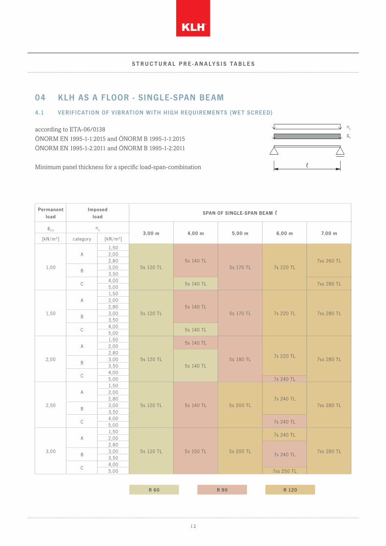
4.1 VERIFICATION OF VIBRATION WITH HIGH REQUIREMENTS (WET SCREED)
according to ETA-06/0138
ÖNORM EN 1995-1-1:2015 and ÖNORM B 1995-1-1:2015
ÖNORM EN 1995-1-2:2011 and ÖNORM B 1995-1-2:2011
Minimum panel thickness for a specific load-span-combination
nk
gk
ℓ
04 KLH AS A FLOOR - SINGLE-SPAN BEAM
R 60 R 90 R 120
Permanent load
Imposed load
SPAN OF SINGLE-SPAN BEAM ℓ
g2,k
nk
3,00 m 4,00 m 5,00 m 6,00 m 7,00 m[kN/m²] category [kN/m²]
1,00
A1,50
5s 120 TL5s 140 TL
5s 170 TL 7s 220 TL7ss 260 TL
2,002,80
B3,003,50
C4,00
5s 140 TL 7ss 280 TL5,00
1,50
A1,50
5s 120 TL5s 140 TL
5s 170 TL 7s 220 TL 7ss 280 TL
2,002,80
B3,003,50
C4,00
5s 140 TL5,00
2,00
A1,50
5s 120 TL
5s 140 TL
5s 180 TL7s 220 TL
7ss 280 TL
2,002,80
5s 140 TLB
3,003,50
C4,005,00 7s 240 TL
2,50
A1,50
5s 120 TL 5s 140 TL 5s 200 TL7s 240 TL
7ss 280 TL
2,002,80
B3,003,50
C4,00
7s 240 TL5,00
3,00
A1,50
5s 120 TL 5s 150 TL 5s 200 TL
7s 240 TL
7ss 280 TL
2,002,80
7s 240 TLB3,003,50
C4,005,00 7ss 250 TL

S T R U C T U R A L P R E - A N A LY S I S T A B L E S
1 3
Service class 1
kdef = 0,6
Imposed load category A and B (ψ0 = 0,7 and ψ2 = 0,3): kmod = 0,8
Imposed load category C (ψ0 = 0,7 and ψ2 = 0,6): kmod = 0,9
Self-weight of KLH is already taken into account in the table.
Deflection limits according to ÖNORM EN 1995-1-1:2015
a) characteristic design situation: wQ,inst ≤ ℓ/300 and (wfin – wG,inst) ≤ ℓ/200
b) quasi-permanent structural design situation: wfin ≤ ℓ/250
Vibration verification according to ÖNORM B 1995-1-1:2015
a) floor slab class I: slab between different utilisation units (e.g. separating floor slabs for apartments or offices);
6 cm wet screed, floating on filler
b) limiting value of the frequency and stiffness criterion: f1,min ≥ 4,5 Hz; f1 ≥ fgr = 8 Hz; wstat ≤ wgr = 0,25 mm
c) modal damping ratio for cross-laminated timber floor slabs with floating screed and heavy floor structure: ζ = 4,0 %
d) limiting value acceleration (required at f1,min ≤ f1 ≤ fgr): arms ≤ agr = 0,05 m/s²
e) floor slab width (b) ≤ 1,2 * span (1,2*l)
Load-bearing capacity
a) verification of bending resistance
b) verification of shear resistance
Structural fire design (single -sided fire exposure)
Application of KLHdesigner based on the „reduces properties method“ according to ETA-06/0138.
a) charring rate β1 = 0,65 mm/min regular charring rate (charring within one single layer)
b) charring rate β2 = 1,00 mm/min increased charring rate (after the failure / falling off of one layer)
c) for local panel parts b < 300 mm higher charring rates are mandatory
d) the minimum panel thicknesses (for R 0) automatically reach fire resistance according to coloured marking
This table is only intended for structural pre-analysis purposes and does not replace necessary static calculations!

S T R U C T U R A L P R E - A N A LY S I S T A B L E S
1 4
4.2 VERIFICATION OF VIBRATION WITH HIGH REQUIREMENTS (DRY SCREED)
according to ETA-06/0138
ÖNORM EN 1995-1-1:2015 and ÖNORM B 1995-1-1:2015
ÖNORM EN 1995-1-2:2011 and ÖNORM B 1995-1-2:2011
Minimum panel thickness for a specific load-span-combination
nk
gk
ℓ
R 60 R 90 R 120
Permanent load
Imposed load
SPAN OF SINGLE-SPAN BEAM ℓ
g2,k
nk
3,00 m 4,00 m 5,00 m 6,00 m 7,00 m[kN/m²] category [kN/m²]
1,00
A1,50
5s 130 TL 5s 150 TL 5s 170 TL 7s 220 TL 7ss 280 TL
2,002,80
B3,003,50
C4,005,00
1,50
A1,50
5s 130 TL 5s 150 TL 5s 170 TL 7s 220 TL 7ss 280 TL
2,002,80
B3,003,50
C4,005,00
2,00
A1,50
5s 130 TL 5s 150 TL 5s 190 TL7s 240 TL
7ss 280 TL
2,002,80
B3,003,50
C4,00
7s 240 TL5,00
2,50
A1,50
5s 130 TL 5s 150 TL 5s 200 TL7s 240 TL
7ss 280 TL
2,002,80
B3,003,50
C4,00
7s 240 TL5,00
3,00
A1,50
5s 130 TL 5s 150 TL 5s 200 TL
7s 240 TL
7ss 280 TL
2,002,80
7s 240 TLB3,003,50
C4,005,00 7ss 250 TL

S T R U C T U R A L P R E - A N A LY S I S T A B L E S
1 5
Service class 1
kdef = 0,6
Imposed load category A and B (ψ0 = 0,7 and ψ2 = 0,3): kmod = 0,8
Imposed load category C (ψ0 = 0,7 and ψ2 = 0,6): kmod = 0,9
Self-weight of KLH is already taken into account in the table.
Deflection limits according to ÖNORM EN 1995-1-1:2015
a) characteristic design situation: wQ,inst ≤ ℓ/300 and (wfin – wG,inst) ≤ ℓ/200
b) quasi-permanent structural design situation: wfin ≤ ℓ/250
Vibration verification according to ÖNORM B 1995-1-1:2015
a) floor slab class I: slab between different utilisation units (e.g. separating floor slabs for apartments or offices);
dry screed, floating on heavy filler (at least 60 kg/m²)
b) limiting value of the frequency and stiffness criterion: f1,min ≥ 4,5 Hz; f1 ≥ fgr = 8 Hz; wstat ≤ wgr = 0,25 mm
c) modal damping ratio for cross-laminated timber floor slabs with floating screed and heavy floor structure: ζ = 4,0 %
d) limiting value acceleration (required at f1,min ≤ f1 ≤ fgr): arms ≤ agr = 0,05 m/s²
e) floor slab width (b) ≤ 1,2 * span (1,2*l)
Load-bearing capacity
a) verification of bending resistance
b) verification of shear resistance
Structural fire design (single -sided fire exposure)
Application of KLHdesigner based on the „reduced properties method“ according to ETA-06/0138.
a) charring rate β1 = 0,65 mm/min regular charring rate (charring within one single layer)
b) charring rate β2 = 1,00 mm/min increased charring rate (after the failure / falling off of one layer)
c) for local panel parts b < 300 mm higher charring rates are mandatory
d) the minimum panel thicknesses (for R 0) automatically reach fire resistance according to coloured marking
This table is only intended for structural pre-analysis purposes and does not replace necessary static calculations!

S T R U C T U R A L P R E - A N A LY S I S T A B L E S
1 6
4.3 VERIFICATION OF VIBRATION WITH LOW REQUIREMENTS
according to ETA-06/0138
ÖNORM EN 1995-1-1:2015 and ÖNORM B 1995-1-1:2015
ÖNORM EN 1995-1-2:2011 and ÖNORM B 1995-1-2:2011
Minimum panel thickness for a specific load-span-combination
nk
gk
ℓ
Permanent load
Imposed load
SPAN OF SINGLE-SPAN BEAM ℓ
g2,k
nk
3,00 m 4,00 m 5,00 m 6,00 m 7,00 m[kN/m²] category [kN/m²]
1,00
A1,50
5s 100 TL5s 120 TL
5s 150 TL5s 160 TL 5s 200 TL
2,002,80
B3,003,50 5s 170 TL
7ss 220 TLC
4,005s 130 TL
5s 190 TL5,00 5s 160 TL 5s 200 TL
1,50
A1,50
5s 100 TL
5s 120 TL5s 150 TL 5s 180 TL
5s 200 TL2,002,80
7ss 220 TLB3,003,50
5s 130 TLC
4,00 5s 160 TL 5s 200 TL5,00 5s 170 TL 7ss 200 TL 7ss 230 TL
2,00
A1,50
5s 100 TL
5s 120 TL
5s 150 TL 5s 190 TL
7s 220 TL2,002,80
5s 130 TL7ss 240 TL
B3,003,50
C4,00
5s 170 TL 7ss 200 TL5,00 5s 110 TL 5s 140 TL
2,50
A1,50
5s 100 TL 5s 130 TL 5s 160 TL 5s 190 TL7ss 240 TL
2,002,80
B3,003,50
C4,00
5s 110 TL 5s 140 TL5s 170 TL 7ss 200 TL
5,00 5s 180 TL 7ss 210 TL
3,00
A1,50
5s 100 TL 5s 130 TL 5s 160 TL 5s 200 TL 7ss 240 TL2,002,80
B3,003,50
C4,00 5s 110 TL
5s 140 TL5s 180 TL 7ss 210 TL
7ss 250 TL5,00 5s 120 TL 5s 190 TL 7ss 220 TL
R 30 R 60 R 90 R 120

S T R U C T U R A L P R E - A N A LY S I S T A B L E S
1 7
Service class 1
kdef = 0,6
Imposed load category A and B (ψ0 = 0,7 and ψ2 = 0,3): kmod = 0,8
Imposed load category C (ψ0 = 0,7 and ψ2 = 0,6): kmod = 0,9
Self-weight of KLH is already taken into account in the table.
Deflection limits according to ÖNORM EN 1995-1-1:2015
a) characteristic design situation: wQ,inst ≤ ℓ/300 and (wfin – wG,inst) ≤ ℓ/200
b) quasi-permanent structural design situation: wfin ≤ ℓ/250
Vibration verification according to ÖNORM B 1995-1-1:2015
a) floor slab class II: slab within the utilisation unit (e.g. detached house); floating wet screed (even without filler);
dry screed, floating on heavy filler (at least 60 kg/m²)
b) limiting value of the frequency and stiffness criterion: f1,min ≥ 4,5 Hz; f1 ≥ fgr = 6 Hz; wstat ≤ wgr = 0,50 mm
c) modal damping ratio for cross-laminated timber floor slabs with floating screed and heavy floor structure: ζ = 4,0 %
d) limiting value acceleration (required at f1,min ≤ f1 ≤ fgr): arms ≤ agr = 0,10 m/s²
e) floor slab width (b) ≤ 1,2 * span (1,2*l)
Load-bearing capacity
a) verification of bending resistance
b) verification of shear resistance
Structural fire design (single -sided fire exposure)
Application of KLHdesigner based on the „reduced properties method“ according to ETA-06/0138.
a) charring rate β1 = 0,65 mm/min regular charring rate (charring within one single layer)
b) charring rate β2 = 1,00 mm/min increased charring rate (after the failure / falling off of one layer)
c) for local panel parts b < 300 mm higher charring rates are mandatory
d) the minimum panel thicknesses (for R 0) automatically reach fire resistance according to coloured marking
This table is only intended for structural pre-analysis purposes and does not replace necessary static calculations!
Permanent load
Imposed load
SPAN OF SINGLE-SPAN BEAM ℓ
g2,k
nk
3,00 m 4,00 m 5,00 m 6,00 m 7,00 m[kN/m²] category [kN/m²]
1,00
A1,50
5s 100 TL5s 120 TL
5s 150 TL5s 160 TL 5s 200 TL
2,002,80
B3,003,50 5s 170 TL
7ss 220 TLC
4,005s 130 TL
5s 190 TL5,00 5s 160 TL 5s 200 TL
1,50
A1,50
5s 100 TL
5s 120 TL5s 150 TL 5s 180 TL
5s 200 TL2,002,80
7ss 220 TLB3,003,50
5s 130 TLC
4,00 5s 160 TL 5s 200 TL5,00 5s 170 TL 7ss 200 TL 7ss 230 TL
2,00
A1,50
5s 100 TL
5s 120 TL
5s 150 TL 5s 190 TL
7s 220 TL2,002,80
5s 130 TL7ss 240 TL
B3,003,50
C4,00
5s 170 TL 7ss 200 TL5,00 5s 110 TL 5s 140 TL
2,50
A1,50
5s 100 TL 5s 130 TL 5s 160 TL 5s 190 TL7ss 240 TL
2,002,80
B3,003,50
C4,00
5s 110 TL 5s 140 TL5s 170 TL 7ss 200 TL
5,00 5s 180 TL 7ss 210 TL
3,00
A1,50
5s 100 TL 5s 130 TL 5s 160 TL 5s 200 TL 7ss 240 TL2,002,80
B3,003,50
C4,00 5s 110 TL
5s 140 TL5s 180 TL 7ss 210 TL
7ss 250 TL5,00 5s 120 TL 5s 190 TL 7ss 220 TL
1 8
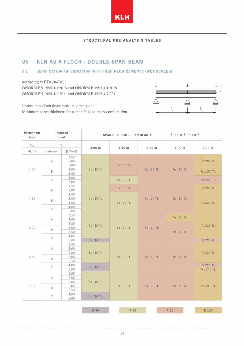
5.1 VERIFICATION OF VIBRATION WITH HIGH REQUIREMENTS (WET SCREED)
according to ETA-06/0138
ÖNORM EN 1995-1-1:2015 and ÖNORM B 1995-1-1:2015
ÖNORM EN 1995-1-2:2011 and ÖNORM B 1995-1-2:2011
Imposed load not favourable in some spans
Minimum panel thickness for a specific load-span-combination
nk
gk
ℓ1 ℓ2
S T R U C T U R A L P R E - A N A LY S I S T A B L E S
05 KLH AS A FLOOR - DOUBLE-SPAN BEAM
Permanent load
Imposed load
SPAN OF DOUBLE-SPAN BEAM ℓ1 ℓ
2 = 0,8*ℓ
1 to 1,0*ℓ
1
g2,k
nk
3,00 m 4,00 m 5,00 m 6,00 m 7,00 m[kN/m²] category [kN/m²]
1,00
A1,50
5s 110 TL5s 130 TL
5s 150 TL 5s 180 TL
7s 200 TL2,002,80
B3,00
7ss 210 TL3,50
C4,00
5s 130 TL 7ss 210 TL5,00
1,50
A1,50
5s 110 TL
5s 130 TL
5s 160 TL 5s 180 TL
7s 200 TL2,002,80
5s 130 TL 7s 220 TLB
3,003,50
C4,005,00
2,00
A1,50
5s 110 TL5s 130 TL 5s 160 TL
5s 190 TL
7s 220 TL
2,002,80
5s 190 TLB
3,003,50
C4,005,00 5s 110 TL 7s 220 TL
2,50
A1,50
5s 110 TL5s 130 TL 5s 160 TL 5s 190 TL
7s 220 TL2,002,80
B3,003,50
C4,00
5s 110 TL7s 220 TL
5,00 7ss 240 TL
3,00
A1,50
5s 110 TL5s 130 TL 5s 160 TL 5s 190 TL 7ss 240 TL
2,002,80
B3,003,50
C4,00
5s 110 TL5,00
R 30 R 60 R 90 R 120

S T R U C T U R A L P R E - A N A LY S I S T A B L E S
1 9
Service class 1
kdef = 0,6
Imposed load category A and B (ψ0 = 0,7 and ψ2 = 0,3): kmod = 0,8
Imposed load category C (ψ0 = 0,7 and ψ2 = 0,6): kmod = 0,9
Self-weight of KLH is already taken into account in the table.
Deflection limits according to ÖNORM EN 1995-1-1:2015
a) characteristic design situation: wQ,inst ≤ ℓ/300 and (wfin – wG,inst) ≤ ℓ/200
b) quasi-permanent structural design situation: wfin ≤ ℓ/250
Vibration verification according to ÖNORM B 1995-1-1:2015
a) floor slab class I: slab between different utilisation units (e.g. separating floor slabs for apartments or offices);
6 cm wet screed, floating on filler
b) limiting value of the frequency and stiffness criterion: f1,min ≥ 4,5 Hz; f1 ≥ fgr = 8 Hz; wstat ≤ wgr = 0,25 mm
c) modal damping ratio for cross-laminated timber floor slabs with floating screed and heavy floor structure: ζ = 4,0 %
d) limiting value acceleration (required at f1,min ≤ f1 ≤ fgr): arms ≤ agr = 0,05 m/s²
e) floor slab width (b) ≤ 1,2 * span (1,2*l)
Load-bearing capacity
a) verification of bending resistance
b) verification of shear resistance
Structural fire design (single -sided fire exposure)
Application of KLHdesigner based on the „reduced properties method“ according to ETA-06/0138.
a) charring rate β1 = 0,65 mm/min regular charring rate (charring within one single layer)
b) charring rate β2 = 1,00 mm/min increased charring rate (after the failure / falling off of one layer)
c) for local panel parts b < 300 mm higher charring rates are mandatory
d) the minimum panel thicknesses (for R 0) automatically reach fire resistance according to coloured marking
This table is only intended for structural pre-analysis purposes and does not replace necessary static calculations!

2 0
5.2 VERIFICATION OF VIBRATION WITH HIGH REQUIREMENTS (DRY SCREED)
according to ETA-06/0138
ÖNORM EN 1995-1-1:2015 and ÖNORM B 1995-1-1:2015
ÖNORM EN 1995-1-2:2011 and ÖNORM B 1995-1-2:2011
Imposed load not favourable in some spans
Minimum panel thickness for a specific load-span-combination
nk
gk
ℓ1 ℓ2
S T R U C T U R A L P R E - A N A LY S I S T A B L E S
Permanent load
Imposed load
SPAN OF DOUBLE-SPAN BEAM ℓ1 ℓ
2 = 0,8*ℓ
1 to 1,0*ℓ
1
g2,k
nk
3,00 m 4,00 m 5,00 m 6,00 m 7,00 m[kN/m²] category [kN/m²]
1,00
A1,50
5s 110 TL5s 140 TL
5s 160 TL5s 190 TL
7s 200 TL2,002,80
B3,00
7s 220 TL3,50
C4,00
5s 140 TL 5s 190 TL5,00
1,50
A1,50
5s 110 TL5s 140 TL
5s 170 TL5s 190 TL
7s 200 TL2,002,80
7s 220 TLB
3,003,50
C4,00
5s 140 TL 5s 190 TL5,00
2,00
A1,50
5s 110 TL5s 140 TL
5s 170 TL
5s 190 TL
7s 220 TL
2,002,80
5s 190 TLB
3,003,50
C4,00
5s 140 TL5,00 5s 110 TL 7s 220 TL
2,50
A1,50
5s 110 TL
5s 140 TL
5s 170 TL 5s 190 TL7s 220 TL
2,00
5s 140 TL
2,80
B3,003,50
C4,00
5s 110 TL7s 220 TL
5,00 7ss 240 TL
3,00
A1,50
5s 110 TL5s 150 TL 5s 170 TL 5s 190 TL 7ss 240 TL
2,002,80
B3,003,50
C4,00
5s 110 TL5,00
R 30 R 60 R 90 R 120

S T R U C T U R A L P R E - A N A LY S I S T A B L E S
2 1
Service class 1
kdef = 0,6
Imposed load category A and B (ψ0 = 0,7 and ψ2 = 0,3): kmod = 0,8
Imposed load category C (ψ0 = 0,7 and ψ2 = 0,6): kmod = 0,9
Self-weight of KLH is already taken into account in the table.
Deflection limits according to ÖNORM EN 1995-1-1:2015
a) characteristic design situation: wQ,inst ≤ ℓ/300 and (wfin – wG,inst) ≤ ℓ/200
b) quasi-permanent structural design situation: wfin ≤ ℓ/250
Vibration verification according to ÖNORM B 1995-1-1:2015
a) floor slab class I: slab between different utilisation units (e.g. separating floor slabs for apartments or offices);
dry screed, floating on heavy filler (at least 60 kg/m²)
b) limiting value of the frequency and stiffness criterion: f1,min ≥ 4,5 Hz; f1 ≥ fgr = 8 Hz; wstat ≤ wgr = 0,25 mm
c) modal damping ratio for cross-laminated timber floor slabs with floating screed and heavy floor structure: ζ = 4,0 %
d) limiting value acceleration (required at f1,min ≤ f1 ≤ fgr): arms ≤ agr = 0,05 m/s²
e) floor slab width (b) ≤ 1,2 * span (1,2*l)
Load-bearing capacity
a) verification of bending resistance
b) verification of shear resistance
Structural fire design (single -sided fire exposure)
Application of KLHdesigner based on „reduced properties method“ according to ETA-06/0138.
a) charring rate β1 = 0,65 mm/min regular charring rate (charring within one single layer)
b) charring rate β2 = 1,00 mm/min increased charring rate (after the failure / falling off of one layer)
c) for local panel parts b < 300 mm higher charring rates are mandatory
d) the minimum panel thicknesses (for R 0) automatically reach fire resistance according to coloured marking
This table is only intended for structural pre-analysis purposes and does not replace necessary static calculations!
2 2
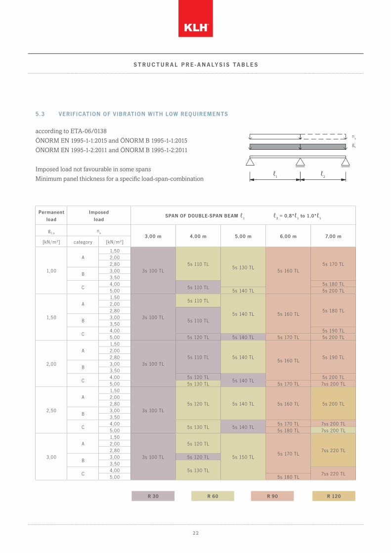
5.3 VERIFICATION OF VIBRATION WITH LOW REQUIREMENTS
according to ETA-06/0138
ÖNORM EN 1995-1-1:2015 and ÖNORM B 1995-1-1:2015
ÖNORM EN 1995-1-2:2011 and ÖNORM B 1995-1-2:2011
Imposed load not favourable in some spans
Minimum panel thickness for a specific load-span-combination
nk
gk
ℓ1 ℓ2
S T R U C T U R A L P R E - A N A LY S I S T A B L E S
Permanent load
Imposed load
SPAN OF DOUBLE-SPAN BEAM ℓ1 ℓ
2 = 0,8*ℓ
1 to 1,0*ℓ
1
g2,k
nk
3,00 m 4,00 m 5,00 m 6,00 m 7,00 m[kN/m²] category [kN/m²]
1,00
A1,50
3s 100 TL5s 110 TL
5s 130 TL5s 160 TL
5s 170 TL2,002,80
B3,003,50
C4,00
5s 110 TL5s 180 TL
5,00 5s 140 TL 5s 200 TL
1,50
A1,50
3s 100 TL
5s 110 TL
5s 140 TL 5s 160 TL5s 180 TL
2,002,80
5s 110 TLB3,003,50
C4,00 5s 190 TL5,00 5s 120 TL 5s 140 TL 5s 170 TL 5s 200 TL
2,00
A1,50
3s 100 TL5s 110 TL 5s 140 TL
5s 160 TL5s 190 TL
2,002,80
B3,003,50
C4,00 5s 120 TL
5s 140 TL5s 200 TL
5,00 5s 130 TL 5s 170 TL 7ss 200 TL
2,50
A1,50
3s 100 TL5s 120 TL 5s 140 TL 5s 160 TL 5s 200 TL
2,002,80
B3,003,50
C4,00
5s 130 TL 5s 140 TL5s 170 TL 7ss 200 TL
5,00 5s 180 TL 7ss 200 TL
3,00
A1,50
3s 100 TL
5s 120 TL
5s 150 TL5s 170 TL
7ss 220 TL2,002,80
B3,00 5s 120 TL3,50
5s 130 TLC
4,007ss 220 TL
5,00 5s 180 TL
R 30 R 60 R 90 R 120

S T R U C T U R A L P R E - A N A LY S I S T A B L E S
2 3
Service class 1
kdef = 0,6
Imposed load category A and B (ψ0 = 0,7 and ψ2 = 0,3): kmod = 0,8
Imposed load category C (ψ0 = 0,7 and ψ2 = 0,6): kmod = 0,9
Self-weight of KLH is already taken into account in the table.
Deflection limits according to ÖNORM EN 1995-1-1:2015
a) characteristic design situation: wQ,inst ≤ ℓ/300 and (wfin – wG,inst) ≤ ℓ/200
b) quasi-permanent structural design situation: wfin ≤ ℓ/250
Vibration verification according to ÖNORM B 1995-1-1:2015
a) floor slab class II: slab within the utilisation unit (e.g. detached house); floating wet screed (even without filler);
dry screed, floating on heavy filler (at least 60 kg/m²)
b) limiting value of the frequency and stiffness criterion: f1,min ≥ 4,5 Hz; f1 ≥ fgr = 6 Hz; wstat ≤ wgr = 0,50 mm
c) modal damping ratio for cross-laminated timber floor slabs with floating screed and heavy floor structure: ζ = 4,0 %
d) limiting value acceleration (required at f1,min ≤ f1 ≤ fgr): arms ≤ agr = 0,10 m/s²
e) floor slab width (b) ≤ 1,2 * span (1,2*l)
Load-bearing capacity
a) verification of bending resistance
b) verification of shear resistance
Structural fire design (single -sided fire exposure)
Application of KLHdesigner based on the „reduced properties method“ according to ETA-06/0138.
a) charring rate β1 = 0,65 mm/min regular charring rate (charring within one single layer)
b) charring rate β2 = 1,00 mm/min increased charring rate (after the failure / falling off of one layer)
c) for local panel parts b < 300 mm higher charring rates are mandatory
d) the minimum panel thicknesses (for R 0) automatically reach fire resistance according to coloured marking
This table is only intended for structural pre-analysis purposes and does not replace necessary static calculations!

2 4
according to ETA-06/0138
ÖNORM EN 1995-1-1:2015 and ÖNORM B 1995-1-1:2015
ÖNORM EN 1995-1-2:2011 and ÖNORM B 1995-1-2:2011
Minimum panel thickness for a specific load-span-combination
μ•sk
gk
ℓ
S T R U C T U R A L P R E - A N A LY S I S T A B L E S
06 KLH AS A ROOF - SINGLE-SPAN BEAM
Permanent load
Snow load on roof
SPAN OF SINGLE-SPAN BEAM ℓ
g2,k
s = μ*sk
3,00 m 4,00 m 5,00 m 6,00 m 7,00 m[kN/m²] [kN/m²]
0,50
1,00 3s 60 TL 3s 80 TL 3s 100 TL 3s 120 TL 5s 140 TL2,00 3s 70 TL 3s 90 TL 3s 120 TL 5s 140 TL 5s 160 TL3,00
3s 80 TL3s 100 TL 5s 130 TL 5s 150 TL 5s 180 TL
4,00 3s 110 TL 5s 140 TL 5s 170 TL 5s 200 TL5,00 3s 90 TL 3s 120 TL 5s 150 TL 5s 180 TL 7ss 210 TL6,00
3s 100 TL5s 130 TL 5s 160 TL 5s 200 TL 7ss 220 TL
7,00 5s 140 TL 5s 170 TL 7ss 200 TL 7ss 230 TL
1,00
1,003s 70 TL
3s 90 TL 3s 100 TL 5s 130 TL 5s 160 TL2,00 3s 100 TL 3s 120 TL 5s 150 TL 5s 180 TL3,00 3s 80 TL 3s 110 TL 5s 140 TL 5s 160 TL 5s 190 TL4,00
3s 90 TL 3s 120 TL5s 150 TL 5s 180 TL 7ss 200 TL
5,005s 160 TL
5s 190 TL 7ss 210 TL6,00
3s 100 TL5s 130 TL
7ss 200 TL7ss 220 TL
7,00 5s 140 TL 5s 170 TL 7ss 230 TL
1,50
1,00 3s 70 TL 3s 90 TL 3s 120 TL 5s 150 TL 5s 180 TL2,00
3s 80 TL3s 100 TL 5s 130 TL 5s 160 TL 5s 190 TL
3,00 3s 110 TL 5s 140 TL 5s 170 TL 5s 200 TL4,00 3s 90 TL 3s 120 TL 5s 150 TL 5s 180 TL 7ss 210 TL5,00
3s 100 TL5s 130 TL 5s 160 TL 5s 200 TL 7ss 220 TL
6,005s 140 TL
5s 170 TL 7ss 200 TL 7ss 230 TL7,00 3s 110 TL 5s 180 TL 7ss 210 TL 7ss 240 TL
2,00
1,003s 80 TL
3s 100 TL 5s 130 TL 5s 160 TL5s 200 TL
2,00 3s 110 TL 5s 140 TL 5s 170 TL3,00
3s 90 TL 3s 120 TL5s 150 TL 5s 180 TL 7ss 200 TL
4,00 5s 160 TL 5s 190 TL 7ss 210 TL5,00
3s 100 TL5s 130 TL
5s 170 TL 7ss 200 TL7ss 220 TL
6,005s 140 TL
7ss 230 TL7,00 3s 110 TL 5s 180 TL 7ss 210 TL 7ss 240 TL
2,50
1,00 3s 80 TL 3s 110 TL 5s 140 TL 5s 170 TL7ss 200 TL
2,003s 90 TL 3s 120 TL 5s 150 TL
5s 180 TL3,00 5s 190 TL 7ss 210 TL4,00
3s 100 TL5s 130 TL 5s 160 TL 5s 200 TL 7ss 220 TL
5,005s 140 TL
5s 170 TL 7ss 200 TL 7ss 230 TL6,00
3s 110 TL5s 180 TL 7ss 210 TL 7ss 240 TL
7,00 5s 150 TL 5s 190 TL 7ss 220 TL 7ss 250 TL
R 0 R 30 R 60 R 90 R 120

Service class 1
kdef = 0,6
Snow load at an altitude ≤ 1000 m above sea level (ψ0 = 0,5 and ψ2 = 0,0): kmod = 0,9
Self-weight of KLH is already taken into account in the table.
Maximum roof inclination 15°
Deflection limits according to ÖNORM EN 1995-1-1:2015
a) characteristic design situation: wQ,inst ≤ ℓ/300 and (wfin – wG,inst) ≤ ℓ/200
b) quasi-permanent structural design situation: wfin ≤ ℓ/250
Load-bearing capacity
a) verification of bending resistance
b) verification of shear resistance
Structural fire design (single -sided fire exposure)
Application of KLHdesigner based on the „reduced properties method“ according to ETA-06/0138.
a) charring rate β1 = 0,65 mm/min regular charring rate (charring within one single layer)
b) charring rate β2 = 1,00 mm/min increased charring rate (after the failure / falling off of one layer)
c) for local panel parts b < 300 mm higher charring rates are mandatory
d) the minimum panel thicknesses (for R 0) automatically reach fire resistance according to coloured marking
This table is only intended for structural pre-analysis purposes and does not replace necessary static calculations!
S T R U C T U R A L P R E - A N A LY S I S T A B L E S
2 5
2 6
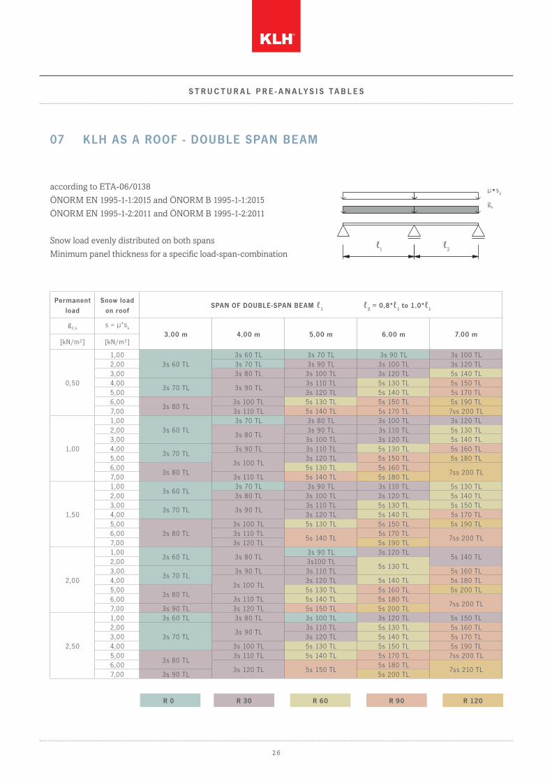
according to ETA-06/0138
ÖNORM EN 1995-1-1:2015 and ÖNORM B 1995-1-1:2015
ÖNORM EN 1995-1-2:2011 and ÖNORM B 1995-1-2:2011
Snow load evenly distributed on both spans
Minimum panel thickness for a specific load-span-combination
μ•sk
gk
ℓ1 ℓ2
S T R U C T U R A L P R E - A N A LY S I S T A B L E S
07 KLH AS A ROOF - DOUBLE SPAN BEAM
Permanent load
Snow load on roof
SPAN OF DOUBLE-SPAN BEAM ℓ1 ℓ
2 = 0,8*ℓ
1 to 1,0*ℓ
1
g2,k
s = μ*sk
3,00 m 4,00 m 5,00 m 6,00 m 7,00 m[kN/m²] [kN/m²]
0,50
1,003s 60 TL
3s 60 TL 3s 70 TL 3s 90 TL 3s 100 TL2,00 3s 70 TL 3s 90 TL 3s 100 TL 3s 120 TL3,00 3s 80 TL 3s 100 TL 3s 120 TL 5s 140 TL4,00
3s 70 TL 3s 90 TL3s 110 TL 5s 130 TL 5s 150 TL
5,00 3s 120 TL 5s 140 TL 5s 170 TL6,00
3s 80 TL3s 100 TL 5s 130 TL 5s 150 TL 5s 190 TL
7,00 3s 110 TL 5s 140 TL 5s 170 TL 7ss 200 TL
1,00
1,003s 60 TL
3s 70 TL 3s 80 TL 3s 100 TL 3s 120 TL2,00
3s 80 TL3s 90 TL 3s 110 TL 5s 130 TL
3,00 3s 100 TL 3s 120 TL 5s 140 TL4,00
3s 70 TL3s 90 TL 3s 110 TL 5s 130 TL 5s 160 TL
5,003s 100 TL
3s 120 TL 5s 150 TL 5s 180 TL6,00
3s 80 TL5s 130 TL 5s 160 TL
7ss 200 TL7,00 3s 110 TL 5s 140 TL 5s 180 TL
1,50
1,003s 60 TL
3s 70 TL 3s 90 TL 3s 110 TL 5s 130 TL2,00 3s 80 TL 3s 100 TL 3s 120 TL 5s 140 TL3,00
3s 70 TL 3s 90 TL3s 110 TL 5s 130 TL 5s 150 TL
4,00 3s 120 TL 5s 140 TL 5s 170 TL5,00
3s 80 TL3s 100 TL 5s 130 TL 5s 150 TL 5s 190 TL
6,00 3s 110 TL5s 140 TL
5s 170 TL7ss 200 TL
7,00 3s 120 TL 5s 190 TL
2,00
1,003s 60 TL 3s 80 TL
3s 90 TL 3s 120 TL5s 140 TL
2,00 3s100 TL5s 130 TL
3,003s 70 TL
3s 90 TL 3s 110 TL 5s 160 TL4,00
3s 100 TL3s 120 TL 5s 140 TL 5s 180 TL
5,003s 80 TL
5s 130 TL 5s 160 TL 5s 200 TL6,00 3s 110 TL 5s 140 TL 5s 180 TL
7ss 200 TL7,00 3s 90 TL 3s 120 TL 5s 150 TL 5s 200 TL
2,50
1,00 3s 60 TL 3s 80 TL 3s 100 TL 3s 120 TL 5s 150 TL2,00
3s 70 TL3s 90 TL
3s 110 TL 5s 130 TL 5s 160 TL3,00 3s 120 TL 5s 140 TL 5s 170 TL4,00 3s 100 TL 5s 130 TL 5s 150 TL 5s 190 TL5,00
3s 80 TL3s 110 TL 5s 140 TL 5s 170 TL 7ss 200 TL
6,003s 120 TL 5s 150 TL
5s 180 TL7ss 210 TL
7,00 3s 90 TL 5s 200 TL
R 0 R 30 R 60 R 90 R 120
S T R U C T U R A L P R E - A N A LY S I S T A B L E S
2 7
Service class 1
kdef = 0,6
Snow load at an altitude ≤ 1000 m above sea level (ψ0 = 0,5 and ψ2 = 0,0): kmod = 0,9
Self-weight of KLH is already taken into account in the table.
Maximum roof inclination 15°
Deflection limits according to ÖNORM EN 1995-1-1:2015
a) characteristic design situation: wQ,inst ≤ ℓ/300 and (wfin – wG,inst) ≤ ℓ/200
b) quasi-permanent structural design situation: wfin ≤ ℓ/250
Load-bearing capacity
a) verification of bending resistance
b) verification of shear resistance
Structural fire design (single -sided fire exposure)
Application of KLHdesigner based on the „reduced properties method“ according to ETA-06/0138.
a) charring rate β1 = 0,65 mm/min regular charring rate (charring within one single layer)
b) charring rate β2 = 1,00 mm/min increased charring rate (after the failure / falling off of one layer)
c) for local panel parts b < 300 mm higher charring rates are mandatory
d) the minimum panel thicknesses (for R 0) automatically reach fire resistance according to coloured marking
This table is only intended for structural pre-analysis purposes and does not replace necessary static calculations!
N O T E S


For love of nature
Pr inted on ecolog ical ly f r iendly paper
K L H M A S S I V H O L Z G M B H
Gewerbes t raße 4 | 8842 Teufenbach -Katsch | Aus t r ia
Tel +43 (0)3588 8835 0 | Fax +43 (0)3588 8835 20
of f [email protected] | www.k lh.at


