Download - SSC16-WK-11 - CubeSatShop

Voss 1 30th Annual AIAA/USU
Conference on Small Satellites
SSC16-WK-11
Globalstar Link: From Reentry Altitude and Beyond
Hank D. Voss, Jeff F. Dailey, Matthew B. Orvis,
NearSpace Launch, Inc. (NSL)
8702 E 825 S, Upland, IN 46989; 765-618-3813
[email protected], 765-998-8942
Arthur J. White and Stefan Brandle
Taylor University
Computer Science & Engineering Department, Upland, IN 46989; 765-998-5165
ABSTRACT
Three CubeSats flown in the past two years have successfully mapped Globalstar performance over the
altitude range 100 km to 700 km. The Globalstar constellation provides “Anywhere and Anytime”
visibility to satellites and is ideal for CubeSats, constellations, and formation flying missions. Globalstar
capacity is designed for 2500 channels per Globalstar satellite, potentially enabling hundreds to thousands
of simultaneous communication to satellites. Capacity would then extend from the ground to potentially
above the Globalstar LEO constellation at 1400km. TSAT (2U) made real-time plasma density and
diagnostic measurements in the Extremely Low-Earth Orbit (ELEO) ionospheric region 350 to 110 km
for new in-situ Space Weather mapping. TSAT heated at a rate of 20 degrees/min. on reentry at 110 km
(reentry physics), yet it maintained a good real-time link with ground stations in Canada and Venezuela
where it is believed to have re-entered. The NSL Globalstar flight products now permit new experiments
to ELEO orbits in addition to releasing drop radiosondes to explore the Upper Atmosphere (Mesosphere)
coupling with the lower atmosphere. Preliminary results are presented from the Globalstar Experiment
and Risk Reduction Satellites (GEARRS1 and GEARRS2). GEARRS1 (3U) was launched from the ISS
and verified the Globalstar CDMA protocol and Duplex SMS messaging. GEARRS2 (3U) was launched
with an Atlas rocket on May 20, 2015 into a 350 by 700 km orbit and the Simplex communication and
instrumentation operated well for 9 months beyond the mission expected lifetime (high TRL and radiation
tolerant). Improved global coverage maps of the Simplex and Duplex performance are presented. Global
maps of Duplex RF pulse data indicate that the Duplex may have good global coverage when on a 3 axis
stabilized satellite to permit necessary connect time. Using a small permanent magnet for attitude control,
the two patch antennas (1.616 GHz) and loss-cone energetic particle detector point up and down the
earth’s magnetic field lines. The three SSD detectors mapped the precipitating and trapped particle flux
in the aurora zone, the SAMA, the trapping boundary, and the internal penetrating radiation dose. Several
new Globalstar flight radios are manifested for launch with three axis stabilization, so that Duplex large
file transfer can be characterized. TSAT and GEARRS data indicate a strong side lobe link that may reach
to high MEO altitudes

Voss 2 30th Annual AIAA/USU
Conference on Small Satellites
INTRODUCTION
This paper reports on the new
capabilities and applications of the
NSL-Globalstar Simplex and
Duplex flight communication links
for new space investigations. The
first Globalstar flight results and
coverage maps were presented (1)
on TSAT which was launched on
April 18, 2014. Preliminary
results from the recent Globalstar
Experiment and Risk Reduction
Satellites (GEARRS1 and
GEARRS2) are reviewed and the
analysis augmented from the
previous presentations on
GEARRS1 (2) and GEARRS2 (3).
Figure 1 summarizes aspects of
these pioneering flights. In
addition, an effort is made to
present information and products
so that other researchers and
students can efficiently implement
Globalstar space flight and
ground segment products into
their space systems in a matter of
weeks.
The $2B Globalstar Constellation of over 32 LEO
satellites (4) at 1400 km provides terrestrial global data
and voice services (Duplex) for ~300,000 customers.
The Simplex units monitor data (e.g. facilities, wildlife,
oil rigs, gas pipe-lines, shipping containers and
endangered animals).
NearSpace Launch, Inc. (NSL) advanced the EyeStar
flight modem processor product for TSAT, GEARRS,
and other satellites & the EyePod product for high-
altitude ballooning. NSL developed a relationship with
Globalstar engineers and management and is an official
Value Added Reseller (VAR) for the past several years
with its flight approved and FCC approved satellite
radios and ground segment. NSL has flown six EyeStar
units with 100% success and now > 370 balloon
EyePod launches with over 99% data/recovery success.
Data links include the Globalstar and NSL network
(Simplex and Duplex). Globalstar Code Division
Multiple Access (CDMA) provides extremely high
signal to noise ratio using a wide bandwidth and a
pseudorandom noise (PN) code that is suitable for high
velocity satellites and encryption. Satellite commanding
and data downlinks are maintained by the Globalstar
professional ground stations.
The TSAT satellite was designed to better understand
the E and F region global ionosphere below 325 km and
down into the heating region below 120km. This
uncharted new region for investigation is called the
Extremely Low Earth Orbit (or ELEO) region, and is
relevant to the understanding of space weather,
atmospheric models, climate, global electric circuit,
remote sensing, and intelligence gathering. In order to
accomplish this goal in near real-time, the EyeStar
radio system does not need store and forward data with
associated long delays. This is very important in the
forecasting and in the reentry ELEO region.
Communication Priority
Communication problems dominate in the small
satellite development phase and are responsible for
many flight failures. Communication considerations
include:
1) Simplifying the complexity of the communication
system; a sub-system that involves low power
transceivers with low mass and size and RF connectors
and cables.
2) Exclusion of spacecraft protruding antennas, and
risky deployment mechanisms.
Figure 1: Three successful student and commercial CubeSats that used the
Globalstar Simplex and Duplex links for the first time. Mission success is
assured, performance increased, and minimal resources required.

Voss 3 30th Annual AIAA/USU
Conference on Small Satellites
Figure 2: Example of four CubeSat constellation using the Globalstar communication and GPS networks
for near real-time and absolute position determination. Constellation control is managed on the ground
segment.
3) Remove requirement for high-gain, expensive
tracking ground stations with associated software and
operations cost for a research grade ground segment.
4) Infrequent and short line-of-sight overpasses for
conventional ground stations.
4) Maintaining a commercial and research grade FCC
license versus a limited Ham amateur approval.
5) Difficulties associated with international radio
community coordination and licenses.
6) Waiting hours to days after initial turn on to react to
health and safety data.
7) Inability to observe a tumbling satellite after initial
turn on and command it in emergencies.
8) Need for 24/7 commanding and satellite visibility.
9) Difficulties of operating a constellation of satellites
with multiple ground stations and disjointed data base.
10) Rapid identification of satellite number from
conflicting Two Line Elements (TLE) series for
analysis and tracking.
New Paradigm
The TSAT, GEARRS1, and GEARRS2 spacecraft
introduced a new paradigm using the existing
Globalstar network of phone satellites to initiate
satellite-to-satellite cross-links. The Globalstar-NSL
ground segment also unifies the various Globalstar
EyeStar radios into a common and synchronized
dataset. It is essential that the data from all satellite
ground stations be unified and time-synchronized for
multipoint measurements. The EyeStar radios and
Globalstar-NSL ground network greatly simplify data
correlation with satellite positioning. Using a
communication model similar to the one employed on
TSAT promises high reward potential as the
opportunity for mission success greatly increases
because of nearly global coverage of spacecraft
telemetry with low latency, and no mission specific
ground infrastructure beyond a data server.
In Figure 2 the Globalstar constellation is shown giving
24/7 connectivity to a small constellation of four
CubeSats. With its few second latency, the Globalstar
network can assume much of the direct control of
constellations from ground operations. This can
significantly reduce the risk of orbit operations with
adaptability, optimization, and at much lower cost.
Globalstar Data Capacity
A diagram of the Globalstar constellation in relation to
other satellites and important space regions is shown in
Figure 3. The red arrows indicate the link directionality
and the dashed links show unknown limits. With low
cost aerodynamic CubeSats, ion engines, and the
Globalstar low data latency, the new underexplored
regions listed with a question mark are open for
detailed study.
Globalstar has sufficient current network and system
capacity, as TSAT’s conservative communications
regimen did not even begin to register as a significant
data source on the Globalstar network. CubeSat
communications performance apparently won’t be
impacted by any system capacity issues for either

Voss 4 30th Annual AIAA/USU
Conference on Small Satellites
Simplex or Duplex communications. Even if there were
hundreds of CubeSats in orbit, all simultaneously using
the Globalstar network, the communications load would
be just a tiny fraction of the traffic that Globalstar
currently handles. There are currently no capacity
issues at any individual gateways, nor are there
anticipated to be any future capacities due to the
addition of CubeSats. The Globalstar system appears to
have capacity to handle many CubeSats transmitting
thousands of packets per day.
Figure 3: Visual nonlinear scale of the Globalstar constellation in relation to orbit regions, ionosphere
regions, atmosphere regions, other satellites, and ground operations. Globalstar links are shown with red
arrows indicating Simplex and Duplex directionality. The dashed links show new link investigations. The
question marks indicate uncharted regions near earth for fruitful CubeSat study.

Voss 5 30th Annual AIAA/USU
Conference on Small Satellites
DATA OPERATIONS
The NSL ground station technology (Figure 4) is
comprised of the following elements:
The Globalstar communications network
The NSL server
The web console
The web Application Program Interface (API)
The Front End Processor (FEP)
The Globalstar communications network provides the
actual ground-to-space link. All the normal radio link
management issues are delegated to Globalstar.
Figure 4: Overall Communications Architecture.
The NSL server communicates via the Globalstar
network to send and receive satellite data. All data is
logged and archived on the server. The server database
performs real-time replication to a backup server. The
typical full path latency for Simplex data from satellite
to the NSL server is under 30 seconds.
Figure 5: Web Console Simplex Telemetry Display.
For those who desire, the NSL web console (Figure 5 &
6) permits viewing, graphing, zooming, translation, and
downloading Simplex telemetry data (commonly, 36 or
45 bytes per packet). In order to display and download
meaningful Simplex telemetry data fields, the web
console code performs packet decommutation and
reverse quantization on the raw bytes to convert the
Simplex field values back to an approximation of the
original engineering unit values. The first byte of each
Simplex packet identifies the packet type and dictates
how the rest of the packet is to be processed, in a secure
manner, leveraging best industry practices.
The web console also handles interactive uploading and
downloading of files via the Duplex file transfer link, as
well as sending short commands (1-35 bytes) via the
SMS channel. Last, real-time tracking of balloon flight
locations and plotting on maps is also available using
the web console.
Figure 6: Web Console Simplex Telemetry Graphing.
The NSL server web API provides the programming
capability to send and receive all data streams over the
Internet. That includes receiving Simplex telemetry
packets, sending and receiving data files, sending SMS
commands, and the option of receiving link metadata.
Figure 7: Client Using FEP and Web Console.
The Front End Processor (FEP) provides the client with
TCP/IP-based sockets as a means for communicating
with a satellite (Figure 7). The entire communications

Voss 6 30th Annual AIAA/USU
Conference on Small Satellites
path is simplified to reading and writing using specified
ports on the FEP. The FEP uses the web API to perform
all communication with the NSL server, thus relieving
the client of a significant amount of programming. The
FEP also stores archival copies of the data and performs
optional encryption and decryption of data.
When interfacing with the FEP, the client configures
their client mission operations system (e.g., COSMOS)
to read and write the appropriate TCP/IP ports on the
FEP. This approach is similar to the traditional
approach that reads and writes serial lines to
communicate with a FEP, except that TCP/IP ports are
used instead. Multiple FEP configurations are possible:
at the low end, the FEP is configured for one mission
with just one Simplex or Duplex link. At the high end, a
FEP can be configured for multiple missions, each with
a mixture of multiple Simplex or Duplex units.
Additionally, the FEP architecture permits multiple
FEPs to run in parallel without interference for the
same mission. This architecture permits clients to easily
run one or more FEPs as hot backups as well as
providing distributed mission command and control.
Encryption
FIPS 140-2 validated cryptography must be used by
private-sector vendors who provide encryption for
sensitive but unclassified data in certain
regulated industries and branches of the United States
and Canadian governments (Ref. 7). FIPS 140-2
specifies procedures for validating encryption tools on
specified platforms. The NSL Front End Processor
(FEP) uses an embedded OpenSSL FIPS 140-2-
validated cryptographic module running on a RHEL 6
platform per FIPS 140-2 Implementation Guidance
Section G.5 guidelines. Consequently, the NSL FEP has
the capability of processing sensitive, unclassified data
for NASA, DOD, and other federal units.
The FEP encrypts serialized data going from the
customer to the satellite, and decrypts data going from
the satellite to the customer. Unencrypted data is held
only briefly in memory and on the data connection to
the customer software. At no point is sensitive data held
unencrypted on the NSL file system.
TSAT REENTRY REGION PROBING
CubeSats and constellation CubeSats using Globalstar
24/7 communication are now capable of unprecedented
low-altitude data and location tracking below 350 km
and in the reentry region.
TSAT Reentry results
At a TSAT location just west of Mexico (See Figure 8),
the CubeSat nose endplate surface temperature was
observed to be increasing at 20 deg./min. In Figure 9
the last TSAT packet was transmitted in real time at
110 km and sent through two Globalstar satellites.
Three ground stations received the data (Canada, Chile,
and Venezuela) and transferred it to the NSL servers for
console display.
TSAT TLE Discrepancy
Also shown in Figure 9 is the TLE altitude variation
(purple top curve). The 90 min oscillation of this curve
is due to the predicted apogee and perigee variation.
TSAT, a low priority tracked object, also found a
discrepancy and little information on the low altitude
near reentry compared to predicted TLEs (top purple
curve). The derived decay trajectories below 250 km
are also shown. The conclusion here is that because of
drag the TLEs do not reflect the actual altitude below
250 km, but the latitude and longitude are consistent
with the TSAT data.
TLE Identification Using Sensor Data
As a side note the TLE CubeSat identification can be a
long and tedious process when many CubeSats are
launched together without GPS. For TSAT and
GEARRS we were able to use in situ and remote sensor
data to identify our satellite in a cluster. In Figure 10
the GEARRS satellite was identified by plotting our
Figure 8: TSAT location of last data packets
(~110km) and illustrated bent pipe data paths to
the Globalstar satellites to gateways in Peru,
Venezuela, and Canada. (Ref. 15)

Voss 7 30th Annual AIAA/USU
Conference on Small Satellites
energetic particle or other sensor data with the TLEs of
the eight other satellites in our cluster. As shown in
Figure 8 the bottom panel tracks well with the known
particles in the South Atlantic Magnetic Anomaly
(SAMA) and the auroral oval seen
prominently in the south polar region.
Future satellites will use GPS (as prices
drop and interface complexity improves)
with the Globalstar network to quickly
identify satellites seconds after the RF is
allowed to turn on.
Dropsonde Exploration of Mesosphere
As Radiosondes have revolutionized our
understanding of the atmosphere over half
a century, a plethora of “Dropsondes”
may also revolutionize our understanding
of the Mesophere. A cluster of small
Mesosphere probes may be released near
the CubeSat reentry point after the main
CubeSat shell has taken the brunt of the
deceleration and heating. The idea here is
to then release an autonomous
Mesospheric probe that maintains some of
the main bus systems (e.g. Globalstar
radios, GPS, fresh battery, temp sensors,
plasma probe, energetic particles) and
freefalls and glides to the lower
atmosphere while transmitting data and
being tracked. This idea has been implemented by the
early ELEO region DOD satellites (Corona, 1960’s) to
drop film packages to earth.
As illustrated in Figure 11 the aerodynamic CubeSat
(much like TSAT) decelerates and heats in the reentry
region. It includes a thermal heat shield and insulation
before the Dropsonde located in the rear as shown.
Because the ionization wake and antennas are in the
rear, the link should remain connected to the Globalstar
network during most of the blackout region. Then at a
predetermined point based on acceleration and/or
temperature, the Dropsonde is released with a
mechanism to deploy a Kevlar drag chute on stiff
Carbon fiber tubes which will also act as an
atmospheric parachute for safe landing. See the right
two drawings in Figure 11 of the Dropsonde package
and the Dropsonde as it is deployed. The probes could
continue to operate as a ground or ocean probe. Of
course much more analysis is required and a prototype
could be flown to test some of these concepts.
Figure 9: TSAT reentry flight paths: Solid blue line is archive
TLEs/SGP4 model, red line is TSAT drag model, dashed and
dotted lines are derived from models Ref. (10) and Ref. (12).
TSAT Reentry time at 75 km is 4:01 UT by NORAD, last packet
received at 110 km at 3:39 UT, and previous packet at 140 km
at 00:41 UT.
Figure 10: The upper panel shows GEARRS2
satellite for one of the eight TLEs in our cluster.
After a day or so our particle data (bottom panel)
lines up best (SAMA and Oval) with our now
identified TLE.
(b)
(a)

Voss 8 30th Annual AIAA/USU
Conference on Small Satellites
GEARRS1 LAUNCH AND ACCOMPLISHMENTS
Globalstar Experiment and Risk Reduction Satellite
(GEARRS, Figure 12) was an exploratory mission by
NSL and the AFRL to provide detailed analysis of the
global extent of coverage for Simplex and Duplex
TT&C. First results were given at the Cal Poly
workshop in 2015 and the Small Sat conference in 2015
(2). GEARRS data products help further inform the
small satellite community about the potential of the
Globalstar Network as an operations alternative or a
helpful augment to the traditional operations paradigm.
GEARRS1 was launched on the Orbital Sciences ORB-
2 resupply mission to the ISS via the Space Test
Program who contracted the commercial launch
services provider NanoRacks LLC. Launch from the
ISS was delayed until Feb of 2015 due to a launcher
problem. The design
and build mission in its
entirety from concept to
NanoRacks integration
delivery lasted 94 days.
This speaks to the
responsiveness of a
highly integrated team
willing to assess and
execute the mission
success criteria. To that
end, it also speaks to
the ability of the launch
services providers STP
and NanoRacks
providing a clear
closed-form process to
follow enabling a quick
turn mission.
Similar to TSAT,
GEARRS1 includes a Langmuir Plasma Probe for
measuring electron density. The input electrometer
covers 6 orders of magnitude using a log amplifier.
Eight temperature sensors are included, along with
normal health and sat safety voltage and current
monitoring. In addition, Duplex status is also
transmitted.
The driving data products required three radios on the
GEARRS space vehicle. A Simplex radio provides
engineering telemetry feedback at a constant cadence
for the GEARRS team to analyze Simplex throughput
around the globe. A Duplex radio connected to a
separate Simplex beacon enables characterization of
Duplex connectivity to the network, and coarse signal
strength. Also having the Duplex unit allows for an
assessment of uplink command authority to the space
vehicle around the globe from IP based ground
terminals.
The Globalstar Experiment and Risk Reduction
Satellite (GEARRS1) was designed to completely run
off battery for a short 2-3 day mission life to prove the
EyeStar Duplex performance in space and reduce risk
on many flight components (EPS, new Globalstar links,
hybrid antennas, new ground control system, and flight
software) for other missions. After GEARRS’
successful ISS launch at 8:20PM ET or 6:20 MT on
Tuesday March 3 (1:20 UT March 4) the first Simplex
packet was received at 2:48 UT and arrived 58 minutes
later than expected. This hour delay was likely due to
the battery charge below the 6.2 V battery trip off point.
All GEARRS systems appeared to become operational
and without resets to the flight processor sequence
counter. After several hours of solar cell charging the
Figure 11: Concept Dropsonde released from 3U CubeSat for exploring the
Mesosphere.
Attitude Control
BatteriesSensors
DropsondeComm,
PIN DiodesPlasma
Kevlar Parachute& Carbon Rods
Fiberglass Bulkhead & Heatshield
Globalstar Duplex 2
Globalstar Simplex 2
Plasma Probe
Globalstar Duplex 1
Globalstar Simplex 1(beneath)
Solar Panels
Insulation
3U Structure
Fiberglass Bulkhead & Heatshield
Globalstar Duplex 1
Globalstar Simplex 1
Parachute
Slots for side antennae to slide out
Figure 12: GEARRS1 at delivery showing a Simplex
patch antenna on the solar array panel and the plasma
probe on the end cap. A second Simplex unit is on the
down facing end cap. The Duplex antenna is not shown.

Voss 9 30th Annual AIAA/USU
Conference on Small Satellites
weak battery tripped on. On orbit 3 the Duplex
received 19 SMS commands over a 55 min period
mostly in eclipse and 12 of them were validated (63%)
Although the amount of data received was lower than
expected due to a one-year aged battery, almost all of
the GEARRS main objectives were achieved (hardware
risk reduction) and impressive Duplex and Simplex
performance observed for the first time. Fortunately,
GEARRS2 was scheduled to launch a few weeks later.
Preliminary GEARRS list of accomplishments and
Risk Reduction:
1. GEARRS complete system worked as an integrated
unit in space with much valuable data in spite of the
very low battery voltage at turn-on due to an
unexpected one-year delay without battery charging.
(All inhibits, EPS, three processors, two EyeStar
Globalstar Simplex units, one EyeStar Globalstar
Duplex unit, solar array panel, instruments, flight
software, and ground system).
2. For the first time the Globalstar Duplex unit works
in space with a high-gain active hybrid antenna. It was
tested for commanding and data quality with validation
of command and backhaul of command on Simplex.
Valuable data obtained on Duplex initialization times,
CDMA operation, and Gateway handoffs.
3. In one hour 12 of 19 sequential commands were
received and validated (63%) by the Duplex unit at low
power over all latitudes.
4. First dual EyeStar Globalstar Simplex units in space
with dual patch antennas working well.
5. CONOPS end-to-end real operations and testing
validated.
6. Solar Arrays added by NSL worked and kicked the
satellite on in first orbit with its much depleted batteries
and continued to add power to the batteries during
flight.
7. All flight Beacon, Duplex, and EPS processor
hardware and software working and flight tested for
AFRL missions.
8. All data transfer ground segment paths were
validated through Satellite-to-satellite, Satellite-to-
Gateways, Gateways to NSL backup servers, data
storage, ground software displays, and AFRL near real-
time data access.
9. Ground segment and Commanding Script data
software tested and working on orbit.
10. Visualization software for GEARRS data was
tested and improved.
11. Much more information obtained on Globalstar
Duplex efficient modes and network tuning.
12. GEARRS went into low power mode as
programmed. All sequences worked as programmed.
13. Indiana’s first commercial satellite
14. Passive permanent magnetic (0.3 Am2) attitude
observed to rotate spacecraft along B field direction in
correct direction after release from spacecraft
GEARRS2:
First results of the GEARRS2 mission were presented
at the Small Sat Conference 2015 (1).
The GEARRS2 Satellite was built on a quick 45 days
turn-around to back up the low battery on GEARRS1
mission and add some new data software and features.
Figure 13: GEARRS 2 Subsystem Layout.

Voss 10 30th Annual AIAA/USU
Conference on Small Satellites
GEARRS2 used the standard NSL 3U FastBus product
(Appendix 1): (Structure, EPS, G* links, mag., solar,
EMI enclosure, Thermal short, passive magnet). The
GEARRS2 photo in Figure 1 shows the Simplex and
Duplex patch antennas and the plasma probe on the end
cap.
In Figure 13 a CAD cutaway is shown of the external
and internal subsystems of GEARRS2.
GEARRS2 operated for 9 months from launch in LEO
(700 by 350 km orbit) with end-to-end space testing
and ground segment operations.
GEARRS DATA COVERAGE MAPS.
Raw data coverage maps are shown for the Simplex
Radio on GEARRS2 in Figure 14. In Figure 14 a
comparison is shown of the recent Globalstar ground
phone coverage map with the new Africa Ground
Station (first panel), the TSAT coverage map (second
panel), the GEARRS2 Coverage (third panel) and
energetic Particle data received on several passes. Note
improvement with high altitudes and a new Ground
station in Africa. Bottom panel: Example of STX-2
Simplex energetic particle data from several orbits of
GEARRS2. Small gaps in track show duty cycle of
transmitter and long gaps due to sun sync of 78 packets
of data sequence to save system power. Note the South
Atlantic Magnetic Anomaly (SAMA) and the Aurora
Oval. GEARRS Simplex coverage maps (Figure 15) are
very uniform over the entire earth with a weaker
coverage area in the Pacific Ocean. The 53 deg.
latitude cutoff is due to the GEARRS Sat. inclination
and not due to the
Globalstar link.
In Figures 16-17, the
top panel shows the
Globalstar Duplex
ground coverage and
the Duplex connects
/Signal strength
connects for the
Duplex unit when
the satellite was
spinning at 2 RPM
and pitching at 1
RPM. The second
panel shows the
Globalstar Duplex
ground map and the
SMS Duplex
Commanding. It
was very hard for
the Duplex unit to
get long enough
Figure 14: Simplex coverage maps from ground
from Globalstar, TSAT 2014 map, and
GEARRS2 2015 map. GEARRS2 particle map
showing aurora and South Atlantic Magnetic
Anomaly.
Figure 15: Simplex raw data packets received showing the unweighted but still very
uniform coverage. Note some of the weaker coverage areas over the oceans but is much
better than the Globalstar and coverage maps.

Voss 11 30th Annual AIAA/USU
Conference on Small Satellites
connections except when it
was over the major ground
stations because GEARRS was
spinning at a 2 RPM rate.
GEARRS2 actually became
locked on the magnetic field
with its passive magnet in the
third month of its flight but the
Duplex units were not
operational at that time.
The lower panel shows RF
binary files transmitted by the
Duplex based on a registration
command received by the
Duplex unit from the
Globalstar satellite. Since the
RF binary files were sent in a
fraction of a second the spin
motion was not an issue. Fast
RF Duplex Connects give a
uniform coverage around the
earth.
The fact that the fast RF
Duplex transmission were
initiated by the Globalstar
satellite during the registration
process and are evenly spread
out over the entire earth
similar to the Simplex
coverage it is anticipated that
when a CubeSat is stabilized
and in constant contact with
the Globalstar satellite that the
Duplex unit will have uniform
Global coverage! This will
have to be verified on a non-
spinning spacecraft.
EyeStar radios are now
planned for an upcoming
AFRL mission and upcoming
DARPA mission.
Figure 16-17: Top Panel first shows the Globalstar Duplex ground coverage and the Duplex
connects/Signal strength connects for the Duplex unit when the satellite was spinning at 2 RPM and
pitching at 1 RPM. The second panel shows the SMS Duplex Commanding. The lower panel shows RF
binary files transmitted by the Duplex based on a registration command received by the Duplex unit
from the Globalstar satellite. A uniform Duplex coverage map is expected for a non-spinning satellite.
Voss 12 30th Annual AIAA/USU
Conference on Small Satellites
CHARACTERIZING THE GLOBALSTAR GSP-
1720 MODEM: TERRESTRIAL TESTING
Investigation of the Globalstar GSP-1720 Duplex
modem capabilities has proceeded with both ground
characterization and testing in space via the GEARRS1
and GEARRS2 LEO flights. In all test environments,
NearSpace Launch's (NSL) GSP-1720 EyeStar
configuration (featuring an ARM processor running a
minimal Linux OS) has been characterized for both the
Simple Messaging System (SMS) and download file
transfer (communicating via TCP/IP over a PPP data-
link). The default configuration of the modem was
modified to accommodate separate data and control
channels so that simultaneous commanding and data
transmission are possible.
Call Connection Time
Testing to determine call connection elapsed time was
accomplished by running back-to-back call attempts
whenever a suitable signal strength was indicated by the
modem (Received Signal Strength Indicator of 4, or 2
or 3 and rising over time). During a three-hour period,
utilizing the original Duplex patch antenna (no longer
offered by Globalstar), 210 call attempts were made
(1.23 attempts per minute), with connected calls
resulting 192 times (91% connection rate). Connected
calls took an average of 15.51 seconds from initiation
of the call to connection, with a standard deviation of
1.95 seconds. During a one-hour period, utilizing the
new Duplex patch antenna (now the only antenna
available with the GSP-1720), 86 call attempts were
made (1.43 attempts per minute), with connected calls
resulting 82 times (95% call connection rate).
Connected calls took an average of 15.53 seconds from
initiation of the call to connect, with a standard
deviation of 2.45 seconds. Call connection time
appears to be a rather stable component of the entire file
transfer process. Data link establishment via PPP
averaged 6.8 seconds, with a standard deviation of 2.3
seconds. Expected time from initiation of a call to
establishment of the data link, before file transfer
protocol negotiation may begin, is generally around 22
seconds.
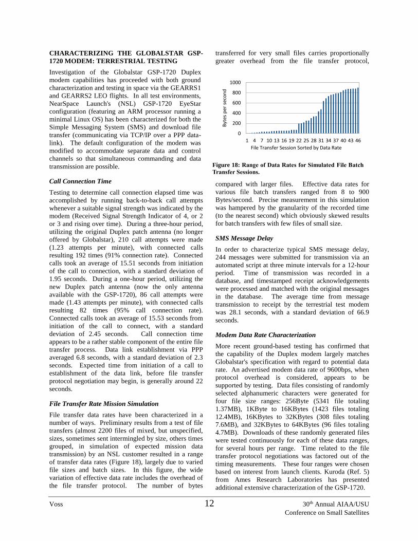
File Transfer Rate Mission Simulation
File transfer data rates have been characterized in a
number of ways. Preliminary results from a test of file
transfers (almost 2200 files of mixed, but unspecified,
sizes, sometimes sent intermingled by size, others times
grouped, in simulation of expected mission data
transmission) by an NSL customer resulted in a range
of transfer data rates (Figure 18), largely due to varied
file sizes and batch sizes. In this figure, the wide
variation of effective data rate includes the overhead of
the file transfer protocol. The number of bytes
transferred for very small files carries proportionally
greater overhead from the file transfer protocol,
compared with larger files. Effective data rates for
various file batch transfers ranged from 8 to 900
Bytes/second. Precise measurement in this simulation
was hampered by the granularity of the recorded time
(to the nearest second) which obviously skewed results
for batch transfers with few files of small size.
SMS Message Delay
In order to characterize typical SMS message delay,
244 messages were submitted for transmission via an
automated script at three minute intervals for a 12-hour
period. Time of transmission was recorded in a
database, and timestamped receipt acknowledgements
were processed and matched with the original messages
in the database. The average time from message
transmission to receipt by the terrestrial test modem
was 28.1 seconds, with a standard deviation of 66.9
seconds.
Modem Data Rate Characterization
More recent ground-based testing has confirmed that
the capability of the Duplex modem largely matches
Globalstar's specification with regard to potential data
rate. An advertised modem data rate of 9600bps, when
protocol overhead is considered, appears to be
supported by testing. Data files consisting of randomly
selected alphanumeric characters were generated for
four file size ranges: 256Byte (5341 file totaling
1.37MB), 1KByte to 16KBytes (1423 files totaling
12.4MB), 16KBytes to 32KBytes (308 files totaling
7.6MB), and 32KBytes to 64KBytes (96 files totaling
4.7MB). Downloads of these randomly generated files
were tested continuously for each of these data ranges,
for several hours per range. Time related to the file
transfer protocol negotiations was factored out of the
timing measurements. These four ranges were chosen
based on interest from launch clients. Kuroda (Ref. 5)
from Ames Research Laboratories has presented
additional extensive characterization of the GSP-1720.
Figure 18: Range of Data Rates for Simulated File Batch
Transfer Sessions.
1 4 7 10 13 16 19 22 25 28 31 34 37 40 43 46
0
200
400
600
800
1000
File Transfer Session Sorted by Data Rate
Byt
es p
er s
eco
nd

Voss 13 30th Annual AIAA/USU
Conference on Small Satellites
A single point test was also run to estimate download
time for a file of 10MB (again, randomly selected
alphanumeric characters). This download took about
18 hours and 20 minutes of elapsed time (5.2 hours of
actual file transfer time), over a series of 140 call
connections, yielding an effective transfer rate of 575
bytes per second, and an average of 77.2KBytes
transferred per call session segment (standard deviation
of 89.5 Bytes/second).
Figure 19 illustrates the effective data transfer rates for
the four file size categories, plus the 10MB file transfer.
In general, there is a trend of higher
data throughput for smaller file sizes.
Additional testing for optimization of
file size for data throughput will be
carried out for additional file size
ranges, and in future orbital
experiments.
GSP-1720 MODEM IN LEO
The performance of the Duplex
modem in LEO orbit was anticipated
to be comparable to performance
obtained through terrestrial tests.
Earlier concerns about Doppler
shifting causing unacceptable signal
loss was calculated to have only a
minor impact on the transmission
capabilities of the modem. Given the
reduction of distance between the
Duplex modem in space and the
Globalstar satellite constellation, the consequent
reduction of most atmospheric interference, and the
potential for the orbital path of the Duplex modem
satellite to often partially correspond to one or more of
the Globalstar constellation satellites (thus resulting in
longer duration signal lock), it was expected that file
transmission throughput would at least match, if not
exceed, throughput experienced in terrestrial tests.
GEARRS
GEARRS (Globalstar Experiment and Risk Reduction
Satellite) was the first NSL orbital test of the GSP-1720
Duplex modem. GEARRS was a 3U CubeSat, with 2
Globalstar STX-2 Simplex radios and one GSP-1720
Duplex modem, purposed for SMS commanding, but
not for file transfer. GEARRS launched from a
Nanoracks launcher aboard the ISS on March 4, 2015.
Because of repairs that needed to be applied to the ISS
Nanoracks launcher before GEARRS could be
deployed, GEARRS was in storage for nearly a year
without the possibility of recharging, and the batteries
were almost depleted when the satellite was deployed.
Despite this setback, there was enough power to send
204 science mission data records via the Simplex unit,
and 12 of 19 SMS messages from the ground were
received and acknowledged by the GEARRS GSP-1720
Duplex modem before the satellite went power
negative. Results of the GEARRS mission were
presented at the Cal Poly CubeSat Workshop in April,
2015. In short, GEARRS demonstrated the ability of
the GSP-1720 Duplex modem to receive SMS
messages while in low earth orbit.
GEARRS2
GEARRS2 was a 3U CubeSat with 2 Globalstar STX-2
Simplex radios and one GSP-1720 Duplex modem,
purposed for SMS commanding and file transfer,
launched in May of 2015 from a P-POD launcher on an
Atlas rocket. GEARRS2 achieved an elliptical orbit of
approximately 350 to 700 kilometers. GEARRS2
Figure 19: Data Transfer Rates for Four File Size
Ranges.
0200400600800
1000
Average Bytes/sec StDev Bytes/sec
Figure 20: GEARRS2 Spin Shortly After Deployment.

Voss 14 30th Annual AIAA/USU
Conference on Small Satellites
results were hampered by the flight dynamics of the
satellite, as both pitch and roll were apparently
imparted to the satellite upon deployment from the
launch vehicle. Figure 20 depicts magnetometer
instrument readings plotted over time, pointing to an
apparent roll rate of about 2 RPM and a pitch rate of
about 1 RPM. In order to understand possible effects of
these flight dynamic disturbances on the
communication effectiveness of the GSP-1720 Duplex
modem, a physical 2 axis flight dynamics simulator was
built to house and test the Duplex modem. Figure 21
depicts the simulator unit. The simulator was activated
for several hours, and data for the number of connection
attempts and connection durations were collected.
Figure 22 illustrates the results of testing, clearly
demonstrating the combined pitch and roll of the
satellite made signal acquisition of a sufficient duration
required for successful call placement, let alone
establishment of a data link, practically impossible. In
general, a duration of about 40 to 50 seconds is needed
to place the call, establish the data link, and initiate file
transfer. Although a single call was received from the
GEARRS2 GSP-1720 just after satellite deployment
(personal correspondence with Globalstar), the
combined roll and pitch of the satellite prevented data
link establishment, and also prevented any additional
calls from being received from the modem. File
transfer was essentially eliminated by the satellite's
flight dynamics. However, SMS commands were still
received by the Duplex modem, probably due to the
short duration terrestrial SMS transmission which
would occasionally align with the brief reception
window, sporadically presented by the rolling and
pitching satellite.
At 24 days into the mission, the communications
processor (but not the Duplex modem) ceased
functioning. This failure occurred after the spacecraft
had rebooted over 50 times due to low power
shutdown/solar insolation/restart cycles. The
communications processor failure prevented any
additional testing of the Duplex modem file transfer
capability, as it was anticipated that the modem might
be expected to start transferring files with the
achievement of more stable flight dynamics over time.
However, subsequent to the communications processor
failure, SMS messages were still being received by the
modem. Over the course of 56 days, 261 of 308 SMS
messages were received (84.7%). Average time from
transmission to acknowledgement of receipt was
unacceptably long due to the disturbed flight dynamics
and resultant disruption of communication with the
Duplex modem, and the increasingly intervals between
SMS retries employed automatically by the
Globalstar SMS transmission system. SMS
reception of the Duplex modem was
exceptional under the circumstances, although
timely receipt was greatly reduced (hours-days
delay versus normal seconds-minutes delay).
SCIENCE: ENERGETIC PARTICLES
Survey Data
Figure 23 shows a survey plot of most of the
raw sensor data collected on GEARRS2. The
subplots show the 3 magnetometer axes (Mag
X, Mag Y, and Mag Z), three energy particle
detectors (SSD Y external, SSDY internal, and
SSD Z), the voltage of the solar arrays, packet
count, and altitude. The energetic particle
detectors are three solid state detectors, two
Figure 21: 2-Axis Test Platform for GSP-1720
with pitch and roll motion.
Figure 22: Results of 2-axis Rotation Simulation.
82.3%
9.3%
57.7%
0.0%attempted insufficient
signal0.0%
10.0%
20.0%
30.0%
40.0%
50.0%
60.0%
70.0%
80.0%
90.0%
StationaryUpward
StationaryDownward
Roll 2 RPM Roll 2 RPMPitch 1 RPM

Voss 15 30th Annual AIAA/USU
Conference on Small Satellites
Figure 23: Example of existing survey plots for
GEARRS G* data received on 10 October 2015.
Top three panels show Magnetometer x,y,z with the
X axis locked on the magnetic field line. Two
Aurora Oval particle precipitation peaks shown on
either side of the polar cap. Lower panels voltage &
altitude.
Figure 25: GEARRS2 Solid State Detector data, for
the external and internal +y facing detector. This
shows the ratio of external/internal. Color indicates
the particle energy spectrum, ranging from heavy
“hard” spectra, to softer particles.
Figure 24: GEARRS2 Solid State Detector data, for
the external +y facing detector. Color indicates
particle counts per 1/4s. Note the high count region
over North America, the South Atlantic Anomaly,
and the aroural oval region.
facing the +y direction, one in the +z direction. In the
+y direction, one detector has no shielding in front,
earning it the “external” tag, while the other lies behind
the aluminum frame, giving it the “internal” tag. These
differences allow the measurement of all particles,
along with highly energetic particle that must penetrate
the aluminum shield.
Observing the three magnetic subplots, the satellite is
shown to be magnetically locked in the +x and +y axis,
and rotating slowly about the +z axis. The particle
detector data shows the satellite passing over the
auroral oval. This is shown from the two large peaks
seen in each of the three particle plots. The satellite
passes through the oval and into the polar region, then
passes back through it on its way back to the equator.
Each crossing of this auroral oval causes a large peak in
these plots.
Particle plot
The longitude and latitude of each SSD Y external
point can be seen plotted in Figure 24. The South
Atlantic Magnetic Anomaly shows prominently, as well
the auroral oval south of Australia. Also observed is the
high particle flux over North America. This plot was
used to determine which TLE corresponded to the
GEARRS2 satellite, as it clearly shows the known high
flux regions.
Spectrum Plot
The ratio of the SSD Y external to SSD Y internal can
be seen in Figure 25. This plots demonstrates the ability
of these sensors to investigate the particle energy
spectrum. In darker areas, we see a much “harder”
spectrum, as there a low ratio of low energy particles to
high energy particles. However, towards the southern
end of the SAMA, we see a region of “soft” spectrum
as the vast majority of these particles are lower energy,
thus giving a high ratio of low energy to high energy
particles.

Voss 16 30th Annual AIAA/USU
Conference on Small Satellites
LIMB AND HIGH ALTITUDE LINK
Simplex Link Efficiency with Spin Motion
One of the interesting observations we made with the
Simplex on the spinning GEARRS2 satellite and on the
other satellites was the antenna pattern sensitivity did
not have gaps in it as it was spinning and pointing away
from or towards the Globalstar satellites. This suggest
that the radiation pattern of the receiving or transmitting
antenna was more omni-directional with side-lobes or
perhaps the CubeSat small area and patch antenna were
acting as a combined antenna, or there were reflections
of some sort or other explanation. Another indirect
indicator was that when testing the Simplex in the
thermal vacuum chamber in a metal building with some
high-bay windows the Simplex unit made some
connects with the Globalstar satellites while it was
being tested in the steel vacuum chamber with an
observing window, which surprised us.
Globalstar Beam Pojections on Earth and Satellites
A conceptual drawing of the Globalstar geometry is
shown Figure 26. The projection of the beam on the
earth covers about 5800 km or nearly an earth radius.
Note that for a satellite in a 700 km orbit, as shown, the
beams do not always intercept the CubeSats so there
could be weak link regions between the Globalstar
satellites. On the other hand, the CubeSats are closer to
the Globalstar satellites and do not have atmospheric
loss. Whatever the case, we did not have any
significant drop outs in signal on most of the earth
except over the Pacific Ocean since there were fewer
gateways for the satellites to connect to.
Limb pointing diagram with water reflection and RO
At this time, we are encouraging groups to fly the
Simplex to higher orbits to help map out the link
margin for orbits nearer to the Globalstar constellation
and beyond. Some basic analysis shows that the link
may be viable to high altitudes if there is more antenna
gain and good side lobe access.
When the Globalstar satellites are near the limb of the
earth as shown for a GEO satellite in Figure 27, they
are closest to the side lobes and more sensitive to small
angle reflections and refractions.
Figure 27: High-altitude links above 2000 km may be
possible near the limb of the earth and should be
investigated out to GEO with a transfer type orbit.
Geostationary Sat
GeostationarySatellite
GlobalstarSatellite
Figure 26: Globalstar 16 L-Channel and Beam
configuration with projection on earth.

Voss 17 30th Annual AIAA/USU
Conference on Small Satellites
Measurements by Ref. (6) show
ocean refection coefficients for
small angle scattering (1.6 GHz
waves). Another small Limb
effect is the bending of 1.6 GHz
waves by Radio Occultation
(RO) as discussed by Ref. (17)
and (19). As shown in Figure
28 the ray paths are shown for
1) Direct side lobe pick-up with
no atmospheric loss, 2) for
direct small angle ocean
reflection but is attenuated
through two passes through the
atmosphere and loss of
reflection, and 3) Radio
Occultation refractive bending.
These various paths into the
downward pointing L-Band
Globalstar antenna will continue
to be simulated and tested with a
prototype to explore these and
other limits on the link (possible
ways to mitigate losses with
Globalstar and FCC approvals).
Great care needs to be taken
regarding Radio Astronomy and
other interference even though
the power levels on Globalstar
are low (Simplex 0.2W ERP)
with CDMA.
CubeSat High Gain Antenna
An example of a High gain multi-
patch antenna is shown in Figure
29. A linear CubeSat array using
the MatLab Antenna Toolbox for
1.6 GHz demonstrates high gain
for distant viewing MEO and
GEO orbits.
Globalstar has recently launched
the Next Generation with 256
kbps in a flexible Internet
protocol multimedia subsystem
(IMS) configuration linking
satellites with many additional
features. Several new products
are in development that will
greatly improve CubeSat
constellation links.
Figure: 29: CubeSat stationary MEO High Gain Array
designed for distant Globalstar link testing.
Earth Pointing Side
DuplexAntenna
GPSAntenna
High-Gain Simplex Antenna
Figure 28: Range of Globalstar link paths for direct, reflected, and
refracted waves.
MEOSatellite
Radio Occultation Link
Small-Angle Ocean Reflection Link
Direct Side-Lobe Link
GlobalstarSatelliteConstellation

Voss 18 30th Annual AIAA/USU
Conference on Small Satellites
Acknowledgments
We would like to thank the Air Force Research
Laboratory's Small Satellite Portfolio for their
sponsorship and support of the GEARRS mission.
Thanks to NSL employees who worked tirelessly and
innovatively developing all three CubeSats: TSAT,
GEARRS1 and GEARRS2 and flying them in a two-
year span. Thanks to students, faculty, and staff at
Taylor who worked many volunteer hours to make the
student part of TSAT successful.
Many thanks to the team at Globalstar Inc. for their
patience and creativity in the work they did to help us
advance electronics, computer server transfers, legal
challenges, FCC approvals, satellite testing, and
creating the EyeStar VAR product. Their willingness
to take some risk and work with a small group was
inspiring.
Gratitude is also expressed to: Scott Higginbotham,
Ryan Nugent, and Perry Ballard for their efforts
working with us on the GEARRS AFRL and NASA
ELaNa 5 programs and launch preparations, the NASA
INSGC Space Grant for student program support.
References
[1] H. Voss, J. Dailey, J. Crowley, B. Bennet and
A. White, "TSAT Globalstar ELaNa-5 Extremely Low-
Earth Orbit (ELEO) Satellite," in Proceedings of the
AIAA/USU Conference on Small Satellites, Logan,
UT, 2015.
[2] H. Voss and J. Dailey, "EyeStar: A Paradigm
Shift," in 11th Annual CubeSat Developers Workshop,
Cal Poly, San Luis Obispo, 2015.
[3] H. Voss, A. White, S. Brandle and J. Dailey,
"Globalstar Communication Link for CubeSats: TSAT,
GEARRS1, and GEARRS2," in CubeSat Workshop of
29th AIAA/USU Conference on Small Satellites,
Logan, UT, 2015.
[4] "Globalstar," [Online]. Available:
http://www.globalstar.com/.
[5] V. Kuroda, "Pathfinder Technology
Demonstrator: Globalstar Testing and Results," in
CalPoly CubeSat Workshop, San Luis Obispo, 2016.
[6] "Propogation Data Required for the Design of
Earth-Space Aeronautical Mobile Telecommunication
Systems," International Telecommunication Union,
2012.
[7] Computer Security Division, "Cryptographic
Module Validation Program," 1 February 2016.
[Online]. Available:
http://csrc.nist.gov/groups/STM/cmvp/.
[8] H. Voss and D. Takehara, "Strengthening
Balloon Programs: University and Business
Collaborations, Research, Outreach, and Internal
Support," in 5th Annual Academic High Altitude
Conference, Grand Forks, ND, 2014.
[9] H. Voss, M. Walt, W. L. Imhof, J. Mobilia and
U. S. Inan, "Satellite Observations of Lightning-
Induced Electron Precipitation," Journal of Geophysical
Research, vol. 103, no. A6, pp. 11725-11744, 1998.
[10] C. Gazley, L. N. Rowell and G. F. Schilling,
"On the Prediction of Satellite Orbit Decay and
Impact," United States Air Force Project RAND, Santa
Monica, 1965.
[11] D. Knipp and Y. Zheng, "Space Weather in the
Thermosphere: Satellite Drag," in Space Weather
Training for Mission Operators and Engineers, Boulder,
CO, 2014.
[12] J. D. Strizzi, An Improved Algorithm for
Satellite Orbit Decay adn Re-entry Prediction,
Department of Aeronautics and Astronautics, MIT,
1993.
[13] H. Voss, J. Dailey, W. A. Bauson and B.
Chapman, "Nano-satellites and HARP for Student
Learning and Research," in 122nd ASEE Annual
Conference & Exposition, Seattle, WA, 2015.
[14] D. A. Vallado and D. Finkleman, "A Critical
Assessment of Satellite Drag and Atmospheric Density
Modeling," in AIAA/AAS Astrodynamics Specialist
Conference, Honolulu, HI, 2008.
[15] E. Eichmann, "SatPC32 V. 12.8b," [Online].
Available: http://www.dk1tb.de/indexeng.htm.
[16] L. Cucurull, "Global Positioning System
(GPS) Radio Occultation (RO) Data Assimilation,"
NOAA & JCSDA, Stevenson, WA, 2009.
[17] S. Healy, "Introduction to GPS Radio
Occultation," NWP SAF, 2014.
[18] D. D. Chang and O. L. d. Weck, "Basic
Capacity Calculation Methods and Benchmarking for
MF-TDMA and MF-CDMA Communication
Satellites," International Journal of Satellite
Communications, vol. 23, no. 1-999, 2004.

Voss 19 30th Annual AIAA/USU
Conference on Small Satellites
[19] C. L. Liu, G. Kirchengast, K. Zhang, R.
Norman, Y. Li, S. C. Zhang, J. Fritzer, M. Schwaerz, S.
Q. Wu and Z. X. Tan, "Quantifying Residual
Ionospheric Errors in GNSS Radio Occultation Bending
Angles Based on Ensembles of Profiles from End-to-
End Simulations," Atmospheric Measurement
Techniques, vol. 8, pp. 2999-3019, 2015.
APPENDIX: REFERENCE NSL PRODUCTS
Research/Commercial Grade:
EyeStar-S2: Satellite Simplex Radio: Features
Anytime-Anywhere Globalstar connectivity, with 200
Kbytes/day and 9 Bytes/sec, antenna, flight ready, no
need for a ground station, microchip flight micro-
controller, and STX2 or STX3 radios. With FCC and
Globalstar approval, this
is ideal for Beacon,
GPS, and summary data
with single or multi-
satellites. (availability:
<2 weeks). See Product
Sheet.
EyeStar-D2: Satellite Duplex Radio: Features
Anytime-Anywhere Globalstar connectivity, with 20
Mbytes/day and 700 Bytes/sec, antenna, flight ready, no
need for a ground station, and ARM comm/flight
processor. With FCC and
Globalstar approval, this
is ideal for Beacon, GPS,
and summary data with
single or multi-satellites.
(availability: <4 weeks).
See Product Sheet.
DATA Systems: Local Servers, Console Operations
and Data Analysis Software
Complete your total satellite Ground Segment
requirements using near real time (latency a few
seconds) Globalstar commercial Ground Stations and
NSL VAR certified software. See Product Sheet.
Radio Options include: FCC and Globalstar license,
Energetic PIN particle detector, 3-axis mag, Inertial
Measurement Unit (IMU), GPS, Plasma Probe, &
Ground Data Console.
FastBus All-In-One CubeSats:
FastBus-1U: All-In-One
Complete Satellite Bus ready for
flight! Structure, Solar Arrays,
Electrical Power System, Certified
LiPoly Batteries with protection,
Globalstar 24/7 Simplex Radio and
antenna, Ground Station, Harness,
Inhibit Switches, TRL=7-9 for
subsystems, support,
customization, and options.
PC104 and Pumpkin form and Fit
(availability: <6 weeks). See Product Sheet.
FastBus-2U to 6U: All-In-One Complete Satellite Bus
ready for flight! Structure, Solar Arrays, Electrical
Power System, Qualified LiPoly
Batteries with protection,
Globalstar 24/7 Simplex Radio
and antenna, Ground Station,
Harness, Inhibit Switches,
TRL=8-9 for subsystems, support,
customization, and options.
PC104 and Pumpkin Form and Fit
(availability: <6 weeks). See
Product Sheet.
FastBus Options include: FCC
and Globalstar license, Energetic PIN particle detector,
3-axis mag, Inertial Measurement Unit (IMU), GPS,
Plasma Probe, Ground Data Console, 900 MHz
Crosslink, and Flip-out Solar Arrays.
For more information and costing, see
www.nearspacelaunch.com, or contact us at
[email protected] or 765-998-8942.


