Download - SR Lecture 2 das
HD in Civil Engineering Subject (CSE352)
Soil and Rock Engineering岩土工程
Jian-Hua YIN 殷建華Office: TU731, Tel: 2766-6065Email: [email protected]

Outline of Lectures by JH YIN:Lecture 1: Subsoil Exploration (Chapter 2-Das)Lecture 2: Shallow Foundations (Chapter 3-Das)Lecture 3: Lateral Earth Pressure and Retaining Walls
(Chapter 5-Das)Lecture 4: Pile Foundations (Chapter 8-Das)Lecture 5: Stability of Slopes (Chapter 9-Craig) Lecture 6: Basic Rock Engineering (Chapters in Goodman 1989)Lecture 7: Soil Improvement and Ground Modification
(Chapter 8-Das plus others)Essential References:(1) Das, Braja M. (2007). Principles of Foundation Engineering (6th edition),
Thomson, United States (ISBN 0-534-40752-8)(2) Craig, R.F. (2004). Soil Mechanics, 7th edition (6thor 5th edition), Spon Press,
London and New York (ISBN 04-415-32702-2)(3) Goodman, R.E. (1989). Introduction to Rock Mechanics, 2nd edition, John
Wiley & Sons
3.1 IntroductionUltimate Bearing Capacity of Shallow Foundation3.2 General Concept3.3 Terzaghi’s Bearing Capacity Theory3.4 Factor of Safety3.5 Modification of Bearing Capacity Equations for
Water Table3.6 The General Bearing Capacity Equation3.7 Eccentrically Loaded Foundations (one way only)
Lecture 2: Shallow Foundations(Chapter 3-Das)淺基礎
Settlement of Shallow Foundation3.9 Types of Foundation Settlement3.10 Elastic Settlement Based on the Theory of
Elasticity3.11 Elastic Settlement of Foundations on Saturated
Clay3.13 Range of Material Parameters for Computing
Elastic Settlement
Lecture 2: Shallow Foundations(Chapter 3-Das)淺基礎

Primary Consolidation Settlement and Creep Settlement3.14 Primary Consolidation Settlement Relationships 3.15 Three-Dimensional Effect on Primary
Consolidation Settlement3.16 Vertical Stress Increase in a Soil Mass Caused by
Foundation Load (for Consolidation Settlement Calculation)
3.17 Allowable Bearing Pressure in Sand Based on Settlement Consideration
3.18 Field Load Test3.19 Presumptive Bearing Capacity3.20 Tolerable Settlement of Buildings
Lecture 2: Shallow Foundations(Chapter 3-Das)淺基礎

3.1 IntroductionA foundation(a) shall be safe against overall shear failure and (b) cannot undergo excessive displacement (or settlement)
Ultimate Bearing Capacity of Shallow Foundation
3.2 General Concept
Ultimate bearing capacity qu?Three failure modes?

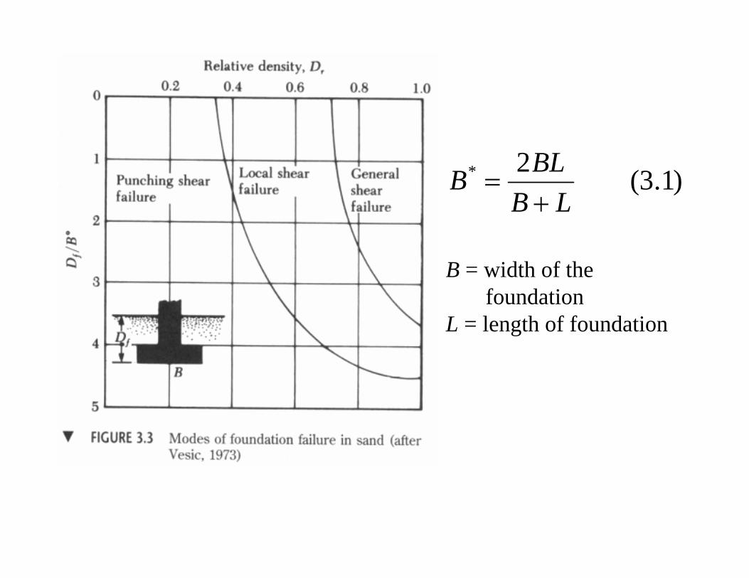
)1.3(2*
LBBLB+
=
B = width of the foundation
L = length of foundation
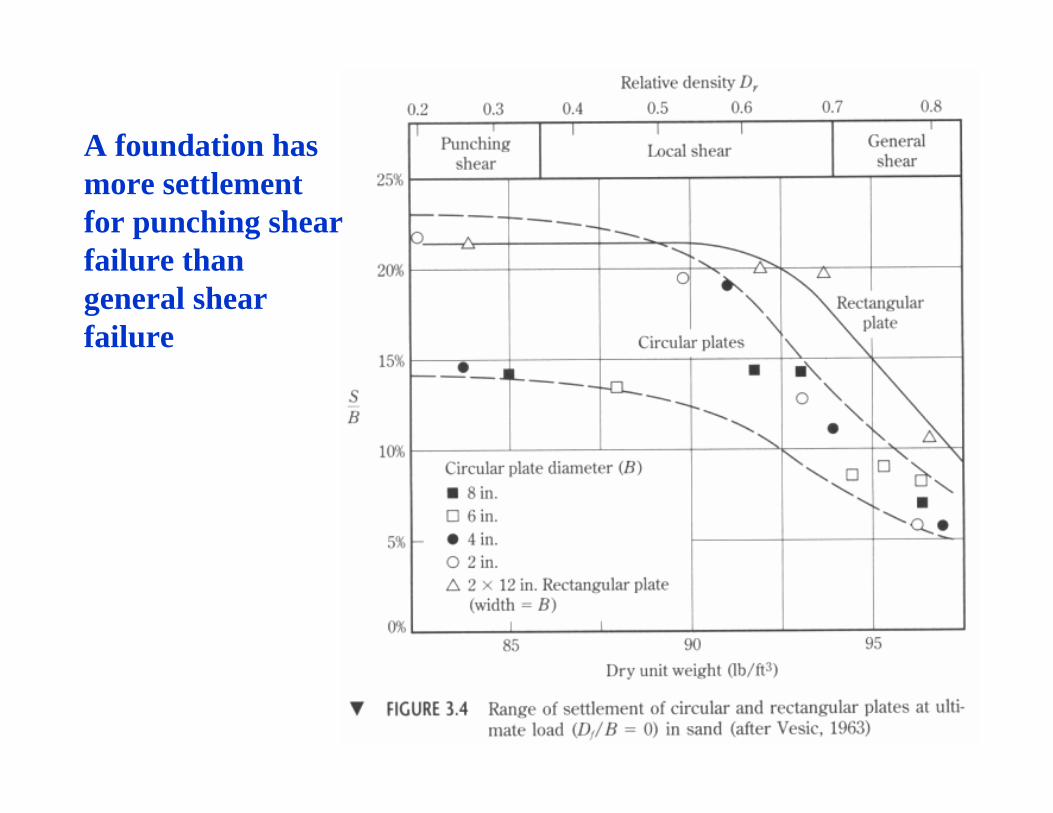
A foundation has more settlement for punching shear failure than general shear failure
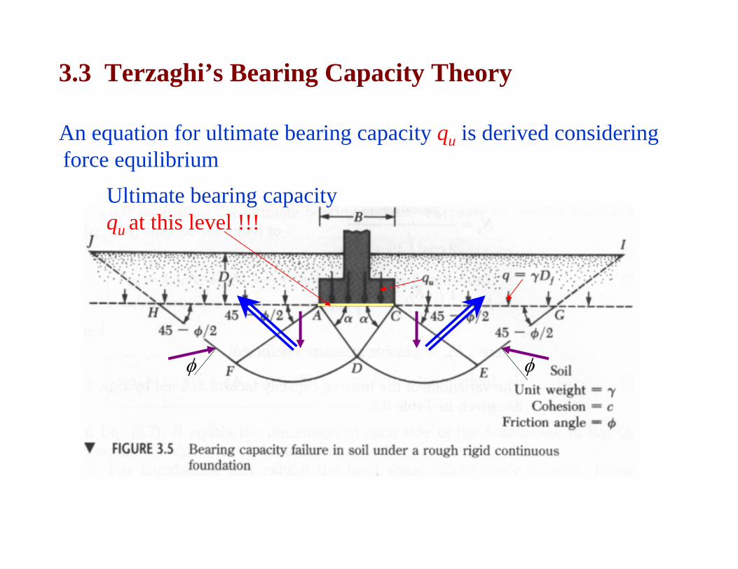
3.3 Terzaghi’s Bearing Capacity Theory
An equation for ultimate bearing capacity qu is derived considering force equilibrium
φφ
Ultimate bearing capacity qu at this level !!!
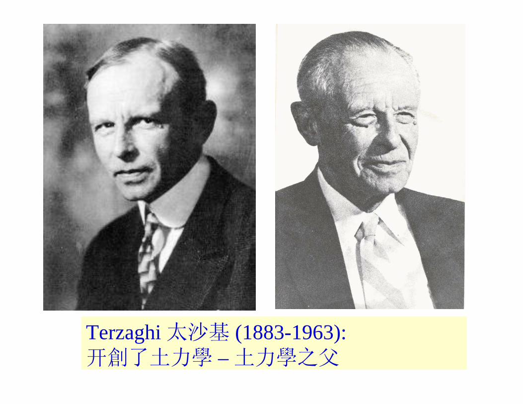
Terzaghi 太沙基 (1883-1963): 开創了土力學 – 土力學之父
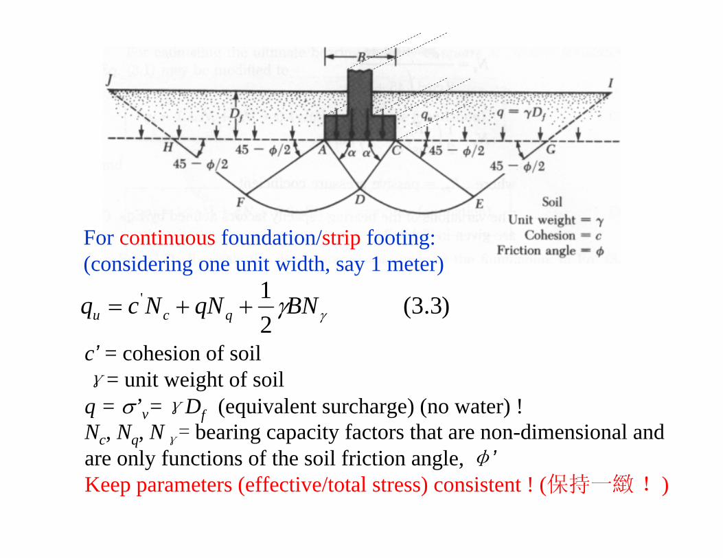
)3.3(21'
γγBNqNNcq qcu ++=
c’ = cohesion of soilγ= unit weight of soilq = σ’v=γDf (equivalent surcharge) (no water) !Nc, Nq, Nγ= bearing capacity factors that are non-dimensional and are only functions of the soil friction angle, φ’Keep parameters (effective/total stress) consistent ! (保持一緻!)
For continuous foundation/strip footing:(considering one unit width, say 1 meter)
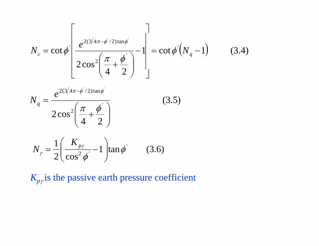
( ) )4.3(1cot1
24cos2
cot ''
2
tan)2/43(2'
''
−=
⎥⎥⎥⎥
⎦
⎤
⎢⎢⎢⎢
⎣
⎡
−
⎟⎟⎠
⎞⎜⎜⎝
⎛+
=−
qc NeN φφπ
φφφπ
)6.3(tan1cos2
1 ''2 φ
φγ
γ ⎟⎟⎠
⎞⎜⎜⎝
⎛−= pK
N
)5.3(
24cos2
'2
tan)2/43(2 ''
⎟⎟⎠
⎞⎜⎜⎝
⎛+
=−
φπ
φφπeNq
Kpγ is the passive earth pressure coefficient

γγBNqNcNq qcu 4.03.1 ++= (square foundation) (3.7)
γγBNqNcNq qcu 3.03.1 ++= (circular foundation) (3.8)
'''
21
32
γγBNqNcNq qcu ++= (strip foundation) (3.9)
''' 4.0867.0 γγBNqNcNq qcu ++= (square foundation) (3.10)
''' 3.0867.0 γγBNqNcNq qcu ++= (circular foundation) (3.11)
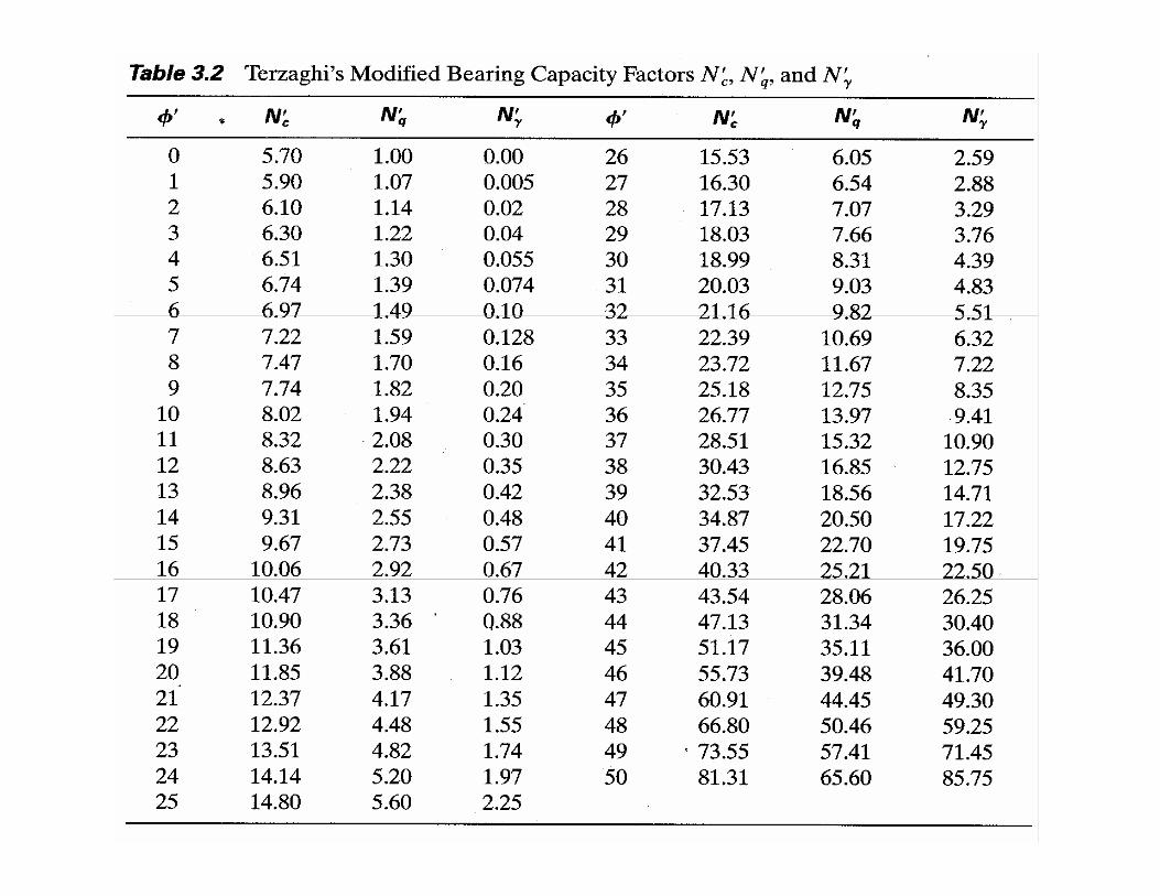
For local shear failure - Use reduced (2/3) friction angle:
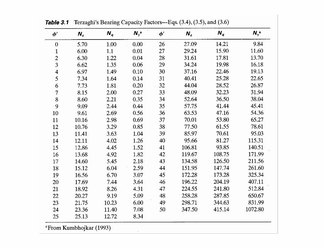
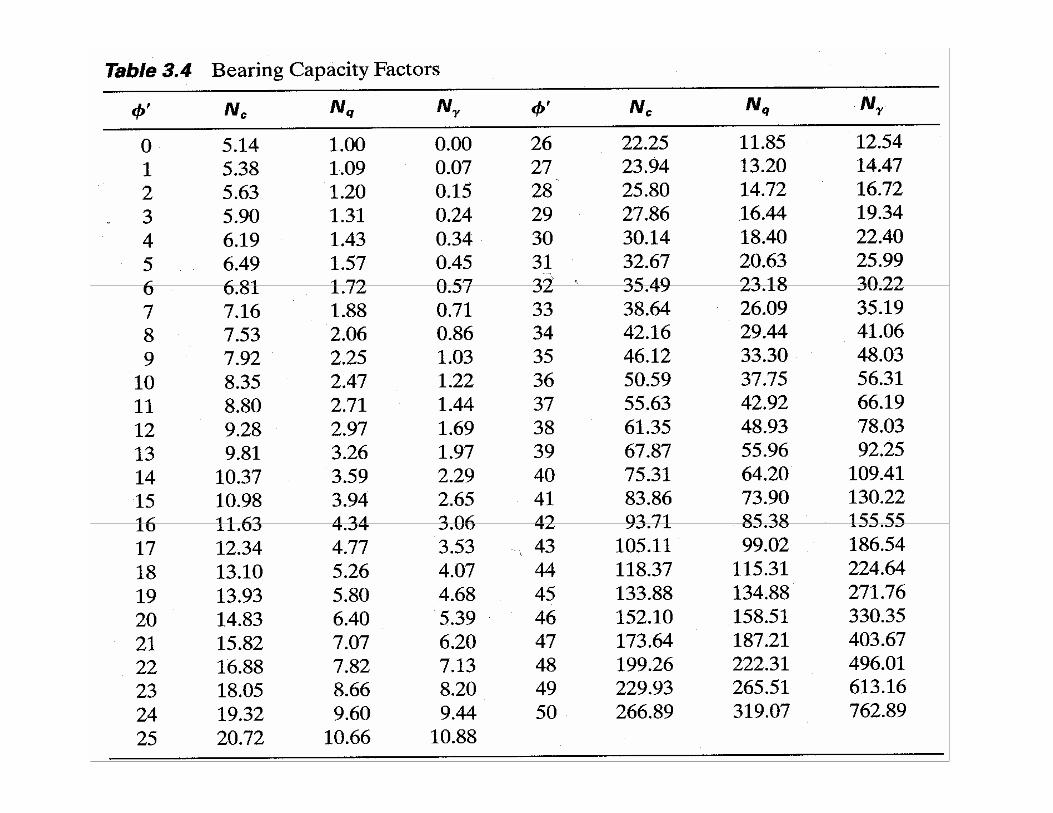
.2.3)'(tanusing,, 321'''' TableorcalculatedareNNN qc φφγ
−=
Terzaghi’s Bearing Capacity Theory Limitations:• No corrections on depth, load inclination, general foundation shape• Nγ is over-estimated.

3.4 Factor of Safety
Factor of Safety (FS) is defined in two ways:(a) Using gross ultimate bearing capacity qu:
)12.3(
)12.3(
bq
qFS
qqoraFSqq
design
u
alldesignu
all
=
≤=
The qall is gross allowable bearing capacity and qdesign is the design or current pressure on the foundation.
(3.12a) is for qall.(3.12b) is for assessment of the safety of the foundation!
FS is in the range 3 ~ 6

Factor of Safety (FS) is defined in two ways:(b) Using net (净) ultimate bearing capacity qnet(u):
fvdesignnetdesign
netdesign
u
netallnetdesignuunet
netall
uunet
Dqqqq
bq
qqFS
qqoraFS
qqFS
qqq
γσ ==−=
−=
≤−
==
−=
;
)15.3(
)15.3(
)14.3(
)(
)(
)()()(
)(
)(
The qall(net) is net allowable bearing capacity and qdesign(net) is the net design or net current pressure/stress on the foundation.
(3.15a) is for qall(net).(3.15b) is for assessment of the safety of the foundation!Keep “net” consistent ! (保持一緻!)
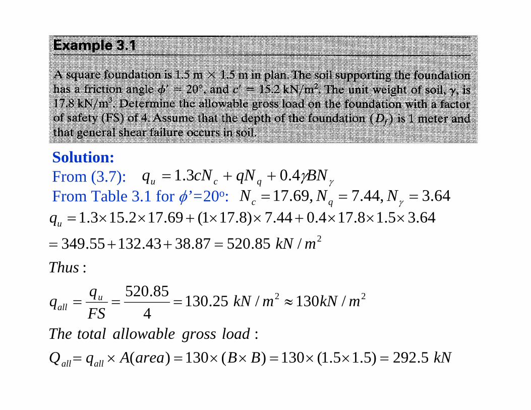
Solution:From (3.7):From Table 3.1 for φ’=20o:
γγBNqNcNq qcu 4.03.1 ++=64.3,44.7,69.17 === γNNN qc
kNBBareaAqQloadgrossallowabletotalThe
mkNmkNFSqq
ThusmkN
q
allall
uall
u
5.292)5.15.1(130)(130)(:
/130/25.1304
85.520:
/85.52087.3843.13255.349
64.35.18.174.044.7)8.171(69.172.153.1
22
2
=××=××=×=
≈===
=++=
×××+××+××=

Example 3.2Repeat Example 3.1, assuming that local shear failure occurs in the soil supporting the foundations.
Solution:From (3.10):From Table 3.2 for φ’=20o:
kNBBareaAqQloadgrossallowabletotalThe
mkNFSqq
ThusmkN
q
allall
uall
u
4.133)5.15.1(3.59)(3.59)(:
/3.594
3.237:
/3.2370.121.692.156
12.15.18.174.088.3)8.171(85.112.15867.0
2
2
=××=××=×=
===
=++=
×××+××+××=
''' 4.0867.0 γγBNqNcNq qcu ++=12.1,88.3,85.11 ''' === γNNN qc

3.5 Modification of Bearing Capacity Equations for Water Table
Keep effective parameters consistent ! (保持一緻)
γsat = saturated unitweight of soil
γw = unit weight ofwater;
fDD ≤≤ 10
)( '' γγγγ −+=Bd
Case 1:
γγ BNqNNcq qcu''
21
++=
)16.3(
)('
21
21'
γγ
γγγσ
DD
DDq wsatv
+=
−+== 1D
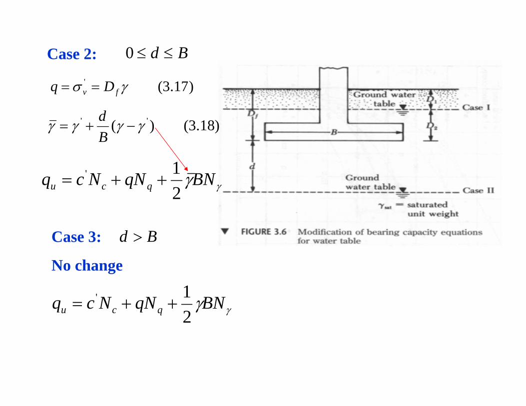
Bd ≤≤0Case 2:
γγBNqNNcq qcu 21' ++=
)17.3(' γσ fv Dq ==
)18.3()( '' γγγγ −+=Bd
Bd >Case 3:
No change
γγBNqNNcq qcu 21' ++=

3.6 The General Bearing Capacity Equation (重要!)
Keep effective/total parameters consistent ! (保持一緻)
)19.3(21
idsqiqdqsqcicdcscu FFFBNFFFqNFFFcNq γγγγγ++=
c= c’ (effective) or c (total) cohesionγ = γ’ (effective), (average) or total unit weight γ of the soilB =width of foundation (=diameter of a circular foundation);
factorsninclinatioloadFFF
factorsdepthFFF
factorsshapeFFF
iqici
dqdcd
sqscs
=
=
=
γ
γ
γ
,,
,,
,,
γ

)22.3(tan)1(2)21.3(cot)1(
)20.3()2
45(tan tan2
φ
φ
φ
γ
φπ
+=
−=
+=
q
qc
q
NNNN
eN
(3.23) by Prandt; (1921), (3.22) by Reissner (1924), (3.24) by Caquot and Kerisel (1953), Vesis (1973). More equations for Nγ.
For effective stress parameters using φ’ and c’;
Total stress parameters using φ and c.
Keep consistent !
The three bearing capacity factors are calculated using the following 3 equations or Table 3.4:

Shape Factors: (by De Beer 1970)
widthBlengthfoundationLLBF
LBF
NN
LBF
s
qs
c
qcs
=>=
−=
+=
+=
)25.3(4.01
)24.3(tan1
)23.3(1
γ
φ
Depth Factors: (by Hansen 1970)
)28.3(1
)27.3()sin1(tan21
)26.3(4.01
1/
2
=
−+=
+=
≤
d
fqd
fcd
f
FB
DF
BD
F
BDFor
γ
φφ

Inclination Factors: (by Meyerhof 1963)
)!degree(tan
)31.3(1
)30.3(tan)sin1(tan21
)29.3(tan4.01
1/
1
12
1
notradiansinisB
DNoting
FB
DF
BD
F
BDFor
f
d
fqd
fcd
f
⎟⎟⎠
⎞⎜⎜⎝
⎛
=
⎟⎟⎠
⎞⎜⎜⎝
⎛−+=
⎟⎟⎠
⎞⎜⎜⎝
⎛+=
>
−
−
−
γ
φφ
verticalfromangleninclinatioload
F
FF
i
o
o
qici
=
⎟⎟⎠
⎞⎜⎜⎝
⎛−=
⎟⎟⎠
⎞⎜⎜⎝
⎛−==
βφβ
β
γ )33.3(1
)32.3(90
1
2
2
β

Solution:
4.22,4.18304.3
/6.12187.0
:)21.3(,0
'
2
21
'
==>=
=×==
+=∴=
>
γ
γγγγ
φ
σ
γ
NNforTableFrom
mkNq
FFFBNFFFqNqfromc
waternotablewaterofmentionNo
qo
v
idsqiqdqsqu
Q
11.0302011;605.0
90201
901
1;202.017.0)30sin1(30tan21)sin1(tan21
:1/
6.04.01;577.1577.0130tan1tan1
2222
22
=⎟⎠⎞
⎜⎝⎛ −=⎟⎟
⎠
⎞⎜⎜⎝
⎛−==⎟⎟
⎠
⎞⎜⎜⎝
⎛−=⎟⎟
⎠
⎞⎜⎜⎝
⎛−=
=+=−+=−+=
≤
=−==+=+=+=
φββ
φφ
φ
γ
γ
γ
io
o
o
o
qi
df
qd
f
sqs
FF
FBBB
DF
BDAssumeLBF
BB
LBF
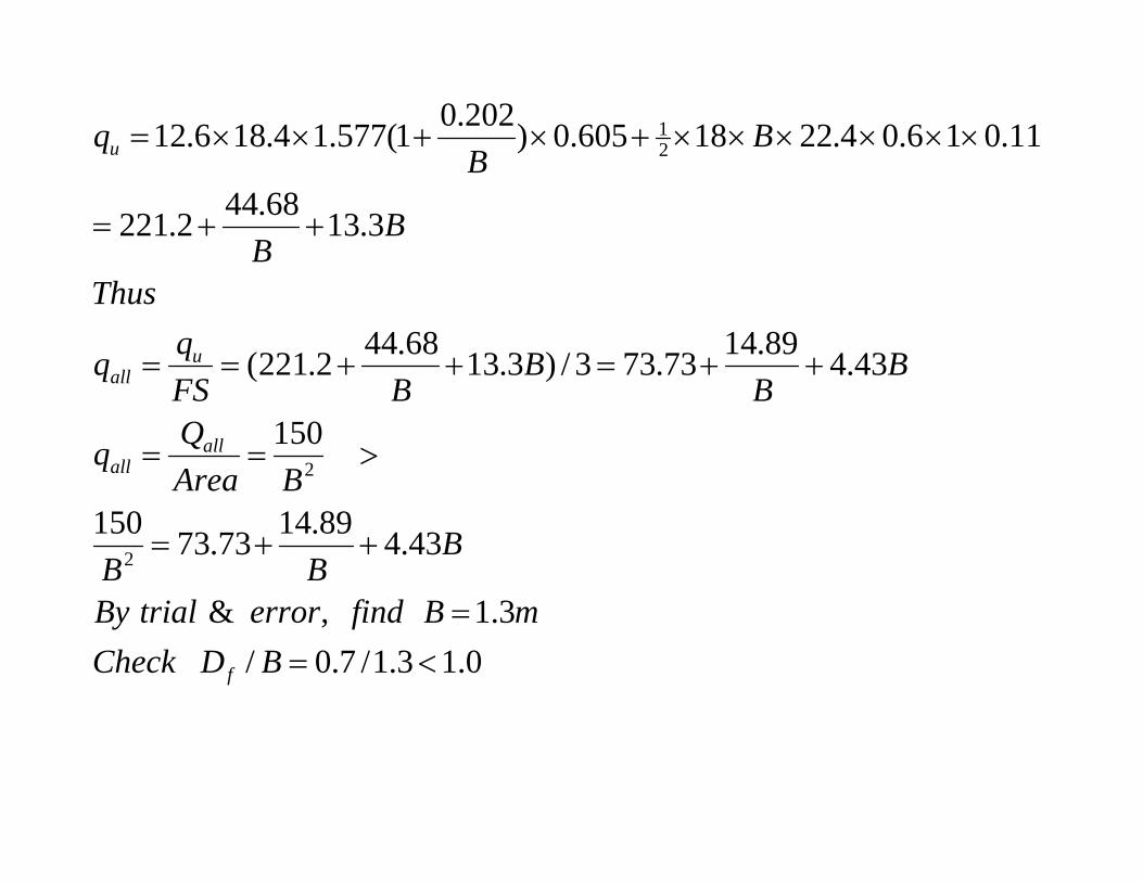
0.13.1/7.0/3.1,&
43.489.1473.73150
150
43.489.1473.733/)3.1368.442.221(
3.1368.442.221
11.016.04.2218605.0)202.01(577.14.186.12
2
2
21
<==
++=
>==
++=++==
++=
××××××+×+××=
BDCheckmBfinderrortrialBy
BBB
BAreaQq
BB
BBFS
Thus
BB
BB
q
f
allall
uall
u
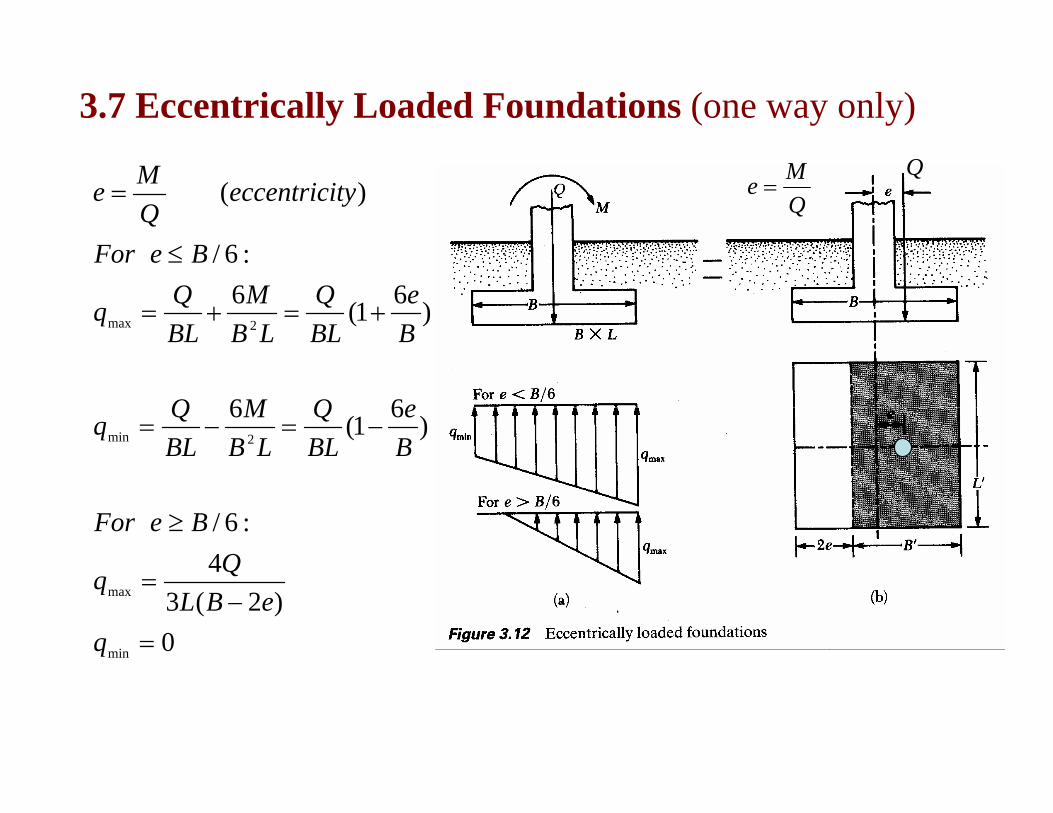
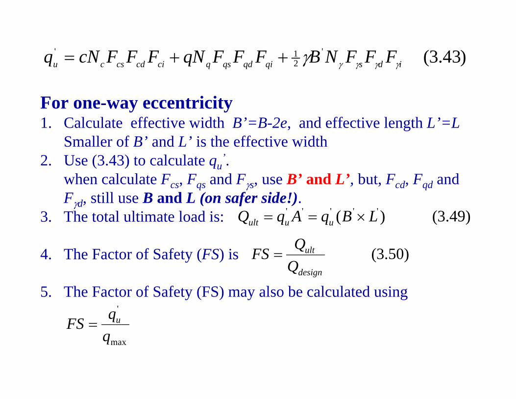
3.7 Eccentrically Loaded Foundations (one way only)
0)2(3
4:6/
)61(6
)61(6:6/
)(
min
max
2min
2max
=−
=
≥
−=−=
+=+=
≤
=
qeBL
BeFor
Be
BLQ
LBM
BLQq
Be
BLQ
LBM
BLQq
BeFor
tyeccentriciQMe Q
Me =Q

Calculation of foundation base pressure for e<=B/6:
LBMpMBBLp iiii 2)()(
6;223
222
1=⇒=××××
)61()61(62)()( B
eBLQ
BQM
BLQ
LBM
BLQppp iii ±=±=±=±=
Q
H
e=
Q
H
M= +
QMe = )(i )(ii
BLQp i =)(
)(ip )(iip)(iip
6;0)61(min
BeBe
BLQp =⇒=−= Valid for e<=B/6 only
H H
Q

Calculation of foundation base pressure for e>B/6:
)&(21
max"
Qasmaglocationsamethe
QLqBF
FforceverticalispressuretheofareatotalThe
v
v
==
Q
vF"B
"
31
2BBe −=
"
31 B
)2(34
)323(
22
323,
31
2
"max
""
eBLQ
LeB
QLB
eBBBBe
−=
−==∴
−=∴−=Q
)43.3('21'
idsqiqdqsqcicdcscu FFFNBFFFqNFFFcNq γγγγγ++=
For one-way eccentricity1. Calculate effective width B’=B-2e, and effective length L’=L
Smaller of B’ and L’ is the effective width2. Use (3.43) to calculate qu
’. when calculate Fcs, Fqs and Fγs, use B’ and L’, but, Fcd, Fqd and Fγd, still use B and L (on safer side!).
3. The total ultimate load is:
4. The Factor of Safety (FS) is
5. The Factor of Safety (FS) may also be calculated using
)49.3()( ''''' LBqAqQ uuult ×==
)50.3(design
ult
QQFS =
max
'
qqFS u=

)43.3('21'
idsqiqdqsqcicdcscu FFFNBFFFqNFFFcNq γγγγγ++=
For one-way eccentricityWhy B’=B-2e?
Qe
eB 2−
eB−
2eB−
2
B


Settlement of Shallow Foundation3.9 Types of Foundation Settlement3.10 Elastic Settlement Based on the Theory of
Elasticity3.11 Elastic Settlement of Foundations on Saturated
Clay3.13 Range of Material Parameters for Computing
Elastic Settlement
Lecture 2: Shallow Foundations(Chapter 3-Das)淺基礎
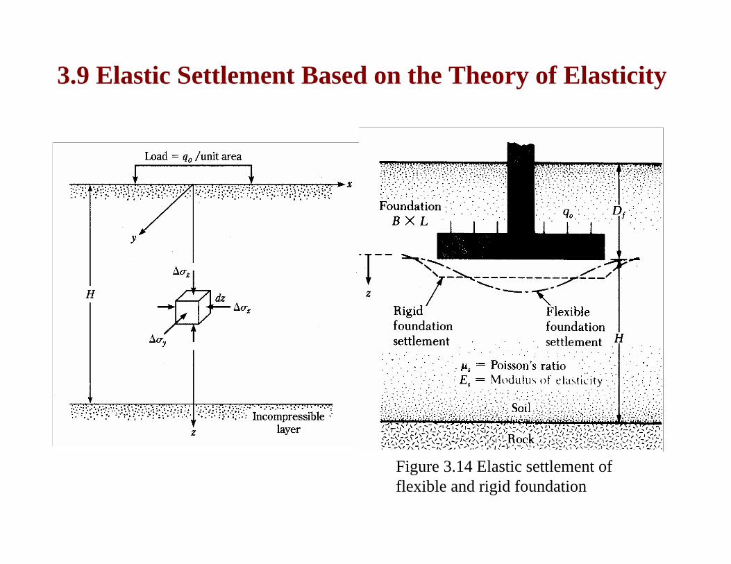
3.9 Elastic Settlement Based on the Theory of Elasticity
Figure 3.14 Elastic settlement of flexible and rigid foundation

""""2/
?)5(40:''
1)(
'
'
2'
corneratsettlementforBBfoundationofcenteratsettlementforBB
BBzsoilofmodulussYoungAverageEsoilofratiosPoisson
pressureappliednetq
IIE
BqS
s
s
o
fss
soe
=
=
<<===
−=
μ
μα
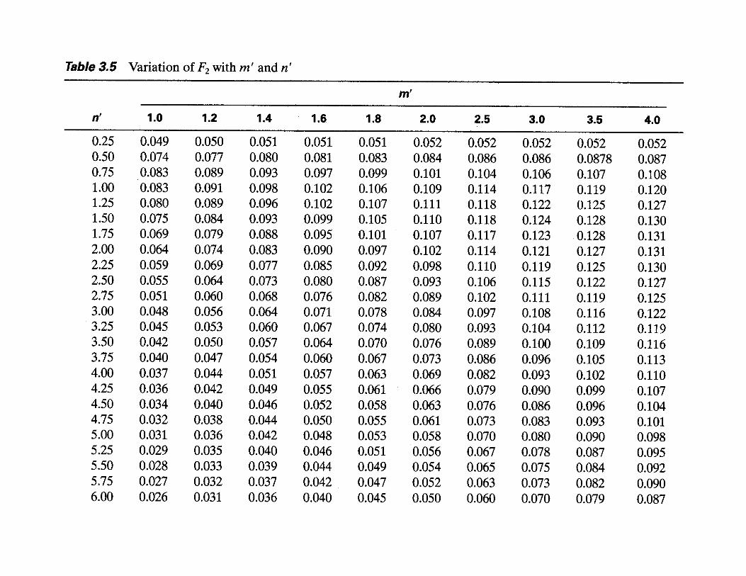
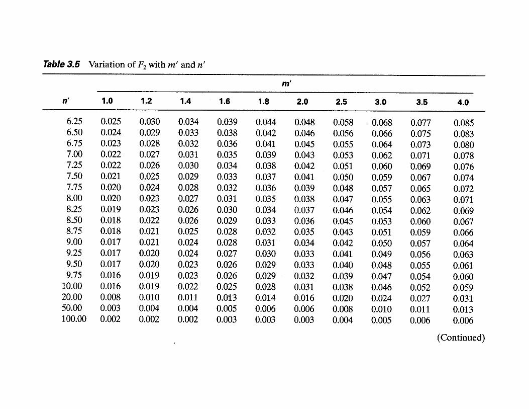
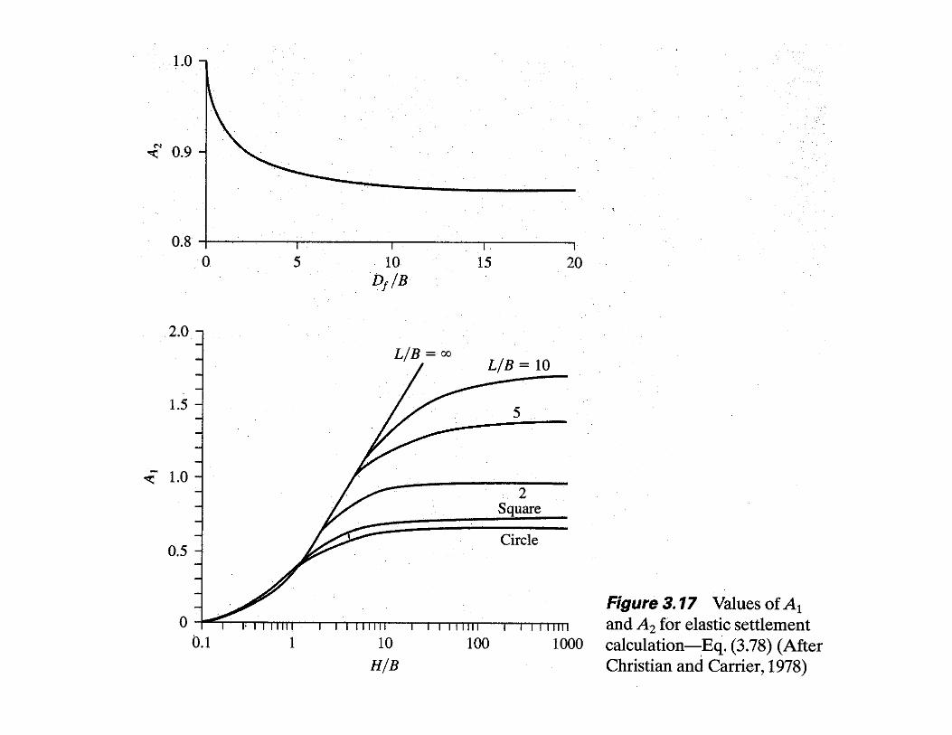
Use Tables 3.4 and 3.5 to find Is and If
If foundation is perfectly flexible, the settlement is calculated as follows (from Bowles 1987):
),()( 93.0 centerflexibleerigide SS =

BHn
BLm
cornerAtBHn
BLm
centerAtsettlementforfoundationoflocationondependingfactora
===
===
=
''
''
,,1
:"")2/(
,,4
:"":
α
α
α
)(5
)()(
smallerwhicheverBorHz
averagez
zEE is
s
=
Δ= ∑

1
11)1(ln
)11()11(ln
)()(tan2
)(11
21)1934,(
2'2''
'
2
2'2''
2'2''
1
2'2''
2'2'2''
21
'
2
11
21
++=
+++
+++=
+++
+++=
=
+=
−−
+=
=
−
nmnmA
nmmnmmA
nmmnmmmA
radianinAnF
AAF
FF
erSteinbrennfactorshapeI
o
o
s
s
s
π
π
μμ


tableorfigurefromIFind
casesallinIDifNoting
BL
BD
f
FoxfactordepthI
f
ff
sf
f
1,0
),,(
)1948,(
==
=
=
μ

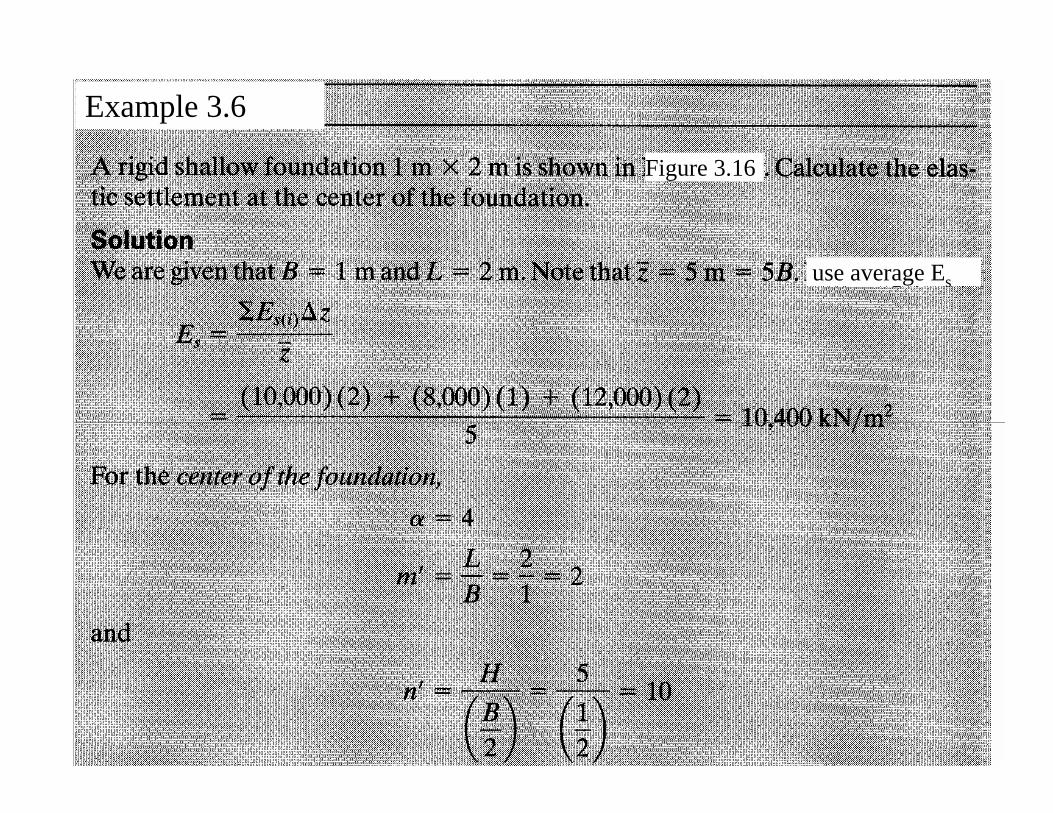
Example 3.6
Figure 3.16
use average Es
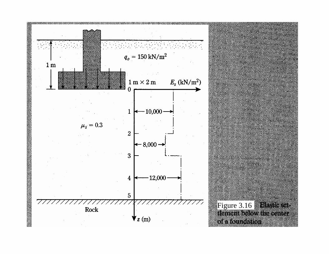
Figure 3.16

659.0031.0031
3.021641.0
121
21
=−
×−+=
−−
+= FFIs
ss μ
μ
659.0 mmm 2.120122.0 =
mmmm 39.112.12 =
Table 3.4 Eq. (3.69)
Figure 3.15

3.11 Elastic Settlement of Foundations on SaturatedClay
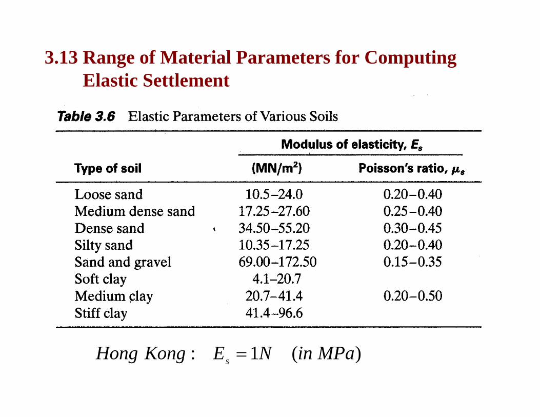
3.13 Range of Material Parameters for Computing Elastic Settlement
)(1: MPainNEKongHong s =

)(8.0 MPainNEs =

Primary Consolidation Settlement and Creep Settlement3.14 Primary Consolidation Settlement Relationships 3.15 Three-Dimensional Effect on Primary
Consolidation Settlement3.16 Vertical Stress Increase in a Soil Mass Caused by
Foundation Load (for Consolidation Settlement Calculation)
3.17 Allowable Bearing Pressure in Sand Based on Settlement Consideration
3.18 Field Load Test3.19 Presumptive Bearing Capacity3.20 Tolerable Settlement of Buildings
Lecture 2: Shallow Foundations(Chapter 3-Das)淺基礎

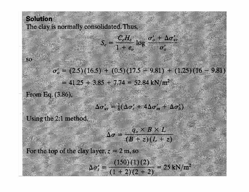
314 Primary Consolidation Settlement Relationships(One-Dimensional Straining – Vertical Compression Only)
'''
''''
'''
'
constant
0)(
)(21
)4(61
),,,,()(
)(;
1
mbt
bmtav
scoczz
zvz
o
oz
cz
ifH
zpc
CCfb
ma
einitialeratiovoideeestrainvertical
HdzSz
c
σσσ
σσσσ
σσσε
σε
ε
εεε
Δ≈Δ+Δ
≈Δ+Δ+Δ=Δ
=
Δ=
==
+Δ−
==
===
∫
'tσΔ
'mσΔ
'bσΔ
cHClay layer
conditionoedometerinsettlementS oedc −−

stresseffectiveverticialinitial
pressuredationpreconsoli
indexelasticswellingCC
indexncompressioCwhere
He
CHe
CS
withiiiAreasclayedconsolidatoverFor
He
CS
withiAreaclayedconsolidatoverFor
He
CHS
withiiAreaclayedconsolidatnormallyFor
o
c
es
c
cc
avcc
cspc
avco
cavs
pc
cav
cavc
czpc
cav
=
=
==
=
Δ++
++
=
Δ+<<
+−−
Δ++
=
<Δ+
−−
Δ++
==
≥Δ+
−
'
'
'
''0
0'0
'
0)(
''0
''
'0
''0
0)(
'''0
'0
''0
0)(
'''0
/
log1
log1
:)()(
log1
:)(
log1
:)(
σ
σ
σσσ
σσ
σσσσ
σσσ
σσσ
σσσε
σσσ
e'''zoz σσσ Δ+=
'cσ'
oσ'zσΔ
cC
es CorC
'zσ
)(i)(ii
conditionoedometerinsettlementS oedc −−

3.15 Three-Dimensional Effect on Primary Consolidation Settlement
22.3FigurefromratiosettlementK
conditionoedometerinsettlementS
KSS
oedc
oedcc
=
−=
−
−

22.3FigurefromratiosettlementKconditionoedometerinsettlementS
KSS
oedc
oedcc
=−
=
−
−

Stress due to a Concentrated LoadBoussinesg (1885) equation is
22
2/522 12
3:
yxrwhere
zrz
PincreasestressVertical
+=
⎥⎥⎦
⎤
⎢⎢⎣
⎡⎟⎠⎞
⎜⎝⎛+
=Δ
π
σ
3.16 Vertical Stress Increase in a Soil Mass Caused by Foundation Load (for Consolidation Settlement Calculation)

⎪⎪⎪
⎭
⎪⎪⎪
⎬
⎫
⎪⎪⎪
⎩
⎪⎪⎪
⎨
⎧
⎥⎥⎦
⎤
⎢⎢⎣
⎡⎟⎠⎞
⎜⎝⎛+
−=Δ 2/320
21
11
:
zB
q
centrebelowincreasestressVertical
σ
Stress due to a Circularly Loaded Area

Stress below a Rectangular Area
8.3
,
n)f(m,factorinfluence)(2
)(3:
00 0 2/5222
30
TableUsezLn
zBm
I
Iqzyxzdxdyq
cornerthebelowincreasestressverticalThe
L
y
B
x
==
==
=++
=Δ ∫ ∫= = πσ

Table 3.8 Variation of Influence Value I

Table 3.8 Variation of Influence Value I
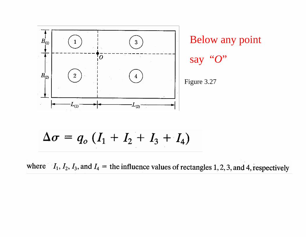
Below any point
say “O”
Figure 3.27
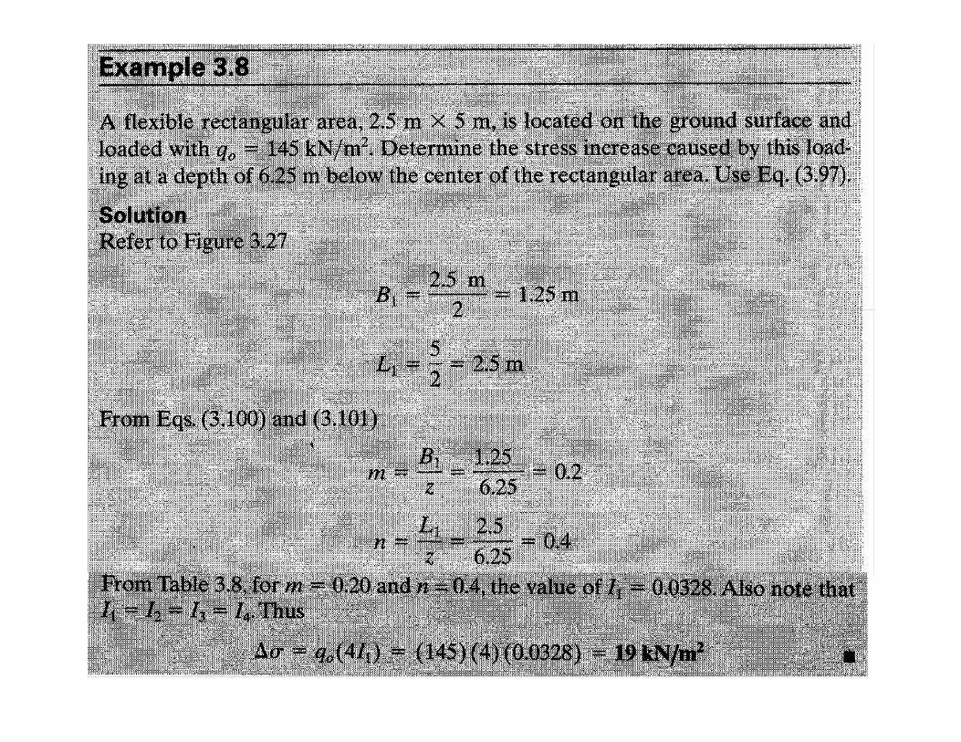
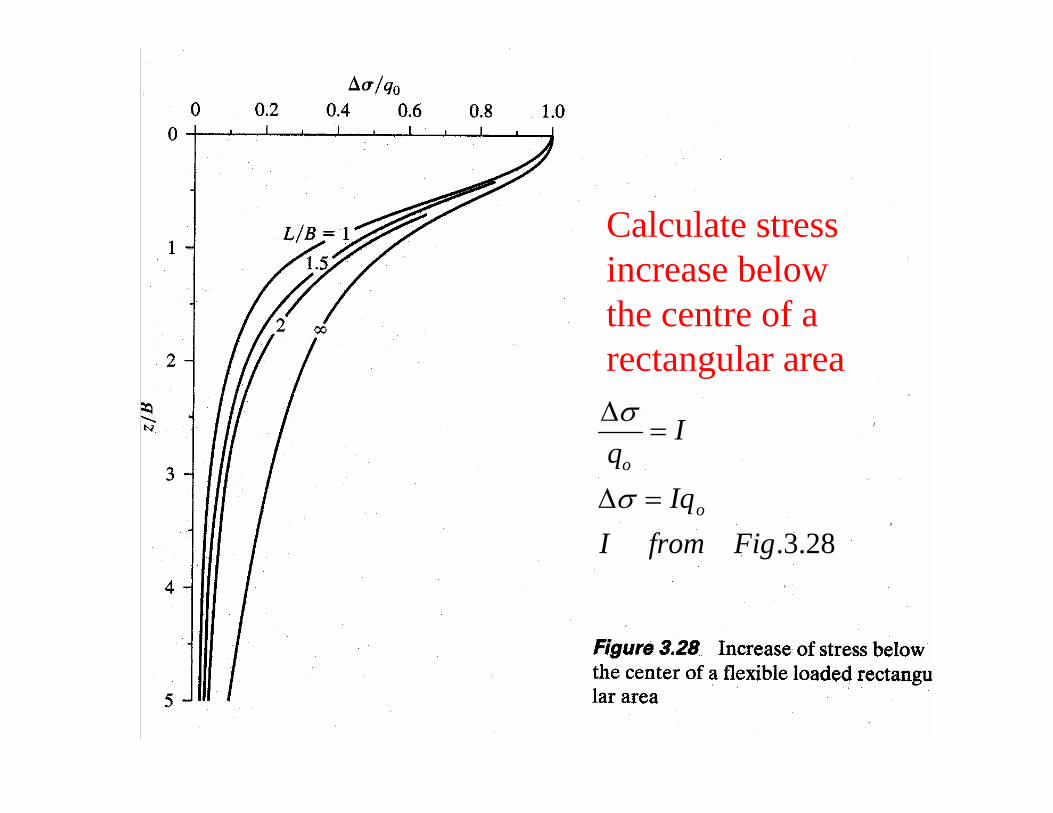
Calculate stress increase below the centre of a rectangular area
28.3.FigfromIIq
Iq
o
o
=Δ
=Δ
σ
σ

cCoe


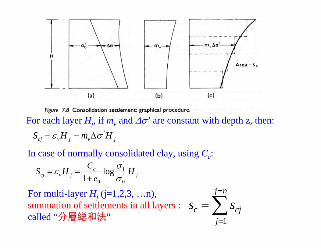
For each layer Hj, if mv and Δσ’ are constant with depth z, then:
jvjvcj HmHS 'σε Δ==
In case of normally consolidated clay, using Cc:
jc
jvcj He
CHS '0
'1
0
log1 σ
σε+
==
For multi-layer Hj (j=1,2,3, …n), summation of settlements in all layers :called “分層縂和法”
∑=
=
=nj
jcjc ss
1
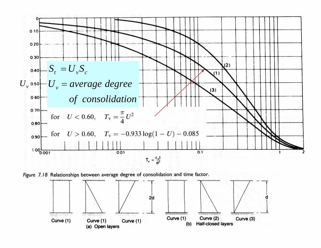
vU
ionconsolidatofdegreeaverageU
SUS
v
cvt
==
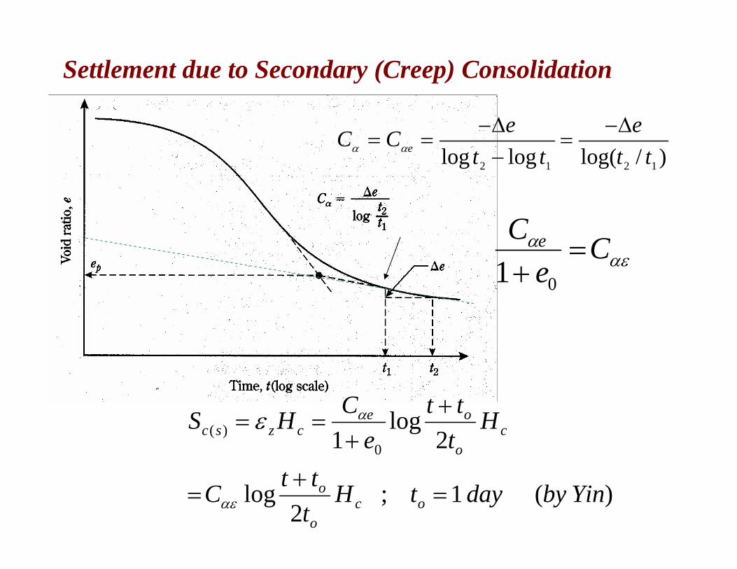
Settlement due to Secondary (Creep) Consolidation
)(1;2
log
2log
1 0)(
YinbydaytHtttC
Httt
eCHS
oco
o
co
oeczsc
=+
=
++
==
αε
αε
)/log(loglog 1212 tte
tteCC e
Δ−=
−Δ−
== αα
αεα Ce
C e =+ 01
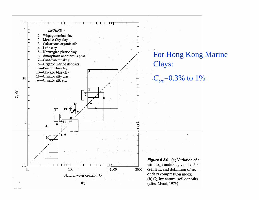
For Hong Kong Marine Clays:
Cαe=0.3% to 1%

Why a clayey soil creeps?
Creep is due to –viscous adsorbed water (double layers) on clay particles–viscous re-arrangement/sliding/deformation of clay particles/plates–viscous deformation of clay plates
Adsorbed water is NOT free water which is free to flow under gravity.
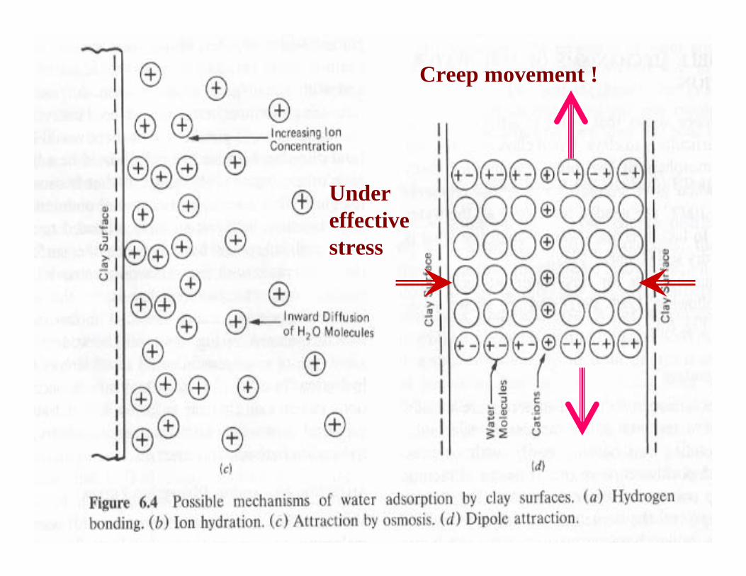
Under effective stress
Creep movement !

• Creep always exists under the action of effective stresses (loading), independent of the excess pore water (or pore pressure).
• Therefore, creep has nothing to do with the“primary”consolidation.
• And creep exists during and after “primary”consolidation.
• Creep rate depends on stress/strain state:–Creep rate is large in a normally consolidated state.–Creep rate is small in a over-consolidated state.

Bjerrum’s time line model, apparent “pre-consolidation pressure”, ageing and “delayed compression” (Bjerrum 1967)

3.17 Allowable Bearing Pressure in Sand Based on Settlement ConsiderationMeyerhof (1956) proposed a correlation for the net allowable bearing pressure for foundation with SPT (N1)60 allowable settlement 25mm:
)22.1)((28.3
128.399.7)/(
)22.1)((98.11)/(2
602
)(
602
)(
)(
mmBforB
BNmkNq
mmeterinBforNmkNq
Dqq
allnet
allnet
fallallnet
>⎟⎠⎞
⎜⎝⎛ +
=
≤=
−= γ
Meyerhof and his wife in Newfoundland 1993 在加拿大:地基和桩基Photo was taken by JH Yin 1993 at an offshore platform construction site

3.17 Allowable Bearing Pressure in Sand Based on Settlement ConsiderationFor allowable settlement > 25mm (by Bowles 1977):
mminsettlementtolerableS
BDfactordepthF
mBforSFB
BNmkNq
mminBforSFNmkNq
e
fd
edallnet
edallnet
=
≤+==
>⎟⎠⎞
⎜⎝⎛ +
=
≤=
33.1)/(33.01
)22.1()25
(28.3
128.398.11)/(
)22.1)(()25
(16.19)/(
2
602
)(
602
)(
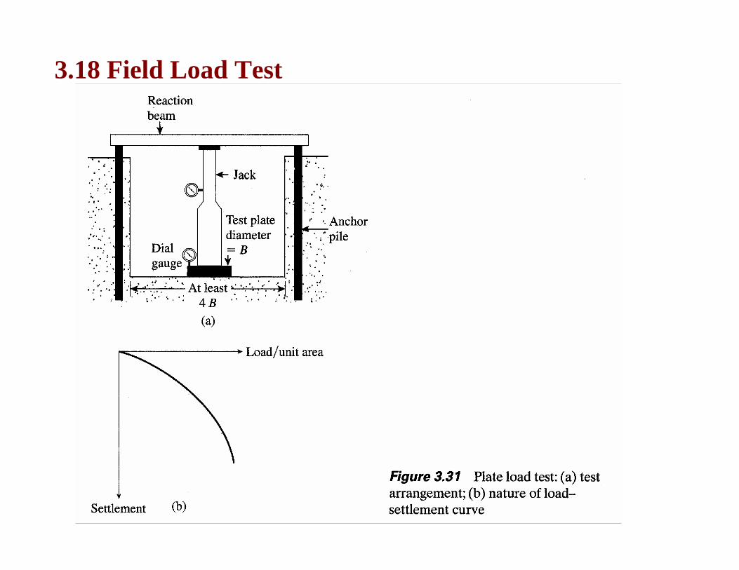
3.18 Field Load Test

platetestofcapacitybearingultimateqfundationproposedofcapacitybearingultimateq
whereqq
clayintestsFor
Pu
Fu
PuFu
=
=
=
)(
)(
)()(
:
platetestofwidthBfundationproposedofwidthB
whereBBqq
soilssandyintestsFor
P
F
P
FPuFu
==
= )()(
:

3.20 Tolerable Settlement of Buildings
ratiodeflectionL
EAlinereferencefromdeflectionrelative
lij
=Δ
−
=Δ
Δ==
=
)(
)jandipoints
betweendistanceis(
lS
distortionangular
pointssuccesibetwobetweengradient
''
ij
T(ij)β
α
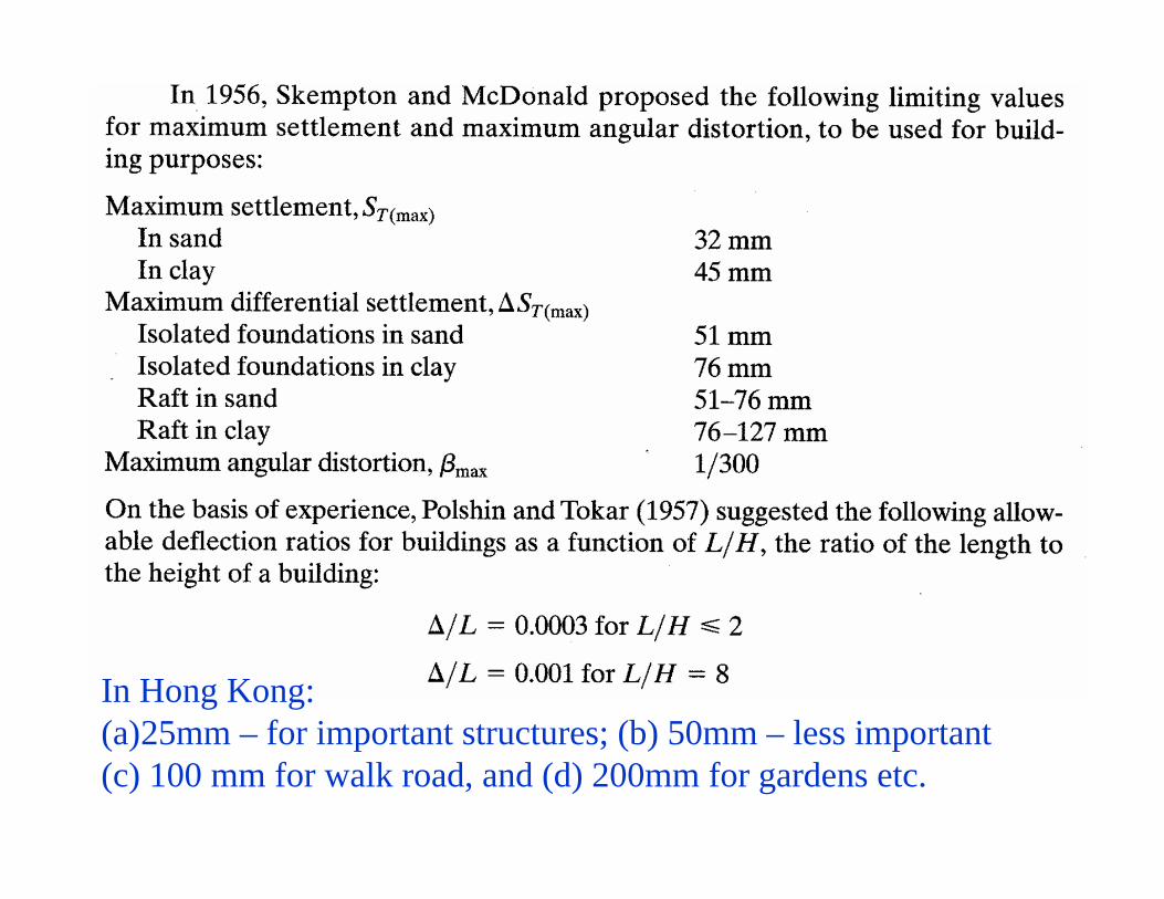
In Hong Kong:(a)25mm – for important structures; (b) 50mm – less important(c) 100 mm for walk road, and (d) 200mm for gardens etc.
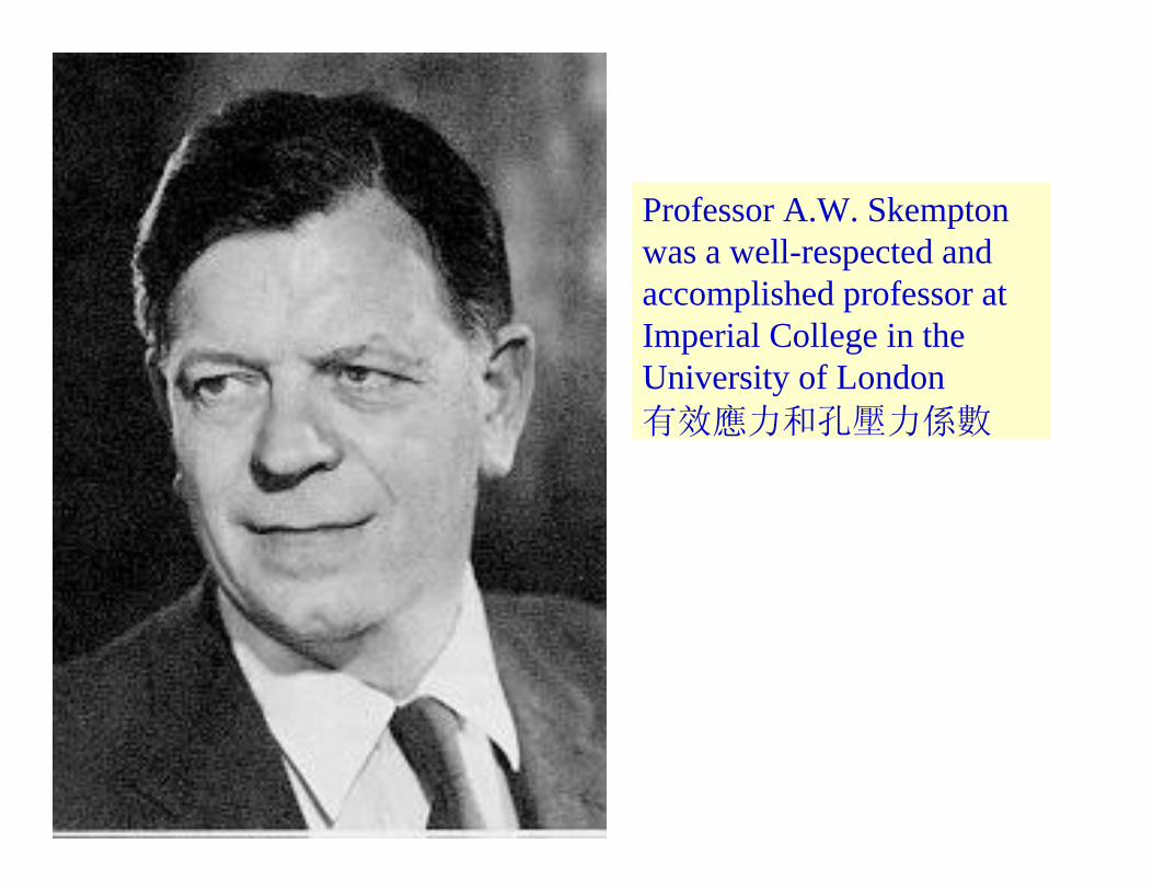
Professor A.W. Skemptonwas a well-respected and accomplished professor at Imperial College in the University of London有效應力和孔壓力係數

Problems:


For Figure 3.14, go to see Section 3.9 Elastic Settlement Based on the Theory of Elasticity
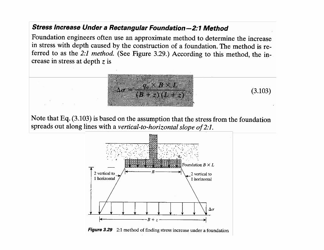
For Figure 3.27, go Section 3.16: Stress below a Rectangular Area


