Download - SPECIFYING AND SIZING THE BATTERY CHARGER

Page 1 of 16
SPECIFYING AND SIZING THE BATTERY CHARGER
Section 15.1 through 15.6 will give a semi-technical description of operation of the SCR,
Magnetic Amplifier, and Ferro resonant Control Chargers; Section 15.7 will discuss charger
sizing; 15.8 discusses various charger options; and 15.9 provides a typical charger
specification.
15.1 Theory of Diode Operation
The diode is a single junction, two-layer semiconductor. Conventional diode symbols are
shown below:
The diode exhibits the following circuit characteristics:
(a) Current can flow from the anode to the cathode when the voltage exceeds
approximately 0.5 volts with the proper polarity (plus to minus).
(b) No appreciable current can flow from the cathode to the anode, regardless of
the voltage magnitude, as long as the diode reverse voltage rating is not
exceeded. Note: When the diode reverse voltage rating is exceeded, the
reverse current flow will usually destroy the device.
Characteristics (a) and (b) are illustrated below.

Page 2 of 16
15.2 Theory of SCR Operation
The SCR is a three-junction, four-layer semiconductor. Conventional SCR symbols are
shown below.
The SCR exhibits the following circuit characteristics:
(a) Current can flow from the anode to the cathode, when the voltage across the
device exceeds approximately one volt plus to minus, and the gate lead is
made positive with respect to the cathode by a suitable gate signal.
(b) No appreciable current can flow from the cathode to the anode regardless of
the voltage magnitude as long as the junction breakdown voltage is not
exceeded. Note: When this voltage is exceeded, the reverse current flow
through the SCR will usually destroy the device.

Page 3 of 16
(c) Unlike the diode, the SCR can block current flow in the forward direction
(anode to cathode) by keeping the gate lead negative with respect to the
cathode.
Characteristics (a), (b) and (c) are illustrated below.
Once the SCR is switched “on”, three things must happen before the device recovers its
forward blocking (open switch) characteristic:
(a) The positive gate to cathode voltage must be removed.
(b) The forward current flow must be stopped.
(c) Items (a) and (b) must be maintained for a sufficient time for the junction
carriers to recombine or deionize. This recovery period is called the SCR
“turnoff time” or SCR “commutating time”.
15.3 Switching AC with SCR’s
The SCR is a highly-efficient method of converting fixed frequency alternating current into an
adjustable voltage direct current.
The diagram below indicates how this is done.

Page 4 of 16
(a) With no gate signal applied, the SCR blocks both forward and reverse current
flow and no voltage appears across the load (R1).
(b) When a proper signal is applied to the SCR gate, the device is turned on during
the rest of the positive half cycle of source voltage and direct current flows
through the load.
(c) By advancing or delaying (phasing) the application of the gate signal during
each positive half cycle of source voltage, the effective voltage across the load
can be adjusted up or down. Therefore, the effective current in the circuit can
be varied by phase controlling the firing of the SCR.
It should be noted that during the negative half of each cycle, the forward current flow
through the SCR goes to zero and the SCR is “commutated” in readiness for the next
positive half cycle and its accompanying gate signal.
Note: The commutating time for commercial grade SCR’s is in the order of 10 to 80
microseconds. Since the negative half cycle of a 60 Hz AC source is over 8000
microseconds long, there is an ample time for SCR commutation. This means the SCR
commutation is called “natural” or “line commutation”
Below is a typical hybrid (SCR & diode) bridge, with an explanation of how it works.

Page 5 of 16
(a) During the positive half cycle of source voltage, current flows into the anode of
SCR1 (when the gate signal is applied) through SCR1, and load (R1),
continuing through D2 and back to the source.
(b) During the negative half cycle of source voltage, negative current flows into the
cathode of D1, through D1, R1, SCR2 (when it is gated) and back to the
source.
15.4 General Operation of Phase Controlled SCR Chargers
The charger’s output voltage and, therefore, its charge rate, is determined by the control
circuit and its effect on the moment in time during each half cycle of source AC power when
the rectifier SCRs are fired (gated).
A voltage sensing circuit monitors the charger’s output DC voltage. This voltage is
constantly compared with a desired reference voltage. Any resulting error signal is fed to a
phase shift circuit, which triggers the gate drive pulses to advance or retard the firing of the
SCRs in the rectifier bridge.
A current sensing circuit develops a signal which is proportional to the AC input current,
which in turn is proportional to the DC output current. An increase in output current above
the charger’s current limit setting will cause the current limit signal to override the error signal
produced in the voltage control comparator and thus control the phase shift of the SCR gate
signals. This limits the output current to its pre-set value to provide short circuit capability at
the output terminals.

Page 6 of 16
Typical SCR Charger Schematic
15.5 General Operation of Magnetic Amplifier Chargers
The charger’s output voltage, and therefore its charge rate, is determined by the DC voltage
control circuit and its effect on the saturable reactor.
A zener diode is used to compare the charger output voltage with the desired output voltage.
When the battery is discharged, and the charger output voltage is low, the reactor saturating
coil saturates the reactor resulting in a reduced reactor impedance, and therefore more
voltage is applied to the primary of the input transformer. This, of course, results in an
increased voltage on the transformer secondary, and therefore a higher DC output voltage
from the diode bridge.
As the battery voltage increases, the zener diode begins to conduct into the base of the
control transformer, thus shunting the current from the saturating coil of the reactor. The
reactor begins to desaturate, increasing the impedance, and thus reducing the voltage on the
primary of the input transformer.
A saturating current resistor limits the charger output current to a preset amount by limiting
the saturating current to the reactor. Although the output currents typically available from
magnetic amplifier charger designs may appear to be high, they are usually produced only
after the output voltage has dropped well below any usable system output voltage.

Page 7 of 16
Typical Magnetic Amplifier Charger Schematic
15.6 General Operation of Ferroresonant Controlled Battery Chargers
The loosely coupled power secondary (S1), resonant secondary (S2), and resonant capacitor
(C1) resembles a typical ferroresonant transformer. The addition of the saturable inductor
(SR) and Triac (T) provide a method of discharging the capacitor (C1) before saturation of
the core occurs. Turning on the Triac at a predetermined time in each half-cycle causes a
pseudosaturation which has the effect of core saturation in a conventional ferroresonant
transformer, but allows the output voltage to be controlled externally, thus highly regulated
against line, load, and frequency variations.
Output voltage regulation is achieved by comparing a portion of the output voltage to a
temperature compensated reference represented by zener diode (2). Any “error” or
difference between these two voltages is amplified by an operational amplifier (OP1) and its
output is used to control the charging time of capacitor (C2). (C2) charging time determines
the firing time of the injunction transistor (U) and Triac (T).
An increase in output voltage causes a higher voltage to appear at the output of (OP1). This
higher charging voltage causes (C2) to charge at a higher rate, resulting in the unijunction
and triac firing sooner in the cycle, thus reducing the output voltage to near its original value.
Low noise characteristics are achieved because only low values of control current are being
switched instead of the total load current, as in phase controlled SCR circuits. (High power
factors, current limiting, high efficiency, and suppression of line transients are inherent
features of the controlled ferroresonant regulator.)
Page 8 of 16
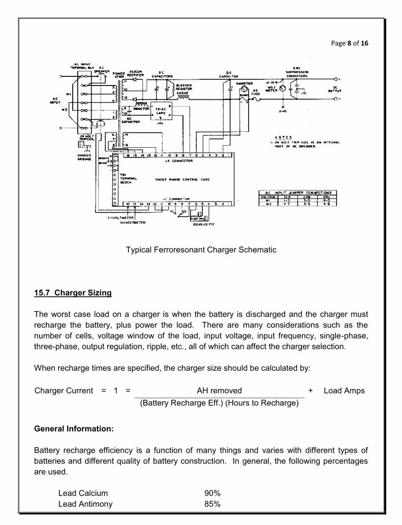
Typical Ferroresonant Charger Schematic
15.7 Charger Sizing
The worst case load on a charger is when the battery is discharged and the charger must
recharge the battery, plus power the load. There are many considerations such as the
number of cells, voltage window of the load, input voltage, input frequency, single-phase,
three-phase, output regulation, ripple, etc., all of which can affect the charger selection.
When recharge times are specified, the charger size should be calculated by:
Charger Current = 1 = AH removed + Load Amps
(Battery Recharge Eff.) (Hours to Recharge)
General Information:
Battery recharge efficiency is a function of many things and varies with different types of
batteries and different quality of battery construction. In general, the following percentages
are used.
Lead Calcium 90%
Lead Antimony 85%

Page 9 of 16
Nickel Cadmium 70%
It should be understood that battery recharge time actually relates to two different
parameters of the charger:
1. The current capacity of the charger
2. The voltage setting of the charger
Percent Charge vs. Time
T1 is almost completely determined by the current capacity, but the charger’s current
capacity has almost no effect on T2.
T2 is almost completely determined by the output voltage setting of the charger,
although this setting has virtually no effect on T1.
The charger will be in its current limit mode during the first part of T1, and as the battery
voltage begins to increase, the charger will come out of current limit. T1 can be cut in half
simply by doubling the current capacity of the charger.
The only way to shorten T2 is to shift up to a higher charging curve by applying more v/c to
the battery. This is done by adjusting the “recharge” mode (“equalize” for lead systems) of
the charger output up to a higher voltage.
Caution: This may not be as simple as it first appears. There are various potential problems
which must be considered:
1. Lead acid batteries are very sensitive to high charging voltages. The extra heat
build-up in the plates may cause plate warpage.
2. The voltage window of the applied load may not accommodate the increase in

Page 10 of 16
charger voltage.
The charger can be adjusted up to 1.65 to 1.7 v/c for pocket plate nickel cadmium cells
without any damage to the battery, but all loads have some maximum voltage above which
serious damage will result. One of the following two standard methods is commonly used to
effect desired recharge times without damage to the load.
Method 1 (Oversizing) -
Since T1 is a function of the current capacity of the charger, but only restores the
battery to 75% to 80% of full charge, the battery can be oversized by 25% and a larger
charger used. Even though the battery will not be fully recharged during time period
T1, it will be recharged sufficiently to carry another duty cycle for the specified time
period.
Note: when specifying the system, it may be desirable to require “a charger which will
restore the battery sufficiently to carry another duty cycle as specified for the battery” instead of fully recharged” in a given period of time.
Method 2 (Dropping Diode) (CEMF) -
An option on the charger is used many times to allow a higher voltage across the
battery than that imposed across the load. This option is commonly called a
“Counter EMF Cell” or a “Dropping Diode Circuit”.
Dropping Diode Circuit
With approximately 0.8 v/diode drop across each diode junction, the total battery is
seeing 2.4 more volts than the load. If the AC line fails and the battery is left to supply
the load, the shorting relay (contractor for large loads) is de-energized and shorts out
the diode circuit. Caution must be exercised in configuring this system. If a high
current load is applied to the battery system faster than the contractor can react, the
power will be drawn through the diodes for a fraction of a second. The diodes, as well

Page 11 of 16
as the contractor, would therefore need to be capable of carrying this load.
Both methods described, oversizing and dropping diodes, are commonly used and very
reliable.
For the example battery sized in Section 14, the charger would be sized as follows:
Note: An 1100 AH battery was selected but only 607 AH were removed,
therefore, only 607 AH needs to be replaced during recharge.
Use 60A Charger
(Note) For calculating feeder circuits, the worst case battery charger input currents
are actually much higher than may be expected. The incorrect method, which
is many times used and which results in under sizing the feeder circuits, is to
assume a 90% efficiency for the 24 VDC, 60 ADC charger and calculate the
feeders as follows:
WRONG
The value is incorrect for several reasons. First, although the unit is a 24 VDC, 60 ACD unit,
it can be adjusted up to 32 VDC output and it provides 110% current limit at full voltage.
Also, the charger is about 92% efficient when powering a resistive load. But when operating
into a discharged battery, its efficiency drops to 75% (12 and 24 VC units), 85% (120 and
240 VDC units). Probably the greatest effect on input current is a result of power factor. The
unit has a .8 pf when operating into a resistive load, but it drops to about is .5 when operating
into a discharged battery.
Also, the utility is within specification at 120 VAC + 5% - 10%.
Therefore the actual worst case charger input current is:
Correct
607 AH
(.9)(24)+ 25 = 53.11 Charge =
AH Removed+ 1 Load =
(Regharge Eff.) (Hours to Recharge)
1 Input = (24 VDC) 60 ACD)
= 13.3 ARMS(120 VAC) (.9)

Page 12 of 16
Typical power factor and efficiencies for various charger types are:
15.8 Charger Features and Options
Ripple
All chargers have some magnitude of AC ripple on their DC output. This primarily comes
from the AC line and must be filtered to a desired level by the filter circuit on the output of the
charger.
Our industrial chargers have 2% ripple, standard, with a 30 mv optional filter offered.
This means the 24 VDC charger sized above would have (32 volts maximum) (.02) = .64
VRMS ripple riding on top of the DC output. This charger could be ordered with a 30 mv filter
option and then the output RMS ripple would be cut to .030 VRMS.
All of this sounds very basic, but here is the point which all charger manufacturers assume,
and yet the industry has been careless about communicating to the specifics and users:
Because the battery also helps filter the charger output, much like a large capacitor, all filter
designs are made assuming not only that a battery is connected across the charger output
terminals, but that the magnitude of battery AH capacity is at least four times the magnitude
of charger current capacity.
For Advertised Ripple
Battery AH capacity = 4 (charger | capacity). If the charger is larger in proportion to the
battery than this, there will be more ripple on the charger output than is typically advertised.
Note: Even for chargers designed to function independently of a battery as “Battery
Eliminators”, it is still true that their ripple will increase when the battery is
1 (RMS) = 32 VDC (60 ADC) (1.1)
= 52.1 ARMS(108 VAC) (.75) (.5)
Charger Type
pf Ef
1Ø SCR 0.5 0.75
3Ø SCR 0.6 0.75
Controlled Ferro 0.85 0.85
Magnetic Amplifier 0.5 0.65
Worst Case

Page 13 of 16
removed.
If for any reason an application is going to use a large charger in proportion to the battery,
specify this in the invitation to bid. We at SEI and, it is supposed, all of our competitors, can
supply special filters to reduce the ripple to any level desired under any condition specified.
The filter may be more expensive and larger, and in some instances it may require a larger
charger cabinet, but it can certainly be provided.
Additional Options and Features
The main consideration in dealing with battery chargers is to be sure the desired features are
specified.
Input and output circuit breakers are very convenient, but are typically more expensive than
fuses. Fuses are certainly adequate as long as they can be replaced without having to
disconnect the electrical connections at the charger.
An output voltmeter and ammeter is an asset but should not be used for precise voltage
setting unless it has a usable scale accuracy of at least +0.1%.
The types of features which can make a major difference in both the cost and operational
satisfaction of the charger are:
Input: Circuit breakers or fuses
Output: Circuit breakers or fuses
Regulation:
Ripple:
Battery Elimination Feature:
Negative temperature compensation:
(Does it need to be remote? Is the battery in a different environment from
the charger?)
Paralleling:
Load Sharing:
Alarm Relays:
Lamp test switches:
Input Voltage:
Type of Equalize Circuit: (timer, switch etc.)
Wiring technique: (nothing, color coded, wire numbers)
Documentation: (block diagram, detailed electrical schematic, point to point wiring
diagram, blue prints, sepias, mylars, microfilm)
Alarm lamps and remote alarm relay contacts can be a real service in monitoring the system.

Page 14 of 16
The functions that are more likely to be desired for remote monitoring are:
AC Input Failure
Charger Failure
Low Battery Voltage
High Battery Voltage
Individual Positive and Negative Ground Fault
Note: If the system DC voltage is greater than 70 VDC, ground fault alarms could be
lifesaving. If one side of the battery had been intentionally or accidentally
referenced to ground and a technician were to connect a wrench to the other
side of the battery, his body would become the fuse. DC is much more lethal
than AC. When working around high DC voltages, think of the DC as meaning
“Dangerous Current”.
Other functions which are less likely to be motorized, but from time to time may be, are:
Charger mode (float or recharge)
High Charger Temperature
Charger Door Ajar
Fan Failure (if forced cooling is used)
All batteries have a negative temperature coefficient. This means that to maintain proper
charge on the battery plates, the charger voltage should be decreased approximately 0.23%
per °C rise in battery temperature.
In some stationary applications, it is not uncommon to experience a wide range of ambient
temperature conditions. With a range of 0-110 °F, the charger voltage would need to be
adjusted +9 to -4.2%. Failure to make these adjustments will result in increased battery
maintenance and reduced battery life.
To use a non-temperature compensated battery charger in the above example, would affect
the battery the same as connecting a +1% regulated battery charger across the batteries in a
controlled temperature room and then raising the charger voltage 4.2% for half of the year
and reducing the charger voltage 9% for the other half. As you can imagine, this would
rapidly destroy the battery.
Note: If the battery is mounted in a different environment from the battery charger,
the temperature sensing devise must be remote mounted at the battery.
If a relatively large capacity battery is being charged from a very small capacity battery
charger (trickle charge), the plates of the battery will take on what is referred to as a “surface

Page 15 of 16
charge”. They will appear to be fully charged. However, because the charger is too small to
provide sufficient energy to force adequate electron flow homogeneously through the plates,
certain plates in the plate group will accept a surface charge allowing a current path around
their surface and through the electrolyte to the adjoining plate surface. Open circuit voltage
tests, low load voltage tests or hydrometer tests of a battery in this condition will probably not
reveal the problem; yet when high current loads are energized and attempt to draw large
currents, the voltage of the undercharged battery will drop and the load will shut down.
Almost all battery chargers have a current limit circuit which protects the charger from
destroying itself into a low impedance load (discharged battery). Attention should be given to
whether this current is available at full voltage or at a reduced voltage. Some chargers
advertise a rather high current limit capability, while in fact, they will produce that current only
at near zero volts. If the current limit capacity of the charger is going to have value, it must
be at a voltage sufficient to recharge the battery and power the load.
Most conventional battery chargers have DC voltage regulations of +1-2% and a DC voltage
ripple of 2-8%. Excessive voltage swings and high ripple cause extra heating inside the
battery. If maintenance free batteries are being used, battery life will be increased by as
much as 2-3 times by specifying:
Regulation: +1% line and load (maximum)
Ripple: 100 mv RMS maximum (with battery connected)
With maintenance free batteries, temperatures compensation is also much more important
than with conventional flooded batteries because of the inability to replenish lost water within
the cell.

Page 16 of 16


