Download - Smart Life Solutions

Central Control Module
EN
USER MANUAL
(CCMXX6X)
V1.0
Smart Life Solutions
Content
1: Important Safety Information
2: Description and Properties
3: Technical Properties
3.1: Technical Details
3.2: Technical Drawing
4: Installation
4.1: Before Installation
4.2: Mechanical and Electrical Assembly
4.2.1: Return to Factory Settings
4.2.2: Electrical Assembly
4.2.3: Mechanical Assembly
5: Button and Indicators
5.1: LED Indicators
5.2: Button Functions
6: Communication Properties
7: Commissioning
8: Regulations
3
4
4
4
5
5
5
6
6
6
7
8
8
9
9
10
11
1: Important Safety Informat�on
ELECTRIC SHOCK DANGER!
Do not open the product!
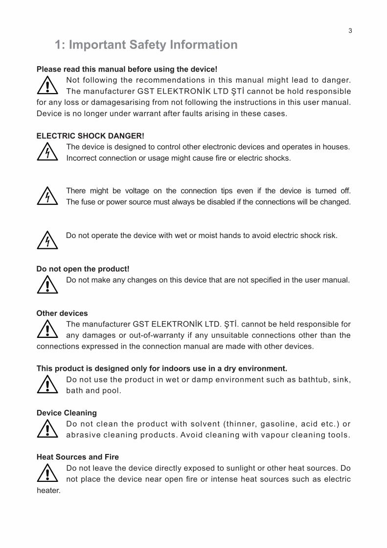
Please read th�s manual before us�ng the dev�ce!
Not follow�ng the recommendat�ons �n th�s manual m�ght lead to danger.
The manufacturer GST ELEKTRONİK LTD ŞTİ cannot be hold respons�ble
for any loss or damagesar�s�ng from not follow�ng the �nstruct�ons �n th�s user manual.
Dev�ce �s no longer under warrant after faults ar�s�ng �n these cases.
The dev�ce �s des�gned to control other electron�c dev�ces and operates �n houses.
Incorrect connect�on or usage m�ght cause fire or electr�c shocks.
There m�ght be voltage on the connect�on t�ps even �f the dev�ce �s turned off.
The fuse or power source must always be d�sabled �f the connect�ons w�ll be changed.
Do not operate the dev�ce w�th wet or mo�st hands to avo�d electr�c shock r�sk.
Do not make any changes on th�s dev�ce that are not spec�fied �n the user manual.
Do not leave the dev�ce d�rectly exposed to sunl�ght or other heat sources. Do
not place the dev�ce near open fire or �ntense heat sources such as electr�c
Other dev�ces
The manufacturer GST ELEKTRONİK LTD. ŞTİ. cannot be held respons�ble for
any damages or out-of-warranty �f any unsu�table connect�ons other than the
connect�ons expressed �n the connect�on manual are made w�th other dev�ces.
Th�s product �s des�gned only for �ndoors use �n a dry env�ronment.
Do not use the product �n wet or damp env�ronment such as bathtub, s�nk,
bath and pool.
Dev�ce Clean�ng
Heat Sources and F�re
Do not clean the product w�th solvent (th�nner, gasol�ne, ac�d etc.) or
abras�ve clean�ng products. Avo�d clean�ng w�th vapour clean�ng tools.
heater.
3

2: Descr�pt�on and Propert�es
3: Techn�cal Propert�es
3.1: Techn�cal Deta�ls
Central Control Module w�th �nohom 16 �nput/output �s used for manag�ng dev�ces
that can be operated w�th load open-close commands such as CCMXX6X alarm
control, room-based heat�ng, �llum�nat�on, plug, curta�n-bl�nds.
Power Consumpt�on 9.6W (Max)
Supply Voltage 12VDC
Outputs 8/16 Relay (277VAC 10/16A)
Inputs 8/16 AC/DC Insulated Input
RF 433 Mhz
�nohom OS
2.5mm² screwed electr�c term�nal
IP 20
0 - 50°C
Max 50°C %65 Amb�ent Hum�d�ty
Max 2000m
156mm x 90mm x 58mm
Rack Mount�ng
EN55032:2015, EN55024:2011, EN62368-1
Commun�cat�on
Operat�ng System
Connect�ons
Protect�on Class
Operat�ng Temperature
He�ght
Relat�ve Hum�d�ty
D�mens�ons
Installat�on
EMC Standards
4
CCM1760 8 bu�ld-�n 10A 250VAC and 8 bu�ld-�n 16A 277VAC (�nrush 100A) relay output and 16DC �nput.
CCM17618 bu�ld-�n 10A 250VAC and 8 bu�ld-�n 16A 277VAC (�nrush 100A) relay output and 16AC �nput.
CCM21608 bu�ld-�n 10A 250VAC (�nrush 40A) and 8 bu�ld-�n 16A 277VAC (�nrush 100A) relay output and 16 DC �nput.
CCMXX6Y Y=0 DC INPUT
Y=1 AC INPUT
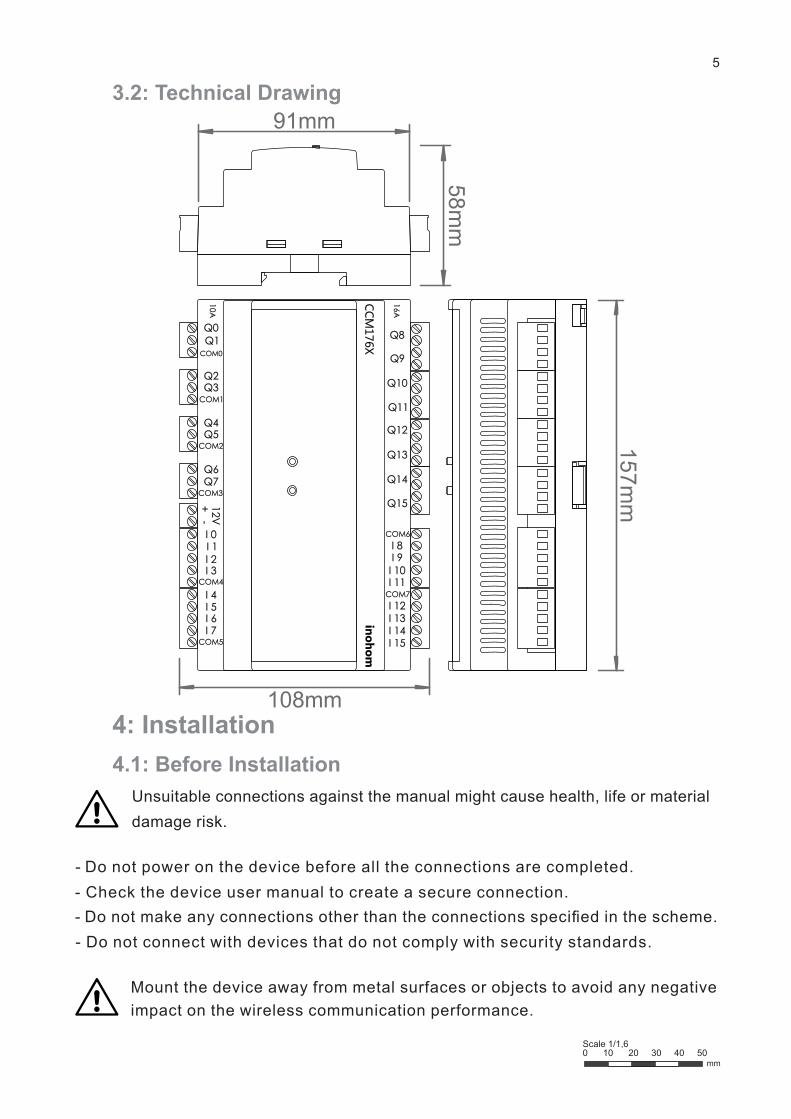
3.2: Techn�cal Draw�ng
4: Installat�on
4.1: Before Installat�on
Unsu�table connect�ons aga�nst the manual m�ght cause health, l�fe or mater�al
damage r�sk.
- Do not power on the dev�ce before all the connect�ons are completed. - Check the dev�ce user manual to create a secure connect�on.
- Do not make any connect�ons other than the connect�ons spec�fied �n the scheme.
- Do not connect w�th dev�ces that do not comply w�th secur�ty standards.
Mount the dev�ce away from metal surfaces or objects to avo�d any negat�ve
�mpact on the w�reless commun�cat�on performance.
5
inohom
CC
M176X
16
ACOM1
COM2
COM3
COM4
COM5
COM7
COM6
Q1Q0
Q6Q7
I 0I 1I 2I 3
I 4I 5I 6I 7
I 15I 14I 13I 12
I 11I 10I 9I 8
Q15
Q14
Q13
Q12
Q11
Q10
Q9
Q8
12V
+ -
Q5Q4
Q3Q2
COM0
10
A
108mm
58m
m
157m
m
mm0 10 20 30 40 50 Scale 1/1,6
91mm

4.2: Mechan�cal and Electr�cal Assembly 4.2.1: Return to Factory Sett�ngs
4.2.2: Electr�cal Assembly
When you press and hold these two buttons
and wa�t unt�l the LEDs no longer bl�nk,
the dev�ce w�ll return to factory sett�ngs.
S�nce some relays have a common COM connect�on when the relay �s
connected to the comb� bo�ler, leave Q1 output empty �f connected to Q0
and leave Q3 output empty �f connected to Q2. There �s no COM connect�on from
Q8 to Q15. Th�s can be used for d�rect connect�on.
6
inohomCCM1760
16A
CO
M1
CO
M2
CO
M3
CO
M4
CO
M5
CO
M7
CO
M6
Q1
Q0
Q6
Q7
I 0 I 1 I 2 I 3 I 4 I 5 I 6 I 7I 1
5I 1
4I 1
3I 1
2
I 11
I 10
I 9I 8Q15
Q14
Q13
Q12
Q11
Q10
Q9
Q8
12V+ -Q
5Q
4
Q3
Q2
CO
M0
10A
M
K
+ -12V
L
N
SIREN SENSOR
M
L
N
CCM1760 DC Input Connect�on Representat�on
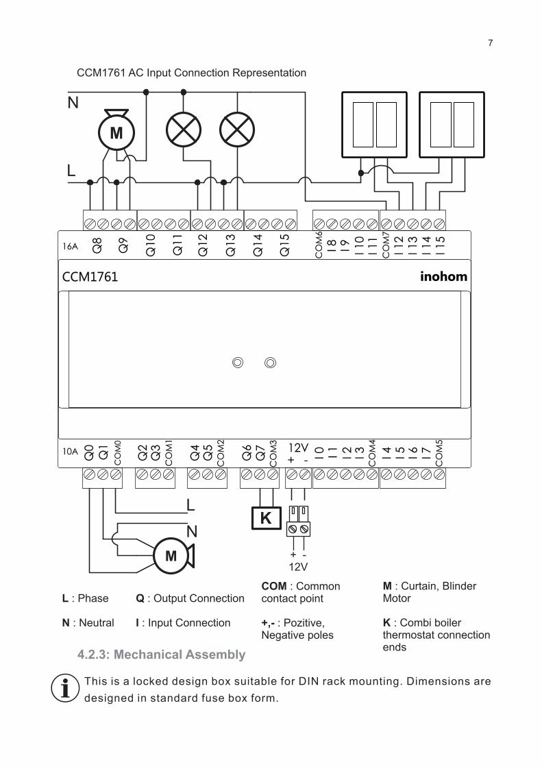
L : Phase
N : Neutral
COM : Common contact po�nt
+,- : Poz�t�ve,Negat�ve poles
Q : Output Connect�on
I : Input Connect�on
M : Curta�n, Bl�nder Motor
K : Comb� bo�ler thermostat connect�on ends
7
inohomCCM1761
16A
CO
M1
CO
M2
CO
M3
CO
M4
CO
M5
CO
M7
CO
M6
Q1
Q0
Q6
Q7
I 0 I 1 I 2 I 3 I 4 I 5 I 6 I 7I 1
5I 1
4I 1
3I 1
2
I 11
I 10
I 9I 8Q15
Q14
Q13
Q12
Q11
Q10
Q9
Q8
12V+ -Q
5Q
4
Q3
Q2
CO
M0
10A
M
M + -12V
L
L
N
N
K
CCM1761 AC Input Connect�on Representat�on
Th�s �s a locked des�gn box su�table for DIN rack mount�ng. D�mens�ons are
des�gned �n standard fuse box form.
4.2.3: Mechan�cal Assembly

8
1: Pull the mount�ng apparatus down.
2: Push the dev�ce to mount�ng bear�ng.
A: Ra�l mount�ng bear�ng
B: Screw mount�ng bear�ng
1
1
AA
A
A
A
B
B
B
2
5.1: LED Ind�cators
5: Buttons and Ind�cators
LEFT RIGHT
inohomCCM176X
16A
CO
M1
CO
M2
CO
M3
CO
M4
CO
M5
CO
M7
CO
M6
Q1
Q0
Q6
Q7
I 0 I 1 I 2 I 3 I 4 I 5 I 6 I 7I 1
5I 1
4I 1
3I 1
2
I 11
I 10
I 9I 8Q15
Q14
Q13
Q12
Q11
Q10
Q9
Q8
12V+ -Q
5Q
4
Q3
Q2
CO
M0
10A
PO
WE
R
ON
CO
MM
UN
ICA
TIO
N
I0I8 I9 I1
0
I11
I12
I13
I14
I15
I1 I2 I3 I4 I5 I6 I7
Q0
Q1
Q2
Q3
Q4
Q5
Q6
Q7
Q8
Q9
Q10
Q11
Q12
Q13
Q14
Q15

inohom
6: Commun�cat�on Propert�es
inohom
SMART TOUCHPANEL
SMART TOUCHPANEL MINI
WEB
RF 433 Mhz
inohomCCM176X
16A
CO
M1
CO
M2
CO
M3
CO
M4
CO
M5
CO
M7
CO
M6
Q1
Q0
Q6
Q7
I 0 I 1 I 2 I 3 I 4 I 5 I 6 I 7I 1
5I 1
4I 1
3I 1
2
I 11
I 10
I 9I 8Q1
5
Q1
4
Q1
3
Q1
2
Q1
1
Q1
0
Q9
Q8
12V+ -Q
5Q
4
Q3
Q2
CO
M0
10A
inohom
RL 1720
NOVA PANEL
MOBILE
CCMXX6X
The dev�ces use �nohom commun�cat�on protocol. CCMXX6X can w�relessly
commun�cate w�th other �nohom products and can learn and sw�tch output state
values of other products.
İnohom IP Gateway dev�ces (Nova Panel/Home Manager) enable manag�ng other
dev�ces �ntegrated to the automat�on v�a the �nternet by enabl�ng the system to
commun�cate on IP layer.
SWITCHOther dev�ces
�ntegrated v�a IPCamera, Intercom, EIO
inohom
9
D�fferent tasks can be ass�gned to �nohom Central Control Module �nput and
outputs. Funct�ons ass�gned to �nput and output are prov�ded by �nohom
5.2: Button Funct�ons
author�sed dealers. Th�s operat�on �s completed by tra�ned techn�cal personnel �n
�mplementat�on program.
When there �s power on the dev�ce, press and hold two buttons for 2 seconds for
the output control mode. The left button selects the output and the r�ght button
changes the state. You can ex�t th�s mode by press�ng and hold�ng two buttons for 2 seconds.
7: Comm�ss�on�ng
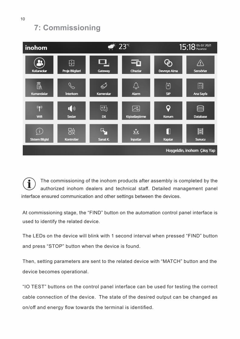
The comm�ss�on�ng of the �nohom products after assembly �s completed by the
author�zed �nohom dealers and techn�cal staff. Deta�led management panel
�nterface ensured commun�cat�on and other sett�ngs between the dev�ces.
At comm�ss�on�ng stage, the “FIND” button on the automat�on control panel �nterface �s
used to �dent�fy the related dev�ce.
The LEDs on the dev�ce w�ll bl�nk w�th 1 second �nterval when pressed “FIND” button
and press “STOP” button when the dev�ce �s found.
Then, sett�ng parameters are sent to the related dev�ce w�th “MATCH” button and the
dev�ce becomes operat�onal.
“IO TEST” buttons on the control panel �nterface can be used for test�ng the correct
cable connect�on of the dev�ce. The state of the des�red output can be changed as
on/off and energy flow towards the term�nal �s �dent�fied.
10

8: Regulat�ons
11
Legal Warn�ng
Declarat�on of Conform�ty
GST Elektron�k Elektr�k Yaz�l�m Mak�na Dan. San. Ve T�c. Ltd. St�.
Kemaloz Mah. Deg�rmendere Cad. No:8/A 64100 Usak/Turkey
www.�nohom.com
0090 850 811 82 83
�nfo@�nohom.com
The propert�es, funct�onal�t�es and other product propert�es can be changed w�thout pr�or
not�ce. �nohom reserves the r�ght to rev�ew or update the products, software or documents
w�thout any l�ab�l�ty to not�fy any �nd�v�duals or organ�zat�ons. İnohom �s a trademark of
GST Elektron�k Elektr�k Yazılım Mak�na Dan. San. ve T�c. Ltd. Şt�. All other brand and
product names here�n are the trademarks of the�r respect�ve owners.
The domest�c product�on logo on all the products show
that themanufactur�ng and software are 100% completed
�n Turkey.
The company has ISO 9001 Qual�ty Management, 14001
Env�ronment Management, 45001 Occupat�onal Health
and Safety Standards.
The dev�ces tagged w�th WEEE symbol shall not be d�scarded w�th other
domest�c waste. The product should be del�vered to the related collect�on po�nt
for waste electr�c and electron�c equ�pment recycle.
CE mark �s a free trademark only for author�zed offic�als and th�s mark
does not conta�n any property assurance.
The product box �s manufactured from a recyclable mater�al. Do not d�scard the
package waste w�th domest�c or other waste and recycle package wastes.
9001:2015 14001:2015 45001:2018
Smart Life Solutions


