
A HEAVY-DUTY WORKBENCHA large, heavy-duty workbench that’s easy to build. Combining traditional joinery and modern materials is the key.
SHOPPROJECT
lthough the size of this bench iswhat you first notice (it’s nearly
eight feet long and three feet wide, notincluding the vise), it’s really the con-struction that makes it interesting.It’s a blend of old and new technology.
The base is built of heavy, solidlumber, using traditional mortiseand tenon joinery. But the top isconstructed primarily of MDF(medium- density fiberboard). So as
well as being flat and stable, it hasthe additional benefit of being quickand easy to make (unlike a top thatis glued up from solid wood).
Another nice feature are the rowsof dog holes along the front and leftside of the bench. Combined with afew simple accessories (which aredescribed on page 13), these make iteasy to hold a workpiece while rout-ing,sanding,orplaning.
OPTIONAL STORAGE. As great as thisworkbench is to work on, you canmake it even better by adding someoptional storage units underneath(see inset photo below). With thebank of drawers, the cupboards ateach end, and the open shelving atthe back, you won’t be running outof space anytime soon. You canread the story behind these stor-age units on page 14.
Tired of looking for your tools? They’ll always be within reach if
you build this slide-in storage unit. Turn to page 14 for complete plans.
>
6 Woodsmith No. 133
A

No. 133 Woodsmith 7
NOTE:Base frame isconstructed ofsolid maple. Shelvesare " plywood#/4
Sturdy benchlegs are glued upfrom 1 " thickmaple boards
!/2
Front row of dog holesdesigned for use with benchdogs and other accessories,
see page 13.
Three layers of MDF arelaminated to create a top thatis flat, stable, and durable
Tenons are pinnedwith dowels foradded strength
Corner blocksreinforce jointsto prevent racking
!/4" hardboard splineshelp align top and aprons
Heavy-duty castiron vise is "mortised"into front apron.For more onmounting a vise,see page 20.
Double row of dogholes works with dogholes drilled in vise face
RIGHTAPRON
ENDRAIL
NOTE:For three handy storageoptions, including a largeunder bench storage unit,turn to page 14
CENTERSHELF
LOWERFRONT RAIL
ENDSHELF
Dowelplug
Plywood shelvesrest on cleats
Stretchers stabilizelong front & back rails
OVERALL DIMENSIONS: 94”L x 42#/4”D x 35”H
A Legs (4) 3 x 3 - 32#/4B Upper End Rails (2) 1!/2 x 3#/4 - 26!/2C Lower End Rails (2) 1!/2 x 4!/2 - 26!/2D Upr. Fr./Bk. Rails (2) 1!/2 x 3#/4 - 68!/2E Lwr. Fr./Bk. Rails (2) 1!/2 x 4!/2 - 68!/2F Upper Stretchers (2) 1!/2 x 3#/4 - 27G Lower Stretchers (2) 1!/2 x 4!/2 - 27H Corner Blocks (8) 1!/2 x 2!/2 - 7!/2I Shelf Cleats (4) 1!/2 x #/4 - 26!/2J Ctr. Shelf (1) #/4 ply. - 26&/16 x 32&/16K End Shelves (2) #/4 ply. - 26&/16 x 16&/16
L Top Layers (2)* #/4 MDF - 33 x 91M Support Block (1) 1!/2 x 6 - 15N Top End Pieces (2) #/4 MDF - 15 x 21O Top Frt. Piece (1) #/4 MDF - 6 x 76P Top Bk. Piece (1) #/4 MDF - 6 x 91Q Top Ctr. Pieces (2) #/4 MDF - 6 x 21R Front Apron (1) 1!/2 x 3!/2 - 92!/2S Back Apron (1) 1!/2 x 3!/2 - 91T Left Apron (1) 1!/2 x 3!/2 - 34!/4U Right Apron (1) 1!/2 x 3!/2 - 35!/2V Face Block (1) 3 x 4!/2 - 18
*Note: One top layer starts out oversized.
W Top Cleats (2) #/4 MDF - 1!/2 x 26&/16• (50) #8 x 1!/4" Fh Woodscrews• (12) #8 x 1!/2" Fh Woodscrews • (48) #8 x 2!/2" Fh Woodscrews• (4) #14 x 2" Fh Woodscrews• (2) %/16" x 4!/2" Hex Head Bolts • (2) %/16" Lock Nuts• (4) %/16" Flat Washers • (1) Woodworking Vise• (1) #/8"-dia. Hardwood Dowel (48" long)• (1) !/4" Hardboard (1" x 240” ln. in.)
MATERIALS, SUPPLIES & CUTTING DIAGRAM

8 Woodsmith No. 133
When it comes to building a work-bench, the base has to meet tworequirements. It needs to be strong.And it needs to be stable. I decidedto use hard maple for the basebecause of its strength and theadded mass it gives the bench. Buta good, less expensive substitutewould be “two-by” framing lumber.(I would suggest Douglas fir.)
LEGS. The first step in building thebase of this bench is to make thelegs. As you can see in Fig. 1, eachleg (A) is glued up from two piecesof 11/2"-thick stock. I ripped thesepieces slightly wider than the fin-ished width of the legs. This way,you don’t have to worry about keep-ing the two pieces exactly alignedwhen gluing them up. After squar-ing up each blank, you can cut thelegs to final length (323/4").
MORTISES. Large mortise and tenonjoints are used to join the rails of thebench with the legs. Before makingthe mortises, I laid them all out onthe legs, like the drawing in the leftmargin shows. The important thingto notice when laying out the mor-tises is that the legs aren’t identi-cal. The right-hand legs and left-hand legs mirror each other. Thisway, the jointline won’t show fromthe front of the bench (Fig. 1a).
After the mortises are laid out,you can begin drilling out the waste.I did this on a drill press, using aForstner bit. Drilling overlappingholes removes most of the waste,and what little is left behind can bequickly removed with a chisel. You
can see in the drawing at the leftthat the mortises at the top of eachleg are open on one end. This way,you won’t have to worry about“blowing out” the mortise at the topof the legs during assembly.
To complete the legs, a 3/16"roundover is routed along the edgesof each leg and on the bottom. Then
a 1/2" stopped chamfer is routed onthe outside corner of each leg.
RAILS. The legs are connectedby two sets of rails at the top andbottom. I started by making theend rails. (All the rails are madefrom 11/2"-thick stock.) You’ll needtwo upper end rails (B) and twolower end rails (C). After cuttingthe rails to size, you can cut tenonson the ends to match the mortisesin the legs, as shown in Figs. 1band 1c. Since each tenon has 1/4"shoulders, one set up on the tablesaw is all you need, as shown in Fig.2. Note that the tenons on theupper rails are bare-faced — tomatch the open mortises at the topof each leg. Finally, the two ends ofthe base can be glued up.
FRONT/REAR RAILS. Except for theirlength, the rails at the front and rearof the bench are practically identicalto the end rails (Fig. 3). The upperfront/back rails (D) and lower
3"
3!/2"
5!/4"
1%/16"
!/2"
!/2"
1"
4"
MORTISELAYOUT
CB
Dado bladeAux. fence
Rip fenceused as stop
2ENDVIEW
CB
1!/4"
!/4"
Dadoblade
a.
ENDVIEW C
BNOTE: Onupper railcut bottomshoulder only
Dadoblade
!/4"
b.
Base
C
C
B
B
A
A
A
A
!/2" chamfer
#/16" round-overs
26!/2"
24"
24"
32 "#/4
4 "!/2
3 "#/4
5"
3" 3"
3 "#/4
UPPEREND RAIL
LEG
LEG
LOWEREND RAIL
NOTE: Legs areglued up fromtwo pieces of1 "-thick stock.Rails are cut from1 -thick stock
!/2
!/2"
NOTE:Make allmortises
1 "-deep%/16
NOTE:Leave top
edges of legssquare
NOTE: Roundover edges andbottom of legs
NOTE: Rout roundoversfirst, then rout stopped chamfers
TOPVIEW
A A
AA
1 "!/23"
1 "!/2
1"
1"NOTE:Legs aremirroredpairs toeach other
roundover#/16"
B
3 "!/2
3 "#/4
1"
!/4"
NOTE: Noshoulderat top oftenon
a.
b.
1
C
4 "!/2
4"
1 "!/4
!/4"
!/4"NOTE: "
shoulder onall four sides
of tenon
!/4
c.

No. 133 Woodsmith 9
front/back rails (E) are cut to size,and tenons are cut on the ends.These tenons are identical to theones cut on the end rails. (For a tipon cutting tenons on long work-pieces, see page 21.)
Before assembling the ends andrails, there’s one other detail to takecare of. To hold some stretchersthat will be added between the frontand back rails, a couple of shallowdadoes are cut on the inside face ofeach rail, as shown in Fig. 3. Oncethis is done, the rails and ends of thebench can all be glued together.
STRETCHERS. The stretchers (F, G)that I just mentioned are cut to sizefrom 11/2"-thick stock. Stub tenonsare cut on the ends of the stretch-ers, and then after brushing a littleglue on the tenons, each stretcher isslipped in between the front andback rails. A few screws help to holdthe stretchers in place.
Once the stretchers are screwedin place, the screws can be plugged(Fig. 3b). While you’re at it, goahead and drill holes in the legs andpin the tenons with 3/8"-dia. dowels(Fig. 3c). I sanded a slight chamferon the exposed ends of the plugs(and pins), then glued them in placeso they stood slightly proud of thesurface (about 1/16").
CORNER BRACES. Each corner of thebase is reinforced with a couple ofcorner blocks (H) (Fig. 4). In addi-tion to beefing up the corners, the
lower blocks serve an extra pur-pose. They provide support forsome shelves that are added next.
SHELVES. Shelves are fitted into thebottom of the bench for storing toolsand equipment. Or if you’re going toadd the optional storage units, theshelvesprovidea flat, solidbase.
The shelves rest on cleats (I) that
are glued and screwed to the lowerstretchers (Fig. 4). Once these arein place, you can cut a center shelf(J) and two end shelves (K) from3/4" plywood. The center shelf issimply cut to size and dropped inplace. But the two end shelveshave to be notched in the cornersto fit around the legs of the bench.
2!/4"
#/4"
#/4"
#/4"
5#/4"
3"
#/8"
#/4"
Drill- dia.
hole,1deep
DOWEL PINLAYOUT
G
G
F
F
E
E
D
DHard-wooddowels
1"-wide,"-deep dadoes!/4
#8 x 2Fh woodscrews
!/2"
3 "#/4
4 "!/2
15 "!/2
15 "!/2
#/4"
27"
68 "!/2
3 "#/4
1"
1"3 "#/4
UPPER BACKRAIL
LOWER BACKRAIL
UPPERFRONT RAIL
LOWERFRONT RAIL
UPPERSTRETCHER
LOWERSTRETCHER
NOTE: All tenonsare pinned withdowels after endassemblies areglued to rails
66" 1 "!/4
4 "!/2
!/4"
1!/2"
!/4"
1"
GFSTRETCHERS
a.
#/4"
!/16"
#/4"
A
SIDE SECTIONVIEW
FD
#8 x 2Fh woodscrew
!/2"
b.
K
K
J
I
H
Notcharoundlegs
26 "&/16
16 "&/16 26 "&/16
2 "!/2
#/4"ply.
1 "!/2
32 "&/16
CORNERBLOCK
CLEAT
CENTERSHELF END
SHELF
NOTE: Shelvesare " plywood#/4
7 "!/2
( x - 26 ")!/21 " "!/2 #/4
NOTE: Corner blocksmade from 1 -thick stock!/2"
4
FRONT SECTION VIEW
I IG
#8 X 1 "Fh wood-screw
!/2
b.
#/4"
#/4"
2!/4"
A
BD
#/8!#/16
"-dia. dowel1 " long
!/32"chamfer
c.
HE
C
#8 x 2 "Fh wood-screw
!/2
#/4"ply.
a.
3

10 Woodsmith No. 133
NOTE: Top is shownupside-down
SECONDLAYER
FIRSTLAYER
L
L
MSUPPORTBLOCK
91!/4"
91"
33!/4"
2!/4"
1!/4"
1!/2"
1!/4"
9#/4"
6!/8"
6"15!/8"
15"
33"
#8 x 1 "Fh wood-
screw
!/4
NOTE: Don'tplace screws inshaded areas
NOTE: Top is shownupside-down
SECONDLAYER
FIRSTLAYER
L
L
MSUPPORTBLOCK
91!/4"
91"
33!/4"
2!/4"
1!/4"
1!/2"
1!/4"
9#/4"
6!/8"
6"15!/8"
15"
33"
#8 x 1 "Fh wood-
screw
!/4
NOTE: Don'tplace screws inshaded areas
6
P
N
No screws shouldbe placed inshaded areas
#8 x 1 "Fh woodscrew
!/4
21"
21"
91"
30"
19"
15"6"
30"
6"
6"
ON
NOTE: Top is shownupside-down
Q
Q
TOP FRONT PIECE(76"-long)
P
N
No screws shouldbe placed inshaded areas
#8 x 1 "Fh woodscrew
!/4
21"
21"
91"
30"
19"
15"6"
6"30"
6"
6"
ON
Q
Q
TOP FRONT PIECE(76"-long)
7
Flush trimbit
Trim second layerflush with first
a.
Q
Q
P
O
N
M
L
L
Notch forsupport block
TOP ENDPIECE
SUPPORTBLOCK
TOP CENTERPIECE
FIRST TOPLAYER
SECOND TOPLAYER
TOP BACKPIECE
TOPFRONTPIECE
NOTE: All pieces (exceptsupport block) are " MDF#/4
NOTE: Supportblock is cut from1 "-thick solidhardwood toprovide somethingfor screws to "bite"into when mount-ing the vise.
!/2
5
It goes without saying that the top ofa workbench needs to be strong andsturdy to stand up to all the abuse itwill receive. But it also needs to beflat. I rely on the top of my workbenchas a reference when assembling aproject or dimensioning stock. So it’simportant that the top be perfectlyflat and stay that way.
Although solid wood is a moretraditional choice for bench tops, Idecided to use MDF. It’s heavy,tough, and very flat. And unlikesolid wood, you don’t have to worryabout MDF twisting or warping outof shape over time. Plus as an addedbenefit, MDF is a whole lot lessexpensive than solid wood.
In order to beef up the thick-ness, I built up the top out of threeseparate “layers” of MDF, as youcan see in Fig. 5 above. This makes
the top plenty thick for mounting avise and for holding bench dogs.
To make the top, start by cuttingthe first top layer (L) to finishedsize (Fig. 6). Then before addingthe second layer, I glued a hard-wood support block (M) to the cor-ner where the vise will get mounted.(This block will give the screwssomething to bite into when you’remounting the vise later.) However,as you can see in Fig. 6, the toppiece is upside-down when you gluethis block in place. (That’s why theblock is shown in the right corner.)
SECOND LAYER. The second layer (L)ends up the same size as the firstlayer. But trying to keep two large,identically-sized workpieces alignedwhen gluing them together can betricky. So I cut the second layerslightly oversize (1/4" in both length
and width). After it’s glued to thefirst layer, it will be trimmed flush.
In addition to making the secondlayer oversized, a notch needs to becut in one corner to allow it to fitaround the hardwood block that’sglued to the first layer. This can bedone with a sabre saw or a handsaw, and you don’t need to be toofussy with the fit. (My notch was 1/8"larger than the block.)
Once the notch is cut out, the twolayers can be glued and screwedtogether. I used yellow woodwork-ing glue, spreading it on the largesurfaces with a 3" paint roller.
The screws help to hold the MDFlayers together while the glue setsup. There’s just one thing to beaware of when you’re adding thescrews. Later on, you’ll be drillingdog holes in the top of the bench,
Top
{ Hard maple apronswrap around threelayers of MDF toprotect the hard,flat work surface.
No. 133 Woodsmith 11
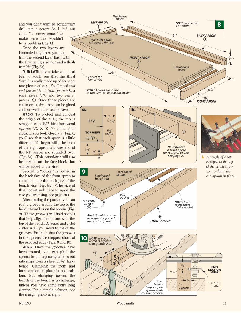
and you don’t want to accidentallydrill into a screw. So I laid outsome “no screw zones” tomake sure this wouldn’tbe a problem (Fig. 6).
Once the two layers arelaminated together, you cantrim the second layer flush withthe first using a router and a flushtrim bit (Fig. 6a).
THIRD LAYER. If you take a look atFig. 7, you’ll see that the third“layer” is really made up of six sepa-rate pieces of MDF. You’ll need twoend pieces (N), a front piece (O), aback piece (P), and two centerpieces (Q). Once these pieces arecut to exact size, they can be gluedand screwed to the second layer.
APRONS. To protect and concealthe edges of the MDF, the top iswrapped with 11/2"-thick hardwoodaprons (R, S, T, U) on all foursides. If you look closely at Fig. 8,you’ll see that each apron is a littledifferent. To begin with, the endsof the right apron and one end ofthe left apron are rounded over(Fig. 8a). (This roundover will alsobe created on the face block thatwill be added to the vise.)
Second, a “pocket” is routed inthe back face of the front apron toaccommodate the back jaw of thebench vise (Fig. 8b). (The size ofthis pocket will depend upon thevise you are using, see page 20.)
After routing the pocket, you canrout a groove around the top of thebench as well as on the aprons (Fig.9). These grooves will hold splinesthat help align the aprons with thetop of the bench. A router and a slotcutter is all you need to make thegrooves. But note that the groovesin the aprons are stopped short ofthe exposed ends (Figs. 9 and 10).
SPLINES. Once the grooves havebeen routed, you can glue theaprons to the top using splines cutinto strips from a sheet of 1/4" hard-board. Clamping the front andback aprons in place is no prob-lem. But clamping across thelength of the bench is a challenge,unless you have some extra longclamps. For a simple solution, seethe margin photo at right.
U
Scrapboards
help supportaprons while
routing grooves
#/4" %/8"
!/4"
NOTE: If end ofapron is exposed,stop groove short
10
U
T
S
R
34 "!/4
92 "!/2
35 "!/2
91"
3 "!/2
BACK APRON
FRONT APRON
LEFT APRON
RIGHT APRON
NOTE: Aprons are joinedto top with " hardboard splines!/4
Hardboardspline
Hardboardspline
Pocket forjaw of vise
Front left apronleft square for vise
NOTE: Aprons are1 " thick!/2 8
TOP VIEW1
radius!/2"
1!/2"
1!/2"
!/4"
UT
R S
a.
R
Rout pocketin front apron
for rear jaw of vise,see page 20
b.
{ A couple of cleatsclamped to the topof the bench allowyou to clamp theend aprons in place.
RRout -wide groovein edge of top and inaprons for splines
!/4"
Laminatedbench top
Hardboardspline
Visepocket
FRONT APRON
NOTE: Cutspline shortof vise pocket
SUPPORTBLOCK
M
9
!/4" slotcutter
ENDSECTION
VIEW
!/2"
%/8"
!/4"
Aprons
a.

12 Woodsmith No. 133
With the aprons attached, the 3/4"-dia.dog holes can be drilled. There’s onerow along the front edge and a dou-ble row at the end (for the vise). Tokeep the hole spacing consistent onthe long front edge (as well as to guidethe drill bit), I made the simple index-ing jig shown in Fig. 11. For the fewholes at the end of the bench, I care-fully laid out each one individually.
With the top just about complete,I added the vise. Depending on thesize of the vise you plan to install,you may need to mount a spacerblock to the underside of the benchbeforehand. Then after mountingthe vise, I added a wood face block(V) to the front jaw. You can readmore about the vise mounting pro-cedure on pages 20 and 21.
The last step to complete the topis to rout a small (1/16") chamferaround the top of the bench andaround the inside edge of the dogholes. I wanted to incorporate thevise into this chamfer detail as well,so before turning on the router, Iclosed the face block against thefront apron. Then I routed thechamfer around the top and the faceblock, as well as around the insideof each dog hole (Fig. 12).
The bearing on the chamfer bitdoesn’t allow you to rout the cham-fer all the way into the corners of theface block or the ends of the bench.So after you’re done routing, youcan clean up these inside cornerswith a chisel (Fig. 12b).
ATTACHING THE TOP. The top of thisworkbench is heavy enough that itwill stay put without being attachedto the base. But to keep the top fromshifting or sliding, I added a coupleof cleats to the underside of the top.These cleats (W) are just strips of
MDF that butt against the upperstiles, locking the top in position.But before the cleats are attached,you should make sure that the top isset squarely on the base (Figs. 13aand 13b). Then the cleats can bescrewed in place. W
NOTE: Use jig for"-dia. holes along
front edge only#/4
Drilling jig
#/4"-dia. spade bit11
With vise closed,rout " chamfer
around top of benchand dog holes
!/16
VFACEBLOCK
NOTE: Tomount vise,see page 20
12
WTOP CLEATS
NOTE: Top cleats are " MDF#/4 FIRST: Position top on base asshown in details 'a' & 'b' at right
SECOND: Attachcleats to bottomof top using glueand #8 x 1 " Fhwoodscrews
!/4
#8 x 1 " Fhwoodscrew
!/4
13
SIDE SECTION VIEW
W
NOTE: Position top toallow clearance forbench dogs
Bench dog hole
4"
TOP CLEAT
b.
FRONT SECTION VIEW
16 "!/2
Offset positionof bench top toallow for visemechanism
a.
Chamferbit
!/16"
a.
Clean up cornerswith chisel
b.
a.
CROSS SECTION
#/4"spadebit
#/4" dowel
Bench top
Drilling jig
b.
Top (continued)

14 Woodsmith No. 133
ow do you make agreat bench even
better? The answer isto add a storage unit tothe base. Actually, thedesign we came up withfeatures two storageunits — a front cabinetwith drawers and doorsand an open shelvingunit in back. And ifthat’s not enough, youcan add an optional peg-board storage panel toeach end. Build themall, and you’ll be able toput a shopful of tools atyour fingertips.
The reason for dividing the stor-age space into two separate units issimple. First, it allows you to haveaccessible storage on both sides ofthe bench. And second, it keeps thedrawers in the front cabinet at amanageable depth, so items don’tget lost at the back.
Of course, there’s no reason youhave have to build both storageunits. If you’re planning to place thebench up against a wall, you may
only want to build the cabinet infront. So let’s start with that one.
FRONT CABINETThe front cabinet is really just a ply-wood box that’s sized to fit in thespace beneath the top of the work-bench. It’s divided up into compart-ments for the drawers and cupboardstorage areas. The center section isconstructed first, and then the sidesare added later.
CENTER SECTION. The center sectionof the cabinet is plywood frameworkthat creates the openings for thedrawers. You can begin by cuttingthe top and bottom (A), two verticaldividers (B), a horizontal divider(C), and a drawer divider (D) tosize from 3/4" plywood, as shown inFig. 1 on the next page.
The front edges of all these ply-wood panels need to be coveredwith strips of 1/4"-thick hardwood
WORKBENCH STORAGE
SHOPPROJECT
Want to store a shopful of tools at your fingertips? Here’s the answer.
H
Bank of drawers. Keep your hand toolsclean and organized in these generously-sizeddrawers. Plus, they open on full-extensionslides so you can fill them from front to back.
Shelving Unit. Use every inch of the benchby adding this shallow shelving unit at theback. It’s a perfect place for jigs, hardware,and other supplies. (Plans start on page 19.)
Pegboard End Storage. In just a few minutes, you can have this optional pegboardstorage panel mounted at each end of thebench. See page 19 to find out how.

No. 133 Woodsmith 15
edging (E), as shown in Fig. 1. Ichose to do this before assemblybecause I found it a lot easier toattach and trim the edging flushwith each panel lying flat.
Once the edging is in place, youcan set up your dado blade to matchthe thickness of the plywood you’reusing (Fig. 1a). All the dadoes arethe same depth and width, so whenthe blade is set up, it’s just a matterof adjusting your rip fence to posi-tion the dadoes according to Fig. 1.
With all the dadoes cut, now is agood time to assemble the centersection. I used both glue and screwsto do this, drilling all the pilot andshank holes beforehand (Fig. 1b). Itmakes sense here to work from theinside out, starting by assemblingthe horizontal divider between thetwo vertical dividers. Then you canadd the short drawer divider andthe top and bottom panels.
SIDES. All you have to do now tocomplete the case of the cabinet isto add a couple of sides (Fig. 2).Like the other panels you cut earlier,the sides (F) are also cut from 3/4"plywood. But these panels are cut1/4" wider than the other plywoodpanels. That’s because they’ll berabbeted along the back edges laterto hold a plywood back.
After cutting the sides to size,hardwood edging is added to thefront edges. Then a rabbet is cutalong the ends of each side to holdthe top and bottom (A) of the cabi-net (Fig. 2a). Before assembling thesides to the rest of the cabinet, a 1/4"-wide rabbet is cut along the backedge of each side piece to hold a 1/4"plywood back that will be addedlater (Fig. 2b). Then the sides canbe glued and screwed in place.
SHELVES. With the case of the frontcabinet completed, the next step isto add the shelves (G). These arenothing more than a couple ofpieces of 3/4" plywood with hard-wood edging attached to the front.
The shelves are supported bybrass shelf pins. To ensure that theholes are spaced evenly and line upaccurately, I used a simple drillingtemplate that is shown in the draw-ing in the margin at right.
{ A hardboard tem-plate allows you toaccurately drill holesfor the shelf pins.
NOTE: Allparts (exceptedging) are
" plywood#/4
TOP
EDGING
BOTTOM
VERTICALDIVIDER
DRAWERDIVIDER
HORIZONTALDIVIDER
E
D
C
B
A
BA
18 "&/16
21 "!/4
1 "!/4
21 "!/4
4 "!/4
#8 x 1 "Fh wood-
screw
!/2
21 "!/4
34 "!/2
16 "&/8#/4"
4"
14 "!!/1664 "&/8
#/4"
21"
NOTE: Cut allplywood panels21" wide, thenadd "-thickedging strips
!/4
NOTE: Glueedging in placebefore cutting dadoes
B
A
!/4"
Thicknessof " plywood#/4
a.A
B
#8 x 1 "Fh wood-
screw
!/2
CROSS SECTION
NOTE: Drill"-dia.
shank holesand "-dia.pilot holesbeforeassembly
%/32
#/32
b.
SIDE
SHELF
EDGING
F
G
E
21 "!/4
19 "&/16
14 "%/16
20"
1 "!/4
NOTE: Plywood panels for sidesare cut " wider than panels
in previous drawing!/4
NOTE: Allshelf pin holesare " deep#/8
!/4" shelfpin
2
SIDE
!/4"
Thicknessof plywood
F
a.
F
Cut xrabbet inback edge ofside forback
!/4" !/4"
A
BACK VIEWb.
1
2"
2"
6 "%/8
5"
12"
SHELF PINTEMPLATE

16 Woodsmith No. 133
The center section of the cab-inet is designed to hold fivedrawers. These are graduatedin size to accommodate dif-ferent types of tools. But thenice thing is that the methodof construction is identical forall of them. So other than afew dimension changes, theprocedure is the same.
DRAWER PARTS. I started bycutting the 1/2"-thick drawerfronts and backs (H, I, J)and drawer sides (K, L) tosize (Fig. 3). The fronts andbacks are cut 1" narrowerthan the cabinet opening sothere will be clearance forthe full-extension slides.
Next the half-blind dove-tails that hold the drawertogether can be routed. Anda groove for the drawer bot-tom can be cut on theinside face of each drawerpiece. This groove is centered onthe bottom pin of the drawer sides.This way, it won’t be visible on theends of the workpieces after thedrawers are assembled.
DRAWER BOTTOMS. The drawer bot-toms (M, N) are all cut from 1/4" ply-wood. After they’re cut to size, thedrawers can be glued up.
DRAWER SLIDES. Because I wantedto be able to get to items stored at
the back of the drawers with ease,I used full-extension metal drawerslides to mount the drawers (Fig.4). One half of the slide is screwedto the side of the drawer, and theother half is screwed to the side ofthe cabinet. The important thing isthat when mounting the slide tothe cabinet, you allow 3/4" clear-ance between the slide and thefront edge of the cabinet (Fig. 4b).
This space is for the drawer falsefronts that will be added next.
FALSE FRONTS. The false fronts (O,P, Q) are cut from 3/4"-thick hard-wood (Fig. 5). They are simplyscrewed to the front of each drawerso that there is a 1/16" gap all aroundthe front of the drawer. To make iteasier to adjust the false fronts, trydrilling oversize screw holesthrough the 1/2"-thick drawer fronts
Mount drawerslides to cabinetand sides of drawers
20"drawerslide
4
9!#/16"
4!%/16"
20"full-extension
slide
FRONT VIEW
Slide sitson divider
a.
20"full-extension
slide
CROSS SECTION
#/4"
b.
N
N
M
L
L
K
K
K
J
J
I
I
H
H
SMALLDRAWER
BACK SMALLDRAWER
SIDE
MEDIUMDRAWER
SIDEMED.
DRAWERBACK
LARGEDRAWER FRONT
LARGEDRAWER
SIDE
NOTE: All drawerparts shown(except bottoms)are thick!/2"
19&/16"
19#/4"
19&/16"
19#/4"
19#/4"
4#/8"
15 /! 16"
15%/8"
3!/2"
3!/2"
32 /& 16"
33"
33"
SIDEVIEW
K
I
H
3!/2"
Small/mediumdrawer
{ How many tools can you pack into fivedrawers? Plenty. With heavy-duty, full-extension drawer slides you can make good use of every inch of each drawer.
CROSSSECTION
N
L
J
4#/8"
!/4"Plywood
Largedrawer
Drawers & Doors 3
a.
b.

No. 133 Woodsmith 17
first. Then attach the false frontsusing screws and finish washers.The oversize holes in the drawerfronts should provide enough “play”to adjust the false fronts for a perfectfit. Once the false fronts are in place,you can add the metal drawer pulls.
DOORS. To enclose the shelves oneither side of the drawers, I addedtwo doors. These are frame andpanel doors, assembled with simplestub tenon and groove joinery.
To make the doors, start by cut-ting the door rails (R) and stiles (S)to size (Fig. 6). Next, a groove is cuton the inside edge of each piece tohold a plywood frame. When thesegrooves are complete, stub tenonsare cut on the ends of the rails to fitin the grooves in the stiles.
PANELS. Each door panel is just apiece of 1/4" plywood. After cuttingthe door panels (T) to size, thedoors can be assembled.
HINGES. The cabinet doors aremounted on common butt hinges. Iwanted the hinges to match theother hardware, so I spray paintedsome ordinary steel hinges black.
After the spray paint has dried,the hinges can be attached to thecabinet. To make this as easy as pos-sible, I mortised each hinge into the
door stile, but screwed it directly tothe side of the cabinet (Fig. 6a). Andcreating the mortises in the doorstiles is easy. I simply set the dooron edge and ran it across a dadoblade on my table saw. (A tall auxil-iary miter gauge fence will help sup-port the door while you do this.)
Now that the doors are hung, apull can be added to each. Then tokeep each door closed, I installed asmall magnetic catch (Figs. 6b).These catches are mounted to theunderside of the top of the cabinet,and the strike plates are mounted tothe back of each door.
DOORPANEL
T
NOTE: Butt hingesalign with door rails
NOTE: Doorssized to have
gap on all sides.!/16"
DOORSTILE
DOORRAIL
RS
10 "%/162 "!/2
2 "!/2
17 "!#/16 13 "#/4
10 "!/4 NOTE: Doorrails and stilesare " solidwood. Doorpanels are
" plywood.
#/4
!/4
2" butthinge
Doorpull
alignswith
bottom ofdoor rail
Magneticcatch
Strikeplate
6
Thicknessofplywood!/4"
TOPSECTION
VIEW
R
2" butthinge!/2"
Through mortisecut on table saw
!/8"
S
a. CROSS SECTION
SMagnetic
catchStrikeplate
A
b.
Q
P
O
16!/2"
SMALLDRAWERFALSEFRONT
MEDIUM DRAWERFALSE FRONT
LARGEDRAWER
FALSE FRONT
NOTE: False frontsare thick#/4"
33&/8"
5
4#/4"
4#/4"
3%/8"
3%/8"
CROSS SECTION
Q
Q
P
O
NOTE:Falsefrontssized tohave
"gap onall sides.
!/16
a.
CROSSSECTION
Drawerpull
#6 x 1"Fh woodscrew
#6 finishwasher
b.
#/8"
SIDEVIEW
c.

18 Woodsmith No. 133
At this point, the front storage cabi-net is practically complete. The onlything that’s left to do is add a back. Ifyou take a look at Fig. 7, you can seethat the back is made up of three sep-arate pieces of 1/4" plywood. There aretwo back end panels (U) and a largerback center panel (V).
When measuring to determinethe sizes of these back panels, keepin mind that they fit in between therabbets cut in the sides of the cabi-net but completely cover the backedges of the cabinet top and bottom.
After the panels are cut to size,they’re simply glued and nailed tothe back of the cabinet with wirebrads (Figs. 7a and 7b).
INSTALLING THE CABINET. Installing thecabinet in the bench couldn’t bemuch simpler. It just slides into placeuntil the front edge is flush with thelower front rail of the bench.
U
U
V
NOTE: Back panels are" plywood!/4
NOTE: Cut plywood backso grain runs up and down
#16 x 1"brad
BACKCENTERPANEL
BACKEND
PANEL
34 "#/4
19 "&/1615 "%/16
7
MATERIALSFRONT STORAGE CABINET
A Top/Bottom (2) #/4 ply. - 21 x 64&/8B Vertical Dividers (2) #/4 ply. - 21 x 18&/16C Horiz. Divider (1) #/4 ply. - 21 x 34!/2D Drawer Divider (1) #/4 ply. - 21 x 4!/4E Edging (1) #/4 x !/4 - 48 lin. ft.F Sides (2) #/4 ply. - 21!/4 x 19&/16G Shelves (2) #/4 ply. - 20 x 14%/16H Sm. Drawer Fr./Bks. (4) !/2 x 3!/2 - 15%/8I Med. Drawer Fr./Bk. (2) !/2 x 3!/2 - 33J Lg. Drawer Fr./Bks. (4) !/2 x 4#/8 x 33K Sm./Med. Drawer Sides (6) !/2 x 3!/2 - 19#/4L Lg. Drawer Sides (4) !/2 x 4#/8 - 19#/4M Sm. Drawer Btms. (2) !/4 ply. - 19&/16 x 15!/16N Lg. Drawer Btms.(3) !/4 ply. - 19&/16 x 32&/16O Sm. Drawer False Fronts (2) #/4 x 3%/8 - 16!/2P Med. Drawer False Front (1) #/4 x 3%/8 - 33&/8Q Lg. Drawer False Fronts (2) #/4 x 4#/4 - 33&/8R Door Rails (4) #/4 x 2!/2 - 10%/16S Door Stiles (4) #/4 x 2!/2 - 17!#/16T Door Panels (2) !/4 ply. - 10!/4 x 13#/4U Back End Panels (2) !/4 ply. - 15%/16 x 19&/16V Back Center Panel (1) !/4 ply. - 34#/4 x 19&/16
SHELVING UNIT
W Top/Bottom (2) #/4 ply. - 7!/2 x 64&/8X Sides (2) #/4 ply. - 7#/4 x 19&/16Y Divider (1) #/4 ply. - 7!/2 x 18&/16Z Back Panels (2) !/4 ply. - 32! !/16 x 19&/16AAShelves (2) #/4 ply. - 7!/4 x 31! !/16
#16 x 1"brad
U
V
B
#/16"
TOP SECTION VIEW
a.
Plywood backsmounted flush
top and bottom
V C
ASIDESECTION
VIEW
b.
Back
#/4 !/2" x 5 " - 96" Hard Maple (3.7 Bd. Ft.)
#/4 !/4" x 9 " - 96" Hard Maple (6.2 Bd. Ft.)
R R
RR
ESSSS
Q
O O
Q
P
!/2 !/4" x 9 " - 96" Hard Maple (6.2 Sq. Ft.)
!/2 !/4" x 7 " - 96" Hard Maple (4.8 Sq. Ft.)
!/2 !/4" x 9 " - 72" Hard Maple (4.6 Sq. Ft.)
H HH H
KK K
KKK
JJ
J
J
L
L
L
L
II
ALSO NEEDED: Two sheets of " maple plywoodand two sheets of " maple plywood
#/4!/4
SUPPLIES• (48) #8 x 1!/2" Fh Woodscrews • (16) !/4" Brass Shelf Pins• (5 pr.) 20" Full-Extension Drawer Slides w/Screws• (26) #6 x 1" Fh Woodscrews• (26) #6 Finish Washers • (10) 4&/8" Door Pulls w/Screws• (2 pr.) 2" x 1!/2" Butt Hinges w/Screws• (2) Magnetic Catches w/Strikes and Screws• (76) #16 x 1" Wire Brads
CUTTING DIAGRAM

Shelving UnitThe front storage cabinet doesn’t com-pletely fill the space under the bench.So I added an open shelving unit atthe back. This unit starts off as a basicbox and features the same construc-tion as the front cabinet. But the unitisn’t as deep as the front cabinet, andthere aren’t any drawers or doors. Soit’s quite a bit easier to build.
I started building the shelvingunit by cutting the main pieces tosize. As you can see in Fig. 8, there’sa top and bottom (W), two sides(X), and a divider (Y). These panelsare all cut from 3/4" plywood andthen 1/4" hardwood edging is appliedto the front edges of each piece.
Once the edging is in place, youcan begin on the joinery. Rabbetsare cut on the ends of the sides tohold the top and bottom panels. Arabbet is also cut along the backedge of each side to hold the backpanels that will be added later.
The top and bottom panels eachreceive a dado to hold the dividerpanel (Fig. 8b). This dado is cen-tered on the length of the panels.
When you’ve finished cutting allthe rabbets and dadoes, the shelv-ing unit can be assembled. Like thecabinet, these pieces are just gluedand screwed together (Fig. 8c).
SHELF PIN HOLES. Before adding theback, some shelf pin holes need tobe drilled in the cabinet sides. AgainI used a simple template to do this.But since the spacing of these holesisn’t the same as the front cabinet,you’ll need a new template (Fig. 8a).
Once the shelf pin holes havebeen drilled, you can add a back tothe unit. This time, the back is madeup of two identically-sized panels of1/4" plywood, as shown in Fig. 9.After cutting these two back panels(Z) to final size, they can be nailedin place with brads (Fig. 9a).
SHELVES. All that’s left now is to addtwo shelves (AA). These are piecesof 3/4" plywood with a strip of hard-wood edging glued to each frontedge (Fig. 9). When the shelves arein place, you can slide the shelvingunit into the bench just like you didwith the front cabinet. W
DIVIDER
NOTE: All pieces (exceptedging) are " plywood#/4
Y
X
W
X
SIDE
7!/2"7 "#/4
7 "#/4
8"
19 "&/16
19 "&/16
64 "&/87 "#/4
18 "&/16
BOTTOM
W
TOP#8 x 1 "Fh woodscrew
!/2
#8 x 1 "Fh woodscrew
!/2
EDGINGE
No. 133 Woodsmith 19
A A
E
Z
Z
BACK PANEL( " plywood)!/4
SHELF( plywood)#/4"
7 "!/47 "!/2
31 "!!/16
Shelfpin
#16 x 1"brad
32 "!!/16
19 "&/16
9
PEGBOARD STORAGE
SHELFPIN
TEMPLATE
2"
1"2"
4%/8"
14"
a.
FRONTSECTION
VIEW
!/4"
W
Xc.
Z
W
#16 x 1"brad
SIDESECTION
VIEW
a.
CROSS SECTION
Thicknessof plywood#/4"
!/4"W
Yb.
If you’re looking for additional storage,these pegboard panels provide a con-venient place to hang a few extra tools atthe ends of the workbench. The best partis that there’s hardly anything to them.
All you need to do is nail some cleatsto the legs and upper and lower endrails of the bench. Then place a piece ofpegboard against the cleats and tack asecond set of cleats down to hold thepegboard in place. Add a few hooks,and you’re ready to hang some tools. Cleat
CleatBrad
Pegboardpanel
8

Adding a vise tothe workbench on
page 6 isn’t difficult. Infact, it’s just a three-stepprocess. First, a pocket iscut in the front apron toaccept the rear jaw of thevise. Then the vise isattached to the bench. Andfinally, a wood face block isadded to the front jaw.
But why even go to thistrouble? Why not just boltthe vise to the front apronand screw a wood pad toeach jaw? There are a cou-ple of reasons. By buryingthe rear jaw in the apron,
you have a smooth,“padded” face the lengthof the bench for clamping.The large face block hasdog holes that align withthe holes in the bench soyou can secure wide work-pieces. It also spreadsclamping pressure.
To install the vise, you’llneed to take it apart first.This isn’t as scary as itsounds. By removing acotter key, I was able toseparate the front jaw ofmy vise (along with theguide rods and threadedshaft) from the rear jaw.
Installation of the visebegins before you attachthe front apron. As youcan see in Fig. 1, a pocketis laid out and routed inthe back face of the apron.Position this pocket so thevise will be centeredbetween the dog holes inthe bench. Its size is 1/16"wider and taller than therear jaw of the vise.
Once the pocket isdone, the apron can beattached to the bench topand you can move on tothe second step — attach-ing the vise.
Start by adding a spacerblock under the benchtop. This piece fills the gapbetween the supportblock (M) and the visemounting plate (Fig. 3). Irouted a 3/8" roundover onone edge so it would fitsnugly behind the jaw.After the spacer is cut tosize, it’s glued in place.
Next, a series of holesneeds to be drilled. If youlook at Fig. 2, you’ll seetwo counterbored holes inthe top of the bench.These accept hex-headbolts that pass through
20 Woodsmith No. 133
CROSSSECTION
#14 x 2" Fhwoodscrew
Spacer block
Accesshole
b.
3 "!/16
Width ofvise plus "!/16
Front apron9"
1
3 "!/16(/16"
CROSS SECTION
SUPPORTBLOCK
Front apron
Visepocket
Bench top
M
a.
9" Lay outvise mounting
holes fromcenterline
2
M
1"
3 "!/2
1 "#/4
CROSS SECTION
!/2"
Spacer block
a.
SHOP NOTES
TIPS FROMOUR SHOP
Mounting a Vise
NOTE: Remove frontjaw (with rods) beforeattaching rear jawto bench
SUPPORT BLOCK
Spacer block(1 " thick)!/4
M
Vise
NOTE: Vise iscentered betweendog holes in bench
FIRST: Gluerails to bench top
Cotterpin
SECOND: Addspacer block
THIRD: Lay outmounting holes in benchtop and front apron
6"
15"
Hex-headbolt
3M
#/8"round-over
%/16 !/2" x 4 "hex-head bolt
Lock nutand washer
CROSSSECTION
ViseSpacer block
a.

Auxiliary fence
Clamp hold-downto auxiliary fence to
prevent rail from tipping
Outriggersupport
Sawhorse
NOTE: Position topedge of outrigger supportlevel with table saw wing
Rail
1
the vise. And two holesthrough the front apronallow access to screwsthat attach the rear jaw tothe bench (Fig. 3b).
To lay out the holes inthe bench top, you want towork out from the center-line of the pocket in theapron and the centerlineof the mounting plate.
The next thing to do isto drill the access holesthrough the front apron(Fig. 2). These holes needto be big enough to allowthe screws to passthrough. Here again, layout the holes by workingfrom the centerlines of therear jaw and the pocket.
The third step is mak-ing and mounting thewood face block (V). Thisconsists of two slabs of11/2"-thick maple gluedtogether (Fig. 4). Beforedoing that, a radius needsto be cut on each end ofone block as you can seein Fig. 4a. I did this on theband saw, then sanded thecurves smooth.
After gluing the piecestogether, lay out and drill acouple of dog holes in thejaw so that they align withthe holes in the bench.Then to mount the faceblock, just use the vise toclamp the block againstthe apron with the topedges and ends flush(Figs. 4a and 4b). Twoscrews secure it to the jaw.
When you close the
jaws of the vise, you’llnotice a small gapbetween the apron andthe bottom of the faceblock, like you see in thephoto at right. Don’tworry. The vise jaws cant(tilt) in slightly at the top.The reason is that as youclamp a workpiece, itforces the top of the viseapart. This tilt keeps thejaws parallel. W
No. 133 Woodsmith 21
Auxiliary fence
Hold-down
ENDVIEW
Outriggersupport
Sawhorse
Table saw
a.
When it was time to cut thetenons on the rails for theworkbench on page 6, Ineeded a way to handle thelong pieces safely.
Fig. 1 shows the “outrig-ger” system I came upwith to support the endsthat extend past the wingof the table saw. Justclamp a board to a sawhorse so that it matchesthe height of the wing.
An auxiliary fenceattached to the mitergauge helps support thepiece. And a hold-downclamped to the fencekeeps the rail pressedfirmly to the table. Thislets you use both hands topush the workpiecethrough the cut. W
Cutting Tenons on Long Rails
1 "!/2
4 "!/2
17!/2"
FACE BLOCKV
Use vise to clamp face blockto apron, then drill pilot holes
for #14 x 2" Fh woodscrews
18"
41 "!/2
3 "!/2
1 "!/2
!/4"
TOP VIEW
Doghole
FACEBLOCK
Frontapron
a.
#14 x 2"Fh screw
FACE BLOCK
CROSS SECTION
1"
b.
{ The top edges of the jaws tilt in slightlyto counteract the forces of clampingthat tend to drive the top edges apart.

No. 133 Woodsmith 13No. 133 Woodsmith 13
TOOLS OFTHE TRADE
Even the sturdiest bench is nothingmore than a fancy table if you can’thold your work to it securely. That’swhere all the holes drilled throughthe top of the workbench come in.These holes accept accessories thatkeep your work where you want it.
BENCH DOG. The simplest of theseitems is a type of bench dog, shownin the left photo below. It’s just acylinder with a flat face at one endand a spring in the side. A singledog can be used as a stop whenplaning or scraping a board. Andsince the dog is brass, it’s less likelyto damage a cutting edge if your
plane or chisel slips. (Rubber facepads are also available, see thephoto above.) By using dogs in theface block of the vise and a couplemore dogs in the bench, you canclamp wide panels easily.
WONDER PUP. Bench dogs alonewon’t handle every clamping situa-tion. What if you want to hold a longpiece from each end? Or need aboard clamped along the front edgeof the bench? That’s where aWonder Pup comes in handy (mid-dle photo). The name might soundlike a kid’s toy or a super hero’s pet,but it’s actually a small vise that fits
in any 3/4" dog hole. Use it with abench dog (or another WonderPup) to secure a workpiece. Andtwo holes in the head of the Pup letyou screw a shop-made block to it.
HOLD-DOWN. Sometimes you justneed to hold a workpiece flat to thebench top. In these cases, you needa hold-down (photo below). Thelong shaft allows you to clamp itemsup to 8" thick. Turning a threadedknob gradually adjusts the pressurethe arm places on the workpiece.
Note: These accessories are man-ufactured by Veritas. See page 35for mail-order sources. W
VISE MOUNTING PLATE
14!/2" 8 "!/2
#/8"-dia.hole
#/4"-dia. dowel,1" long2 "!/4
PLATE( MDF)#/4"
Place vise on base tolay out mounting holes
When you need to cut metal pieces,it’s best to use a machinist’s vise tohold them. The wood faces of theworkbench and vise can be scarredif you nick them with a hack saw ortry to clamp down on a threaded rod.But since I don’t use my machinist’svise very often, this plate lets memount it to the bench temporarily, asshown in the photo.
In the bottom of the plate are two3/4"-dia. dowel pins, spaced to fit apair of dog holes. A bolt and wingnut secure the assembly to thebench top through a third dog hole.
Round bench dogs. Put dogs in thebench top and vise, and you can clampworkpieces in a variety of ways.
Wonder Pup. With its threadedshaft, the Pup serves as an end visethat can be placed in any dog hole.
Veritas hold-down. To keep yourwork clamped firmly to the bench,just tighten the knob on the top.
!/2"
1#/4"
#/8 !/2" x 3 "hexhead
bolt
Washer
Wingnut#/8" T-nutCounterbore so T-nut
sits below surface
Vise mounting bolts must notextend past bottom of base
5 "!/2
WORKBENCHACCESSORIES
{ When you need an extra pair ofhands, these benchaccessories helpyou get a grip onyour projects.


