IJR International Journal of Railway
Vol. 8, No. 1 / March 2015, pp. 5-9
Vol. 8, No. 1 / March 2015 − 5 −
The Korean Society for Railway
Sensitivity Analysis by Parametric Study of Load Factor for a
Concrete Box Girder Railway Bridge Using Limit State Design
Inho Yeo†, Hyung-Bo Sim*, Daehwan Kim** and Yonghan Kim**
Abstract
Reliability based limit state design method is replacing traditional deterministic designs such as allowable stress design
and/or ultimate strength design methods in world trends. European design code(Eurocode) has adopted limit state design,
and Korea road bridge design standard has also recently been transferred to limit state design method. In this trend,
Korea railroad design standard is also preparing for adopting the same design concept. While safety factors are deter-
mined empirically in traditional design, load combinations as well as load factors are determined by solving limit state
equations. General partial safety factors are evaluated by using AFORM(Advanced First Order Reliability Method) in
the reliability based limit state design method. In this study sensitivity analysis is carried out for a dead load factor and a
live load factor. Relative precisions of the dead load and the live load factors are discussed prior to the AFORM analy-
sis. Furthermore the sectional forces of design and the material quantities required by two different design methods are
compared for a PSC box girder railway bridge.
Keywords: Railway bridge, Reliability based design, Limit State Design, Sensitivity analysis, Load factor,
1. Introduction
1.1 Design methods
Allowable stress design(ASD) and ultimate strength
design(USD) methods have been widely used for struc-
tural design as a deterministic design concept. The ASD is
based on the elastic analysis in which a structural member
shows elastic behavior under service loads. Because the
elastic behavior is assumed in the ASD method, the princi-
ple of proposition is valid. Member stresses are evaluated
for each predicted load. The most unfavorable combina-
tion stress should be below the allowable stress. The ASD
method is usually used for steel structures that show elas-
tic behavior. The stress-strain curve is assumed to be lin-
ear and the tensile bending stress of concrete is ignored for
the reinforced concrete structure.
In the USD method, load factors as well as strength
reduction factors are used to determine a proper section of
a structure. The load and the strength reduction factors
represent the statistical uncertainty of the action and the
resistance in some degree. The design strength, that is the
multiplied value of the nominal strength and the strength
reduction factor, should be larger than the required
strength which is the multiplication of the load factor and
the service load. The strength reduction factor and the load
factor reflect an uncertainty of the material property and
the overload, respectively. The USD is usually used for
concrete structures.
The ASD concept is simple but it may not be inade-
quate to account for the variability. Different load factors
can be used in the USD depending on uncertainty the load,
but it is more complicated than the ASD. For concrete rail-
way bridges the USD is generally applied while the design
is checked by the ASD afterwards.
Since 1980’s there has been a great deal of research
effort for developing the limit state design(LSD) method.
The LSD adopts a reliability based design concept that
explicitly accounts for the uncertainties safer and more
economical designs compared with the traditional deter-
†
*
**
Corresponding author: Korea Railroad Research Institute, Korea
E-mail : [email protected]
Korea Railroad Research Institute, Korea
IDM, Korea
ⓒThe Korean Society for Railway 2015
http://dx.doi.org/10.7782/IJR.2015.8.1.005

− 6 −
Inho Yeo, Hyung-Bo Sim, Daehwan Kim and Yonghan Kim / IJR, 8(1), 5-9, 2015
ministic designs. The LSD has been recently adopted in
Europe as a typical design concept replacing with the tra-
ditional ASD and USD. The reliability based design
method such as LSD or LRFD(Load and Resistance Fac-
tor Design) has also been recently applied for design of
road bridges as well as concrete and steel structure in
Korea.
1.2 Limit state deign method
Traditional deterministic design uses safety factors to
assess the safety. Because the structural resistance and the
load are evaluated by the deterministic method, the safety
factors in the traditional design method are determined
empirically. In most cases, deterministic design can lead to
not only an uneconomical design but also occasionally
unsafe designs. The reliability based design method is
Load and Resistance Factor Design(LRFD) developed in
North America, and the LSD in Europe.
Load and resistance factors in the reliability based
design method are developed from current statistical infor-
mation or data on loads and structural performance and
calibrated through the theory of reliability. A limit state in
the design method is a specified structural condition,
beyond which a structure or a component of a structure
ceases to satisfy its intended design function. There are
four limit sates in the AASHOTO LRFD, each with a cor-
responding set of load combinations.
- Service limit state that provides restrictions on stress,
deformation and crack width
- Fatigue and fracture limit state that controls crack
growth under repetitive load
- Strength limit state that provides strength and stability,
locally and globally
- Extreme event limit state that ensures structure sur-
vival from an earthquake or other rare-occurrence
events
For each load case in the four limit states, the following
equation must be satisfied;
(1)
Where,
: nominal resistance
: resistance factor
: nominal load effect
: load factor
: load modifier
Limits states are classified into ultimate limit states and
serviceability limit states in the Eurocode. The ultimate
limit states concern the safety of people and the structure.
The limit states that concern the functioning of the struc-
ture or structural members under normal use, the comfort
of people, and the appearance of the construction works,
shall be classified as serviceability limit states Design for
limit states shall be based on the use of structural and load
models for relevant limit states.
1.3 Reliability based design method
Both the LSD and LRFD use structural reliability based
design concept. Structural reliability is the application of
probabilistic principles to an evaluation of acceptable and
unacceptable structural performance. Safety can be mea-
sured in terms of the probability of uninterrupted opera-
tion under a given set of conditions. In Korea, reliability
based design method has been recently introduced in
world trends. The deterministic steel and concrete struc-
ture design standards were replaced by reliability based
design. The reliability based limit state design method
was released as a Korea road bridge design criteria in
2012, and it is supposed to be used as an obligatory regu-
lation for road bridge design from 2015. Especially the
Eurocode adopts the reliability based limit state design for
railway bridges as well as road bridges. The Eurocode
consolidates the two design standards of road and rail-
way into one. EN 1991(Eurocode 1) only defines actions
on structures according to transportation system. Such
unified criteria may be reasonable because both bridge
types have similar shapes, forms, functions, and materials
except for live load. Therefore, if the statistical parame-
ters of railway live load are evaluated, the reliability
based limit state design method for railway bridges can be
established.
While the safety factor in the ASD determined empiri-
cally, the reliability based design method, the safety factor
based on the probability of failure. It is defined using of
the probability of failure(or the reliability index). It is pos-
sible that the reliability based design secures an uniform
safety for structures and their components. Uncertainties
of various design parameters are considered by their statis-
tical data. Because individual partial safety factors can be
determined according to characteristics of each design
variables, it is essential to provide the statistical data. In
this view, the statistical data of train live loads are required
to establish the reliability based limit state design standard
for railway bridges.
1.4 Evaluation procedure of reliability based
load-resistance factors
Defining limit states is the first step in the establishment
of reliability based design. Limit states can be classified
into ultimate limit states and serviceability limit states as
previously mentioned. A target reliability index is then
ηiγiQ
niφR
n≤∑
Rn
φ
Qni
γi
ηi
Sensitivity Analysis by Parametric Study of Load Factor for a Concrete Box Girder Railway Bridge Using Limit State Design
− 7 −
determined for the limit states. Load and resistance factors
shall finally be determined statistically such that the reli-
ability of each case complies with the target reliability.
The target reliability index is determined in the range of
3.5~3.8 as a level of ultimate limit state(or strength limit
state) in the Eurocode and the AASHTO LRFD, respec-
tively. The reliability index is evaluated by Level II in
which the statistical distribution of variables is assumed as
independent normal distribution, and the index is esti-
mated by the mean and the variation. In case that the sta-
tistical variables do not have normal distribution,
Rackwiz-Fiezzler transform can be applied to transform
the non-normal variable to the normal variable. In gen-
eral, reliability index of 3.72 means failure probability of
1/10,000. The partial safety factors(resistant and load fac-
tors) can then be evaluated by AFORM(Advanced First
Order Reliability Method) to assure the target reliability
index. With the bias factor of individual design variable
determined, the individual partial safety factor can be cal-
culated, the bias factor means the ratio of mean value to
nominal value.
1.5 Objective of the Paper
The reliability based limit state design method has recently
been adopted as structural design standards in Korea. The
design standard for road bridges has been changed to the
limit state design standard. In light of this trend in design cri-
teria, the reliability based design method is expected to be
introduced for rational and economic railway bridge design.
Some specific steps are required to develop the reliability
based design method for railway bridges.
- Generate load combination according to limit states
- Develop reliability based load and resistance factors
- Investigate the need for a new live load model
- Develop separate factors for load rating or modify the
developed design factors
- Calibrate against existing simulated railway bridge
designs
Load factors should be determined based on the statisti-
cal properties of loads in Korea. Prior to the preparation of
full-fledged limit state design method for railway bridges,
sensitivity of load factor is investigated to each load com-
bination of the limit states in this paper. The results can be
used to determine load factors adequate for domestic cir-
cumstances in Korea.
A high-speed railway bridge, which was designed in the
past according to the Korean Railway Bridge Design
Code(KRBDC), has been redesigned by using the limit
state design method of the Eurocode in this paper. The total
weight decrement of rebar in the redesign is evaluated, and
the sensitivity of each load factor is then analyzed
2. Comparison of Design Sections by Two Design Methods
2.1 Bridge for analysis
The object of the high speed railway bridge in this study
is a representative PSC-box girder-bridge on the Ho-nam
high speed railway line. Its span length, width, and height
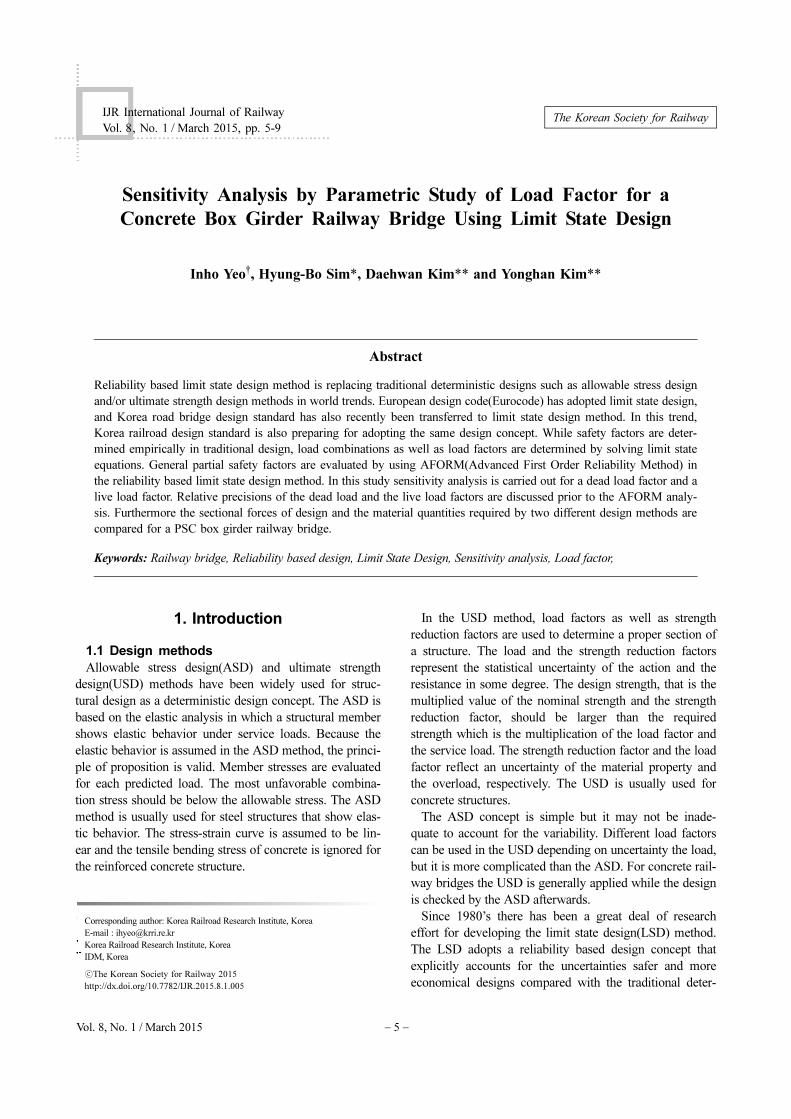
are 35 m, 12.6 m, and 3.5 m, respectively. Fig. 1 shows the
cross sections of a simply supported girder bridge
designed according to KRBDC.
The design compressive strength of concrete, design
yield strength of rebar, and the design yield strength of ten-
don are 40 MPa, 400 MPa, and 1,880 MPa, respectively.
Table 1 and 2 show prescribed load cases in the KRBDC
and the Eurocode, respectively. Because main sectional
force is induced vertically and the girder is single span,
Fig. 1 Girder sections by the current design specification
Table 1 Load factors in the KRBDC
Load case D PS L W T
LC 1 1.4 1.0 1.4
LC 2 1.45 1.0 1.45
LC 3 1.8 1.0 1.80
LC 4 1.4 1.0 2.33 1.4
LC 5 1.4 1.0 1.4 1.4 1.4
Table 2 Load factors in the Eurocode
Load case D PS L W T
ULS1 1.35 1.0 1.45
ULS 2 1.35 1.0 1.45 0.9
ULS 3 1.35 1.0 1.5
ULS 4 1.35 1.0 1.45 1.5 0.9
ULS 5 1.35 1.0 1.45 1.4 0.9
− 8 −
Inho Yeo, Hyung-Bo Sim, Daehwan Kim and Yonghan Kim / IJR, 8(1), 5-9, 2015
thermal load(T) and wind load(W) do not affect the girder
behavior. Midas Civil, a structural analysis software was
used for structural design. Applied loads(live load, self-
weight, secondary dead load, wind load, thermal load) are
identical as those used in the design for Honam high speed
railway line.
Five dominant load cases are considered for strength
design criteria of PSC box girder in the KRBDC. In the
Eurocode, combination factors are considered for ultimate
limit states of permanent action, leading variable action,
accompanying variable action. Load factors are shown in
Table 1 and 2 for the KRBDC and the Eurocode, respec-
tively. The limit sectional moment and shear force are
evaluated for normal design state load factors.
2.2 Material quantity comparisons by two
design methods
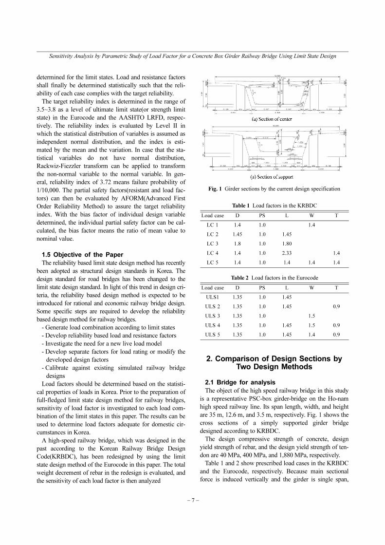
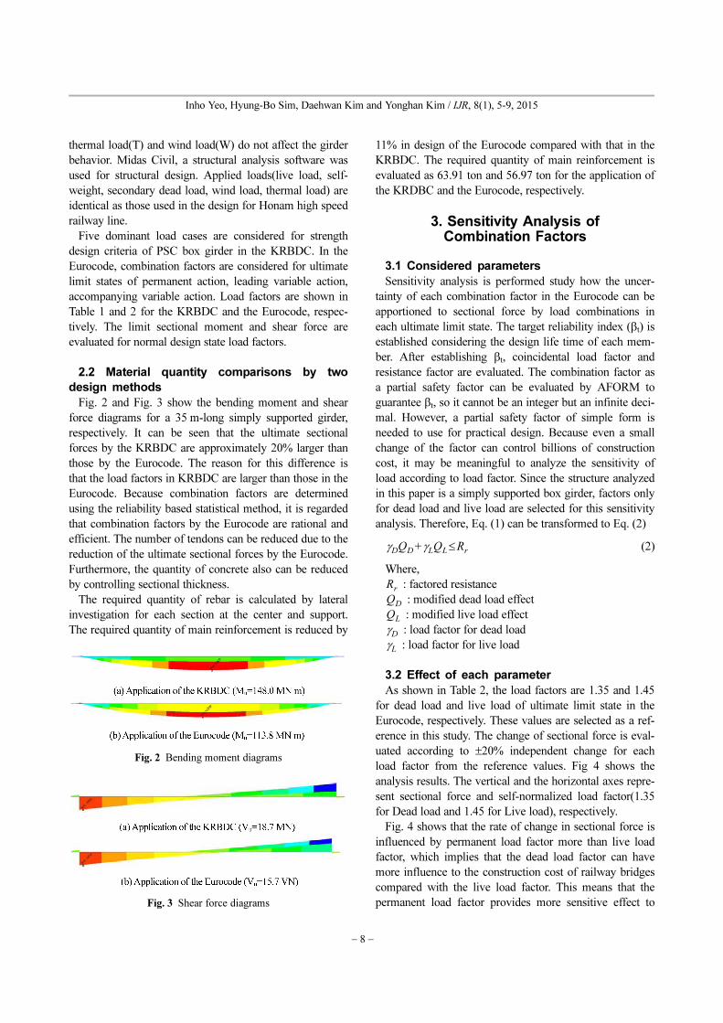
Fig. 2 and Fig. 3 show the bending moment and shear
force diagrams for a 35 m-long simply supported girder,
respectively. It can be seen that the ultimate sectional
forces by the KRBDC are approximately 20% larger than
those by the Eurocode. The reason for this difference is
that the load factors in KRBDC are larger than those in the
Eurocode. Because combination factors are determined
using the reliability based statistical method, it is regarded
that combination factors by the Eurocode are rational and
efficient. The number of tendons can be reduced due to the
reduction of the ultimate sectional forces by the Eurocode.
Furthermore, the quantity of concrete also can be reduced
by controlling sectional thickness.
The required quantity of rebar is calculated by lateral
investigation for each section at the center and support.
The required quantity of main reinforcement is reduced by
11% in design of the Eurocode compared with that in the
KRBDC. The required quantity of main reinforcement is
evaluated as 63.91 ton and 56.97 ton for the application of
the KRDBC and the Eurocode, respectively.
3. Sensitivity Analysis ofCombination Factors
3.1 Considered parameters
Sensitivity analysis is performed study how the uncer-
tainty of each combination factor in the Eurocode can be
apportioned to sectional force by load combinations in
each ultimate limit state. The target reliability index (βt) is
established considering the design life time of each mem-
ber. After establishing βt, coincidental load factor and
resistance factor are evaluated. The combination factor as
a partial safety factor can be evaluated by AFORM to
guarantee βt, so it cannot be an integer but an infinite deci-
mal. However, a partial safety factor of simple form is
needed to use for practical design. Because even a small
change of the factor can control billions of construction
cost, it may be meaningful to analyze the sensitivity of
load according to load factor. Since the structure analyzed
in this paper is a simply supported box girder, factors only
for dead load and live load are selected for this sensitivity
analysis. Therefore, Eq. (1) can be transformed to Eq. (2)
(2)
Where,
: factored resistance
: modified dead load effect
: modified live load effect
: load factor for dead load
: load factor for live load
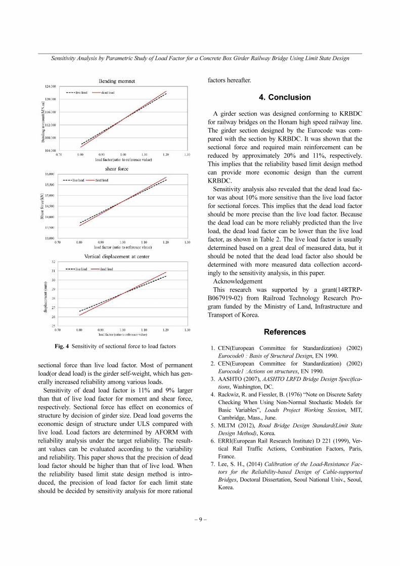
3.2 Effect of each parameter
As shown in Table 2, the load factors are 1.35 and 1.45
for dead load and live load of ultimate limit state in the
Eurocode, respectively. These values are selected as a ref-
erence in this study. The change of sectional force is eval-
uated according to ±20% independent change for each
load factor from the reference values. Fig 4 shows the
analysis results. The vertical and the horizontal axes repre-
sent sectional force and self-normalized load factor(1.35
for Dead load and 1.45 for Live load), respectively.
Fig. 4 shows that the rate of change in sectional force is
influenced by permanent load factor more than live load
factor, which implies that the dead load factor can have
more influence to the construction cost of railway bridges
compared with the live load factor. This means that the
permanent load factor provides more sensitive effect to
γDQ
DγLQ
LRr
≤+
Rr
QD
QL
γD
γL
Fig. 2 Bending moment diagrams
Fig. 3 Shear force diagrams
Sensitivity Analysis by Parametric Study of Load Factor for a Concrete Box Girder Railway Bridge Using Limit State Design
− 9 −
sectional force than live load factor. Most of permanent
load(or dead load) is the girder self-weight, which has gen-
erally increased reliability among various loads.
Sensitivity of dead load factor is 11% and 9% larger
than that of live load factor for moment and shear force,
respectively. Sectional force has effect on economics of
structure by decision of girder size. Dead load governs the
economic design of structure under ULS compared with
live load. Load factors are determined by AFORM with
reliability analysis under the target reliability. The result-
ant values can be evaluated according to the variability
and reliability. This paper shows that the precision of dead
load factor should be higher than that of live load. When
the reliability based limit state design method is intro-
duced, the precision of load factor for each limit state
should be decided by sensitivity analysis for more rational
factors hereafter.
4. Conclusion
A girder section was designed conforming to KRBDC
for railway bridges on the Honam high speed railway line.
The girder section designed by the Eurocode was com-
pared with the section by KRBDC. It was shown that the
sectional force and required main reinforcement can be
reduced by approximately 20% and 11%, respectively.
This implies that the reliability based limit design method
can provide more economic design than the current
KRBDC.
Sensitivity analysis also revealed that the dead load fac-
tor was about 10% more sensitive than the live load factor
for sectional forces. This implies that the dead load factor
should be more precise than the live load factor. Because
the dead load can be more reliably predicted than the live
load, the dead load factor can be lower than the live load
factor, as shown in Table 2. The live load factor is usually
determined based on a great deal of measured data, but it
should be noted that the dead load factor also should be
determined with more measured data collection accord-
ingly to the sensitivity analysis, in this paper.
Acknowledgement
This research was supported by a grant(14RTRP-
B067919-02) from Railroad Technology Research Pro-
gram funded by the Ministry of Land, Infrastructure and
Transport of Korea.
References
1. CEN(European Committee for Standardization) (2002)
Eurocode0 : Basis of Structural Design, EN 1990.
2. CEN(European Committee for Standardization) (2002)
Eurocode1 :Actions on structures, EN 1990.
3. AASHTO (2007), AASHTO LRFD Bridge Design Specifica-
tions, Washington, DC.
4. Rackwiz, R. and Fiessler, B. (1976) “Note on Discrete Safety
Checking When Using Non-Normal Stochastic Models for
Basic Variables”, Loads Project Working Session, MIT,
Cambridge, Mass., June.
5. MLTM (2012), Road Bridge Design Standard(Limit State
Design Method), Korea.
6. ERRI(European Rail Research Institute) D 221 (1999), Ver-
tical Rail Traffic Actions, Combination Factors, Paris,
France.
7. Lee, S. H., (2014) Calibration of the Load-Resistance Fac-
tors for the Reliability-based Design of Cable-supported
Bridges, Doctoral Dissertation, Seoul National Univ., Seoul,
Korea.
Fig. 4 Sensitivity of sectional force to load factors


