Download - senior year portfolio small
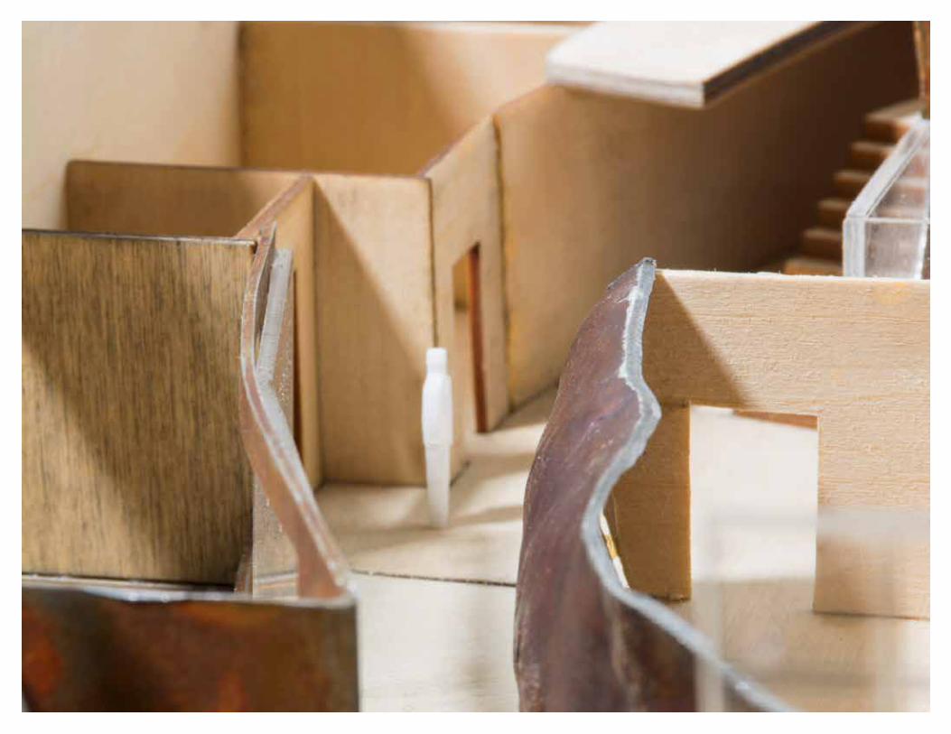

Table of Contents
Pearl Street Office Space
Revit Cabin
Experiential Bridge
Roman Brewery
Modular Chair
Heuristic Sculpture
Freedom of Speech Pavilion
p. 4
p. 11
p. 18
p. 26
p. 32
p. 36
p. 38
Pearl Street Office Space
Warren MillerEntertainment
This new Warren Miller office would be the new headquarters located in Boulder, Colorado on Pearl Street and 9th. This two story complex has around 25 office desks. There is a sound room, video editing space, road crew space, two conference rooms, HR office, a social outdoor space, and it is wheel chair accessible.
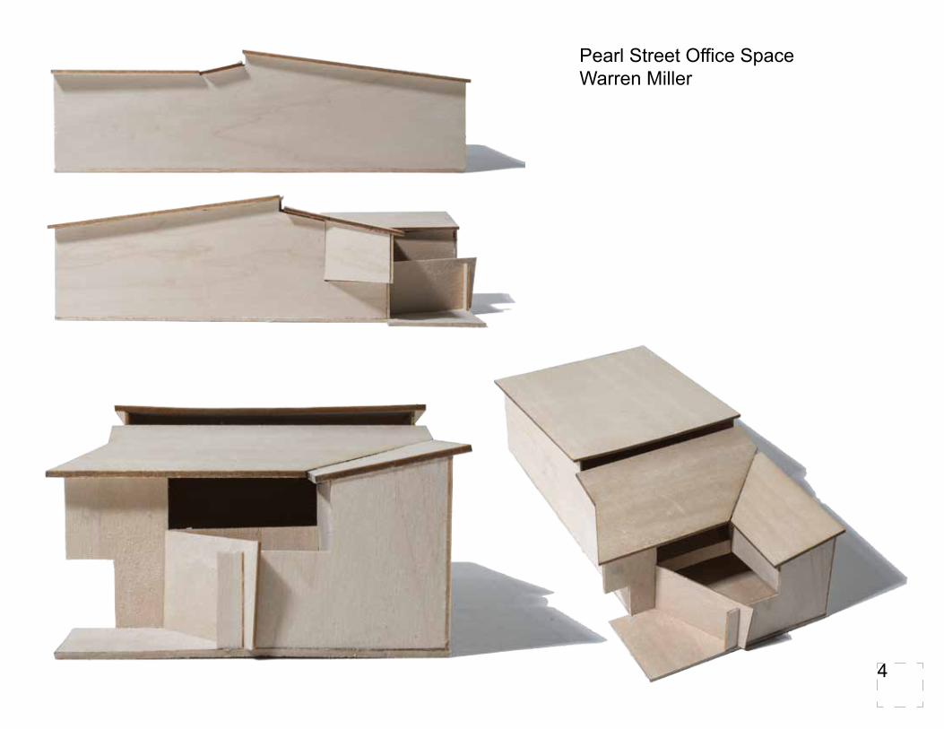
Pearl Street Office SpaceWarren Miller
4
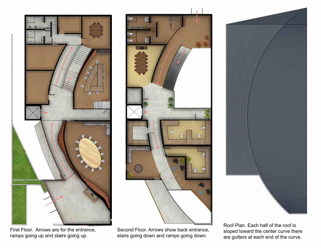
First Floor. Arrows are for the entrance, ramps going up and stairs going up.
Second Floor. Arrows show back entrance, stairs going down and ramps going down.
Roof Plan. Each half of the roof is sloped toward the center curve there are gutters at each end of the curve.
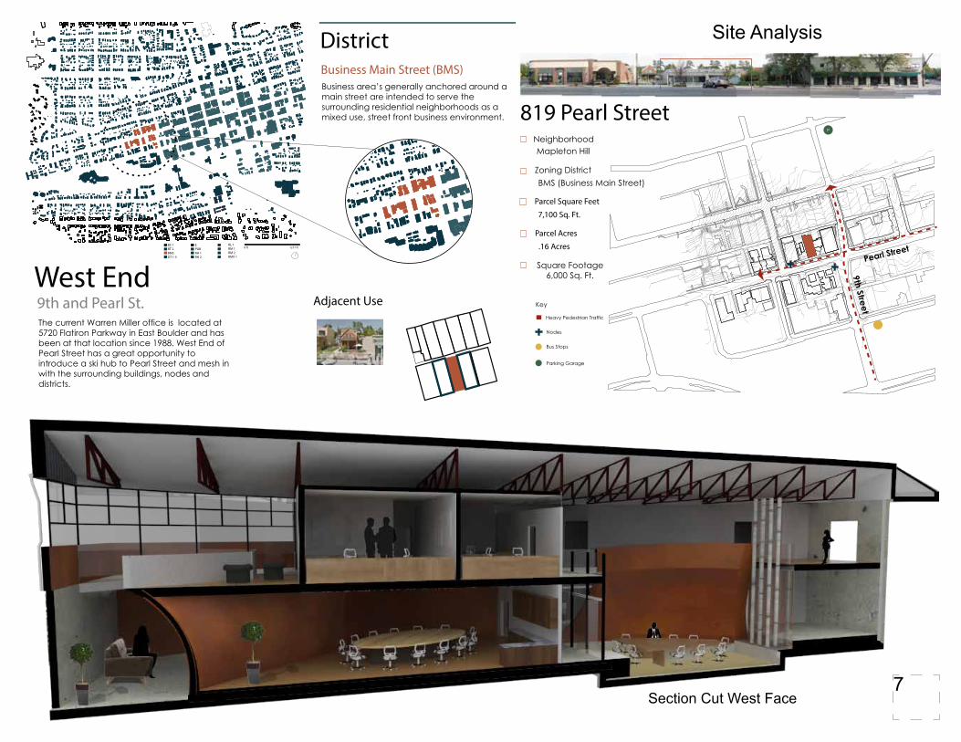
Section Cut West Face
9th and Pearl St.
0 ft 1217 ft
Business Main Street (BMS)
Adjacent Use
District
819 Pearl Street
BC 1BT 2BMSDT 1-5
EPUBRH 1RH 2
RL 1RM 1RM 2RMX 1
The current Warren Miller office is located at 5720 Flatiron Parkway in East Boulder and has been at that location since 1988. West End of Pearl Street has a great opportunity to introduce a ski hub to Pearl Street and mesh in with the surrounding buildings, nodes and districts.
West End
Business area’s generally anchored around a main street are intended to serve the surrounding residential neighborhoods as a mixed use, street front business environment.
Neighborhood Mapleton Hill
Zoning DistrictBMS (Business Main Street)
Parcel Square Feet
7,100 Sq. Ft.
Square Footage 6,000 Sq. Ft.
Parcel Acres
.16 Acres
Heavy Pedestrian Traffic
Key
Nodes
Bus Stops
Parking Garage
Pearl Street
9th Street
P
Site Analysis
7
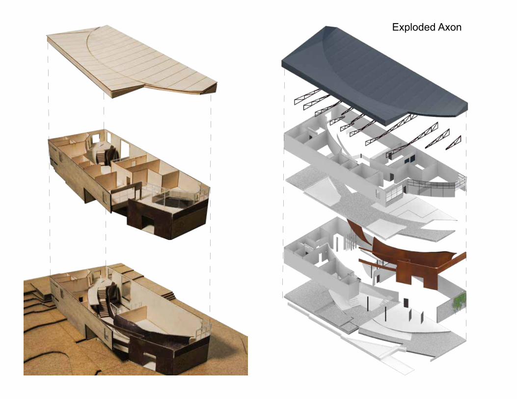
Exploded Axon
Exploded Axon
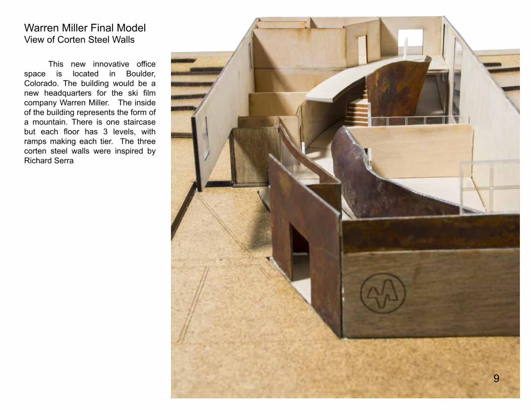
This new innovative office space is located in Boulder, Colorado. The building would be a new headquarters for the ski film company Warren Miller. The inside of the building represents the form of a mountain. There is one staircase but each floor has 3 levels, with ramps making each tier. The three corten steel walls were inspired by Richard Serra
Warren Miller Final ModelView of Corten Steel Walls
9


Revit Class:
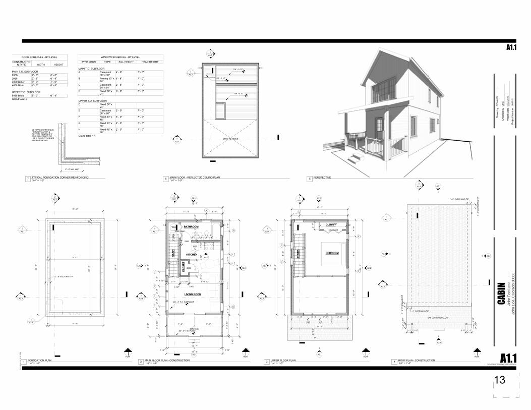
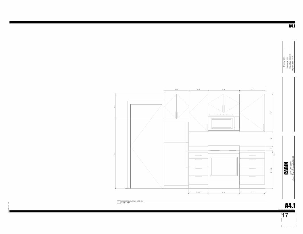
Cabin CD Drawing
10

UP
UP
6093' - 0"
609
3' -
0"
6094' - 0"
609
4' -
0"
6095' - 0"
6095
' -0"
6096' - 0"
6096
' -0"
6097' - 0"
6097
' -0"
6098' - 0"
6098
' -0"
WH
FUR
N
90° 00' 00"100.00'
N W
0° 0
0' 0
0"10
0.00
'S
W
90° 00' 00"100.00'
N W
0° 0
0' 0
0"10
0.00
'N
E
ADJACENT LOT
ADJA
CEN
T LO
T
ADJA
CEN
T LO
T
ADJACENT LOT
1A101
SIM
1A101
1A101
1A101
A1011 SIM
A1011 SIM
A1011 SIM
A1011
BUILDING SECTION(PLAN)
BUILDING SECTION NUMBER
SHEET NUMBER
BUILDING SECTION(ELEVATION)
ELEVATIONS
WALL SECTION
DETAIL CALLOUTDETAIL NUMBER
SHEET NUMBER
DETAIL CUT(PLAN/SECTION)
RELATED DETAILCUT BELOW ORABOVE
ROOM NAMEFLOOR FINISH
101
NAMEELEVATION
NAMEELEVATION
DRAWING NAMESCALE1
ACTUAL NORTH
ROOM NAME WITHFLOOR FINISH
ROOM NAME
FLOOR FINISH
DOOR TAG
WINDOW TAG
REVISION TAG
LEVEL TAGS
LEVEL NAME
LEVEL ELEVATION
DRAWING TITLE
NORTH ARROWS WORKING NORTH
403 SFUPPER FLOOR AREA
403 SFMAIN FLOOR AREA
Pro
ject
Dat
e
Che
cked
by
Dra
wn
by
Pro
ject
Num
ber
John
Doe
Lan
eJo
hn D
oe, C
olor
ado
8000
0
2/23
/201
6 10
:31:
55 P
M
CABI
N
A0CONSTRUCTION DOCUMENTATION
1602
15
ED
WA
RD
LMC
2/22
/201
6
A0
pfecontact
OwnerPamela Anderson342 Wallibie DriveSomewhere, CO 80XXX
303.000.0000
JohnDoe@John Doe
pfecontact
DesignerEDWAD SWEENEY123 LOLLILORD LANEBoulder CO, 80303
[email protected] Sweeney
1" = 10'-0"1 SITE PLAN North2 AXONOMETRIC SOUTHEAST
DRAWING LIST
NO NAME
A0 COVERA1.1 PLANSA2.1 NORTH AND SOUTH
ELEVATIONSA2.2 EAST AND WEST
ELEVATIONSA3.1 BUILDING SECTIONSA4.1 INTERIOR ELEVATIONS
1/2" = 1'-0"DRAWING SYMBOL LEGEND
1/8" = 1'-0"4 UPPER FLOOR PLAN - AREA PLAN 1/8" = 1'-0"3 MAIN FLOOR PLAN - AREA PLAN
AREA SCHEDULE (Rentable)
aerAemaN
MAIN FLOOR AREA 403 SFUPPER FLOOR AREA 403 SFGrand total: 2
WINDOW SCHEDULE
Type Mark Type Count Sill Height Head Height
A Casement30" x 30"
1 4' - 6" 7' - 0"
B Awning 30" x18"
1 5' - 6" 7' - 0"
C Casement30" x 54"
6 2' - 6" 7' - 0"
D Fixed 24" x24"
3
E Casement30" x 60"
1 2' - 0" 7' - 0"
F Fixed 20" x48"
2 3' - 0" 7' - 0"
G Fixed 30" x60"
2 2' - 0" 7' - 0"
H Fixed 48" x60"
1 2' - 0" 7' - 0"
Grand total: 17
DOOR SCHEDULE
ConstructionType Width Height Comments Count
1"8 - '6"0 - '4dlofiB 86041"8 - '6"6 - '286621"8 - '6"6 - '286621"0 - '7"0 - '6redilS 07031"8 - '6"0 - '5dlofiB 8605
Grand total: 5
UP
WH
FUR
N
REF.
UP
UP
1A3.1
2A3.1
15' - 6"
26' -
0"
26' -
0"
15' - 6"8"
8"25
' - 4
"
8" 14' - 2" 8"
1' - 6" FOOTING TYP.
3A3.1
A1.17
A2.21
A2.1
A2.2
A2.1
1
2
2
1A3.1
2A3.1
15' - 6"
26' -
0"
6' -
0"
26' -
0"
6' -
0"
15' - 6"
5 1/
2"
5' -
6 1/
2"
5 1/
2"5'
- 6
1/2"
2' -
4"2'
- 9"
2' -
9"4'
- 0"
5 1/2"
14' - 7"
5 1/2"
5 1/
2"5'
- 1"
5 1/
2"
4' -
10"
3 1/
2"
4' -
1"
3 1/
2"
5 1/2" 3' - 1"
3 1/2"
2' - 2 1/2"
3 1/2"
8' - 8 1/2" 5 1/2"
7' - 9" 7' - 9"
3070 Slider
2668
2668
4068 Bifold
6"
11' - 0" 4' - 6"
3' -
0"6'
- 5"
2' -
6"11
' - 1
1"2'
- 2"
C
C
C
C
C
C
A
B
D
A4.1
1
2' - 6" 1' - 5" 1' - 5"
3A3.1
99' - 9" T.O. PORCH
100' - 0" T.O. SUBFLOOR
STAI
R
CLO
SET
BATHROOM
LIVING ROOM
KITCHEN
A2.21
A2.1
A2.2
A2.1
1
2
2
1A3.1
2A3.1
26' -
0"
26' -
0"
15' - 6"
15' - 6"
7' - 2 1/2"
2' -
1"
5068 Bifold
4' - 6" 3' - 3" 3' - 3" 4' - 6"
D
D
F
F
GHG
E2' - 1" 13' - 5"
6' -
11"
4' -
6"14
' - 7
"
4' -
6"9'
- 6"
12' -
0"
3A3.1
CLOSET
BEDROOM
STAI
RS
4" /
1'-0
"
A2.21
A2.1
A2.2
A2.1
1
2
2
1A3.1
2A3.1
3A3.1
1' - 0" OVERHANG TIP
1' -
0" O
VER
HAN
G T
IP
1' -
0" O
VER
HAN
G T
IP
1' - 0" OVERHANG TIP
1' - 2" 5 1/2"
1' -
0"5
1/2"
1' -
0"5
1/2"
5 1/2" 1' - 2"
6X6 COLUMNS BELOW
1A3.1
2A3.1
3A3.1
108' - 0 1/2"
108' - 0 1/2"
108' - 0 1/2"
OPEN TO ABOVE
2' - 0" MIN. LAP
[2] - BARS CONTINUOUSHORIZONTAL TOP &BOTTOM, CONTINUE 2'AROUND CORNER ORLAP 2' W/ BENT CORNERBARS AS SHOWN
Pro
ject
Dat
e
Che
cked
by
Dra
wn
by
Pro
ject
Num
ber
John
Doe
Lan
eJo
hn D
oe, C
olor
ado
8000
0
2/23
/201
6 10
:32:
01 P
M
CABI
N
A1.1CONSTRUCTION DOCUMENTATION
1602
15
ED
WA
RD
LMC
2/22
/201
6
A1.1
1/4" = 1'-0"1 FOUNDATION PLANNorth
1/4" = 1'-0"2 MAIN FLOOR PLAN - CONSTRUCTION 1/4" = 1'-0"3 UPPER FLOOR PLAN
North North
1/4" = 1'-0"4 ROOF PLAN - CONSTRUCTIONNorth
5 PERSPECTIVE 1/4" = 1'-0"6 MAIN FLOOR - REFLECTED CEILING PLAN
3/4" = 1'-0"7 TYPICAL FOUNDATION CORNER REINFORCING
DOOR SCHEDULE - BY LEVEL
CONSTRUCTION TYPE WIDTH HEIGHT
MAIN T.O. SUBFLOOR2668 2' - 6" 6' - 8"2668 2' - 6" 6' - 8"3070 Slider 6' - 0" 7' - 0"4068 Bifold 4' - 0" 6' - 8"
UPPER T.O. SUBFLOOR5068 Bifold 5' - 0" 6' - 8"Grand total: 5
WINDOW SCHEDULE - BY LEVEL
TYPE MAKR TYPE SILL HEIGHT HEAD HEIGHT
MAIN T.O. SUBFLOORA Casement
30" x 30"4' - 6" 7' - 0"
B Awning 30" x18"
5' - 6" 7' - 0"
C Casement30" x 54"
2' - 6" 7' - 0"
D Fixed 24" x24"
5' - 0" 7' - 0"
UPPER T.O. SUBFLOORD Fixed 24" x
24"E Casement
30" x 60"2' - 0" 7' - 0"
F Fixed 20" x48"
3' - 0" 7' - 0"
G Fixed 30" x60"
2' - 0" 7' - 0"
H Fixed 48" x60"
2' - 0" 7' - 0"
Grand total: 17
13
MAIN T.O. SUBFLOOR100' - 0"
MAIN T.O. SUBFLOOR100' - 0"
MAIN T.O. PLATE108' - 1"
MAIN T.O. PLATE108' - 1"
T.O. FOUNDATION98' - 10"
T.O. FOUNDATION98' - 10"
B.O. FOUNDATION96' - 2"
B.O. FOUNDATION96' - 2"8"
2' -
8"1'
- 2"
8' -
1"1'
- 0
1/2"
8' -
0 1/
2"
8"2'
- 8"
1' -
2"8'
- 1"
1' -
0 1/
2"8'
- 0
1/2"
B.O. FOOTING95' - 6"
B.O. FOOTING95' - 6"
2A3.1
UPPER T.O. SUBFLOOR109' - 2"
UPPER T.O. SUBFLOOR109' - 2"
UPPER T.O. PLATE117' - 2 1/2"
UPPER T.O. PLATE117' - 2 1/2"
E
A
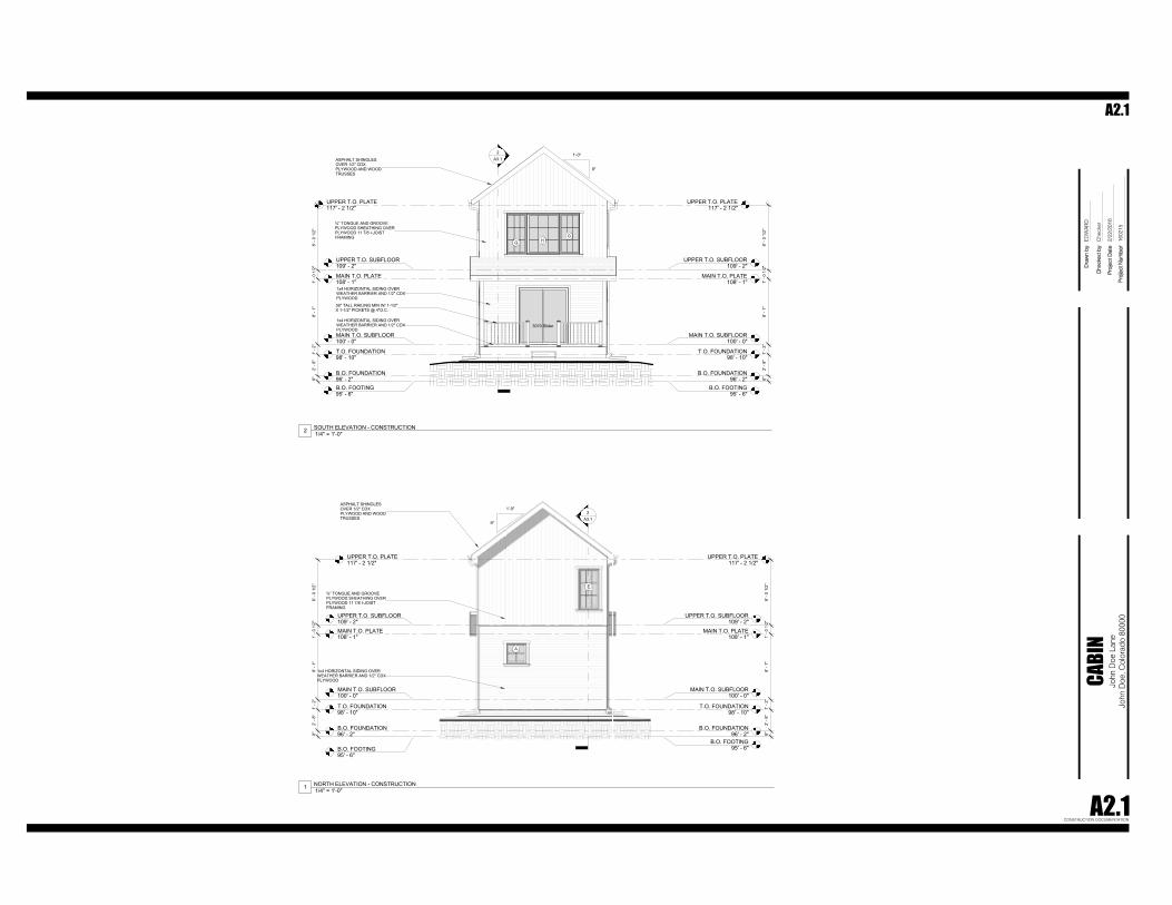
ASPHALT SHINGLESOVER 1/2" CDXPLYWOOD AND WOODTRUSSES
9"
1'-0"
¾” TONGUE AND GROOVEPLYWOOD SHEATHING OVERPLYWOOD 11 7/8 I-JOISTFRAMING
1x4 HORIZONTAL SIDING OVERWEATHER BARRIER AND 1/2" CDXPLYWOOD
MAIN T.O. SUBFLOOR100' - 0"
MAIN T.O. SUBFLOOR100' - 0"
MAIN T.O. PLATE108' - 1"
MAIN T.O. PLATE108' - 1"
T.O. FOUNDATION98' - 10"
T.O. FOUNDATION98' - 10"
B.O. FOUNDATION96' - 2"
B.O. FOUNDATION96' - 2"
8' -
0 1/
2"1'
- 0
1/2"
8' -
1"1'
- 2"
2' -
8"8"
8' -
0 1/
2"1'
- 0
1/2"
8' -
1"1'
- 2"
2' -
8"8"
B.O. FOOTING95' - 6"
B.O. FOOTING95' - 6"
2A3.1
UPPER T.O. SUBFLOOR109' - 2"
UPPER T.O. SUBFLOOR109' - 2"
UPPER T.O. PLATE117' - 2 1/2"
UPPER T.O. PLATE117' - 2 1/2"
GHG
3070 Slider
ASPHALT SHINGLESOVER 1/2" CDXPLYWOOD AND WOODTRUSSES
¾” TONGUE AND GROOVEPLYWOOD SHEATHING OVERPLYWOOD 11 7/8 I-JOISTFRAMING
1x4 HORIZONTAL SIDING OVERWEATHER BARRIER AND 1/2" CDXPLYWOOD
36" TALL RAILING MIN W/ 1-1/2"X 1-1/2" PICKETS @ 4"O.C.
1x4 HORIZONTAL SIDING OVERWEATHER BARRIER AND 1/2" CDXPLYWOOD
9"
1'-0"
Pro
ject
Dat
e
Che
cked
by
Dra
wn
by
Pro
ject
Num
ber
John
Doe
Lan
eJo
hn D
oe, C
olor
ado
8000
0
2/23
/201
6 10
:32:
05 P
M
CABI
N
A2.1CONSTRUCTION DOCUMENTATION
1602
15
ED
WA
RD
Che
cker
2/22
/201
6
A2.1
1/4" = 1'-0"1 NORTH ELEVATION - CONSTRUCTION
1/4" = 1'-0"2 SOUTH ELEVATION - CONSTRUCTION
MAIN T.O. SUBFLOOR100' - 0"
MAIN T.O. SUBFLOOR100' - 0"
MAIN T.O. PLATE108' - 1"
MAIN T.O. PLATE108' - 1"
T.O. FOUNDATION98' - 10" T.O. FOUNDATION
98' - 10"B.O. FOUNDATION96' - 2"
B.O. FOUNDATION96' - 2"
8' -
0 1/
2"1'
- 0
1/2"
8' -
1"1'
- 2"
2' -
8"8"
8' -
0 1/
2"1'
- 0
1/2"
8' -
1"1'
- 2"
2' -
8"8"
B.O. FOOTING95' - 6"
B.O. FOOTING95' - 6"
1A3.1
UPPER T.O. SUBFLOOR109' - 2"
UPPER T.O. SUBFLOOR109' - 2"
UPPER T.O. PLATE117' - 2 1/2"
UPPER T.O. PLATE117' - 2 1/2"
3A3.1
FF
CC
B
C
9" /
1'-0
"
ASPHALT SHINGLESOVER 1/2" CDXPLYWOOD AND WOODTRUSSES
¾” TONGUE AND GROOVEPLYWOOD SHEATHING OVERPLYWOOD 11 7/8 I-JOISTFRAMING
1x4 HORIZONTAL SIDING OVERWEATHER BARRIER AND 1/2" CDXPLYWOOD
MAIN T.O. SUBFLOOR100' - 0"
MAIN T.O. SUBFLOOR100' - 0"
MAIN T.O. PLATE108' - 1"
MAIN T.O. PLATE108' - 1"
T.O. FOUNDATION98' - 10"
T.O. FOUNDATION98' - 10"
B.O. FOUNDATION96' - 2"
B.O. FOUNDATION96' - 2"
8' -
0 1/
2"1'
- 0
1/2"
8' -
1"1'
- 2"
2' -
8"8"
8' -
0 1/
2"1'
- 0
1/2"
8' -
1"1'
- 2"
2' -
8"8"
B.O. FOOTING95' - 6"
B.O. FOOTING95' - 6"
1A3.1
UPPER T.O. SUBFLOOR109' - 2"
UPPER T.O. SUBFLOOR109' - 2"
UPPER T.O. PLATE117' - 2 1/2"
UPPER T.O. PLATE117' - 2 1/2"
3A3.1
D
D
D
C C C
9" /
1'-0
"
4"
1'-0"
ASPHALT SHINGLESOVER 1/2" CDXPLYWOOD AND WOODTRUSSES
¾” TONGUE AND GROOVEPLYWOOD SHEATHING OVERPLYWOOD 11 7/8 I-JOISTFRAMING
1x4 HORIZONTAL SIDING OVERWEATHER BARRIER AND 1/2" CDXPLYWOOD
Pro
ject
Dat
e
Che
cked
by
Dra
wn
by
Pro
ject
Num
ber
John
Doe
Lan
eJo
hn D
oe, C
olor
ado
8000
0
2/23
/201
6 10
:32:
10 P
M
CABI
N
A2.2CONSTRUCTION DOCUMENTATION
1602
15
ED
WA
RD
LMC
2/22
/201
6
A2.2
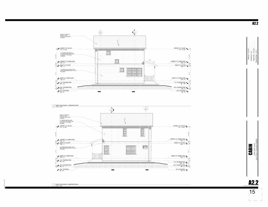
1/4" = 1'-0"1 EAST ELEVATION - CONSTRUCTION
1/4" = 1'-0"2 WEST ELEVATION - CONSTRUCTION
MAIN T.O. SUBFLOOR100' - 0"
MAIN T.O. SUBFLOOR100' - 0"
MAIN T.O. PLATE108' - 1"
MAIN T.O. PLATE108' - 1"
T.O. FOUNDATION98' - 10" T.O. FOUNDATION
98' - 10"B.O. FOUNDATION96' - 2"
B.O. FOUNDATION96' - 2"
8' -
0 1/
2"1'
- 0
1/2"
8' -
1"1'
- 2"
2' -
8"8"
8' -
0 1/
2"1'
- 0
1/2"
8' -
1"1'
- 2"
2' -
8"8"
B.O. FOOTING95' - 6"
B.O. FOOTING95' - 6"
1A3.1
UPPER T.O. SUBFLOOR109' - 2"
UPPER T.O. SUBFLOOR109' - 2"
UPPER T.O. PLATE117' - 2 1/2"
UPPER T.O. PLATE117' - 2 1/2"
3A3.1
FF
CC
B
C
9" /
1'-0
"
ASPHALT SHINGLESOVER 1/2" CDXPLYWOOD AND WOODTRUSSES
¾” TONGUE AND GROOVEPLYWOOD SHEATHING OVERPLYWOOD 11 7/8 I-JOISTFRAMING
1x4 HORIZONTAL SIDING OVERWEATHER BARRIER AND 1/2" CDXPLYWOOD
MAIN T.O. SUBFLOOR100' - 0"
MAIN T.O. SUBFLOOR100' - 0"
MAIN T.O. PLATE108' - 1"
MAIN T.O. PLATE108' - 1"
T.O. FOUNDATION98' - 10"
T.O. FOUNDATION98' - 10"
B.O. FOUNDATION96' - 2"
B.O. FOUNDATION96' - 2"
8' -
0 1/
2"1'
- 0
1/2"
8' -
1"1'
- 2"
2' -
8"8"
8' -
0 1/
2"1'
- 0
1/2"
8' -
1"1'
- 2"
2' -
8"8"
B.O. FOOTING95' - 6"
B.O. FOOTING95' - 6"
1A3.1
UPPER T.O. SUBFLOOR109' - 2"
UPPER T.O. SUBFLOOR109' - 2"
UPPER T.O. PLATE117' - 2 1/2"
UPPER T.O. PLATE117' - 2 1/2"
3A3.1
D
D
D
C C C
9" /
1'-0
"
4"
1'-0"
ASPHALT SHINGLESOVER 1/2" CDXPLYWOOD AND WOODTRUSSES
¾” TONGUE AND GROOVEPLYWOOD SHEATHING OVERPLYWOOD 11 7/8 I-JOISTFRAMING
1x4 HORIZONTAL SIDING OVERWEATHER BARRIER AND 1/2" CDXPLYWOOD
Pro
ject
Dat
e
Che
cked
by
Dra
wn
by
Pro
ject
Num
ber
John
Doe
Lan
eJo
hn D
oe, C
olor
ado
8000
0
2/23
/201
6 10
:32:
10 P
M
CABI
N
A2.2CONSTRUCTION DOCUMENTATION
1602
15
ED
WA
RD
LMC
2/22
/201
6
A2.2
1/4" = 1'-0"1 EAST ELEVATION - CONSTRUCTION
1/4" = 1'-0"2 WEST ELEVATION - CONSTRUCTION
15
MAIN T.O. SUBFLOOR100' - 0"
MAIN T.O. SUBFLOOR100' - 0"
MAIN T.O. PLATE108' - 1"
MAIN T.O. PLATE108' - 1"
T.O. FOUNDATION98' - 10"
T.O. FOUNDATION98' - 10"
B.O. FOUNDATION96' - 2"
B.O. FOUNDATION96' - 2"
B.O. FOOTING95' - 6"
B.O. FOOTING95' - 6"
8' -
0 1/
2"1'
- 0
1/2"
8' -
1"1'
- 2"
2' -
8"8"
8' -
0 1/
2"1'
- 0
1/2"
8' -
1"1'
- 2"
2' -
8"8"
2A3.1
UPPER T.O. SUBFLOOR109' - 2"
UPPER T.O. SUBFLOOR109' - 2"
UPPER T.O. PLATE117' - 2 1/2"
UPPER T.O. PLATE117' - 2 1/2"
PRE-ENGINEERED TRUSSES@ 24" O.C. (BY OTHERS)
9"
1'-0"
MAIN T.O. SUBFLOOR100' - 0"
MAIN T.O. SUBFLOOR100' - 0"
MAIN T.O. PLATE108' - 1"
MAIN T.O. PLATE108' - 1"
T.O. FOUNDATION98' - 10"
T.O. FOUNDATION98' - 10"
B.O. FOUNDATION96' - 2"
B.O. FOUNDATION96' - 2"
B.O. FOOTING95' - 6"
B.O. FOOTING95' - 6"
1A3.1
8' -
0 1/
2"1'
- 0
1/2"
8' -
1"1'
- 2"
2' -
8"8"
8' -
0 1/
2"1'
- 0
1/2"
8' -
1"1'
- 2"
2' -
8"8"
UPPER T.O. SUBFLOOR109' - 2"
UPPER T.O. SUBFLOOR109' - 2"
UPPER T.O. PLATE117' - 2 1/2"
UPPER T.O. PLATE117' - 2 1/2"
3A3.1
PRE-ENGINEERED TRUSSES@ 24" O.C. (BY OTHERS)
MAIN T.O. SUBFLOOR100' - 0"
MAIN T.O. PLATE108' - 1"
T.O. FOUNDATION98' - 10"
B.O. FOUNDATION96' - 2"
B.O. FOOTING95' - 6"
UPPER T.O. SUBFLOOR109' - 2"
UPPER T.O. PLATE117' - 2 1/2" 15
" HEE
L H
EIG
HT
MIN
.
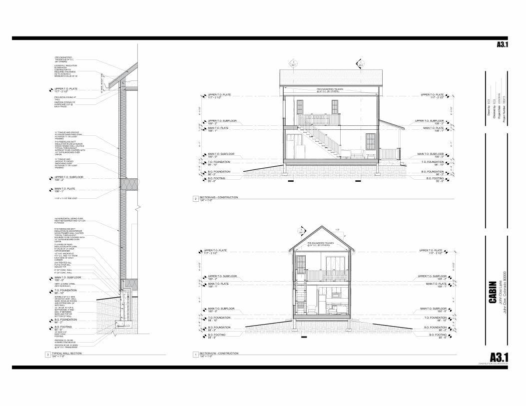
PRE-ENGINEEREDTRUSSES @ 24" O.C.(BY OTHERS)
LOOSE FILL INSULATIONBLOWN-IN BYCONTRACTOR TOREQUIRED THICKNESSAS TO ACHEIVE AMINIMUM R-VALUE OF 38
PROVIDE BLOCKING ATTAILSSIMPSON STRONG-TIEHURRICANE CLIP @EACH TRUSS
¾” TONGUE AND GROOVEPLYWOOD SHEATHING OVERPLYWOOD 11 7/8 I-JOISTFRAMINGR19 FIBERGLASS BATTINSULATION IN 2X6 EXTERIORWOOD FRAMED WALL CAVITIESTYPICAL THROUGHOUT.INTERIOR TO BE COVERED WITH1/2" GYPSUM BOARD OVERVAPOR.
¾” TONGUE ANDGROOVE PLYWOODSHEATHING OVERPLYWOOD 11 7/8 I-JOISTFRAMING
1-1/8" x 11-7/8" RIM JOIST
1x4 HORIZONTAL SIDING OVERWEATHER BARRIER AND 1/2" CDXPLYWOOD
R19 FIBERGLASS BATTINSULATION IN 2X6 EXTERIORWOOD FRAMED WALL CAVITIESTYPICAL THROUGHOUT.INTERIOR TO BE COVERED WITH1/2" GYPSUM BOARD OVERVAPOR.2 LAYERS OF RIGIDINSULATION WITH A MIN.R-VALUE OF 21 OVERVAPOR BARRIER1/2" X10" ANCHOR AT4'-0" O.C. AND 1'-0" FROMEACH SIDE OF EACHCORNER2X6 TREATED SILLPLATE OVER SILLSEALER TYP.8" CIP CONC. WALL8" CIP CONC. WALL
VERT. & HORIZ. STEEL(SEE SCHEDULE)
18" WIDE X 8"DEEP CONC.FOOTING
DOWELS 32" O.C. MAXOR MATCH VERT. WALLBARD, BEND AS SHOWNAND EXTEND MIN. 24"INTO WALL(2) - #5 GR. 40 TOP &BOTTOM MIN. 3" ANDMAX. 6" BETWEENBARS AND TOP ORBOTTOM OF WALL
PROVIDE [3] - #4 GR.40 BARS CONTINUOUSPROVIDE #4 GR. 40 BARS@ 24" O.C. TRANSVERSE
Pro
ject
Dat
e
Che
cked
by
Dra
wn
by
Pro
ject
Num
ber
John
Doe
Lan
eJo
hn D
oe, C
olor
ado
8000
0
2/23
/201
6 10
:32:
11 P
M
CABI
N
A3.1CONSTRUCTION DOCUMENTATION
1602
15
EC
S
EC
S
2/22
/201
6
A3.1
1/4" = 1'-0"1 SECTION E/W - CONSTRUCTION
1/4" = 1'-0"2 SECTION N/S - CONSTRUCTION
3/4" = 1'-0"3 TYPICAL WALL SECTION
3' -
0"1'
- 2"
4"
1 1/
2"
2' -
10 1
/2"
2' - 0"2' - 6"1' - 6"2' - 0"
2' -
0"5'
- 6"
2' - 0"2' - 6"1' - 6 1/2"
Pro
ject
Dat
e
Che
cked
by
Dra
wn
by
Pro
ject
Num
ber
John
Doe
Lan
eJo
hn D
oe, C
olor
ado
8000
0
2/23
/201
6 10
:32:
12 P
M
CABI
N
A4.1CONSTRUCTION DOCUMENTATION
1602
15
EC
S
EC
S
2/22
/201
6
A4.1
1 1/2" = 1'-0"1 INTERIOR ELEVATION KITCHEN
17

Experiential Bridge
Zeus’ Bolt
This bridge was designed with the purpose of three users: street performers, par-core enthusiasts, and fishermen. The bridge is built on 60 and 120 degree angles. The bridge has A stage for the street performers. There are two cut out spot at the obtuse angels for fishermen. The par-core users have the most. The trellis can be used as monkey bars, the retaining walls off the bridge leadingup to the bridge are balance beams

19
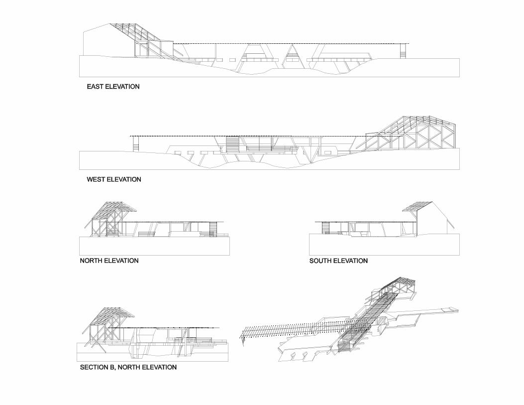
EAST ELEVATION
WEST ELEVATION
NORTH ELEVATION SOUTH ELEVATION
SECTION A, WEST ELEVATION
SECTION B, NORTH ELEVATION
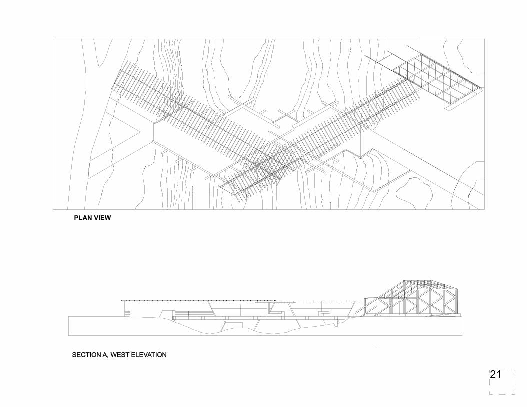
PLAN VIEW
SECTION A, WEST ELEVATION
SECTION B, NORTH ELEVATION
PLAN VIEW
21

Rendered Elevations
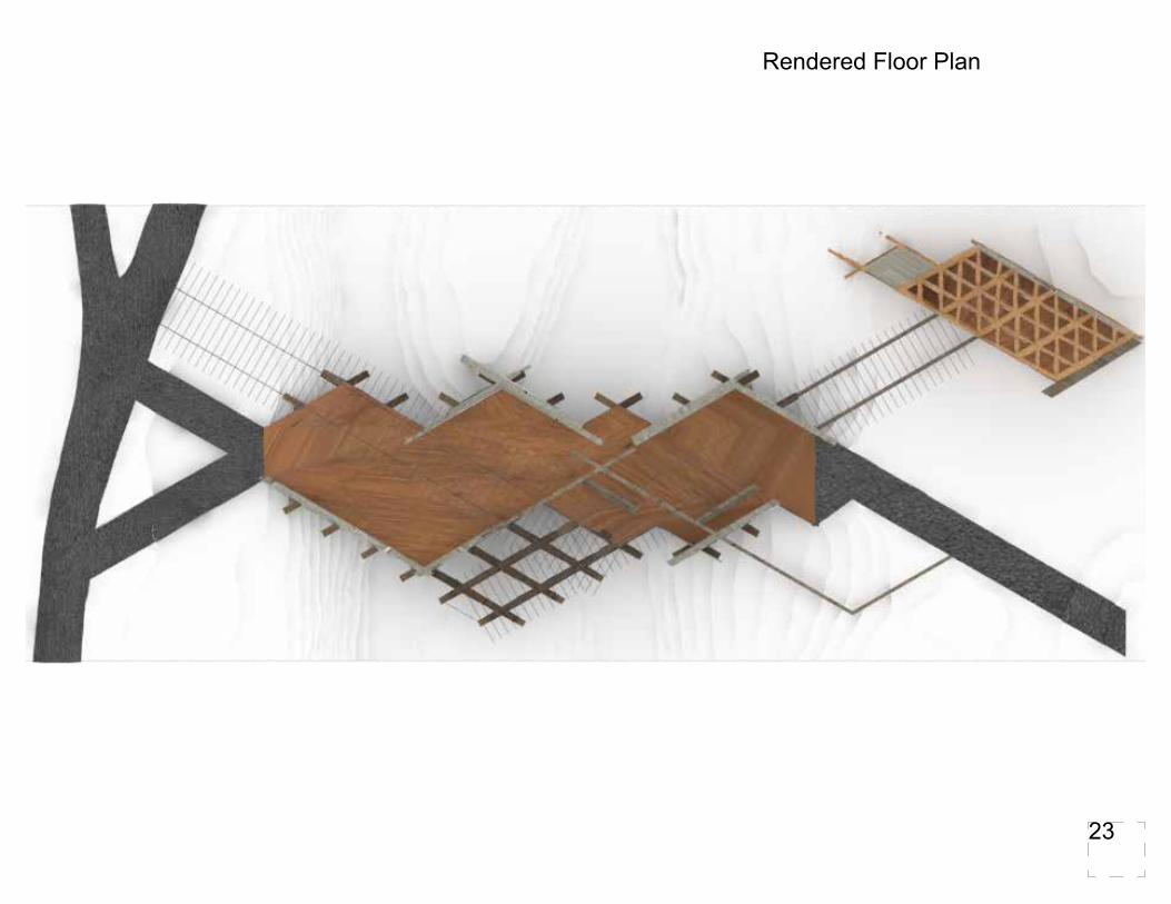
Rendered Floor Plan
23
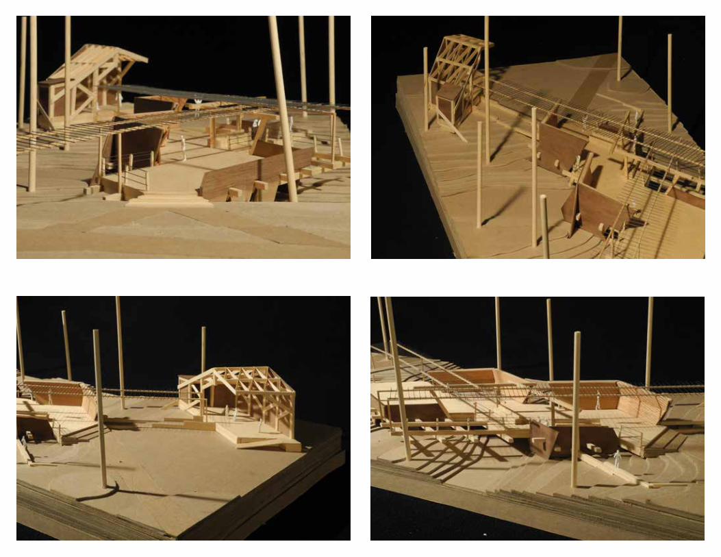
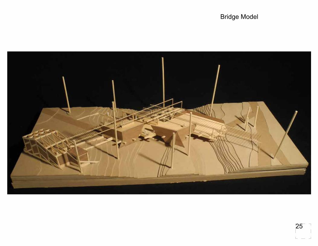
Bridge Model
25

Study Abroad
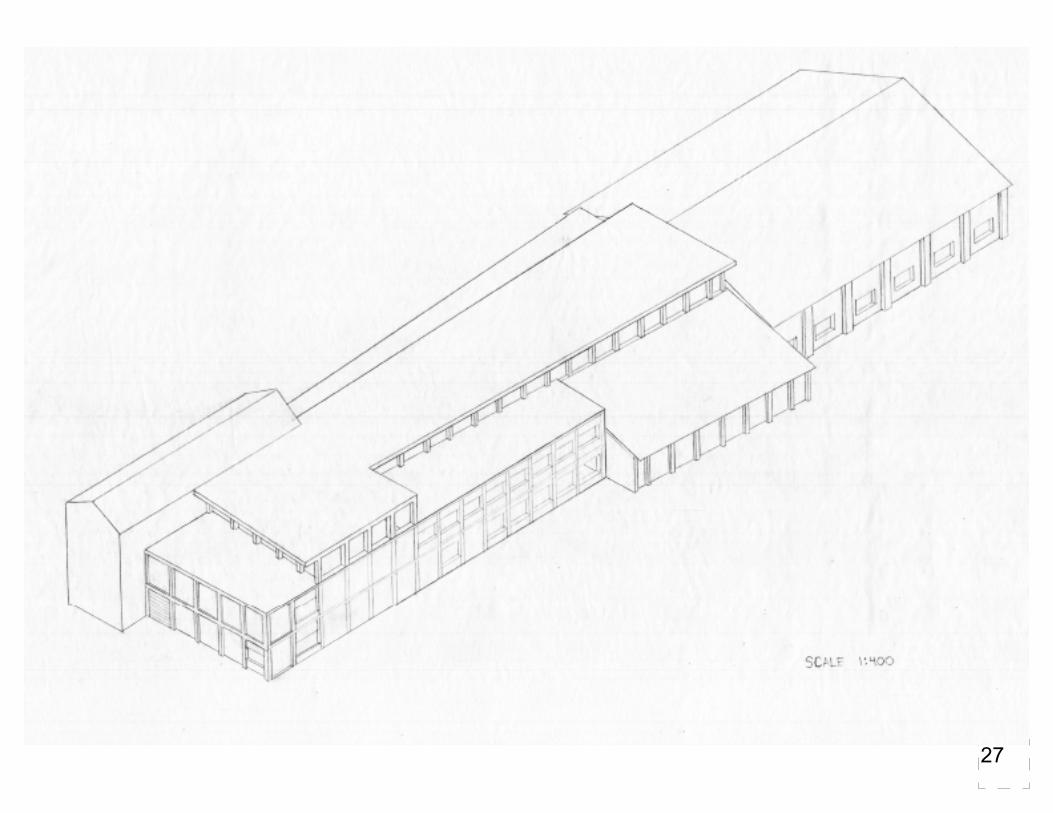
Popes’ Pub
This is a 14,000 sqft brewery located in Rome spanning parallel to the Tiber River at Porta Portese. The Brewery is re-purposing two of the historical buildings in this area, the Granary and the Arsenale. This area used to be the old port city and storage of grains for the pope. My objective was to re-purpose the historic buildings. I turned the Arsenale into a bar/restaurant and the Granary as a graining room and malt production. This would be one of the first large scale breweries in Rome. There aren’t any brewery’s in Rome because the water is too hard. For this to work there would need to water filtration system that changes the pH and mineral level to make the beer have a better taste.
27
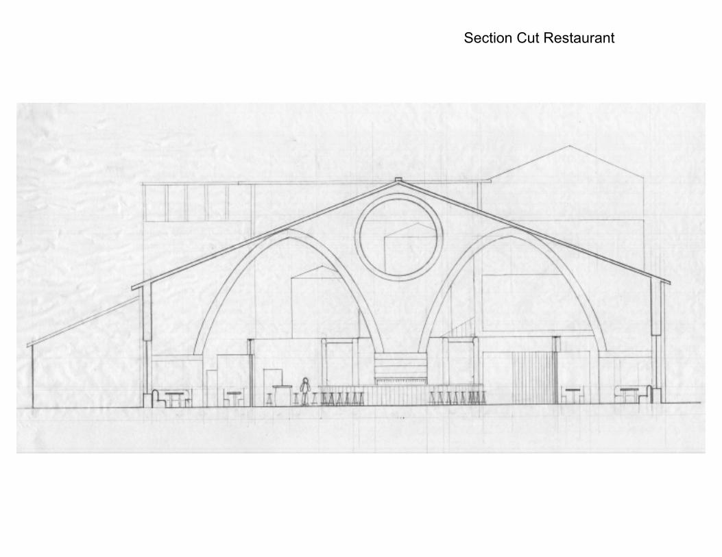
Section Cut Restaurant
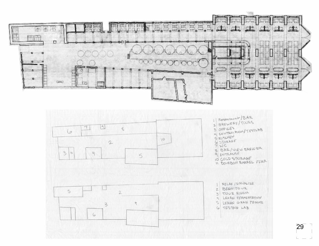
29

Axon of Bar
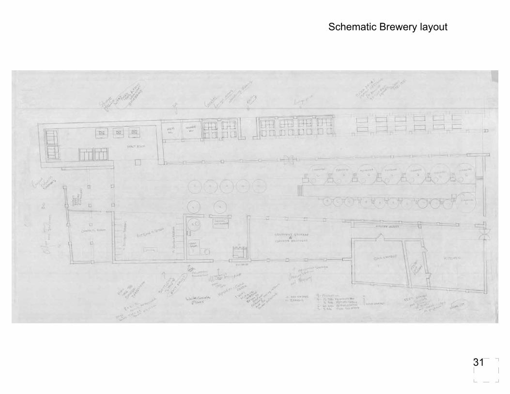
Schematic Brewery layout
31


Modular Chair
Sukasi
This chair has a rotating pivot point under where your knees would go. The chair/table rotates 90 degrees and there is a pin that locks and holds the chair, allowing it to become a table. If two chairs are rotated, they connect at the top/middle with three finger joints to secure them in place.
33
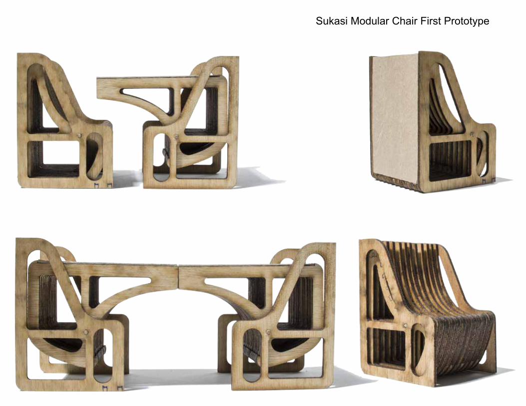
Sukasi Modular Chair First Prototype
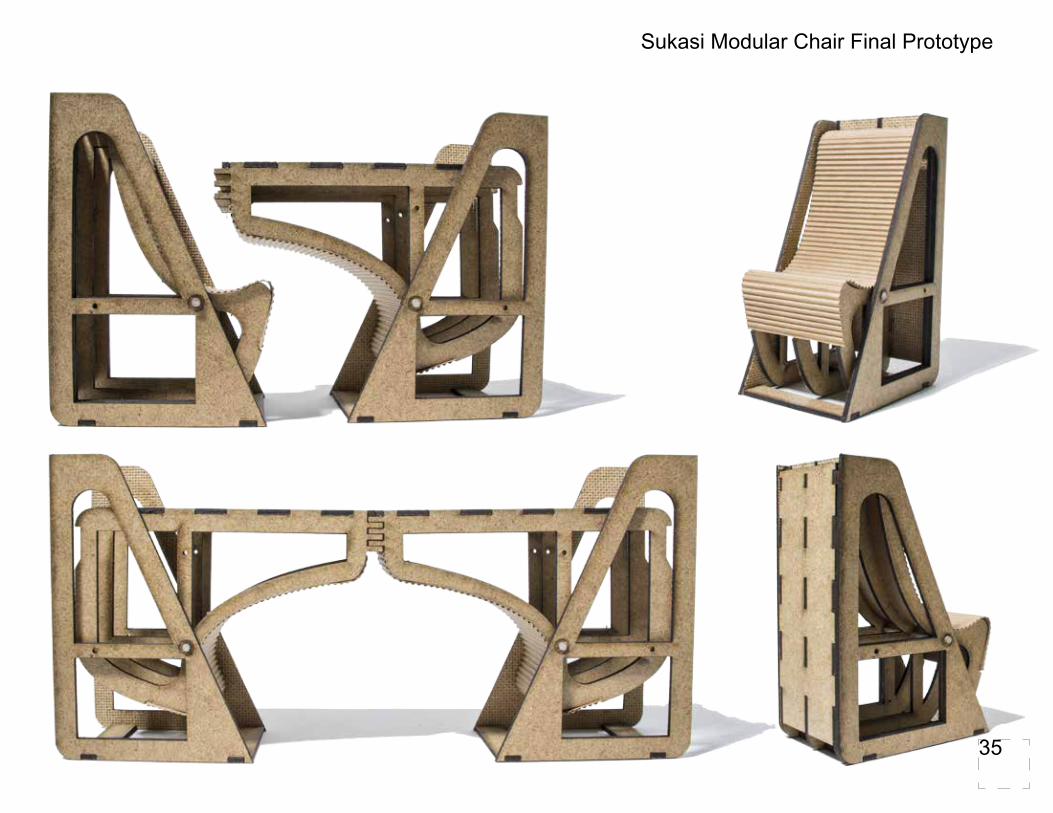
Sukasi Modular Chair Final Prototype
35

Freedom of Speech: Part One
Heuristic SculptureLead Wings
When thinking about how freedom is represented around the world the idea of oppression came to mind. The chain/wire is restricts the bird from being able to do what it naturally should, fly. Much of the world has been held back and oppressed from war, corruption, drugs, and lies.

Heuristic Model Freedom of Speech
37

Freedom of Speech: Part Two
Charlie Hebdo Free Speech PavilionBee Breeder Competition
This pavilion was inspired by my idea from the Heuristic sculpture. The ribbon on the exterior resembles a cage. A person is supposed to feel confined and trapped, like being in a prison. Many people around the world are restricted and censored. Inside, there are four gallery rooms. Each room represents a different degree of censorship that can be found around the world.
39
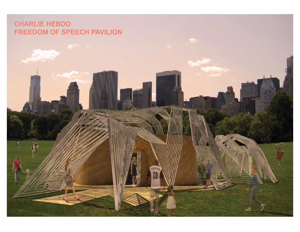
CHARLIE HEBDOFREEDOM OF SPEECH PAVILION

4. ELEVATOR
1. ENTRANCE/ EXIT2. RECEPTION3. ADVICE & SUPPORT
5. CONFERENCE6. WORKSHOP7. CAFE8. GLASS ATRIUM
11. GALLERY TWO SOME CENSORSHIP
9. COURT YARD10. GALLERY ONE NO CENSORSHIP
12. GALLERY THREE UNDER SURVEILLANCE 13. GALLERY FOUR HEAVILY CENSORED14. DECK LOOKING OVER COURT YARD15. DECK LOOKING AT RIBBON
2.
3.
6.7.
13.
12. 11.
10. 15.
14.
8.
9.
5.
4.
4.
1.
LEGEND:
41
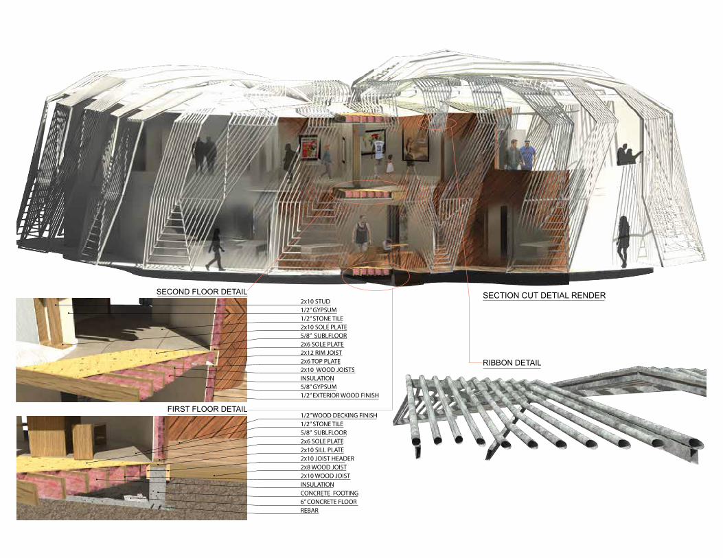
2x6 SOLE PLATE
2X10 WOOD JOIST
1/2” WOOD DECKING FINISH
INSULATIONCONCRETE FOOTING
2x10 SILL PLATE
2X8 WOOD JOIST2X10 JOIST HEADER
1/2” STONE TILE
REBAR
5/8” SUBLFLOOR
6” CONCRETE FLOOR
2x10 SOLE PLATE 1/2” STONE TILE
5/8” GYPSUM
2X12 RIM JOIST
INSULATION2X10 WOOD JOISTS
2X10 STUD1/2” GYPSUM
5/8” SUBLFLOOR2X6 SOLE PLATE
1/2” EXTERIOR WOOD FINISH
2X6 TOP PLATE RIBBON DETAIL
FIRST FLOOR DETAIL
SECOND FLOOR DETAIL SECTION CUT DETIAL RENDER
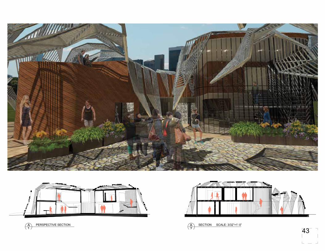
A1
PERSPECTIVE SECTION A2
SECTION SCALE: 3/32”=1’-0”
43

Thank You,
Edward Sweeney


