
SANDBLAST CABINET
SBC990
OPERATING AND MAINTENANCE INSTRUCTIONS

Page 1 of 12
CONTENTS
1. TECHNICAL SPECIFICATIONS Pg 1
2. IMPORTANT WARNING Pg 2
3. IMPORTANT NOTICE Pg 2-3
4. ASSEMBLY INSTRUCTIONS Pg 3-6
5. OPERATION INSTRUCTIONS Pg 3-6
6. MAINTAIN SUCTION EFFICENCY WITH SIMPLE STEPS Pg 6-7
7. SUPPLY AIR PIPE SIZE Pg 7-8
8. CABINET PARTS DIAGRAM&PARTS LIST Pg 9-12
TECHNICAL SPECIFICATIONS :
Rating: 110~120V, 60 Hz (220~240V,50Hz), 1210W
Maximum Work Pressure 125PSI (8.6Bar)
Air Consumption: 24CFM@125PSI (680L/Min)
Work Light:
Fluorescent Light: 4pcs
Each Dimension:φ16x890
Each Rating:110~120V,60Hz( 220~240V,50Hz),26W
Motor Rating: 110~120V, 60 Hz (220~240V, 50Hz), 1100W
Overall Dimensions: W52-3/8″x D48-4/5″x H69-3/5″(133x124x177cm)
Net Weight: 160Kg
Gross Weight: 198Kg

Page 2 of 12
IMPORTANT WARNING
READ ALL INSTRUCTIONS BEFORE USING THIS EQUIPMENT.
SAVE THESE INSTRUCTIONS FOR FUTURE REFERENCE.
Due To Continuing Improvement, Actual Product May Differ Slightly From Product Described Herein.
Remember
1. START UP PREPARATIONS:
- The I.D of air line should be more than 8mm (0.3”). ALL Hoses Should Be Rated At Least 125psi
(8.6bar) And An Isolation valve should be installed so that supply air can be turned off and then
disconnected from sandblaster cabin for servicing.
- Supply air should be dry and clean from oil and other contaminants. (i.e. use air dryer,
coalescent filter, or moisture separator as needed.)
- Blast machine must be grounded to avoid shock..
- Electric extension cords should be three wire grounded (wire size can not be smaller than
3x1.5MM2 ).
2. operator’s responsibilities before starting: - inspect fittings and hoses for damage and water
- Check the seal on all doors. only operate the blast cabinet with all doors securely closed and
dust collection system running.
- Clean dust from dust collector and clean filter as needed.
3. caution
- watch for silicosis (form dust created when using silica sand as a blast media) or toxic dust
hazard. do not use media containing free silica
- unless special specified, working pressure of blast cabinet and related components must not
exceed 125PSI
- keep blast nozzle controlled and aimed at the work.
4. maintenance
- keep your machine in good repair. Use original parts and do not substitute or modify original
supplied items.
IMPORTANT NOTICE
To distributors, purchasers and end users of using this product.
The provided information described and illustrated in this material is intended for experienced,
knowledgeable users of abrasive blasting equipment and supplies (products).
The products described in this material may be combined as determined solely by the user in a variety of
way and purposes. However not representations are made as to intended use, performance standards,
engineering suitability, safe practices or compliance with government regulation and laws that apply to
these products, products of others, or a combination of various products of third parties, and a
combination of various products chosen by the user or others. It is the responsibility of the users of these
products, products of third parties, and a combination of various products, to exercise caution and
familiarize themselves with all applicable laws, government regulations and safety requirements.

Page 3 of 12
Nor are representations made or intended to the useful life, maintenance cycles, efficiency or
performance of the referenced products of any combination of products.
This material must not be used for estimating purpose. Production rates, labor performance or surface
finished are the sole responsibility or the user based on the users expertise, experience and knowledge
of industry variables.
It is the responsibility of the user to insure that proper and comprehensive training of operators has been
performed and all environmental and safety precautions observed.
We provides a variety of excellent products to the surface preparation industry, and we are confident
that all proficient users, operators and contractors in this industry will continue to use our products in a
safe and knowledge manner.
ASSEMBLY INSTRUCTIONS

Page 4 of 12
STEP <1>
1.Please upend the bracket (#8), use M8*20 hex bolt(match faced washers, spring washers) to pass leg
A (3pcs), leg B (#10)(1PC), then mount on the bracket as figure showed. Please take care the deposited
position & direction of leg B(#10)
2.Please use M8*20 hex bolt and faced washers, spring washers to pass leg reinforce 1,2. then mount
on the bracket as figure showed.
STEP<2>:
Please place assembling parts of Step <1> to position as figure, then put the big funnel in the middle.
Please note: The front big funnel should be put to face leg B.

Page 5 of 12
Step<3>:
1.Please place the upper cabinet on the assembled Step<2> as figure. Please notice that front of upper
cabinet should be put to face leg B.
2.Opening the double folded door, combine the upper cabinet, big funnel & bracket in one whole by
22pcs M6*16 round head screws and faced washers.
Step<4>:
1. Taking 4pcs M6*12 big brazier head screws, & M6 flange nuts to mount the dust collector at the
backboard of upper cabinet. Electric Wire of assembled dust collector plug into the socket of switch box
through the slot of right board of upper cabinet,
2. Mounting pressure regulating valve etc. on the leg B. & connecting the orange air hose of foot valve
switch to the side hole of right big funnel, then connect it to the sandblast gun.

Page 6 of 12
3. Please place the left / right grid in the upper cabinet.
4. Remove the sandblaster to the right position by forklift, then remove the reinforce of front leg.
OPERATING INSTRUCTIONS
1. preparing parts for blasting
all parts processed must be free of oil, grease and moisture. Make sure parts are dry before putting
into the cabinet for cleaning.
2. air pressure
operating pressure: from 50 to 80 psi (pounds per square inch)(higher pressure (up to 125 can be
used, but this breaks down some types for media’s prematurely).(ex. glass bead) - set air pressure to 80 psi. most parts for blast cleaning can be blasted at 80 psi. for light gauge
steel, aluminum, and other more delicate parts, start at lower pressure and gradually increase
the pressure until the desired finish is achieved.
Warning
Do not connect to high pressure bottle gas, rupture and explosion can occur.
3. gun angle and distance
direct gun at parts at 45-60 degree angle with ricochet towards the back of the cabinet. Do not hold
gun at 90 degree angle to parts being processed. This will cause the media blast to bounce back
into the blast stream and slow blasting action. Also 90 degree angle will cause excessive wear on
gun and viewing window. Hold gun approximately 6 inches form parts being blasted.
Warning:
Gun must always be pointed away from the operator and towards items being processed. Never
blast with any of the cabinet doors open. While loading and unloading. No one should be at the
operator station. At the front of the blast cabinet.
- cabinets are available with safety doors so that the gun cannot be operated unless the doors
are closed. Contact your local distributer for further information.
4. media
- media should be of good quality and dry. Moisture will cause the media not flow and will clog
metering valve and hopper.
5. nozzle size
- by changing to the next larger size of nozzle ,. Production can increase significantly. Lager
size nozzles produce a large cleaning pattern. This, however, requires more air (your
compressor must be able to provide this)
MAINTENANCE INSTRUCTIONS
1. blasting gun
- after 10-12 hours of blasting time, the nozzle should be checked. If it shows uneven wear it
should be turned 1/4 turn every 10 hours of use.
2. caking of media
- media caking is caused by moisture in the air supply of from oily and greasy parts. If this is not
Page 7 of 12
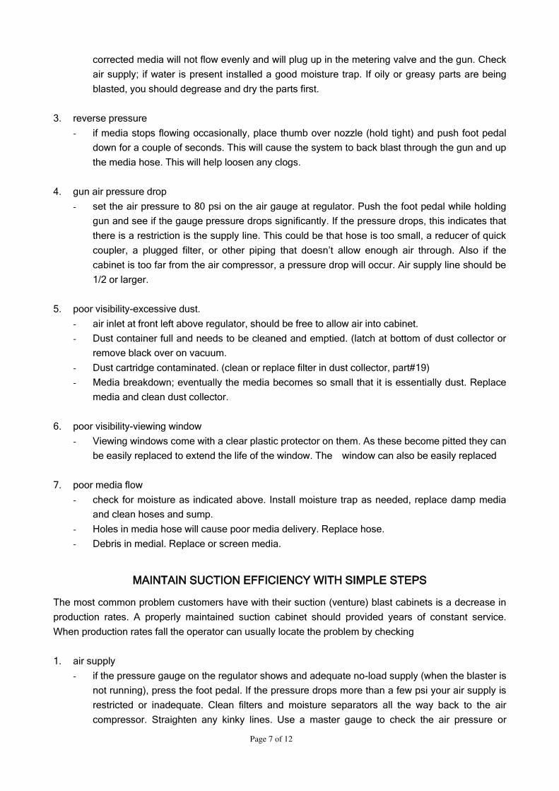
corrected media will not flow evenly and will plug up in the metering valve and the gun. Check
air supply; if water is present installed a good moisture trap. If oily or greasy parts are being
blasted, you should degrease and dry the parts first.
3. reverse pressure
- if media stops flowing occasionally, place thumb over nozzle (hold tight) and push foot pedal
down for a couple of seconds. This will cause the system to back blast through the gun and up
the media hose. This will help loosen any clogs.
4. gun air pressure drop
- set the air pressure to 80 psi on the air gauge at regulator. Push the foot pedal while holding
gun and see if the gauge pressure drops significantly. If the pressure drops, this indicates that
there is a restriction is the supply line. This could be that hose is too small, a reducer of quick
coupler, a plugged filter, or other piping that doesn’t allow enough air through. Also if the cabinet is too far from the air compressor, a pressure drop will occur. Air supply line should be
1/2 or larger.
5. poor visibility-excessive dust.
- air inlet at front left above regulator, should be free to allow air into cabinet.
- Dust container full and needs to be cleaned and emptied. (latch at bottom of dust collector or
remove black over on vacuum.
- Dust cartridge contaminated. (clean or replace filter in dust collector, part#19)
- Media breakdown; eventually the media becomes so small that it is essentially dust. Replace
media and clean dust collector.
6. poor visibility-viewing window
- Viewing windows come with a clear plastic protector on them. As these become pitted they can
be easily replaced to extend the life of the window. The window can also be easily replaced
7. poor media flow
- check for moisture as indicated above. Install moisture trap as needed, replace damp media
and clean hoses and sump.
- Holes in media hose will cause poor media delivery. Replace hose.
- Debris in medial. Replace or screen media.
MAINTAIN SUCTION EFFICIENCY WITH SIMPLE STEPS
The most common problem customers have with their suction (venture) blast cabinets is a decrease in
production rates. A properly maintained suction cabinet should provided years of constant service.
When production rates fall the operator can usually locate the problem by checking
1. air supply
- if the pressure gauge on the regulator shows and adequate no-load supply (when the blaster is
not running), press the foot pedal. If the pressure drops more than a few psi your air supply is
restricted or inadequate. Clean filters and moisture separators all the way back to the air
compressor. Straighten any kinky lines. Use a master gauge to check the air pressure or
Page 8 of 12
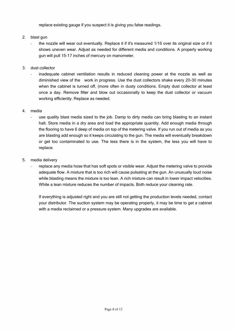
replace existing gauge if you suspect it is giving you false readings.
2. blast gun
- the nozzle will wear out eventually. Replace it if it's measured 1/16 over its original size or if it
shows uneven wear. Adjust as needed for different media and conditions. A properly working
gun will pull 15-17 inches of mercury on manometer.
3. dust collector
- inadequate cabinet ventilation results in reduced cleaning power at the nozzle as well as
diminished view of the work in progress. Use the dust collectors shake every 20-30 minutes
when the cabinet is turned off, (more often in dusty conditions. Empty dust collector at least
once a day. Remove filter and blow out occasionally to keep the dust collector or vacuum
working efficiently. Replace as needed.
4. media
- use quality blast media sized to the job. Damp to dirty media can bring blasting to an instant
halt. Store media in a dry area and load the appropriate quantity. Add enough media through
the flooring to have 6 deep of media on top of the metering valve. If you run out of media as you
are blasting add enough so it keeps circulating to the gun. The media will eventually breakdown
or get too contaminated to use. The less there is in the system, the less you will have to
replace.
5. media delivery
- replace any media hose that has soft spots or visible wear. Adjust the metering valve to provide
adequate flow. A mixture that is too rich will cause pulsating at the gun. An unusually loud noise
while blasting means the mixture is too lean. A rich mixture can result in lower impact velocities.
While a lean mixture reduces the number of impacts. Both reduce your cleaning rate.
If everything is adjusted right and you are still not getting the production levels needed, contact
your distributor. The suction system may be operating properly, it may be time to get a cabinet
with a media reclaimed or a pressure system. Many upgrades are available.

Page 9 of 12
PARTS DIAGRAM-1

Page 10 of 12
PARTS DIAGRAM-2

Page 11 of 12
PARTS LISTING
ITEM# DESCRIPTION QUANTITY
1 Upper cabinet 1
2 Round head cross screws
(matched washers) 22
3 Suction sand hose 1
4 Left grid 1
5 Right grid 1
6 Sealing tape 1
7 Big funnel 1
8 Bracket 1
9 M8*20 32
10 Leg B 1
11 Permanent seat of pneumatic device 1
12 Pressure gauge/
Pressure regulating valve Each 1
13 Assembled latches 3
14 Welded cover board for falling sand 1
15 Pneumatic device of foot pedal 1
16 Leg reinforces 1 2
17 Leg reinforces 2 2
18 Legs A 3
19 Dust collector 1
20 M6*32 round head screws 12
21 Bracket of viewing window 1
22 Glass board of viewing window 1
23 Glass of viewing window 1
24 PE film of viewing window 1
25 Sealing tape of viewing window 1
26 Rubber seal strip of front opening doorframe 1
27 Bracket of top light 1
28 Seat of fluorescent lamp/ lamps 4pcs 1
29 Glass of light window 1
30 PE film of light window 1
31 Rubber seal strip of light window 1
32 sand boards 2
33 Main body of upper cabinet 1
34 Main support poles 2
35 Support pole of air springs 2
36 Plastic slot board of wire 1
37 Front door latch 2
38 Latch seats 2
39 Rack board 1
40 grips (similar with PSJ of vacuum model ) 2
41 Elements of big hoops 2
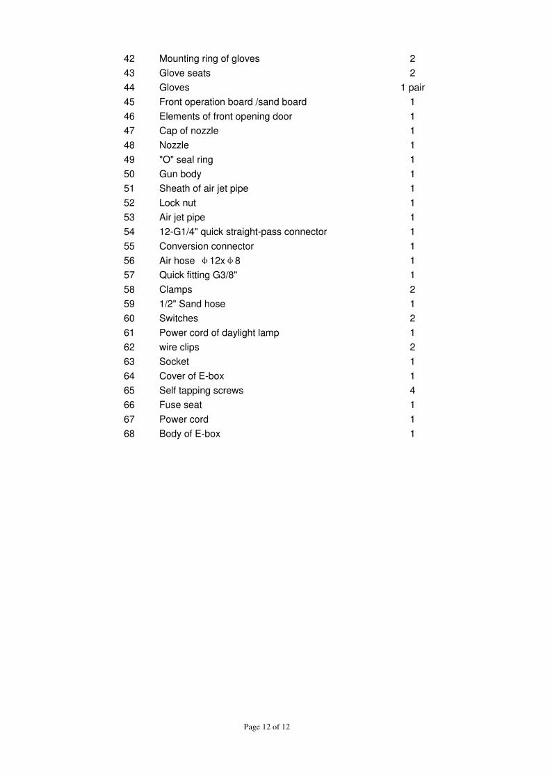
Page 12 of 12
42 Mounting ring of gloves 2
43 Glove seats 2
44 Gloves 1 pair
45 Front operation board /sand board 1
46 Elements of front opening door 1
47 Cap of nozzle 1
48 Nozzle 1
49 "O" seal ring 1
50 Gun body 1
51 Sheath of air jet pipe 1
52 Lock nut 1
53 Air jet pipe 1
54 12-G1/4" quick straight-pass connector 1
55 Conversion connector 1
56 Air hose φ12xφ8 1
57 Quick fitting G3/8" 1
58 Clamps 2
59 1/2" Sand hose 1
60 Switches 2
61 Power cord of daylight lamp 1
62 wire clips 2
63 Socket 1
64 Cover of E-box 1
65 Self tapping screws 4
66 Fuse seat 1
67 Power cord 1
68 Body of E-box 1


