
SSSaaammmpppllleee CCChhhaaapppttteeerrr Special Deep Foundation – Compendium Volume II Methods and Equipment – Drilling rigs and duty cycle crawler cranes Editors: Liebherr Nenzig GmbH Copyright © 2009 Liebherr Nenzig GmbH ISBN: 978-3-433-02932-9
Wilhelm Ernst & Sohn Verlag für Architektur und technische Wissenschaften GmbH & Co. KG Rotherstraße 21, 10245 Berlin Deutschland www.ernst-und-sohn.de

Kelly drilling
�
1 General
Kelly drilling.is.a.dry.rotary.drilling.method.for.producing.large.diameter.boreholes.(minimum.approx..50.cm)...It.is.the.most.widely.spread.large.diameter.drilling.method.in.special.deep.foundation..Using.this.method,.cased.and.uncased.drilling.is.carried.out..
Thanks.to.their.special.torsion-resistant.leaders.the.Liebherr.LB.drilling.rigs.are.especially.well.suited.for.this.method.as.high.rotary.forces.(torques).can.be.applied.to.the.drilling.tool..
Kelly.drilling.is.exclusively.used.for.producing.large.diameter.boreholes.by.rotary.drilling,.namely.for.the.following.applications.(products):
-..large.diameter.drilled.piles
-..boreholes.for.installing.steel.beam.profiles.and.steel.pipes
-..boreholes.for.sand.and.gravel.piles
-..soil.exchange.drilling
-..well.drilling
The.method.gets.its.name.from.the.use.of.a.specially.designed.drilling.rod,.the.“Kelly bar”..This.is.a.specially.moulded,.multiple.telescopic.drilling.rod,.with.the.help.of.which.the.rotary.movement.(torque).of.a.rotary drive.(single.rotary.drive).and.the.vertical.movement.and/or.the.crowd.(crowd.force).can.be.transferred.to.the.drilling.tool.
The.rotary.drive.is.fixed.to.a.rotary table (guide carriage),.which.is.mounted.on.a.leader (drilling mast, drilling leader).and.can.be.slid.vertically..This.leader.is.firmly.attached.to.the.carrier.machine..The.carriage.with.the.rotary.drive.is.either.pulled.down.by.rope crowd.or.by.a.hydraulic.crowd.cylinder.(cylinder crowd)..

Kelly drilling
�
The.Kelly.bar.is.suspended.on.the.Kelly rope.which.leads.to.a.separate.winch,.the.Kelly winch,.via.a.short.jib.(leader top for Kelly rope)..The.Kelly.bar.is.always.suspended.on.the.Kelly.rope.via.a.swivel.(Kelly swivel)..
The.number.of.telescopic.sections.and.the.individual.lengths.of.the.Kelly.bars.determine.the.
drilling.depths.that.can.be.achieved.with.this.method..Kelly.bars.may.be.2-fold,.3-fold.or.4-fold.telescopic.and.drilling.depths.of.more.than.70.m.can.be.achieved.using.them..When.determining.the.drilling.depth,.the.length.(height).of.the.drilling.tool.as.well.as.the.lowest.possible.position.of.the.rotary.drive.on.the.leader.has.to.be.taken.into.account.
Drilling tool with rope crowd Drilling tool with cylinder crowd
Uppermost.position.of.the.
rotary.table
Kelly.winch
Crowd.winchAuxiliary.winch
Crowd.rope
Rope.tensioning.cylinder.for.the.crowd.rope
Uppermost.position.of.the.
rotary.table
Kelly.winch
Auxiliary.winch
Crowd.cylinder
Kelly.bar
Drilling.tool
Kelly.rope
Carrier.machine
Leader.top.for.Kelly.rope
Kelly.rope
Carrier.machine
Leader.top.for.Kelly.rope
Kelly.bar
Drilling.tool

Kelly drilling
�
2 The Kelly bar
The.Kelly.drilling.rod,.which.is.also.simply.called.Kelly.bar.or.Kelly,.consists.of.several,.i.e..two.to.four,.drilling.rods.inserted.into.each.other..On.the.outside,.these.rods.are.fitted.with.continuous.drive.cams.for.torque.transmission..Moreover,.the.drive.cams.are.equipped.with.notches,.serving.to.lock.the.rods.against.each.other.longitudinally.and.thus.providing.the.transmission.of.the.down-crowd.force..Longitudinal.locking.of.the.drilling.rods.can.be.done.with.the.single.bars.either.retracted.or.extended..Thus,.torque.and.crowd.force.are.transferred.with.positive.locking.as.with.one.single.rigid.drilling.rig..
If.a.Kelly.bar.consists.of.three.drilling.rods.inserted.into.each.other,.this.is.called.a.3-fold.Kelly.bar..Such.a.“3-fold.Kelly“.consists.of.three.drilling.rods,.an.“outer.Kelly“,.an.“intermediate.Kelly“.and.an.“inner.Kelly“,.which.can.be.extended.or.retracted.into.each.other.
Upper..shock-absorber
Principle of the Kelly bars (e.g. 3-fold Kelly, extended)
Rotary.table
Outer.Kelly
Intermediate.Kelly
Inner.Kelly
Lower..shock-absorber
Kelly.drive.stub
Rotary.drive
Kelly.rope.(hoist.rope)

Kelly drilling
�
When.rigging-up.the.drilling.rig.the.set.of.locked.drilling.rods,.which.are.inserted.into.each.other,.is.introduced.into.the.rotary.drive.from.above..Thereby,.the.hoist.rope.is.fixed.to.the.upper.end.of.the.inner.Kelly.via.a.special.rope.swivel,.the.Kelly.swivel..The.drive.cams.of.the.outer.Kelly.are.fitted.to.the.corresponding.notches.in.the.rotary.drive..
Thus,.the.outer.Kelly.is.inserted.in.the.rotary.drive.and.firmly.locked.with.it.at.its.upper.end..In.this.way.the.rotary.force.can.be.transferred.to.the.Kelly.bar.via.the.rotary.drive.and.the.crowd.force.via.the.rotary.table..
The.lower.end.of.the.inner.Kelly.is.formed.as.square.(connector.square)..This.“Kelly drive stub”.is.slid.into.the.“Kelly box”.(a.square.bucket).which.is.situated.at.the.upper.end.of.the.actual.rotary.drilling.tool..It.is.secured.with.a.pin.and.a.safety.catch..Thus,.the.force.for.the.rotation.and.the.force.for.the.crowd.can.be.transmitted.from.the.Kelly.bar.to.the.drilling.tool..
The.vertical.crowd.force.and/or.pull.force.is.either.transmitted.via.line.pull.of.the.crowd.winch.and/or.the.pull.winch.or.by.a.hydraulic.crowd.cylinder.mounted.on.the.leader..
During.the.process.of.lowering,.the.drilling.rods,.which.have.so.far.been.inserted.into.each.other,.start.to.telescope.as.soon.as.the.outer.drilling.rod.contacts.the.rotary.drive.
The.impact.of.Kelly.bars.that.might.fall.through.is.cushioned.by.a.spring.shock.absorber.at.the.upper.end.of.the.outer.bar,.by.a.shock.absorber.at.the.rotary.drive.or.by.rubber.buffers.and.springs.at.the.upper.and.lower.end.of.the.Kelly.bar.
Kelly drilling
�
3.1 Drilling with outer casing (cased drilling)
3 Kelly drilling
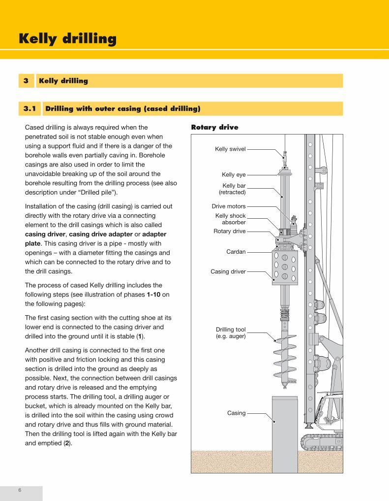
Cased.drilling.is.always.required.when.the.penetrated.soil.is.not.stable.enough.even.when.using.a.support.fluid.and.if.there.is.a.danger.of.the.borehole.walls.even.partially.caving.in..Borehole.casings.are.also.used.in.order.to.limit.the.unavoidable.breaking.up.of.the.soil.around.the.borehole.resulting.from.the.drilling.process.(see.also.description.under.“Drilled.pile”)..
Installation.of.the.casing.(drill.casing).is.carried.out.directly.with.the.rotary.drive.via.a.connecting.element.to.the.drill.casings.which.is.also.called.casing driver,.casing drive adapter.or.adapter plate..This.casing.driver.is.a.pipe.-.mostly.with.openings.–.with.a.diameter.fitting.the.casings.and.which.can.be.connected.to.the.rotary.drive.and.to.the.drill.casings..
The.process.of.cased.Kelly.drilling.includes.the.following.steps.(see.illustration.of.phases.1-10.on.the.following.pages):
The.first.casing.section.with.the.cutting.shoe.at.its.lower.end.is.connected.to.the.casing.driver.and.drilled.into.the.ground.until.it.is.stable.(1)..
Another.drill.casing.is.connected.to.the.first.one.with.positive.and.friction.locking.and.this.casing.section.is.drilled.into.the.ground.as.deeply.as.possible..Next,.the.connection.between.drill.casings.and.rotary.drive.is.released.and.the.emptying.process.starts..The.drilling.tool,.a.drilling.auger.or.bucket,.which.is.already.mounted.on.the.Kelly.bar,.is.drilled.into.the.soil.within.the.casing.using.crowd.and.rotary.drive.and.thus.fills.with.ground.material..Then.the.drilling.tool.is.lifted.again.with.the.Kelly.bar.and.emptied.(2).
Rotary drive
Drive.motors
Kelly.eye
Kelly.swivel
Kelly.shock.absorber
Cardan
Casing.driver
Casing
Drilling.tool.(e.g..auger)
Kelly.bar.(retracted)
Rotary.drive

Kelly drilling
�
This.process.is.repeated.as.often.as.necessary.before.the.next.casing.section.is.positioned.and.installed..In.doing.so.it.is.important.to.observe.that.the.casing.is.always.deeper.than.the.drilling.tool.in.order.to.avoid.breaking.up.of.the.soil.below.the.casings.(3).
After.reaching.the.drilling.depth.corresponding.to.the.first.Kelly.section,.another.casing.section.is.positioned.and.drilled.into.the.ground.as.deeply.as.possible.(4)..
Subsequently,.the.connection.between.casings.and.rotary.drive.is.released.again.and.the.second.Kelly.section.is.extended.as.the.rotary.table.simultaneously.travels.upwards.(5).
When.the.drilling.tool.is.in.the.casing,.retracting.and.extending.of.the.Kelly.bar.is.effected.with.the.rope.of.the.Kelly.winch..The.whole.telescoping.process.is.controlled.through.this.winch.and.by.alternate.turning.of.the.inner.Kelly.bar.to.the.right.and.left..The.described.processes.(positioning.of.casing.sections,.installing,.emptying,.telescoping).are.repeated.until.the.projected.drilling.depth.is.reached.(6.to.10)..
Finally,.the.bottom.of.the.borehole.has.to.be.cleaned.using.a.drilling.bucket.(see.description.in.chapter.A,.Drilled.pile)..
Thereafter,.the.designated.fill.material.or.structural.element.is.inserted.into.the.cased.borehole.
For.instance,.when.producing.a.pile.the.reinforcement.and.concrete.are.introduced.into.the.casing..
The.extraction.of.the.casing.is.carried.out.step.by.step.–.one.section.after.the.other.-.using.the.casing.driver,.mostly.by.simultaneous.oscillating.and.pulling.

Kelly drilling
�
Kelly drilling illustrated by cased drilling
Positioning.and.inserting.of.the.first.drill.casing
Fitting.the.second.drill.casing,.emptying.it.by.drilling.and.removing.the.excavated.spoil.to.the.side.(several.times)
Drilling.down.until.end.of.section.1
Inserting.another.casing Extending.section.2
1 2 3 4 5

Kelly drilling
�
Emptying.by.drilling,.retracting.the.Kelly.bar.and.removing.the.excavated.spoil.to.the.side.(several.times)
Fitting.and.inserting.further.casings
Extending.section.3 Drilling.down.to.final.depth.(by.repeatedly.installing.the.casings.and.emptying.them)
Drilling.down.until.end.of.section.2
6 7 8 9 10

Kelly drilling
�0
3.2 Drilling with outer casing and casing oscillator
In.special.situations.the.installation.of.the.casings.may.require.the.additional.use.of.a.casing oscillator..This.is.the.case.if.the.torque.of.the.rotary.drive.and.the.crowd.force.are.not.sufficient.to.overcome.the.skin.friction.between.casing.and.soil,.or.if.the.casing.cannot.be.extracted.using.only.the.rig’s.pull.force..This.can.be.due.to.the.soil.conditions,.the.drilling.depth.or.the.large.drilling.diameter...The.casing.oscillator.is.able.to.hold.the.casings.and.to.install.and.extract.them.again.by.turning.
An.important.precondition.is.that.the.casing.oscillator.has.to.be.firmly.mounted.on.the.carrier.machine..
The.casing.oscillator.is.usually.positioned.on.the.working.level.exactly.at.right.angles.to.the.drilling.axis..For.raked.boreholes.it.is.therefore.required.to.create.a.raked.plane..The.casing.oscillator.encloses.and.clamps.the.casing.projecting.above.the.ground..A.clamping.collar.and.hydraulic.locking.cylinders.are.clamped.round.the.whole.circumference.of.the.casing..This.clamping.collar.can.be.turned.alternately.to.the.left.and.right.by.two.hydraulic.cylinders.(oscillation.cylinders).acting.at.an.angle,.while.two.vertical.hydraulic.cylinders.(hoist.cylinders).can.press.the.whole.clamping.and.turning.equipment.up.or.down..In.this.way.the.casings.are.installed.by.simultaneous.turning.to.the.left.and.right.(oscillating).and.pressing.down..
Kelly drilling system with casing oscillator
Casing.driver
Casing
Casing.oscillator
Carrier.machine
Kelly.winch
Crowd.winch
Auxiliary.winch
Leader.inclination.device
Leader
Leader.top.for.Kelly.rope
Kelly.bar.(retracted)
Kelly.rope

Kelly drilling
��
The.casing.oscillator.is.driven.directly.from.the.hydraulic.system.of.the.carrier.machine..Thus,.it.is.possible.to.simultaneously.operate.the.rotary.drive.and.the.casing.oscillator,.allowing.for.synchronous.drilling.and.casing.installation..When.combined.with.the.Kelly.drilling.method.the.rotary.drive.of.the.rig.is.mainly.used.for.rotating.the.drilling.tool.with.the.Kelly.bar.
The.drilling.process.for.emptying.the.casings.is.carried.out.in.the.same.way.as.for.cased.drilling.without.casing.oscillator.
Casing oscillator at work

Kelly drilling
��
3.3 Drilling without outer casing (uncased drilling)
With.suitable.soil.conditions.the.Kelly.drilling.method.can.also.be.applied.for.the.production.of.uncased.boreholes..The.most.frequently.used.drilling.tools.are.a.short.auger.and/or.a.drilling.bucket..The.application.of.a.core.barrel.and.a.roller.bit.(e.g..in.rock).is.also.possible..
a) Drilling without support fluid
For.drilling.without.support.fluid,.the.soil.must.be.free.of.water,.the.borehole.must.be.stable.throughout.its.entire.length.and.it.must.be.certain.that.there.is.no.danger.of.the.borehole.wall.even.partially.caving.in..Raked.boreholes.should.on.no.account.be.produced.without.a.continuous.casing..
The.upper.part.of.the.borehole.must.be.secured.with.a.protective.pipe.of.at.least.2.m.length..Its.purpose.is.to.guide.the.drilling.tool.during.insertion.and.extraction.as.well.as.to.secure.the.borehole.against.possible.caving.in.caused.by.any.outside.influences.of.the.drilling.work.
The.drilling.process.is.carried.out.in.the.same.way.as.with.cased.drilling.
Protective.pipe

Kelly drilling
��
b) Drilling with support fluid
Another.variant.of.Kelly.drilling.without.borehole.casing.is.drilling.with.a.borehole.supported.by.fluid..The.upper.part.of.the.borehole.must.be.secured.with.a.protective.pipe.of.at.least.2.m.length.
This.method.secures.the.borehole.wall.in.unstable.soil.layers.against.caving.in.through.excess.fluid.pressure..The.support.fluid.generally.used.is.a.clay.or.bentonite.suspension.or.a.polymer.suspension..It.is.important.to.observe.that.during.the.whole.drilling.process.and.also.during.installation,.of.e.g..concrete.(when.producing.a.pile),.the.level.of.support.fluid.in.the.borehole.never.sinks.below.the.lower.edge.of.the.protective.pipe..
The.support.fluid.emerging.up.again.when.pumping.in.concrete.or.inserting.another.installation.material.has.to.be.pumped.off..It.is.either.harmlessly.disposed.of.or,.most.often,.delivered.to.a.regeneration.plant.where.it.is.recycled.to.be.reused.
Regarding.its.composition,.the.clay.or.bentonite.suspension.equates.to.the.support.fluid.used.during.the.production.of.cast-in-place.slurry.walls..Detailed.data.hereto.can.be.found,.among.others,.in.the.German.standard.DIN.4126.(EN.1538)..See.also.the.description.in.the.chapters.“Slurry.wall.installation“.and.Slurry.wall.(K).
Support.fluid
Protective.pipe

Kelly drilling
��
4 Advantages of the Kelly drilling method
-..The.telescopic.Kelly.bar.allows.for.great.drilling.depths.with.limited.leader.height.without.extension.of.the.drilling.rod..
-..The.borehole.wall.can.be.supported.with.drill.casings.or.with.support.fluid.
-..With.borehole.casing,.the.process.can.be.carried.out.in.virtually.any.soil.
-..Very.flexible.adaptation.to.various.soil.conditions.through.the.use.of.various.drilling.tools.
-..Quick.and.simple.change.of.the.drilling.tool.thanks.to.standardised.connections.
-..Possible.application.in.all.soil.types,.including.rock.
-..When.using.special.drilling.tools.obstacles.of.any.kind,.even.wood,.reinforced.concrete.and.steel.can.be.penetrated.

Kelly drilling
��
5 Application limits
The.limits.arise.on.the.one.hand.from.the.maximum.possible.drilling.depths.that.can.be.achieved.with.the.drilling.diameters.used.and.the.drilling.tools.applied.based.on.the.soil.conditions,.and.on.the.
other.hand.from.the.size.(length,.width,.height).of.the.equipment.used.and.the.pull.force.of.the.carrier.machine.as.well.as.the.achievable.torque.
Drilling rig Drilling depth Maximum drilling diameterup to uncased cased
LB.16.with.rotary.drive.BA.160from.Kelly.MD.15/2/16to.Kelly.MD.15/3/27
14.m25.m
900.mm 750.mm
LB.20.with.rotary.drive.BA.200from.Kelly.MD.28/3/24to.Kelly.MD.28/3/33
22.m31.m
1,900.mm 1,500.mm
LB.24.with.rotary.drive.BA.240from.Kelly.MD.28/3/24to.Kelly.MD.28/4/42
22.m40.m
1,900.mm 1,500.mm
LB.28.with.rotary.drive.BA.280from.Kelly.MD.28/3/24to.Kelly.MD.28/4/54
22.m52.m
1,900.mm 1,500.mm
LB.36.with.rotary.drive.BA.360from.Kelly.MD.36/3/30to.Kelly.MD.36/4/60
28.m58.m
2,300.mm 2,000.mm

Kelly drilling
��
6 Machine diagrams showing equipment
LB 16 LB 20/LB 24 LB 28/LB 36
1784
0
1492
1480
0
2123
1/22
845
1788
0/19
410
2560
0/26
200
2203
0/22
290
6.1 Carrier machines with Kelly drilling equipment (rope crowd)
1562
/156
0
1637
/182
4
Carrier.machine
Leader
Leader.top.for.Kelly.rope
Auxiliary.winch
Rotary.drive
Kelly.winch
Crowd.winch
5000 5442/5629 5895/6380

Kelly drilling
��
If.required.an.additional.hydraulic.casing.oscillator.is.used.which.has.to.be.firmly.mounted.on.the.carrier.machine..
Designation Distance drilling axis to Suitable for casings with Height Widthcarrier connection
Afront edge
Eexternal diameter up to
D H B
VRM.118.KL 2,270.mm 1,000.mm 880.mm 1,485.mm 2,050.mm
VRM.120.KL 2,270.mm 1,000.mm 1,200.mm 1,485.mm 2,050.mm
VRM.150.KL 2,800.mm 1,420.mm 1,500.mm 1,600.mm 2,500.mm
VRM.200.KL 3,545.mm 2,015.mm 2,000.mm 1,685.mm 3,220.mm
VRM.250.KL 3,715.mm 2,265.mm 2,500.mm 1,855.mm 4,000.mm
Overview of selected hydraulic casing oscillators (flat design)
The.hydraulic.supply.is.generally.provided.by.the.carrier.machine.
D
H
A
B
E
Carrier.machine

Kelly drilling
��
6.2 Tool system
Casing.driver
Rotary.drive
Max..drilling.depth
Drilling.tool
Kelly bar transport position
Kelly bar extended (3 sections/ 4 sections)
DA
The.Kelly bar.transfers.the.torque.and.the.crowd.force.to.the.drilling.tool..The.type.designation.refers.to.the.max..admissible.torque,.the.number.of.integrated.telescopic.drilling.rods.and.the.maximum.nominal.drilling.depth.(e.g..MD.28/3/30.corresponds.to.admissible.torque.of.280.kNm,.3-fold.Kelly,.max..drilling.depth.30.m)..The.actually.achievable.drilling.depth.depends.on.the.applied.drilling.tool.and.the.type.of.borehole.casing..In.case.of.cased.boreholes.without.casing.oscillator.it.is.approx..0.5.m.–.0.9.m.less..The.Kelly.bars.are.designed.for.various.(absorbable).torques..
Each.Kelly.bar.has.a.Kelly.eye.and.a.Kelly.swivel.with.swivel.protection.at.its.upper.end..The.lower.end.is.equipped.with.a.shock-absorber,.consisting.of.a.coil.spring.(up.to.7.t).or.disc.springs.(over.7.t).depending.on.the.weight.of.the.Kelly.bar.

Kelly drilling
��
Kelly bars (examples)
Type Number.of.
drilling.rods
Max..admissible.
torque.(kNm)
Diameter.of.outer.bar.
(mm).D.=
Max..drilling.depth..
(m).
Length.(retracted).
(mm).A.=
MD.28/3/24
MD.28/3/27
MD.28/3/30
MD.28/3/33
MD.28/3/36
3 280 419
22
25
28
31
34
9,880
10,880
11,880
12,880
13,880
MD.28/4/36
MD.28/4/42
MD.28/4/48
MD.28/4/54
4 280 419
34
40
46
52
11,130
12,630
14,130
15,630
MD.36/3/30
MD.36/3/363 360 470
28
34
12,000
14,000
MD.36/4/42
MD.36/4/48
MD.36/4/54
MD.36/4/60
4 360 470
40
46
52
58
13,000
14,500
16,000
17,500
Note:.The.listed.Kelly.bars.are.adapted.for.use.with.the.described.LB.drilling.rigs.

Kelly drilling
�0
Possible.drilling tools.are.short.augers,.drilling buckets.and.core barrels..The.outer.diameter.of.these.drilling.tools.matches.the.inner.diameter.of.the.drill.casings.applied..The.augers.feature.an.effective.length.of.1.5.m..The.upper.end.holds.the.Kelly.box..For.drilling.in.various.soil.types,.single-start.augers,.double-start.augers.and.so-called.tapered.augers.with.special.bits.are.available..Augers.are.usually.fitted.with.a.pilot.
Drilling buckets.are.designed.for.drilling.in.sandy,.loose.soil.types.as.well.as.for.drilling.in.all.types.of.loose.soils.in.groundwater.or.for.cleaning.the.bottom.of.the.borehole..They.are.equipped.with.a.hinged.swivel.bottom.plate..They.can.be.of.the.single-start.or.double-start.type.with.or.without.a.pilot..For.rock.of.high.workability.there.are.special.rock.drilling.buckets..The.effective.length.is.1.2.m.
For.drilling.in.rock.up.to.medium.strength.and.in.non-reinforced.concrete.core barrels.are.used...They.can.be.fitted.with.cutting bits,.with.round shank bits.or.with.roller bits..The.drilling.cuttings.produced.with.core.barrels.always.have.to.be.extracted.alternately.with.a.drilling.bucket..The.effective.length.is.1.5.m.
Auger
Kelly.box
Tapered auger
Hollow.stem
Screw.flight
Flight.pitch
Cutting.tool
Cutting.diameter
Pilot
Effective.length
Drilling bucket
Core barrel
Trip.mechanism
Pilot
Cutting.tool
Kelly.box
Swivel.bottom.plate
Cutting.diameter
Effective.length
Cutting.tool
Kelly.box
Cutting.diameter
Effective.length

Kelly drilling
��
As.borehole.casings.mainly.double.wall.casings.are.used..For.drilling.diameters.of.minimum.150.cm.single.wall.casings.are.also.applied..The.individual.casing.sections.are.connected.to.each.other.via.welded-on.casing joints.(male.and.female.part)..The.casing.joints.are.coupled.with.conical.bolts..Drill.casings.are.produced.in.effective.lengths.between.1.m.and.6.m..The.total.number.of.casing.sections.assembled.for.a.cased.borehole.is.also.called.casing string..
For.cased.boreholes.produced.using.the.Kelly.drilling.method.casings.with.an.outer.diameter.between.600.mm.and.1,800.mm.are.used.
The.first.(bottom).section.of.a.casing.string.is.fitted.with.a.cutting shoe.(also.called.pipe shoe.or.casing shoe)..It.can.also.be.equipped.with.a.welded-on.cutting ring..Depending.on.the.type.of.application.and.on.the.soil.type,.the.cutting.shoes.and.cutting.rings.are.equipped.with.armoured.cutting blocks,.carbide.tipped.weld-on teeth,.carbide.tipped.teeth.or.bits.
The.casing.driver.is.mounted.between.the.rotary.drive.and.the.casing..It.is.coupled.with.the.rotary.drive.in.such.a.way.as.to.ensure.co-rotation.and.that.tensile.and.compression.strengths.are.transmitted..The.casing.driver.is.a.pipe.mostly.designed.with.openings.with.a.diameter.fitting.the.casings..At.the.lower.end.a.casing.joint.is.welded.on..Casing.drivers.must.be.able.to.absorb.the.maximum.torque.of.the.rotary.drive..They.are.designed.for.torques.of.up.to.150.kNm.and.up.to.400.kNm..Their.standard.length.is.1.9.m.or.2.2.m.
Casing
Cutting shoe Cutting ring
Casing driver
Casing.joint.–..female.part
ODCasing.diameter
Casing.joint.–..female.part
Casing.joint.–..male.part
Casing.diameter
ID
OD
Effective.length
Casing.diameter
ID
ODCasing.diameter
ID
OD
Effective.length
Effective.length

Deep compaction
M / �
1 General
In.deep.foundation.and.construction.engineering.various.methods.are.used..Their.purpose.is.to.modify.the.natural.properties.of.the.soil.in.such.a.way.that.it.meets.with.the.demands.of.the.construction.purposes.projected.for.the.area..This.includes.methods.which.only.serve.to.improve.soil.with.insufficient.load-bearing.capacity,.so.it.can.be.used.to.accommodate.construction.loads..In.foundation.engineering.these.methods.are.summarised.in.the.term.building ground improvement.(also.called.soil improvement)..
Building.ground.improvement.means.making.positive.changes.to.the.natural.properties.of.a.soil.with.a.view.to.construction,.through.treatment.and/or.the.addition.of.other.materials..The.aim.of.the.building.ground.improvement.process.is.to.increase.the.natural.load-bearing.capacity.of.the.soil.in.order.to.accommodate.loads.from.building.works.or.embankments.and/or.to.reduce.the.compressibility.(settlement).of.the.soil..The.methods.used.can.be.divided.into.the.following.systems:.
-..Ground.improvement.through.input.of.energy-..Ground.improvement.through.the.addition.of.
materials-..Ground.improvement.through.the.removal.of.
water
The.replacement.of.soil.(soil.exchange).with.a.ground.material.of.another.“better”.type.is.not.ground.improvement.in.this.sense..
The.many.different.methods.of.building.ground.improvement.can.be.divided.into.three.groups:
1...Methods.where.specific.energy.is.input,.e.g..during.execution.of.vibratory.compaction.on.the.surface..This.near-surface.ground.improvement.through.energy.input.can.be.achieved.using.tamping.or.vibrating.machines..Such.methods.are.diversely.applied.in.road.construction.and.earth-moving.work,.but.are.not.described.here..In.foundation.engineering,.however,.methods.reaching.deeper.down.into.the.subsoil.are.applied.in.order.to.improve.the.building.ground..One.of.these.methods.is.deep compaction,.which.is.used.above.all.for.compacting.mainly.non-cohesive.soils.(also.gravel.and.sand.and.mixtures.of.them,.with.only.little.silt.content).through.energy.input..This.method.is.also.known.as.vibro-flotation..It.is.exclusively.carried.out.using.deep.vibrators.hanging.freely.on.the.rope.of.a.crane.or.an.excavator..LIEBHERR.duty.cycle.crawler.cranes.with.lattice.boom.are.especially.suitable.for.this.application..

Deep compaction
M / �
M
2...Methods.in.which.soil.is.displaced.and.material.is.added.in.addition.to.the.input.of.energy..This.is.the.case,.for.example,.when.carrying.out.vibro-replacement.or.when.producing.vibration columns..These.methods.are.further.developed.variants.of.the.deep.compaction.method,.where.a.so-called.bottom-feed vibrator.(horizontal.vibrator).is.used.to.produce.load.dissipating.columns.of.gravel.and.sand.in.soil.which.is.only.slightly.or.not.compactable..Instead.of.gravel.and.sand,.a.gravel-sand.mixture.blended.with.cement.in.a.dry.mixing.process.can.be.installed..Vibration.columns.produced.in.this.way.are.called.grouted vibro-replacement columns...Thereby,.the.vibrator.is.always.guided.on.a.leader..For.this.purpose,.a.LIEBHERR.LRH.piling.rig.–.a.HS.duty.cycle.crawler.crane.with.lattice.boom.and.a.leader.fixed.to.the.boom.top.(called.fixed leader).–.can.be.used..
3...Methods,.achieving.better.water.drainage.or.an.increase.in.load-bearing.capacity.or.better.workability.for.subsequent.construction.techniques.through.the.extraction.of.soil.by.drilling.and.the.installation.of.a.soil.replacement.material..This.includes.the.sand.and.gravel.piles.described.in.chapter.D.as.well.as.soil.exchange.drilling..
A.further.method.of.producing.vibration.columns.by.installing.a.specially.designed.vibration.pipe.is.described.in.the.compendium volume I, Piling and drilling rigs, LRB series..
Assessments.and.proposals.as.to.which.method.of.ground.improvement.is.appropriate.to.achieve.the.desired.result.are.normally.made.by.consultants.and.geotechnical.engineers.from.institutes.and.engineering.consultants.specializing.in.this.area..
Another.deep.compaction.method.is.impact compaction,.also.known.as.dynamic deep compaction.or.dynamic intensive compaction.(see.description.in.chapter.P).

Deep compaction
M / �
Soil.compaction.using.deep.vibrators,.i.e..vibro-flotation.or.vibro-compaction,.is.one.of.the.oldest.deep.compaction.methods..It.was.developed.and.made.ready.for.implementation.in.Germany.in.the.1930’s..Today.it.is.applied.more.and.more.often.throughout.the.world.
With.a.deep.vibrator.the.soil.is.compacted.through.a.cylindrical.vibrator.in.which.the.eccentric.weight.rotates.around.a.vertical.drive.shaft.(horizontal.vibrator,.see.description.under.“Vibrating”)..
The.vibrator.is.situated.at.the.lower.end.of.a.heavy.pipe.which.is.suspended.on.the.rope.of.a.crane.or.a.HS.duty.cycle.crawler.crane..Vibrator.and.pipe.together.with.the.extension.pipes.feature.a.length.at.least.as.long.as.the.projected.penetration.depth.of.the.vibrator..
In.foundation.engineering.it.is.known.that.non-cohesive.(granular).soil.is.compressed.if.exposed.to.construction.loads.and.thus,.settlement.occurs..During.this.process,.the.soil.grains.are.rearranged.from.their.original.position.(loosely.layered.with.large.pore.volume).to.a.more.compact.position.(more.densely.layered.with.smaller.pore.volume),.i.e..the.soil.is.compacted..The.application.of.vibro-flotation.is.based.on.the.fact.that.this.rearrangement.of.the.soil.grains.also.occurs.due.to.the.influence.of.vibrations,.i.e..the.soil.is.
compacted..If.this.compaction.is.effected.before.the.construction.loads.are.applied,.the.possibility.of.subsequent.settlements.of.the.soil.are.prevented.to.a.large.extent..Thus,.a.deep.vibrator.is.used.to.improve.the.soil.for.construction.purposes.
2 Production (see also “Vibrating”), applications
2.1 Vibro-flotation

Deep compaction
M / �
M
The.vibrator.(out.of.operation).is.hoisted.on.the.rope,.brought.into.the.projected.position.and.placed.on.the.ground.(1).
As.vibration.is.switched.on,.the.rope.is.slowly.lowered..In.order.to.support.penetration,.water.emerging.from.the.vibrator.tip.is.added.under.pressure..In.this.way.the.deep.vibrator.penetrates.the.ground.due.to.its.own.weight.and.the.jetting.force.of.the.pressurised.water..In.most.cases.the.vibrator.is.sunk.into.the.building.ground.in.one.working.step.(2).
After.the.projected.depth.is.reached,.water.jetting.is.reduced.or.completely.switched.off.and.the.vibrator,.which.remains.in.operation,.is.pulled.up.step.by.step.(3)..
Thus,.a.compacted.soil.structure.of.cylindrical.shape.is.created.around.the.vibrator..Extraction.of.the.vibrator.is.executed.in.predetermined.hoisting.steps.and.intervals..The.reduction.of.the.pore.volume.in.the.soil.due.to.vibration.leads.to.a.funnel-shaped.settlement.around.the.vibrator..This.is.compensated.by.adding.gravel.or.sand.or.adjacent.soil.material.(4).(5).
The process of vibro-flotation includes the following steps:
1 2 3 4 5

Deep compaction
M / �
The.combination.and.appropriate.arrangement.of.the.vibration.points.allows.to.compact.soil.structures.of.any.size.and.depth.in.various.geometrical.shapes..Thus,.the.building.ground.can.be.exactly.compacted.as.required.for.punctiform.loads,.line.or.stripe.loads.as.well.as.for.areal.loads.
Vibro-flotation.is.mainly.applied.for.improving.loose.sands.and.gravels.as.well.as.artificial.fills..This.method.is.predominantly.used.for.improving.building.ground.which.is.intended.to.be.exposed.to.large-area.loads.(e.g..fuel.depots,.road.embankments,.stock.grounds,.airport.runways,.industrial.sites)..Another.possible.application.is.the.compaction.(reduction.in.volume).of.slag.heaps.and.mine.dumps.
The.diameter.of.the.compacted.soil.column.depends.largely.on.the.original.soil.structure.and.the.vibration.energy.applied..It.can.be.as.much.as.4.m..
The.distance.between.the.compaction.points.for.producing.a.continuous.area-wide.compaction.is.between.2.5.m.and.4.0.m..
HS.carrier.machines.from.LIEBHERR.are.particularly.well.suited.and.cost-effective.in.the.case.of.vibro-flotation.applications.where.it.is.required.to.go.to.great.depths..Installation.depths.of.up.to.30.m.can.easily.be.achieved.using.the.HS.885.carrier.machine.
Compaction under foundations
Compaction under areal loads
Consolidation.area.for.each.column
Compacted..ground.columns
e.g..Tank
A
Cross-section.A-A
A
A
Cross-section.A-A
A
Consolidation.area.for.each.column
Deep compaction
M / �
M
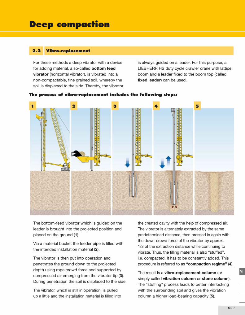
For.these.methods.a.deep.vibrator.with.a.device.for.adding.material,.a.so-called.bottom feed vibrator.(horizontal.vibrator),.is.vibrated.into.a.non-compactable,.fine.grained.soil,.whereby.the.soil.is.displaced.to.the.side..Thereby,.the.vibrator.
is.always.guided.on.a.leader..For.this.purpose,.a.LIEBHERR.HS.duty.cycle.crawler.crane.with.lattice.boom.and.a.leader.fixed.to.the.boom.top.(called.fixed leader).can.be.used.
2.2 Vibro-replacement
The.bottom-feed.vibrator.which.is.guided.on.the.leader.is.brought.into.the.projected.position.and.placed.on.the.ground.(1)..
Via.a.material.bucket.the.feeder.pipe.is.filled.with.the.intended.installation.material.(2).
The.vibrator.is.then.put.into.operation.and.penetrates.the.ground.down.to.the.projected.depth.using.rope.crowd.force.and.supported.by.compressed.air.emerging.from.the.vibrator.tip.(3)..During.penetration.the.soil.is.displaced.to.the.side.
The.vibrator,.which.is.still.in.operation,.is.pulled.up.a.little.and.the.installation.material.is.filled.into.
the.created.cavity.with.the.help.of.compressed.air..The.vibrator.is.alternately.extracted.by.the.same.predetermined.distance,.then.pressed.in.again.with.the.down-crowd.force.of.the.vibrator.by.approx..1/3.of.the.extraction.distance.while.continuing.to.vibrate..Thus,.the.filling.material.is.also.“stuffed”,.i.e..compacted..It.has.to.be.constantly.added..This.procedure.is.referred.to.as.“compaction regime”.(4)..
The.result.is.a.vibro-replacement column.(or.simply.called.vibration column.or.stone column)..The.“stuffing”.process.leads.to.better.interlocking.with.the.surrounding.soil.and.gives.the.vibration.column.a.higher.load-bearing.capacity.(5).
The process of vibro-replacement includes the following steps:
1 2 3 4 5

Deep compaction
M / �
3 Characteristics, special features
In.comparison.to.other.special.deep.foundation.methods.such.as.drilled.piles.or.impacted.piles,.the.methods.of.vibro-flotation.and.vibro-replacement.offer.many.technical.advantages.in.terms.of.the.process..The.high.degree.of.geometric.flexibility.allows.the.process.to.be.optimally.adapted.to.the.given.conditions..The.ability.to.produce.variable.structural.forms.allows.the.process.to.be.matched.to.the.particular.construction.task.
As.the.achievable.improvement.of.the.soil’s.load-bearing.capacity.is.very.high,.settlements.caused.by.subsequent.loading.or.by.dynamic.stress.can.be.disregarded,.as.they.have.already.been.effectuated.by.the.vibration.
Compared.to.other.deep.foundation.methods.these.methods.excel.in.their.short.execution.time.and.are.therefore.very.cost-efficient..This.is.above.all.due.to.the.vibrator.being.installed.in.one.single.step..
Subsequent.building.work.can.be.carried.out.after.a.short.period.of.time.and.within.close.vicinity.of.the.ongoing.improvement.of.the.subsoil..The.building.ground,.which.has.been.compacted.area-wide,.is.immediately.ready.for.subsequent.building.work.as.in.the.case.of.a.common.shallow.foundation.
The.compaction.is.equally.effective.above.and.below.the.groundwater.table..The.success.of.the.compaction.is.neither.affected.by.flowing.groundwater.nor.by.tides..Soil.improvement.using.vibro-flotation.and.vibro-replacement.is.permanent.and.can.not.be.disturbed.even.through.aggressive.groundwater.
As.no.soil.is.extracted.with.this.method,.the.compaction.of.contaminated.soils.does.not.produce.any.additional.costs.for.soil.disposal..
To.cope.with.changing.soil.conditions,.the.installation.pattern.can.be.changed.immediately.without.interrupting.the.serial.installation.process..
Not.only.the.pattern.of.the.compaction.points.but.also.the.compaction.depths.can.be.easily.adapted.to.the.loads.from.the.building.and/or.the.building.work.without.changing.equipment.

Deep compaction
M / �
M
4 Application limits
Where.obstacles.are.encountered.in.the.soil,.the.installation.process.normally.has.to.be.aborted.and.the.vibrator.inserted.again.in.a.different.location..
The.application.is.limited.to.the.compaction.of.non-cohesive.soils.with.a.low.silt.content.(less.than.5%).
Special.measurements.need.to.be.taken.if.the.compaction.is.to.be.carried.out.next.to.buildings.with.shallow.or.deep.foundation.
Application.limits.are.also.given.in.terms.of.vibration.emissions.generated.in.the.process..
Due.to.the.stress.during.extraction.the.weight.of.the.vibrator.should.not.exceed.40%.of.the.admissible.hook.load..The.applied.pull.force.has.to.be.less.than.admissible.for.the.vibrator.
Limiting grading curves
Vibro-flotation
100
80
60
40
20
90
70
50
30
10
Clay Silt Sand Gravel
Sto
nes
Fine Medium Coarse Fine Medium Coarse Fine Medium Coarse
Grain.size.[mm]
Scr
een.
und
erflo
w.
[%.b
y.w
eigh
t]
0.0006 0.002 0.006 0.02 0.06 0.2 0.6 2.0 6.0 20 60 100
Deep compaction
M / �0
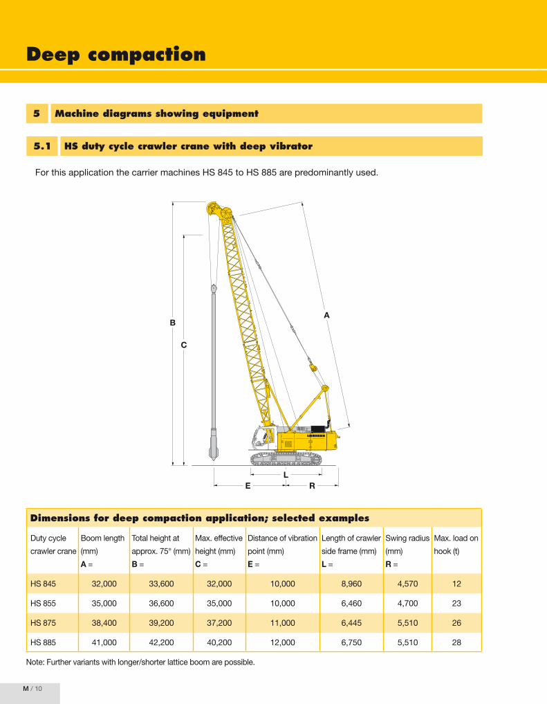
For.this.application.the.carrier.machines.HS.845.to.HS.885.are.predominantly.used.
5 Machine diagrams showing equipment
5.1 HS duty cycle crawler crane with deep vibrator
Note:.Further.variants.with.longer/shorter.lattice.boom.are.possible.
Dimensions for deep compaction application; selected examples
Duty.cycle.
crawler.crane
Boom.length.
(mm)
A.=.
Total.height.at.
approx..75°.(mm)
B.=.
Max..effective.
height.(mm)
C.=
Distance.of.vibration.
point.(mm).
E.=.
Length.of.crawler.
side.frame.(mm)
L.=
Swing.radius.
(mm)
R.=
Max..load.on.
hook.(t).
HS.845 32,000 33,600 32,000 10,000 8,960 4,570 12
HS.855 35,000 36,600 35,000 10,000 6,460 4,700 23
HS.875 38,400 39,200 37,200 11,000 6,445 5,510 26
HS.885 41,000 42,200 40,200 12,000 6,750 5,510 28
LR
B
E
C
A

Deep compaction
M / ��
M
5.2 LRH with bottom feed vibrator (vibro-replacement)
A
B
The following combinations of equipment can be applied
LRH.200 LRH.400 LRH.600
Carrier.machine HS.845
HS.855
HS.855
HS.875
HS.885
HS.895
Max..leader.length.. A.= 33.m 42.m 50.m
Max..capacity
Max..pull./.push.force
20.t
40.t
35.t
60.t
65.t
80.t
Max..effective.length*. B.= approx..28.m approx..37.m approx..44.m
*.Depending.on.the.applied.type.of.bottom.feed.vibrator

Deep compaction
M / ��
6 Quality assurance
The.optimum.pattern.of.the.compaction.points.is.chosen.from.experience.or.according.to.tests.previously.carried.out..
The.following.production.parameters.need.to.be.monitored.and.recorded.on.data.recording.systems.throughout.the.entire.production.process.of.vibro-flotation:
-..The.penetration.depth.of.the.vibrator.from.the.working.level.downward
-.The.duration.of.the.compaction.process
-.The.energy.input.(e.g..oil.pressure).of.the.vibrator
-.Pressure.and.quantity.of.the.jetting.water
-..The.distance.between.the.compaction.points.(grid.dimension)
-..The.amount.of.material.added.for.filling.the.vibrating.hopper
The.following.controls.are.recommended.after.completion.of.the.compaction.works:
-..Large-area.levelling.in.order.to.determine.the.effected.settlements
-..Determination.of.the.compacted.soil’s.density.via.static.and.dynamic.penetration.tests
-..Determination.of.the.new.strength.properties.of.the.soil.through.test.loadings.(load.tests.or.plate.load.tests)
Bo
ok
Re
com
me
nd
ati
on
Liebherr-Werk Nenzing GmbH (Hrsg.)
Special Deep Foundation Compendium Methods and Equipment. Volume II: Drilling machines and hydraulic crawler cranes The methods and equipment technology employed in the deep foundation industry have improved rapidly in recent years. The ingenuity of civil engineers, the results of new scientific research and the ongoing and new developments in machine technology have all led to the acceleration of this process. Applying technologies that have become very complex, and selecting the suitable machinery and equipment, demand ever more specialized knowledge and practical experience. It has become very difficult for users and manufacturers of special deep foundation machinery to maintain an overview of the level of technology in the sector. Both volumes provide a comprehensive overview of the special deep foundation applications, equipment and processes. They are intended as an aid to planning and implementation, and aim to help practitioners, public authorities, engineering companies and students
to broaden and complete their level of knowledge. They are targeted primarily at occupational engineers and applications in the field. The individual chapters discuss manufacturing techniques and potential applications, along with the associated machine components. The specifics of each method and machine technology are examined in detail. Since the first volume of the compendium on Special Deep Foundation was published in March 2008, it has become a standard reference book. We are about to finish Volume II which certainly meets the standard set by Volume I. 336 pages. Hardcover. Publication date: September 2009
From the contents: Drilled pile Augered piles · Partial and full displacement
augered piles Steel beam profiles and steel pipes in bore holes Sand- and gravel piles, Soil exchange Predrilling Well drilling GEWI piles High-pressure injection
Wet-mix pile/MIP pile Slurry wall Impact driving of steel profiles Deep compaction Impact driving of steel sheet pile profiles, steel
beam profiles and steel pipes Impact driving of precast reinforced concrete and
prestressed concrete driven piles Dynamic soil compaction
⌦ Fax-Answer to +49(0)30 47031 240 Quantity Order-No. Title Unit price
978-3-433-02932-9 Special Deep Foundation € 129,-
905221 Publishing Index Verlag Ernst & Sohn For free
2478 1 sample issue journal "Geomechanics and Tunnelling" For free
Delivery and Invoice address: private business Order-Code: 100 773 Company
Contact person Telephone
UST-ID Nr./VAT-ID No. Fax
Street//No. E-Mail
Land - Zip code location
Date/Signature *In EU countries the local VAT is effective for books and journals. Postage will be charged. Whilst every effort is made to ensure that the contents of this leaflet are accurate, all information is subject to change without notice. Our standard terms and delivery conditions apply. Prices are subject to change without notice. Date of Information: 18.09.09 (homepage_extract)
Wilhelm Ernst & Sohn Verlag für Architektur und technische Wissenschaften GmbH & Co. KG Rotherstraße 21 10245 Berlin Germany www.ernst-und-sohn.de


