Helsinki University of Technology
Department of Communications and Networking
Networking Laboratory
Jussi Ryynänen
Routed End-to-End Ethernet Network –
Proof of Concept
Master’s Thesis submitted in partial fulfilment of the requirements for the degree
of Master of Science in Technology.
May 14th
, 2008
Jussi Ryynänen
Supervisor: Professor Raimo Kantola
Instructor: D.Sc.(Tech.) Mika Ilvesmäki, Mamentor Oy
HELSINKI UNIVERSITY
OF TECHNOLOGY
ABSTRACT OF THE
MASTER’S THESIS
Author:
Name of the Thesis:
Jussi Matias Ryynänen
Routed End-to-End Ethernet – Proof of Concept
Date: May 14th, 2008 Number of Pages: xi + 85
Department: Department of
Communications and
Networking
Professorship: S-38
Supervisor:
Instructor:
Professor Raimo Kantola
D.Sc.(Tech.) Mika Ilvesmäki, Mamentor Oy
The main goal of this thesis is to investigate and analyse the Ethernet and IEEE 802.1
standards, and IPv4 and IPv6 protocols. From those combine a new idea of Routed
End-to-End Ethernet in theory and to build a Proof of Concept network that shows it
in a small scale. This concept would solve the address exhaustion problem by using
MAC and NSAP addresses for host identification and for routing Ethernet packets in
the network.
From Ethernet and IEEE 802.1 standards we found that the main problem of the
Ethernet is that it does not have hierarchical addresses. Hierarchical addresses would
allow efficient routing enabling the network to scale globally. IEEE 802.1 has many
standards with features for scaling Ethernet networks better, but they are still not
enough. The only routing protocols used in the Ethernet networks are still the
Spanning Tree Protocols.
Internet Protocol version 4 that is the dominant network protocol in the Internet, has a
hierarchical address space enabling efficient routing. A big problem with IPv4 is that
the address space is small and is running out of addresses. IPv6 has larger address
space, but for some reason the deployment is really slow.
RE2EE would use Ethernet added with hierarchical addresses for the Internet. This
would make the address space large enough and also efficient routing would be
possible. In the Proof of Concept a small scale network was built, which showed that
it is possible to create the basic functionalities of RE2EE using only Ethernet packets.
Keywords: IP, IPv4, IPv6, Ethernet, NSAP, RE2EE, Networking, Internet

TEKNILLINEN
KORKEAKOULU
DIPLOMITYÖN
TIIVISTELMÄ
Tekijä:
Työn nimi:
Jussi Matias Ryynänen
Päästä-päähän reitittävä Ethernet – Tekninen kokeilu
Päivämäärä: 14.05.2008 Sivuja: xi + 85
Osasto: Sähkö- ja
tietoliikennetekniikan osasto
Professuuri: S-38
Työn valvoja:
Työn ohjaaja:
Professori Raimo Kantola
TkT Mika Ilvesmäki, Mamentor Oy
Tämän diplomityön tavoitteena on tutkia ja analysoida Ethernet- ja IEEE 802.1 -
standardeja, sekä IPv4- ja IPv6-protokollia. Näiden parhaita puolia yhdistämällä
kehitettiin uusi päästä-päähän reitittävä Ethernet –konsepti, jonka mukaan
rakennettiin Proof of Concept –verkko. Tämä idea pyrkii ratkaisemaan Internetin
suurimman ongelman, jossa osoiteavaruudesta loppuvat osoitteet, käyttämällä
laitteiden identifioimiseen ja Ethernet-pakettien reitittämiseen sekä MAC- että
NSAP-osoitteita.
Hierarkkisuuden puute osoitteissa estää tehokkaan reitityksen ja sen takia Ethernet-
verkot eivät skaalaudu maailmanlaajuiseksi verkoksi. IEEE 802.1 -standardeissa on
parannettu Ethernet-verkkojen skaalautuvuutta, mutta osoitteistusta ei ole muutettu ja
reititykseen käytetään edelleen Spanning Tree -protokollaa.
Internet-protokollan versio 4:stä tuli Internetin hallitseva verkkoprotokolla, koska
siinä osoitteisto on hierarkkinen, mikä mahdollistaa tehokkaan reitityksen.
Ongelmaksi on kuitenkin muodostunut pieni osoiteavaruus, josta osoitteet alkavat
loppua. IPv6:ssa on suurempi osoiteavaruus, mutta siltikään se ei ole syrjäyttänyt
IPv4-osoitteita.
RE2EE:n ideana on lisätä Ethernet-verkkoon hierarkkiset osoitteet, jotka yhdessä
mahdollistaisivat riittävän ison osoiteavaruuden ja tehokkaan reitityksen. Proof of
Conceptissa luotiin RE2EE-verkko pienessä mittakaavassa ja todistettiin sen avulla
RE2EE:n perusominaisuuksin toteuttaminen käyttämällä ainoastaan Ethernet-
paketteja.
Avainsanat: IP, IPv4, IPv6, Ethernet, NSAP, RE2EE, verkottaminen, Internet

Acknowledgment
I
Acknowledgment
This Master’s thesis completes my studies for the Master of Science degree. The
work for this thesis was carried out at the Networking Laboratory of Helsinki
University of Technology between May 2007 and May 2008.
The idea of this Routed End-to-End Ethernet has been developed in the
Networking Laboratory. The main people behind it have been Lic.Sc.(Tech.)
Marko Luoma, professor Raimo Kantola and D.Sc.(Tech.) Mika Ilvesmäki.
I would like to thank my instructor Mika Ilvesmäki for helping me with the main
structure of the thesis and for the development comments for my thesis. Also I
would like to thank my supervisor Raimo Kantola who gave this topic for me to
research.
Espoo, May 12th, 2008
Jussi Ryynänen

Table of Contents
II
Table of Contents
ACKNOWLEDGMENT.......................................................................................................................I
TABLE OF CONTENTS ....................................................................................................................II
LIST OF FIGURES ............................................................................................................................VI
LIST OF TABLES ............................................................................................................................VII
LIST OF ACRONYMS .................................................................................................................. VIII
1 INTRODUCTION..........................................................................................................................1
2 ETHERNET AND IEEE 802.1 ....................................................................................................4
2.1 LAYERED APPROACH TO NETWORKING ..................................................................................4
2.2 HISTORY OF THE ETHERNET.....................................................................................................5
2.3 ETHERNET FRAME FORMAT .....................................................................................................6
2.3.1 EtherType .........................................................................................................................6
2.3.2 Ethernet Packet ................................................................................................................6
2.4 MAC ADDRESS ........................................................................................................................7
2.4.1 Extended Unique Identifier – EUI ..................................................................................8
2.5 MAC ADDRESS SCALABILITY ISSUES .....................................................................................8
2.6 ADDRESS TRANSLATION ..........................................................................................................9
2.7 IEEE 802.1 STANDARDS AND DRAFTS..................................................................................10
2.7.1 IEEE 802.1 – LAN/MAN Architecture..........................................................................10
2.7.2 IEEE 802.1Q – Virtual LANs ........................................................................................11
2.7.3 IEEE 802.1ad – Provider Bridges ................................................................................12
2.7.4 IEEE 802.1ah – Provider Backbone Bridges...............................................................12
2.7.5 IEEE 802.1Qay – Provider Backbone Bridge Traffic Engineering ...........................14
2.8 OTHER TECHNOLOGIES ..........................................................................................................14
2.8.1 Ethernet WAN ................................................................................................................14
2.8.2 Carrier Ethernet.............................................................................................................15

Table of Contents
III
2.9 SPANNING TREE PROTOCOL...................................................................................................15
2.9.1 IEEE 802.1w – Rapid Spanning Tree Protocol (RSTP) ..............................................16
2.9.2 IEEE 802.1s – Multiple Spanning Tree Protocol (MSTP) ..........................................17
3 ROUTING IN THE INTERNET...............................................................................................18
3.1 INTERNET PROTOCOL VERSION 4 NETWORKS ......................................................................18
3.1.1 Internet Protocol Version 4 Addresses.........................................................................18
3.1.2 Classless Inter-Domain Routing – CIDR .....................................................................19
3.1.3 Private Networking........................................................................................................20
3.1.4 Network Address Translation – NAT............................................................................20
3.1.5 Application Level Gateway ...........................................................................................23
3.1.6 Allocating an IPv4 Network Address............................................................................24
3.2 INTERNET PROTOCOL VERSION 6 NETWORKS ......................................................................25
3.2.1 Internet Protocol Version 6 Addresses.........................................................................25
3.2.2 Classless Inter-Domain Routing in IPv6......................................................................26
3.2.3 Private Networking and NAT in IPv6...........................................................................26
3.2.4 Allocating an IPv6 Network Address............................................................................26
3.3 PACKET DELIVERY METHODS IN NETWORKS .......................................................................27
3.4 ROUTING EXPLAINED .............................................................................................................27
3.4.1 Routing Algorithms........................................................................................................28
3.5 MOBILE IP...............................................................................................................................30
4 ROUTED END-TO-END ETHERNET – RE2EE..................................................................31
4.1 ABOUT THE CONCEPT.............................................................................................................31
4.2 NETWORK STRUCTURE...........................................................................................................32
4.2.1 Network Core .................................................................................................................33
4.2.2 Service Core ...................................................................................................................33
4.2.3 Mobility Layer................................................................................................................34
4.3 ADDRESSING AND USER IDENTITY IN RE2EE.......................................................................35
4.3.1 Network Service Access Point.......................................................................................36
4.4 ROUTING IN RE2EE................................................................................................................39
4.4.1 Routing Example............................................................................................................39
4.4.2 802.1aq and IS-IS ..........................................................................................................40
4.5 ADDRESS RESOLUTION MECHANISM.....................................................................................40
5 RE2EE – PROOF OF CONCEPT ............................................................................................42
5.1 DIFFERENCES BETWEEN RE2EE AND THE PROOF OF CONCEPT...........................................42
5.2 NETWORK EQUIPMENT...........................................................................................................43
5.3 NETWORK ELEMENTS EXPLAINED.........................................................................................44
5.3.1 Host.................................................................................................................................45

Table of Contents
IV
5.3.2 Provider Edge – PE.......................................................................................................46
5.3.3 Provider..........................................................................................................................46
5.3.4 Registry...........................................................................................................................46
5.3.5 Resolver ..........................................................................................................................46
5.3.6 Forwarder ......................................................................................................................47
5.4 ETHERNET PACKET GENERATION WITH SCAPY ....................................................................47
5.4.1 Implemented Ethernet Packets......................................................................................47
5.5 NETWORK FUNCTIONALITY AND THE STRUCTURE OF THE DATABASE................................48
5.5.1 REGISTRY Table ...........................................................................................................48
5.5.2 PROVIDERS Table ........................................................................................................49
5.5.3 Home PE Discovery by a Host......................................................................................50
5.5.4 Host Registering to PE ..................................................................................................50
5.5.5 PE Sending the Information to Other PE.....................................................................52
5.5.6 Host Sending Data to Other Host.................................................................................52
5.5.7 Inactivation of a Host ....................................................................................................56
5.6 USAGE OF THE PROOF OF CONCEPT NETWORK.....................................................................57
5.6.1 Home PE Node Discovery and Registration to It ........................................................57
5.6.2 Inactivation of the Host .................................................................................................57
5.6.3 Sending Packets .............................................................................................................57
5.6.4 Receiving Packets ..........................................................................................................58
6 ANALYSIS OF RESULTS.........................................................................................................59
6.1 ADDRESS SPACE .....................................................................................................................59
6.2 ROUTING .................................................................................................................................61
6.3 SCALABILITY OF THE RE2EE.................................................................................................61
6.4 SECURITY ................................................................................................................................63
6.5 RESULTS FROM THE PROOF OF CONCEPT ..............................................................................63
6.6 PROBLEMS ENCOUNTERED IN THE PROOF OF CONCEPT .......................................................65
6.6.1 Network Interface Cards ...............................................................................................65
6.6.2 Ethernet Packet Inside an Ethernet Packet..................................................................66
6.6.3 Replies Need to Be Delayed ..........................................................................................66
7 CONCLUSIONS ..........................................................................................................................67
7.1 FUTURE RESEARCH.................................................................................................................69
7.1.1 RE2EE and IP Networks ...............................................................................................69
7.1.2 Addressing......................................................................................................................69
7.1.3 Routing ...........................................................................................................................69
7.1.4 Service Discovery ..........................................................................................................69
7.1.5 Mobility Management....................................................................................................70
7.1.6 Other ...............................................................................................................................70

Table of Contents
V
REFERENCES....................................................................................................................................71
APPENDICES .....................................................................................................................................76
I GETDATA.PY................................................................................................................................76
II RE2EE_SERVER_X.PY ................................................................................................................77
III RE2EE_HOST_X.PY...................................................................................................................82
IV RE2EE_PROVIDER_XX.PY ........................................................................................................84

List of Figures
VI
List of Figures
FIGURE 2-1: OSI MODEL VS. TCP/IP MODEL.........................................................................................5
FIGURE 2-2: THE MOST COMMON ETHERNET FRAME FORMAT, TYPE II ...............................................6
FIGURE 2-3: ARP MESSAGE FLOW..........................................................................................................9
FIGURE 2-4: TAG CONTROL INFORMATION FIELD IN IEEE 802.1Q [IEE05]......................................11
FIGURE 2-5: DEVELOPMENT OF ETHERNET HEADERS [NOR07] ..........................................................13
FIGURE 3-1: IPV4 ADDRESS CLASSES AND HOW THEY ARE FORMED [TAN03] ...................................19
FIGURE 3-2: CLIENT-SERVER INTERACTION - ALLOCATING A NETWORK ADDRESS............................24
FIGURE 4-1: RE2EE NETWORK STRUCTURE [REDRAWN FROM KAN+07] ..........................................32
FIGURE 4-2: PACKET STRUCTURE OF RE2EE [REDRAWN FROM KAN+07] ........................................33
FIGURE 4-3: RE2EE PHYSICAL NETWORK AND SERVICE VLANS ......................................................34
FIGURE 4-4: PE ADDRESSING................................................................................................................35
FIGURE 4-5: GENERAL NSAP ADDRESS FORMAT [REDRAWN FROM COL+94] ..................................36
FIGURE 5-1: RE2EE NETWORK FOR THE PROOF OF CONCEPT ............................................................43
FIGURE 5-2: RE2EE NETWORK ELEMENTS ..........................................................................................45
FIGURE 5-3: SCREENSHOT OF MYSQL DATABASE ..............................................................................49
FIGURE 5-4: HOME PE DISCOVERY BY A HOST ....................................................................................50
FIGURE 5-5: HOST REGISTERING TO PE ................................................................................................51
FIGURE 5-6: SCREEN CAPTURE OF TERMINAL WHEN FINDING PE AND REGISTERING TO IT...............52
FIGURE 5-7: HOST A SENDING A MESSAGE TO HOST B UNDER THE SAME PE NODE. ........................53
FIGURE 5-8: HOST A SENDING A MESSAGE TO HOST C UNDER DIFFERENT PE NODE. (1) .................54
FIGURE 5-9: HOST A SENDING A MESSAGE TO HOST D UNDER DIFFERENT PE NODE. (2) .................56
FIGURE 6-1: ADDRESS SPACE COMPARISON .........................................................................................60
FIGURE 6-2: ENCAPSULATED ETHERNET PACKET IN SCAPY................................................................64
FIGURE 7-1: SCREEN CAPTURE FROM WIRESHARK..............................................................................68

List of Tables
VII
List of Tables
TABLE 2.1: EXTENDED UNIQUE IDENTIFIER FORMATS..........................................................................8
TABLE 3.1: IPV4 PRIVATE NETWORKING ADDRESS RANGES .............................................................20
TABLE 4.1: ISO DCC STANDARD NSAP ADDRESS IN FINLAND.........................................................38
TABLE 5.1: PROOF OF CONCEPT NETWORK'S MAC ADDRESSES .........................................................44
TABLE 6.1: SANITY CHECK OF RE2EE .................................................................................................62

List of Acronyms
VIII
List of Acronyms
AFI Authority and Format Identifier
ARP Address Resolution Protocol
AS Autonomous System
BGP Border Gateway Protocol
B-DA Backbone DA
B-SA Backbone SA
B-VID Backbone VID
C-VID Customer VID
CIDR Classless Inter-Domain Routing
CIST Common and Internal Spanning Tree
CSMA/CD Carrier Sense Multiple Access with Collision Detection
CST Common Spanning Tree
DA Destination MAC Address
DHCP Dynamic Host Configuration Protocol
DHT Distributed Hash Table
DNS Domain Name System
DSP Domain Specific Part
DWDM Dense Wavelength Division Multiplexing
EGP Exterior Gateway Protocol
EUI Extended Unique Identifier
E2E End-to-End
HIP Host Identity Protocol
IANA Internet Assigned Numbers Authority
List of Acronyms
IX
ICMP Internet Control Message Protocol
ICMPv6 Internet Control Message Protocol for Internet Protocol version 6
IDI Initial Domain Identifier
IDP Initial Domain Part
IEC International Electrotechnical Commission
IEEE Institute of Electrical and Electronics Engineers
IGP Interior Gateway Protocol
I-SID Service Instance ID
IP Internet Protocol
IPv4 Internet Protocol version 4
IPv6 Internet Protocol version 6
IPsec Internet Protocol Security
ISO International Organization for Standardization
ISP Internet Service Provider
IST Internal Spanning Tree
IS-IS Intermediate System to Intermediate System
LAN Local Area Network
LLC Logical Link Control
MAC Media Access Control
MAN Metropolitan Area Network
MEF Metro Ethernet Forum
MPLS Multiprotocol Label Switching
MST Multiple Spanning Tree
MSTI Multiple Spanning Tree Instance
MSTP Multiple Spanning Tree Protocol
MTU Message Transfer Unit
NAT Network Address Translation
NC Network Core
NGN Next Generation Network
NIC Network Interface Card
NSAP Network Service Access Point
NSAPA NSAP Address
NSPA Network Service Point Address
List of Acronyms
X
OSPF Open Shortest Path First
OUI Organizationally Unique Identifier
PBB Provider Backbone Bridge
PBT Provider Backbone Transport
PDH Plesiochronous Digital Hierarchy
PE Provider Edge
PoC Proof of Concept
PSN Public Service Network
PSTN Public Switched Telephone Network
QoS Quality of Service
RARP Reverse Address Resolution Protocol
RE2EE Routed End-to-End Ethernet
RE-PE Routed Ethernet Provider Edge device
RIP Routing Information Protocol
RIR Regional Internet Number Registry
RSTP Rapid Spanning Tree Protocol
S-VID Service VID
SA Source MAC Address
SC Service Core
SDH Synchronous Digital Hierarchy
SLA Service Level Agreement
SNMP Simple Network Management Protocol
SPB Shortest Path Bridging
SQL Structured Query Language
STP Spanning Tree Protocol
TCP Transmission Control Protocol
TE Traffic Engineering
TLV Type, Length, Value
T2T Trust-to-Trust
VID VLAN ID
VLAN Virtual Local Area Network
VPN Virtual Private Network
WAN Wide Area Network

List of Acronyms
XI
WWN World Wide Name identifier
WWW World Wide Web

1 Introduction
1
1 Introduction
The Internet we are using today was given the public face in the 1990s, but the
technology behind it was conceived already in the 60’s. At the inception of the
Internet there was no way of knowing how big it would become and how fast it
would happen. These are the main reasons for causing the problems we are facing
with contemporary Internet. Few of these problems are IPv4 address exhaustion,
increase of routing information and security issues.
Increase of routing information means that the routing tables in backbone routers
have been growing constantly. This is a burden for all the backbone routers and
causes instability and accidents. The scalability problems in routing can be traced
to two main factors. One is the growth of the network itself. Another is the fact
that changes in customer network routing propagate into the core of the Internet.
Security was not taken into account when IPv4 was developed. This has meant
that security had to be implemented into Internet on top of the IPv4 layer. But still
the biggest problem is the IPv4 address exhaustion.
When IPv4 addresses were developed, the developers didn’t know that 4,2 billion
addresses wouldn’t be enough. The need for addresses grew high when all the
appliances started to be connected to the Internet. At the moment we are running
out of IP addresses and the current prediction is that IPv4 addresses will be
exhausted in about 3 years from now. As of August 2007, Geoff Huston of
APNIC predicts with detailed simulations an exhaustion of the unallocated IANA
pool in June 2010 [Hus07]. Tony Hain of Cisco Systems predicts the exhaustion
date to be around April 2010 [Hai07].
1 Introduction
2
One solution proposed to solve these problems is the new version of Internet
Protocol, which is the version 6. It has a lot bigger address space, it reduces
external routing information and also security has been taken into account in
development. IPv6 has been widely implemented, but its deployment is not really
progressing and very little of the Internet traffic today is IPv6. Nearly all the
Internet users are still using IPv4.
The goal of this thesis is to investigate and analyse the Ethernet and IEEE 802.1
standards, and IPv4 and IPv6 protocols. From those combine a new idea of
Routed End-to-End Ethernet (RE2EE) in theory and build a Proof of Concept
network that shows it in a small scale. This concept would solve the address
exhaustion problem by using MAC addresses for host identification and routing
Ethernet packets in the network. The Proof of Concept will make it possible to
transfer data packets in the Ethernet network without using the IP addresses for
routing.
This thesis is structured as follows: Chapter 2 will tell the history of Ethernet and
explain the addressing in Ethernet. The main focus is on the parts that are used in
the RE2EE solution. It also covers the IEEE 802.1 Working Group standards and
drafts, which could be useful in RE2EE.
The next chapter, which is Chapter 3, will describe what is routing and how it is
done in contemporary Internet. This means that Internet Protocol version 4 (IPv4)
is explained first with its pros and cons and after that the IPv6 is covered.
Chapter 4 combines two previous chapters into the RE2EE concept. It will tell,
which are the reasons for creating a new concept and how it will solve the
problems of the contemporary Internet. It will cover the concept in theory and will
explain the details of the network, routing and the equipment needed. The
proposed addressing of RE2EE has been NSAP, which is covered as well in this
chapter.
In Chapter 5 we will focus on the Proof of Concept. The first section describes the
differences between the Proof of Concept and the RE2EE solution and why they
differ. After that we will explain how the network was created with Linux
computers and the Scapy program. This chapter also gives the instructions on how
to use the Proof of Concept network for testing.

1 Introduction
3
In Chapter 6 all the technologies covered in this thesis will be compared to the
RE2EE solution. The analysing will be done based on the theory and on some
analysing models. The results of the Proof of Concept will be analysed and
compared to the RE2EE solution, also the problems encountered in the building of
the Proof of Concept network are explained and analysed.
Chapter 7 covers the final conclusion of the RE2EE concept and how it could be
used efficiently in today’s network. This chapter also tells which kind of future
research could be done after this thesis.

2 Ethernet and IEEE 802.1
4
2 Ethernet and IEEE 802.1
This chapter gives the background information on Ethernet and the newest
developments of IEEE 802.1. The main idea is to give enough knowledge about
the technologies and standards that already exist in the network. This knowledge
is needed in using the MAC addresses for host identification and routing Ethernet
packets in the network. This chapter also reveals the scalability issue of basic
Ethernet network and how IEEE 802.1 amendments try to solve the issues.
Let’s start by looking at the different layers in networking.
2.1 Layered Approach to Networking
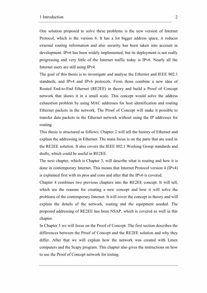
ISO’s OSI model is used when different layers are talked about in networking.
OSI-model has seven layers, which are, from bottom to top, Physical, Data link,
Network, Transport, Session, Presentation and Application layers. The idea with
this layered model is that a layer offers services for the upper layers and receives
services from the layer below it. Together they form a working unit. OSI model is
not used so much as the TCP/IP model is mainly used for designing protocols for
today’s Internet. TCP/IP model has 4 or 5 layers depending if the Data link layer
is divided into 2 layers or not. New protocols are usually hard to fit to the OSI
model because they are designed for the TCP/IP model. Figure 2-1 shows both
models and how their layers correspond to each other.
2 Ethernet and IEEE 802.1
5
Figure 2-1: OSI model vs. TCP/IP model
The reason for explaining these layers is that the structure of this thesis is partly
based on the order of layers. Ethernet is located on OSI layer 2, which is the Data
Link layer. The next chapter will be about IPv4 and IPv6, which can be found
from the OSI layer 3, also known as Network layer. In this thesis all the
references to different layers will be referring to the OSI model, if nothing else is
mentioned.
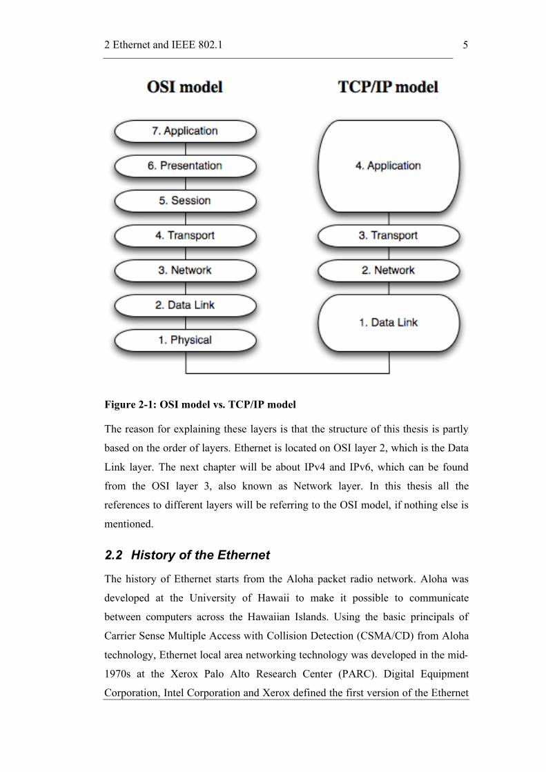
2.2 History of the Ethernet
The history of Ethernet starts from the Aloha packet radio network. Aloha was
developed at the University of Hawaii to make it possible to communicate
between computers across the Hawaiian Islands. Using the basic principals of
Carrier Sense Multiple Access with Collision Detection (CSMA/CD) from Aloha
technology, Ethernet local area networking technology was developed in the mid-
1970s at the Xerox Palo Alto Research Center (PARC). Digital Equipment
Corporation, Intel Corporation and Xerox defined the first version of the Ethernet
2 Ethernet and IEEE 802.1
6
standard in 1978. It was the standard for 10-Mbps Ethernet that formed the basis
for IEEE 802.3 standard. [Pet+00]
2.3 Ethernet Frame Format
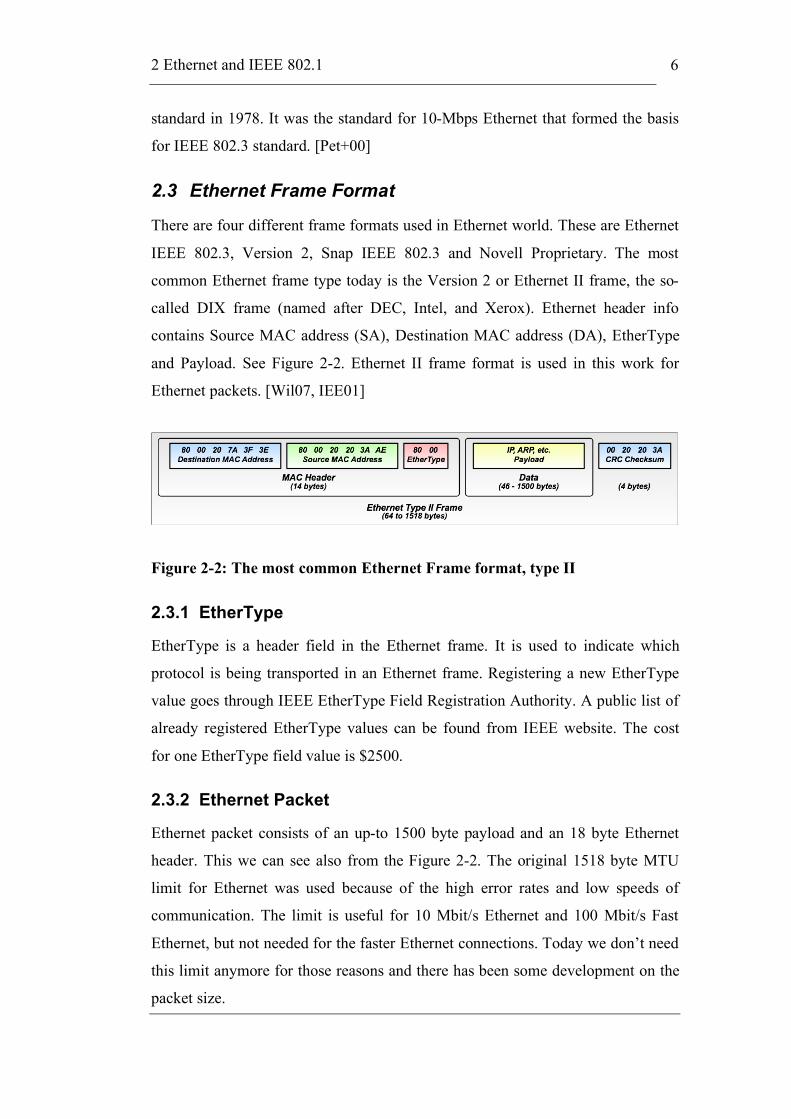
There are four different frame formats used in Ethernet world. These are Ethernet
IEEE 802.3, Version 2, Snap IEEE 802.3 and Novell Proprietary. The most
common Ethernet frame type today is the Version 2 or Ethernet II frame, the so-
called DIX frame (named after DEC, Intel, and Xerox). Ethernet header info
contains Source MAC address (SA), Destination MAC address (DA), EtherType
and Payload. See Figure 2-2. Ethernet II frame format is used in this work for
Ethernet packets. [Wil07, IEE01]
Figure 2-2: The most common Ethernet Frame format, type II
2.3.1 EtherType
EtherType is a header field in the Ethernet frame. It is used to indicate which
protocol is being transported in an Ethernet frame. Registering a new EtherType
value goes through IEEE EtherType Field Registration Authority. A public list of
already registered EtherType values can be found from IEEE website. The cost
for one EtherType field value is $2500.
2.3.2 Ethernet Packet
Ethernet packet consists of an up-to 1500 byte payload and an 18 byte Ethernet
header. This we can see also from the Figure 2-2. The original 1518 byte MTU
limit for Ethernet was used because of the high error rates and low speeds of
communication. The limit is useful for 10 Mbit/s Ethernet and 100 Mbit/s Fast
Ethernet, but not needed for the faster Ethernet connections. Today we don’t need
this limit anymore for those reasons and there has been some development on the
packet size.

2 Ethernet and IEEE 802.1
7
2.3.2.1 Jumbo Frames
Ethernet jumbo frames are Ethernet packets, which have a larger payload than
1500 bytes. They can carry up to 9000 bytes of payload. Most of the Gigabit
Ethernet switches and Gigabit Ethernet network interface cards (NICs) already
support jumbo frames, but all slower equipment only support the standard sized
packets. Jumbo frames are not recognised by the IEEE 802 standards committee,
because using them would remove the interoperability with other 802 protocols.
In IP subnetworks all the hosts must have an identical MTU. This means that
interfaces, which are using jumbo frames, cannot be in the same subnet with
interfaces using standard sized frames.
Reason for this 9000-byte payload comes from the fact that Ethernet uses a 32-bit
CRC that loses its effectiveness above about 12000 bytes. There would be a need
for even bigger payloads, but it is not easy to change the 32-bit CRC limit. In
comparison, the IPv4 packet size limit is 64 KiB and in IPv6 it is already 4 GiB.
2.4 MAC Address
Media Access Control (MAC) addresses are used in networks for identifying the
devices in the network. They are unique identifiers for every network adapter
(NICs). In some cases it can also be set by hand for certain reasons. The identifier
format is called EUI-48 or better known as MAC-48 address. The standard format
for printing EUI-48 addresses in human-readable media is six groups of two
hexadecimal digits in transmission order. They can be separated by hyphens (-) or
by colons (:), e.g. 01-23-45-67-89-ab or 01:23:45:67:89:ab.
The MAC address contains a three-octet Organizational Unique Identifier (OUI)
part, which is usually the vendor identifier. The latter three octets are used for
identifying the exact device. For example MAC address 00:0d:93:b0:ad:aa
contains OUI part 00:0d:93, which tells that the vendor is Apple Computer. This
shows that MAC addresses do not contain any hierarchy in the addresses. The
lack of hierarchy lowers the scalability of MAC address usage to smaller
networks. Worldwide networks need to have hierarchy in addresses for efficient
routing to be possible.

2 Ethernet and IEEE 802.1
8
2.4.1 Extended Unique Identifier – EUI
EUI addresses contain two parts, which are Organizational Unique Identifier
(OUI) and extension identifier parts. There are three different EUI formats, which
are EUI-48, EUI-60 and EUI-64. In Table 2.1 are these different formats
explained.
Table 2.1: Extended Unique Identifier formats
Identifier EUI-48 EUI-60 EUI-64
OUI 24-bit 24-bit 24-bit
Extension 24-bit 36-bit 40-bit
Addresses FF:FF:FF:FF:FF:FF FF-FF-FF:F.F.F.F.F.F.F.F.F FF:FF:FF:FF:FF:FF:FF:FF
EUI-60 was used before for World Wide Name (WWN) identifier, but should not
be used anymore. It is recommended to use EUI-64 identifiers instead of EUI-60.
2.5 MAC Address Scalability Issues
Layer 2 switches refresh periodically their source MAC address tables in a
bridged network. In a case where the number of MAC addresses is really big,
MAC address learning could create broadcast storms or latency problems [Rivxx].
Even splitting the network into separate domains using VLANs, some customers
might have a lot of Ethernet NICs spread all over the WAN. Efficient methods to
optimise the MAC address learning are needed.
This 48-bit address space contains potentially 248 or 281,474,976,710,656 possible
MAC addresses. The IEEE expects the EUI-48 space to be exhausted no sooner
than the year 2100; EUI-64s are not expected to run out in the foreseeable future.
So using either EUI-48 or EUI-64 solves the exhaustion of addresses. From this
we can see that the address space is big enough to scale for the needs of Internet,
but the hierarchy is missing from the basic MAC address.

2 Ethernet and IEEE 802.1
9
2.6 Address Translation
Address Resolution Protocol (ARP) is a protocol used for mapping a network-
layer address to a hardware address like IP address to MAC address. There is also
a Reverse ARP (RARP), which maps a hardware address to a network-layer
address. Figure 2-3 shows the messages used in ARP.
Figure 2-3: ARP message flow
When a client wants to send a packet to another host, it needs to first find out the
MAC address of the other host. This is done with ARP request message, which is
sent using the Ethernet broadcast address and EtherType value 0x806. This
ensures that all the devices in the same collision domain (LAN) will receive the
message. The X.X.X.X and Y.Y.Y.Y are both IP addresses, where the X.X.X.X is
the destination host and Y.Y.Y.Y is the source host. When the destination host
receives the message it will respond with an ARP reply message and all the other
devices will discard the packet.
The ARP reply from the destination host to the source host contains the MAC
address of the destination host. This message is sent directly as a unicast to the
source host using its IP address. There is no need for the destination host to do the
same for the source host, because it got the source host’s MAC address from the
ARP request.

2 Ethernet and IEEE 802.1
10
The need for these two addresses comes from the global Internet. Routing with
MAC addresses does not work in bigger networks like Internet. The reason for
this is the missing hierarchy. IP addresses bring the hierarchy part for routing
purposes. This makes it possible to scale to a worldwide network. But is there
really a need to have two addresses?
2.7 IEEE 802.1 Standards and Drafts
There are some existing IEEE standards, which could be used in RE2EE. These
standards belong to the IEEE 802.1 Working Group and the ones that are
examined here are 802.1Q, 802.1ad and 802.1ah.
To get the needed standards and standard drafts one has to join the IEEE
Standards Association (IEEE-SA) or wait that the standard is over 12 months old.
IEEE-SA Corporate Membership annual costs for a university are $1000. IEEE
and IEEE-SA membership does not give you access to all IEEE Standards and
drafts. Members receive a discount on the purchase of standards and standards
subscriptions. IEEE and IEEE-SA provide the facilities, staff, and resources to
develop standards. The price of the standard you are interested in pays for
intellectual property as well as the time and resources contributed to the standard's
development, much the same as you would pay for the rights to develop projects
using published copyrighted novels, or published copyrighted music, etc.
Please note that membership does not include access to standards drafts. You
must query the working group chair directly for permission to view their drafts,
and the working group will make the decision.
2.7.1 IEEE 802.1 – LAN/MAN Architecture
IEEE 802.1 Working Group is focusing on developing standards for 802
LAN/MAN Architecture, interworking among 802 LANs, MANs and other wide
area networks, 802 Security, 802 overall network management, and protocol
layers above the MAC & LLC layers. The 802.1 working group has four active
task groups: Interworking, Security, Audio/Video Bridging and Congestion
Management.

2 Ethernet and IEEE 802.1
11
2.7.2 IEEE 802.1Q – Virtual LANs
IEEE 802.1Q standard (also known as VLAN Tagging) was developed to make it
possible to separate different departments’ traffic in a common LAN
infrastructure. Separation of the traffic meant that there was no way to
communicate between different VLANs on layer 2. The inter-VLAN
communication needed to be done using layer 3 routers, which typically meant the
need for IP addresses. Support for VLANs made a 2nd tier to network’s hierarchy,
but the network could still only scale to support one company and not global
networks.
These Virtual LANs (VLANs) can be created using a Q-tag (also known as
VLAN ID, VID), which identifies each VLAN from others. Q-tag, which is all
and all a 4-byte field, is added to the normal Ethernet header frame between
Source Address and EtherType fields. [Nor07]
802.1Q uses the EtherType field to identify that this is an 802.1Q frame. Tag
Protocol ID (TPID) value for 802.1Q is 0x8100 and it is inserted to the EtherType
field. After TPID there is a Tag Control Information field (TCI), which is two-
bytes long. It is divided to three parts, which are Priority Code Point (PCP),
Canonical Format Indicator (CFI) and VID.
Figure 2-4: Tag Control Information field in IEEE 802.1Q [IEE05]
PCP is a 3-bit field, which sets the priority level for the packet. More about the
priority levels can be found from IEEE 802.1p. Next field, the CFI is a 1-bit
indicator, which is always set to zero for Ethernet switches. CFI is used for
compatibility between Ethernet and Token Ring networks. VID field specifies the
VLAN to which the frame belongs. After TCI there is another two-bytes field
containing the frame’s original EtherType. [IEE05]
2 Ethernet and IEEE 802.1
12
IEEE-SA Standards Board approved IEEE 802.1Q as an IEEE standard on
December 8th 2005 and it was published May 19th 2006. American National
Standards Institute approved it as an ANSI standard on March 28th 2006.
2.7.3 IEEE 802.1ad – Provider Bridges
IEEE 802.1ad standard (also known as Q-in-Q, stacked VLANs or Provider
Bridges) is an amendment to IEEE 802.1Q standard. It adds a new Q-tag that
allows the service provider to administer their own tags to identify individual
customer networks, while the first (original) Q-tag is used to identify VLANs
within the customer’s network. Although Q-in-Q supports three-tiered hierarchy,
the service provider can still only create 4 094 customer VLANs. Q-in-Q tagging
enlarged the scaling of the network, but still the supported amount of users in one
VLAN was not enough to make it scale to a worldwide network.
The inner tag field or C-tag carries the customer VLAN identifier (C-VID), which
identifies a customer VLAN (C-VLAN). The outer tag field, or S-tag carries the
S-VID, which identifies a service VLAN (S-VLAN). Spanning tree protocol is
used to prevent loops in each S-VLAN. [TPA06]
IEEE-SA Standards Board approved IEEE 802.1ad as an IEEE standard on
December 8th 2005 and it was published May 26th 2006. American National
Standards Institute approved it as an ANSI standard on March 28th 2006.
2.7.4 IEEE 802.1ah – Provider Backbone Bridges
The scope of IEEE 802.1ah standard (also known as MAC-in-MAC or Provider
Backbone Bridges (PBB)) is to define an architecture and bridge protocols
compatible and interoperable with Provider Bridged Network (IEEE 802.1ad)
protocols. This would allow interconnection between multiple Provider Bridged
Networks and increase the number of supported VLANs in the network. IEEE
802.1ah is still a draft and the newest draft (version 4.0) was released on
November 22nd 2007.
802.1ah allows for layering the Ethernet network into customer and provider
domains with complete isolation among their MAC addresses. It encapsulates the
customer MAC header with a service provider MAC header. The standard uses a
24-bit service tag in the service provider MAC header instead of the additional Q-

2 Ethernet and IEEE 802.1
13
tag used in 802.1ad. The new service tag makes it possible to support a theoretical
maximum of 16 million service instances. In IEEE 802.1ah enabled networks the
service provider and the end customer domains are treated as separate.
Interconnection between the Provider Bridged Networks allows this architecture
to have enough hierarchy levels to scale to a global network. This architecture still
uses Spanning Tree Protocol (STP) to prevent forwarding loops. Use of STP
results in inefficient routing, because some links are not used at all and some
might be congested at the same time. More about STP in the end of this chapter.
802.1ah defines B-DA and B-SA to indicate the Backbone Destination Address
and Backbone Source Address and also introduces B-VID (Backbone VLAN ID).
Client Ethernet frames are encapsulated and forwarded based on these new
frames. I-SID (Service Instance ID) tag field is 24-bit and is proposed as a
solution to the space limitations encountered with the 12-bit S-VID defined in
802.1ad. [Nor07, TPA06]
Figure 2-5: Development of Ethernet headers [Nor07]
Figure 2-5 shows the development of Ethernet headers from IEEE 802.1 to IEEE
802.1ah.
2 Ethernet and IEEE 802.1
14
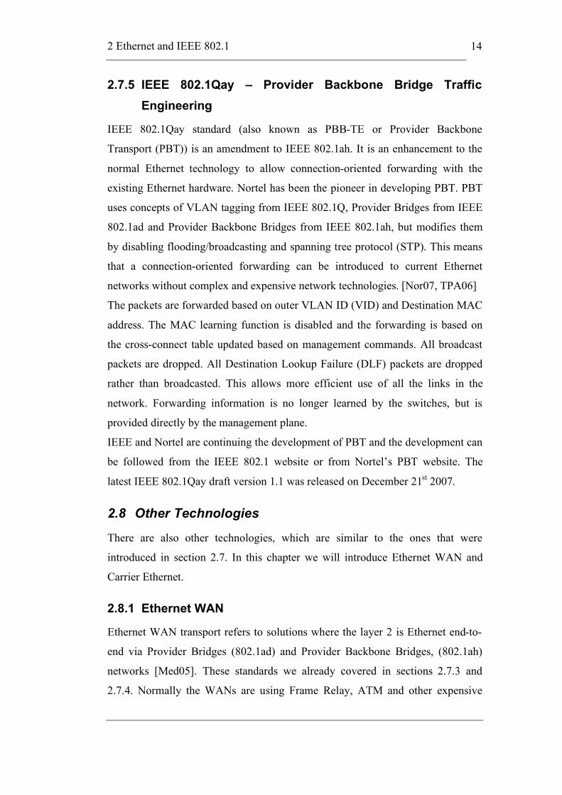
2.7.5 IEEE 802.1Qay – Provider Backbone Bridge Traffic
Engineering
IEEE 802.1Qay standard (also known as PBB-TE or Provider Backbone
Transport (PBT)) is an amendment to IEEE 802.1ah. It is an enhancement to the
normal Ethernet technology to allow connection-oriented forwarding with the
existing Ethernet hardware. Nortel has been the pioneer in developing PBT. PBT
uses concepts of VLAN tagging from IEEE 802.1Q, Provider Bridges from IEEE
802.1ad and Provider Backbone Bridges from IEEE 802.1ah, but modifies them
by disabling flooding/broadcasting and spanning tree protocol (STP). This means
that a connection-oriented forwarding can be introduced to current Ethernet
networks without complex and expensive network technologies. [Nor07, TPA06]
The packets are forwarded based on outer VLAN ID (VID) and Destination MAC
address. The MAC learning function is disabled and the forwarding is based on
the cross-connect table updated based on management commands. All broadcast
packets are dropped. All Destination Lookup Failure (DLF) packets are dropped
rather than broadcasted. This allows more efficient use of all the links in the
network. Forwarding information is no longer learned by the switches, but is
provided directly by the management plane.
IEEE and Nortel are continuing the development of PBT and the development can
be followed from the IEEE 802.1 website or from Nortel’s PBT website. The
latest IEEE 802.1Qay draft version 1.1 was released on December 21st 2007.
2.8 Other Technologies
There are also other technologies, which are similar to the ones that were
introduced in section 2.7. In this chapter we will introduce Ethernet WAN and
Carrier Ethernet.
2.8.1 Ethernet WAN
Ethernet WAN transport refers to solutions where the layer 2 is Ethernet end-to-
end via Provider Bridges (802.1ad) and Provider Backbone Bridges, (802.1ah)
networks [Med05]. These standards we already covered in sections 2.7.3 and
2.7.4. Normally the WANs are using Frame Relay, ATM and other expensive
2 Ethernet and IEEE 802.1
15
technologies. The are many reasons for using Ethernet instead of ATM, which for
example include easier maintenance, scalability and low cost of investment.
2.8.2 Carrier Ethernet
Metro Ethernet Forum (MEF) was formed in 2001 to develop a possibility to
bring Ethernet to Wide Area Network. The development resulted into the creation
of Carrier Ethernet. Carrier Ethernet is a carrier-class service defined by five key
attributes that distinguish Carrier Ethernet from familiar LAN based Ethernet.
These attributes are standardised services, scalability, reliability, quality of service
and service management. Carrier Ethernet services are based on the Ethernet
standard and they cover a metropolitan area. Subscribers and businesses use
Carrier Ethernet to connect to a WAN. Advantages in using Ethernet-based access
network in Metropolitan Area Network (MAN) are the cost and adaptability to the
existing LAN. [MEF07]
2.9 Spanning Tree Protocol
Spanning Tree Protocol (STP) is used for routing in Ethernet networks. It is
defined in the IEEE 802.1D Standard. IEEE 802.1D Standard’s name is MAC
Bridges. The first version of 802.1D standard was released in 1990 and the 2nd
version came out in 1998. These versions had the original Spanning Tree Protocol
specification in them. The newest version of the standard was released in 2004
and it removed the original STP and replaced it with Rapid Spanning Tree
Protocol (RSTP). This newer protocol will be explained briefly in section 2.9.1.
Spanning Tree Protocol runs on layer 2 and ensures a loop free topology for any
bridged LAN. It creates a spanning tree within a mesh network of connected
layer-2 bridges. In the creation process it disables all the links, which are not part
of the tree, leaving a single active path between any two network nodes. Layer 2
bridges are typically Ethernet switches. When an active link fails, it automatically
finds a redundant link to replace the broken one. This works well in a LAN
environment, but when the network is bigger or has Virtual LANs in it, there is a
need for better protocols.
The protocol operation is explained briefly here. There are three main components
in the STP operation, which are root bridge, root port and designated port. In the

2 Ethernet and IEEE 802.1
16
beginning of the process the bridge with smallest bridge ID is elected as the root
bridge. After this all the bridges determine their least cost path to the root and
inform the root bridge about it. From these the root bridge selects the one with
smallest cost and the port connected to that path becomes the root port.
Designated ports are selected by determining the least cost path from each
network segment to the root bridge. Any active port that is not a root port or a
designated port is a blocked port. [IEE04]
2.9.1 IEEE 802.1w – Rapid Spanning Tree Protocol (RSTP)
Rapid Spanning Tree Protocol was introduced in 1998 in IEEE 802.1w Standard.
The newest version is from 2004 when it was merged to IEEE 802.1D Standard. It
supersedes the older STP. The actual name of the IEEE 802.1w Standard is Rapid
Reconfiguration of Spanning Tree.
The main difference in RSTP to STP is that it can recover from link failures a lot
faster, hence the name Rapid STP. This was a big weakness in the STP. RSTP
still supports equipment using original STP or Multiple Spanning Tree Protocol
(MSTP), which makes it easier to implement this protocol to old networks without
updating all the devices. [IEE04]
In RSTP there are five different roles for the bridge ports. These are root,
designated, alternate, backup and disabled. The root bridge port is a forwarding
port, which has been elected for the spanning-tree topology, designated port is a
forwarding port for every LAN segment, alternate port is an alternate path to the
root bridge and does not use the root port, backup port is a redundant path to a
segment where another bridge port already connects and disabled is a port, which
has been disabled manually. The two new ones in RSTP are alternate and backup
ports.
These new functionalities improve the performance of the STP, but still they are
not enough to make Ethernet networks scale properly. Saad Abuguba and István
Moldován measured convergence and scalability of RSTP and proved that
convergence of RSTP is inadequate for carrier-grade services [Abu+06].

2 Ethernet and IEEE 802.1
17
2.9.2 IEEE 802.1s – Multiple Spanning Tree Protocol (MSTP)
Multiple Spanning Tree Protocol (MSTP) was originally defined in IEEE 802.1s
and later merged into IEEE 802.1Q Standard in 2003. The protocol is an
extension to RSTP to develop usefulness of the Virtual LANs. It makes possible
to use separate spanning trees for different VLANs. This allows the usage of
redundant links and balance the traffic to the whole network. The actual name of
the IEEE 802.1s Standard is Multiple Spanning Trees.
A Multiple Spanning Tree region (MST) comprises multiple physically
interconnected MSTP-enabled switches and the corresponding network segments
connected to these switches. These switches have the same region name, the same
VLAN-to-spanning-tree mapping configuration and the same MSTP revision
level. A switched network can contain multiple MST regions. You can group
multiple switches into one MST region by using the corresponding MSTP
configuration commands.
A Multiple Spanning Tree Instance (MSTI) refers to a spanning tree in a MST
region. Multiple spanning trees can be established in one MST region. These
spanning trees are independent of each other.
A spanning tree in an MST region is called an Internal Spanning Tree (IST). ISTs
together with the Common Spanning Tree (CST) form the Common and Internal
Spanning Tree (CIST) of the entire switched network. An IST is a special MSTI;
it belongs to an MST region and is a branch of CIST.
A CST is the spanning tree in a switched network that connects all MST regions
in the network. If you regard each MST region in the network as a switch, then
the CST is the spanning tree generated by STP or RSTP running on the
"switches". A CIST is the spanning tree in a switched network that connects all
switches in the network. It comprises the ISTs and the CST.
MST regions, the other STP bridges and LANs are interconnected using one
single Common Spanning Tree (CST). MSTP is compatible with RSTP and STP,
and these regions can use any of these spanning tree versions. [IEE02, IEE05]

3 Routing in The Internet
18
3 Routing in The Internet
This chapter contains the background information to the Internet Protocol (IP) and
how routing is done today in Internet. At the moment the Internet uses mainly IP
version 4 addresses, but this chapter will also cover the newer version of the
Internet Protocol. This knowledge is vital in understanding the need for the new
style of addressing and the problems that it will solve from contemporary Internet.
This chapter also tells what was the key feature that made IPv4 spread so well that
it became the de facto standard addressing for the Internet.
3.1 Internet Protocol Version 4 Networks
IPv4 was developed based on the earlier versions of the Internet Protocol. Today
it is the dominant network layer protocol on the Internet. IETF RFC 791 standard
specifies the main parts of the protocol. It has been developed a lot since the 1981
when the standard was published the first time.
3.1.1 Internet Protocol Version 4 Addresses
IPv4 addresses are used in Internet as the global addressing scheme. The address
space is hierarchical which means that it contains different parts that correspond
to the hierarchy in the network. IPv4 address consists of two parts, which are
network part and host part. Network part identifies which network the host
belongs to and the host part identifies the exact host in that network. IPv4
addresses are divided into five classes. Figure 3-1 shows the different classes and
how they are formed. [Pet+00, Pos81]
3 Routing in The Internet
19
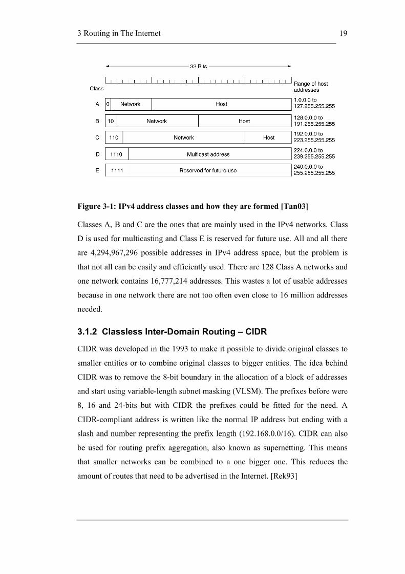
Figure 3-1: IPv4 address classes and how they are formed [Tan03]
Classes A, B and C are the ones that are mainly used in the IPv4 networks. Class
D is used for multicasting and Class E is reserved for future use. All and all there
are 4,294,967,296 possible addresses in IPv4 address space, but the problem is
that not all can be easily and efficiently used. There are 128 Class A networks and
one network contains 16,777,214 addresses. This wastes a lot of usable addresses
because in one network there are not too often even close to 16 million addresses
needed.
3.1.2 Classless Inter-Domain Routing – CIDR
CIDR was developed in the 1993 to make it possible to divide original classes to
smaller entities or to combine original classes to bigger entities. The idea behind
CIDR was to remove the 8-bit boundary in the allocation of a block of addresses
and start using variable-length subnet masking (VLSM). The prefixes before were
8, 16 and 24-bits but with CIDR the prefixes could be fitted for the need. A
CIDR-compliant address is written like the normal IP address but ending with a
slash and number representing the prefix length (192.168.0.0/16). CIDR can also
be used for routing prefix aggregation, also known as supernetting. This means
that smaller networks can be combined to a one bigger one. This reduces the
amount of routes that need to be advertised in the Internet. [Rek93]
3 Routing in The Internet
20
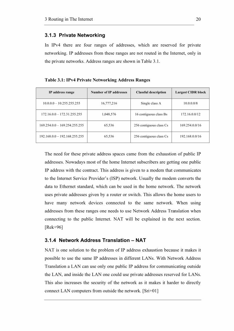
3.1.3 Private Networking
In IPv4 there are four ranges of addresses, which are reserved for private
networking. IP addresses from these ranges are not routed in the Internet, only in
the private networks. Address ranges are shown in Table 3.1.
Table 3.1: IPv4 Private Networking Address Ranges
IP address range Number of IP addresses Classful description Largest CIDR block
10.0.0.0 – 10.255.255.255 16,777,216 Single class A 10.0.0.0/8
172.16.0.0 – 172.31.255.255 1,048,576 16 contiguous class Bs 172.16.0.0/12
169.254.0.0 – 169.254.255.255 65,536 256 contiguous class Cs 169.254.0.0/16
192.168.0.0 – 192.168.255.255 65,536 256 contiguous class Cs 192.168.0.0/16
The need for these private address spaces came from the exhaustion of public IP
addresses. Nowadays most of the home Internet subscribers are getting one public
IP address with the contract. This address is given to a modem that communicates
to the Internet Service Provider’s (ISP) network. Usually the modem converts the
data to Ethernet standard, which can be used in the home network. The network
uses private addresses given by a router or switch. This allows the home users to
have many network devices connected to the same network. When using
addresses from these ranges one needs to use Network Address Translation when
connecting to the public Internet. NAT will be explained in the next section.
[Rek+96]
3.1.4 Network Address Translation – NAT
NAT is one solution to the problem of IP address exhaustion because it makes it
possible to use the same IP addresses in different LANs. With Network Address
Translation a LAN can use only one public IP address for communicating outside
the LAN, and inside the LAN one could use private addresses reserved for LANs.
This also increases the security of the network as it makes it harder to directly
connect LAN computers from outside the network. [Sri+01]

3 Routing in The Internet
21
There are different types of NAT behaviours, which are explained briefly in the
next sections.
3.1.4.1 Address and Port Mapping
In Endpoint-Independent Mapping, the NAT reuses the port mapping for
subsequent packets sent from the same internal IP address and port to any external
IP address and port.
In Address-Dependent Mapping, the NAT reuses the port mapping for subsequent
packets sent from the same internal IP address and port to the same external IP
address, regardless of the external port.
In Address and Port-Dependent Mapping, the NAT reuses the port mapping for
subsequent packets sent from the same internal IP address and port to the same
external IP address and port while the mapping is still active. [Aud+07]
3.1.4.2 IP Address Pooling Behaviour
Some NATs are capable of assigning IP addresses from a pool of IP addresses on
the external side of the NAT, as opposed to just a single IP address. If one internal
IP address is mapped to multiple external IP addresses, then the IP address
pooling behaviour used is Arbitrary. The other behaviour is called Paired and in
that one internal IP address is mapped to one external IP address. It is
recommended to Paired behaviour is available. [Aud+07]
3.1.4.3 Port Assignment Behaviour
Port Assignment can use Port preservation, Port overloading or No port
preservation as the behaviour. Port preservation attempts to preserve the port
number used internally when assigning a mapping to an external IP address and
port. NAT using Port overloading behaviour uses port preservation even in a case
of collision. Most applications will fail if the NAT uses Port overloading. A NAT
that does not attempt to make the external port numbers match the internal port
numbers in any case is referred to as No port preservation. [Aud+07]
3.1.4.4 Port Parity
Some NATs use Port Parity behaviour, which means that an odd port is mapped to
an odd port, and an even port is mapped to an even port. This is only used with

3 Routing in The Internet
22
UDP ports. Preserving the port parity allows for supporting communication with
peers that do not support explicit specification of both RTP and RTCP port
numbers. This behaviour respects the rule that RTP use even ports, and RTCP use
odd ports. [Aud+07]
3.1.4.5 Port Contiguity
Some NATs attempt to preserve the port contiguity rule where RTCP port number
is always the RTP port number added with one. Supporting port contiguity is in
many cases not practical, because NAT cannot reliably distinguish between RTP
over UDP and other UDP packets where there is no contiguity rule. [Aud+07]
3.1.4.6 Filtering Behaviour
NAT assigns a filtering rule for the mapping between an internal IP:port and
external IP:port tuple, when an internal endpoint opens an outgoing session
through a NAT. There are three main filtering behaviours explained in this
section.
Endpoint-Independent Filtering forwards only packets destined to the internal
address and port, regardless of the external IP address and port source. In other
words, sending packets from the internal side of the NAT to any external IP
address is sufficient to allow any packets back to the internal endpoint.
Address-Dependent Filtering filters out packets not destined to the internal
address and port. Additionally, the NAT will filter out packets from external
address destined for the internal endpoint if that endpoint has not sent packets to
that external address previously, no matter to which port. In other words, for
receiving packets from a specific external endpoint, it is necessary for the internal
endpoint to send packets first to that specific external endpoint's IP address.
Address and Port-Dependent Filtering is similar to the previous behaviour, except
that the external port is also relevant. For receiving packets from a specific
external endpoint, it is necessary for the internal endpoint to send packets first to
that external endpoint's IP address and port. [Aud+07]
3.1.4.7 Hairpinning Behaviour
Hairpinning allows two endpoints on the internal side of the NAT to communicate
even if they only use each other's external IP addresses and ports. [Aud+07]
3 Routing in The Internet
23
3.1.4.8 Pros and Cons of NAT
When NAT was introduced there were a lot of discussion about its way of
destroying the end-to-end principle of Internet. Jerry Saltzer, David Reed and
Dave Clark introduced this principle in 1984 [Sal+84]. Lack of end-to-end
principle is truly a drawback in NAT and causes that some Internet protocols do
not work well over NAT.
NAT breaks the global addressability because hosts and services don’t have
anymore globally unique addresses for communication. These IP addresses were
used as an identity before and with this identity most of the applications were
communicating.
On the other hand this lack of full bidirectional connectivity can be seen as a
feature. It actually created more security for the hosts, because hosts outside the
private network cannot initiate a connection to hosts behind NAT. Many NAT-
enabled firewalls use this as the core of the protection they provide.
But still the biggest benefit of NAT is that it postponed the exhaustion date of
IPv4 addresses. Now networks, which needed a class B IP range or a block of
class C network addresses, can be connected to the Internet with as little as a
single IP address.
Recently Dave Clark formulated a new principle: “A function can only be
implemented fully and correctly when the data concerning an application or the
application itself is located in a place where it can be reliably operated.” This is
called trust-to-trust principle and Clark gave with this principle his blessing to all
the devices breaking the end-to-end principle. [CSC07]
3.1.5 Application Level Gateway
Application Level Gateway (ALG) is a security component inside a firewall or a
NAT. It allows the usage of various protocols that normally would be blocked by
a firewall or needing special configurations to work with NAT. Typical protocols
that benefits from ALG are SIP, Instant Messengers (IM), RTSP and BitTorrent.
In order for these protocols to work through NAT or a firewall, either the NAT
has to monitor the control traffic and open up port mappings dynamically as
required, or the application has to know about an address/port number
combination that allows incoming packets.

3 Routing in The Internet
24
ALG offers for these protocols a possibility for the clients to use dynamic
TCP/UDP ports to communicate with the known ports used by the server
applications. Without ALG the ports would get blocked or the ports need to be
explicitly opened in the firewall. ALG can also convert the network layer address
information found inside an application payload, so that the addresses are
acceptable on both sides of the firewall/NAT.
3.1.6 Allocating an IPv4 Network Address
In IPv4 networks clients get their IP addresses usually dynamically from the
DHCP (Dynamic Host Control Protocol) server. When a client is plugged to the
network, it sends a request for an IP address. Figure 3-2 shows the flow of
messages in the registration to the DHCP server.
Figure 3-2: Client-server interaction - allocating a network address

3 Routing in The Internet
25
Client first sends a broadcast message called DHCPDiscover to find all the DHCP
servers. Server responds to client’s MAC address with a DHCPOffer message to
inform which services it offers. Client then selects from all the DHCPOffer
messages it got, the one that it starts to use and broadcasts the information in a
DHCPRequest message. All the DHCP servers get this message, but only the
selected one replies with a DHCPAck message. The others withdraw their
DHCPOffer messages. [Dro97]
IP addresses can also be set manually without a DHCP server. Then the IP address
is static. This can be the case in a smaller network, where it is possible to handle
the addresses by hand. Servers also nearly always have static IP addresses, so that
clients can connect to them easily.
3.2 Internet Protocol Version 6 Networks
Internet Protocol version 6 was developed to fix the problems we are having with
the IPv4. The main change is a bigger address space, but also many other changes
have been made. It is specified in the RFC 2460, which was released in December
1998.
3.2.1 Internet Protocol Version 6 Addresses
As mentioned earlier the main difference between IPv6 and IPv4 is that the
address space is much larger. IPv6 addresses are 128 bits long, which gives us a
total of 3.4 *1038 addresses. That is 7.9 *1028 times more addresses than in IPv4
address space. Also, this means that every person in the whole world would have
about 5 *1028 addresses for them to use. Still the intention of IPv6 designers was
not to give a permanent unique address for every person. The large address space
with hierarchical addresses ensures the scalability to be better than with IPv4.
An IPv6 address contains normally a 64-bit network prefix and a 64-bit host part.
The preferred form of the address is x:x:x:x:x:x:x:x, where the letter x stands for a
4-digit hexadecimal number. There are 8 of these 16-bit numbers, which make the
address 128 bits long. Addresses are written like
0123:4567:89ab:cdef:0123:4567:89ab:cdef. [Hin+06]
The hierarchy is created using Regional Internet Number Registries (RIRs). RIRs
replaced the use of Top Level Aggregator (TLA) / Next Level Aggregator (NLA)
3 Routing in The Internet
26
schemes defined in RFC 2374, "An IPv6 Aggregatable Global Unicast Address
Format". Address format consists of global routing prefix, subnet ID and interface
ID. Global routing prefix is a value assigned to a site, subnet ID is an identifier for
the subnet of the site and interface ID identifies the exact device. RIRs and ISPs
create the hierarchical structure for the global routing prefix and site
administrators create the hierarchical structure for the subnet ID field. [Hin+03]
3.2.2 Classless Inter-Domain Routing in IPv6
CIDR is not needed in IPv6 because of the larger address space and also because
it was designed for fully classless addressing, but CIDR is supported though. It
can be used in IPv6 addresses, where the prefix length can range from 0 to 128,
due to the larger number of bits in the address. CIDR in IPv6 uses the same syntax
as in IPv4 and after the slash the number represents the amount of significant bits.
3.2.3 Private Networking and NAT in IPv6
IPv6 does not offer private network features such as NAT. This is also because of
the larger address space in IPv6 compared to IPv4. But there is an address range
for local IPv6 unicast addresses. This address range is identified by the FC00::/7
prefix and the addresses are called Unique Local IPv6 Unicast Addresses. More
information can be found in RFC 4193. [Hin+05]
3.2.4 Allocating an IPv6 Network Address
IPv6 hosts can use Stateless Address Autoconfiguration (SLAAC), which
configures the hosts automatically to a routed IPv6 network. For this SLAAC uses
ICMP for IPv6 (ICMPv6) router discovery message. Host sends a link-local
multicast router solicitation request to get the configuration parameters when it’s
first connected to the network. If the parameters are suitable, routers reply with a
router advertisement packet that contains network-layer configuration parameters.
Stateless Address Autoconfiguration is only suitable for hosts. If the
autoconfiguration does not work or is not configured, a host can use stateful
configuration with DHCPv6 or be configured manually. This is done like in IPv4.
[Tho+07]
3 Routing in The Internet
27
3.3 Packet Delivery Methods in Networks
There are four different types of packet delivery methods in networks, which are
unicast, broadcast, multicast and anycast. These terms are used in this thesis so a
short explanation of each term is needed.
Unicast identifier is the most commonly used in the Internet and it delivers a
message to a single specified destination node. The opposite of unicast is
broadcast. In broadcast a message is sent to all the nodes in the network. IPv6
does not have broadcast addresses; they are replaced by multicast addresses.
Multicast identifier sends a message to all the nodes that have informed the
network that they want to receive multicast messages. It sends the message only
once and in the most efficient way. Only creating copies of the message when the
links to destinations split. Multicast is part of the base specification in IPv6, not
like in IPv4 where it was introduced later. Anycast introduces an identifier for a
set of nodes. A packet sent to an anycast address is delivered to anyone of these
nodes in the group.
3.4 Routing Explained
Routing and forwarding are in many cases mixed up with each other. The main
distinction is that forwarding consists of taking a packet, looking at its destination
address, consulting a table and sending the packet in the direction determined by
that table. Where as routing is the process where the routing tables are built.
Forwarding is actually an easy process compared to routing, which is a process
requiring complex distributed algorithms. Routing algorithms are an on going
development field.
Network devices that usually contain routing functionalities are routers, bridges,
gateways, firewalls and switches. Forwarding tables and routing tables are
different things, but can actually be located in the same data structure. Forwarding
table is used when a packet is being forwarded and the destination interface needs
to be selected. The routing table is the table built up by the routing algorithms and
it is used to build up the forwarding table. It generally contains mappings from
network numbers to next hops. [Pet+00]
Routing tables are created by hand or using routing protocols. There are several
problems with static routing, which include the following: It does not handle node
3 Routing in The Internet
28
or link failures, it does not recognise new nodes or links and it does not allow easy
changes in link costs. To solve these problems one can use routing protocols,
which provide a distributed and dynamic solution. Distribution is the key feature
to make the network scale properly. Static routing can be used in smaller
networks where it is possible to handle the network. In larger networks one needs
to use dynamic routing for avoiding network failures and blockages.
3.4.1 Routing Algorithms
In routing there are many ways to distribute the topology of the network. Two
major classes of routing algorithms are distance vector algorithms and link state
algorithms. These two algorithms classes are explained briefly later.
Routing can also be divided to intra-domain routing and inter-domain routing.
Intra-domain routing is used inside an autonomous system (AS) and intra-domain
routing between different autonomous systems. Intra-domain routing protocols are
also called Interior Gateway Protocols (IGP) and inter-domain routing protocols
are called Exterior Gateway Protocols (EGP). These names come from the
beginning of the Internet when IGP was the intra-domain routing protocol and
EGP was the inter-domain routing protocol, which were used.
3.4.1.1 Distance Vector
The idea of distance vector algorithms is that every node calculates the distances
to all the nodes and then they send this vector to their neighbours. From these
vectors every node can build their own routing table, which then knows the
distance to every node. Common distance vector protocols are Routing
Information Protocol (RIP) and Border Gateway Protocol (BGP). RIP is used in
intra-domain routing. [Pet+00]
BGP is used in inter-domain routing. Every autonomous system has their own
main node, which communicates with the other autonomous systems. This main
node creates a routing table and advertises it to the other main nodes similarly like
RIP works. Instead of advertising distance of the node it advertises the path. BGP
is an example of path vector protocol, which is a subclass of distance vector
protocols. [Sob03]
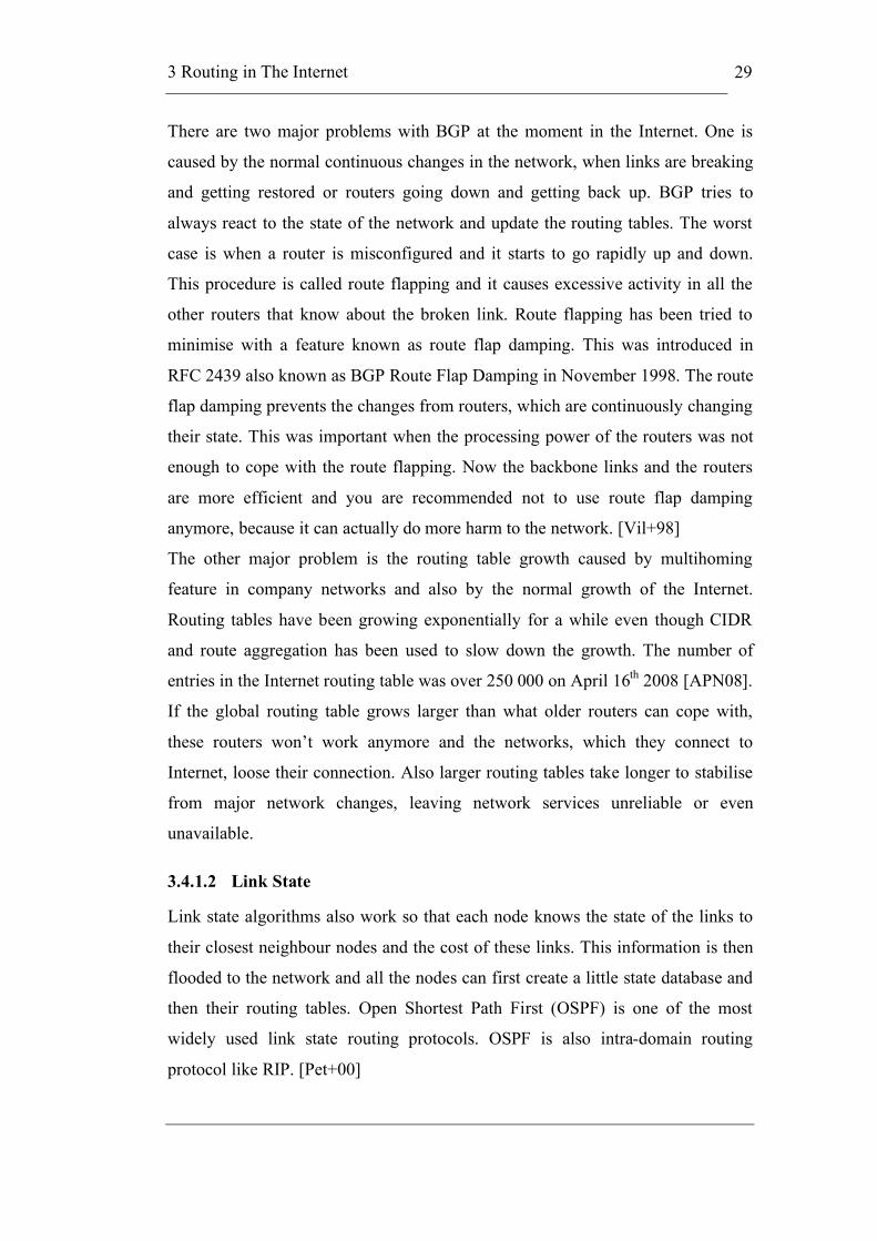
3 Routing in The Internet
29
There are two major problems with BGP at the moment in the Internet. One is
caused by the normal continuous changes in the network, when links are breaking
and getting restored or routers going down and getting back up. BGP tries to
always react to the state of the network and update the routing tables. The worst
case is when a router is misconfigured and it starts to go rapidly up and down.
This procedure is called route flapping and it causes excessive activity in all the
other routers that know about the broken link. Route flapping has been tried to
minimise with a feature known as route flap damping. This was introduced in
RFC 2439 also known as BGP Route Flap Damping in November 1998. The route
flap damping prevents the changes from routers, which are continuously changing
their state. This was important when the processing power of the routers was not
enough to cope with the route flapping. Now the backbone links and the routers
are more efficient and you are recommended not to use route flap damping
anymore, because it can actually do more harm to the network. [Vil+98]
The other major problem is the routing table growth caused by multihoming
feature in company networks and also by the normal growth of the Internet.
Routing tables have been growing exponentially for a while even though CIDR
and route aggregation has been used to slow down the growth. The number of
entries in the Internet routing table was over 250 000 on April 16th 2008 [APN08].
If the global routing table grows larger than what older routers can cope with,
these routers won’t work anymore and the networks, which they connect to
Internet, loose their connection. Also larger routing tables take longer to stabilise
from major network changes, leaving network services unreliable or even
unavailable.
3.4.1.2 Link State
Link state algorithms also work so that each node knows the state of the links to
their closest neighbour nodes and the cost of these links. This information is then
flooded to the network and all the nodes can first create a little state database and
then their routing tables. Open Shortest Path First (OSPF) is one of the most
widely used link state routing protocols. OSPF is also intra-domain routing
protocol like RIP. [Pet+00]

3 Routing in The Internet
30
Intermediate System to Intermediate System (IS-IS) is an IGP routing protocol,
which uses Dijkstra’s algorithm for identifying the best path through the network.
IS-IS does not use IP to carry routing information messages like OSPF does. This
means that IS-IS could be implemented for Ethernet use. [ISO02b]
3.5 Mobile IP
Mobile IP is an Internet Engineering Task Force (IETF) standard communications
protocol that is designed to allow mobile device users to move from one network
to another while maintaining a permanent IP address. Mobile IPv4 is described in
IETF RFC 3344 and updates are added in IETF RFC 4721. The one for IPv6
networks is called Mobile IPv6 and it is described in IETF RFC 3775.
Mobile IPv4 is an add-on to IPv4 and it allows transparent routing of IP packets to
mobile nodes in the Internet. The basic principle of Mobile IPv4 is that each
mobile node is always identified by its home address and if it is located in a
visitor network it is given a care-of address. Care-of address provides information
about its current location. Care-of address is registered to the home agent and the
home agent then sends all the traffic destined for the mobile node through a tunnel
to the care-of address. [Per02]

4 Routed End-to-End Ethernet – RE2EE
31
4 Routed End-to-End Ethernet – RE2EE
In this chapter we combine the two previous chapters into the RE2EE concept. It
explains the reasons for creating a new concept and how it will solve the problems
of the contemporary Internet. This chapter covers the concept in theory and will
explain the details of the network, routing and the equipment needed. The
proposed addressing of RE2EE has been NSAP, which is covered as well in this
chapter.
4.1 About the Concept
The main problem with IPv4 is the address exhaustion. NAT has been a big help
in postponing the problem to the future, but it also created new problems. This is
why IPv6 was developed. It has a lot bigger address space, which provides
enough addresses for the future, but still the deployment of IPv6 has not been
successful. Typical Ethernet networks have the lack of hierarchy problem, which
does not allow them to scale to a global network, even though the address space is
big enough.
The idea behind this Master’s Thesis is to build a Proof of Concept for Routed
End-to-End Ethernet (RE2EE) network. Instead of IP-addresses Routed End-to-
End Ethernet solution will use MAC-addresses as network locators for hosts and
servers. The target is a network that can provide end-to-end services without IP
and with IP and even so that a service can be used through a Routed Ethernet/IP
gateway. Moving from layer 3 to layer 2 means that the technology must have
routing capability to ensure scalability and mobility support. For routing
capability there needs to be hierarchy in the addresses.

4 Routed End-to-End Ethernet – RE2EE
32
Routing protocol for RE2EE could be Intermediate System to Intermediate
System (IS-IS), because IEEE has proposed it for 802.1 and it runs over the
network layer directly without needing IP. In RE2EE network addressing and
address resolution are integral parts of the network. Routing, address resolution
and caching will be dynamic. [Kan+07]
As covered in the Chapter 2 and 3 the MAC addresses won’t be exhausted in the
foreseeable future like IPv4 addresses. In this Proof of Concept EUI-48 identifiers
will be used, but in the future also EUI-64 identifiers could be used. With these
identifiers hierarchy can be added to the network.
4.2 Network Structure
The network structure of RE2EE is shown in Figure 4-1. Network structure
consists of four layers, which are Network Core, Service Core, Mobility Layer
and User Identity Layer. The solution uses the MAC-in-MAC capability that has
been specified in IEEE 802.1ah.
Figure 4-1: RE2EE network structure [Redrawn from Kan+07]
Figure 4-2 illustrates the packet structure used in the RE2EE-solution.
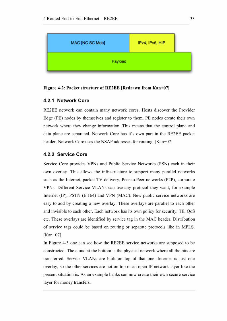
4 Routed End-to-End Ethernet – RE2EE
33
Figure 4-2: Packet structure of RE2EE [Redrawn from Kan+07]
4.2.1 Network Core
RE2EE network can contain many network cores. Hosts discover the Provider
Edge (PE) nodes by themselves and register to them. PE nodes create their own
network where they change information. This means that the control plane and
data plane are separated. Network Core has it’s own part in the RE2EE packet
header. Network Core uses the NSAP addresses for routing. [Kan+07]
4.2.2 Service Core
Service Core provides VPNs and Public Service Networks (PSN) each in their
own overlay. This allows the infrastructure to support many parallel networks
such as the Internet, packet TV delivery, Peer-to-Peer networks (P2P), corporate
VPNs. Different Service VLANs can use any protocol they want, for example
Internet (IP), PSTN (E.164) and VPN (MAC). New public service networks are
easy to add by creating a new overlay. These overlays are parallel to each other
and invisible to each other. Each network has its own policy for security, TE, QoS
etc. These overlays are identified by service tag in the MAC header. Distribution
of service tags could be based on routing or separate protocols like in MPLS.
[Kan+07]
In Figure 4-3 one can see how the RE2EE service networks are supposed to be
constructed. The cloud at the bottom is the physical network where all the bits are
transferred. Service VLANs are built on top of that one. Internet is just one
overlay, so the other services are not on top of an open IP network layer like the
present situation is. As an example banks can now create their own secure service
layer for money transfers.
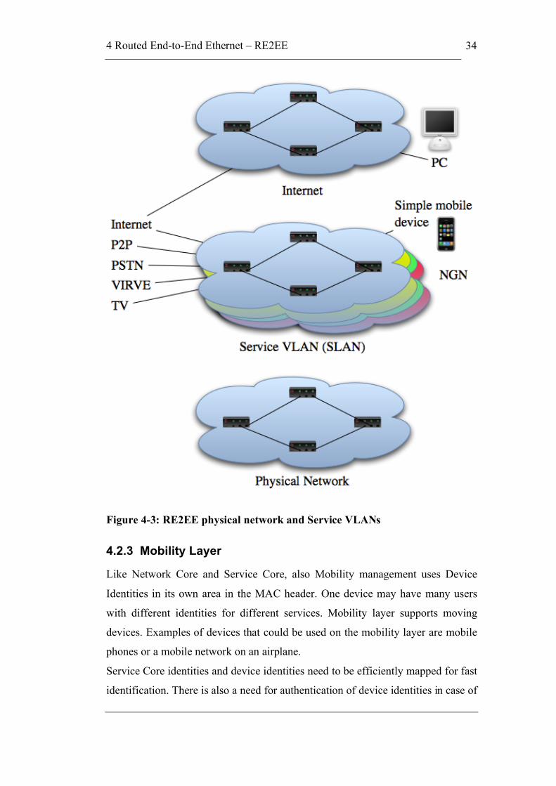
4 Routed End-to-End Ethernet – RE2EE
34
Figure 4-3: RE2EE physical network and Service VLANs
4.2.3 Mobility Layer
Like Network Core and Service Core, also Mobility management uses Device
Identities in its own area in the MAC header. One device may have many users
with different identities for different services. Mobility layer supports moving
devices. Examples of devices that could be used on the mobility layer are mobile
phones or a mobile network on an airplane.
Service Core identities and device identities need to be efficiently mapped for fast
identification. There is also a need for authentication of device identities in case of
4 Routed End-to-End Ethernet – RE2EE
35
mobile hosts. Adding authentication support to the address resolution service
could solve this. This scheme can replace the GPRS tunnelling based mobility
management and Mobile-IP (both v4 and v6). In multi-radio environment, Traffic
Engineering (TE) is needed. [Kan+07]
4.3 Addressing and User Identity in RE2EE
Addressing in RE2EE-networks is based on user identities, terminal MAC address
and routing address. Identities can vary depending on the used namespace.
Namespaces that can be used for example are E.164, IPv4, IPv6, SIP URI, HIP or
NSAP. This means that a potential new service like packet telephony does not
need to use IP at all. It is important to maintain the mappings from Names to
Identities at all layers. Terminal MAC address was introduced in section 2.4.
Routing address is the relay address of the terminal MAC address. It should be
based on the NSAP address format for performance and scalability reasons. The
NSAP address format used in RE2EE will follow the following rule 1) Authority
and Format Identifier (AFI), 2) Data Country Code (DCC), 3) Provider code, 4)
Area code and 5) PE MAC.
Figure 4-4: PE addressing
The NSAP address would identify the PE node to the core network, but towards
the host it would be identified with its normal MAC address. This can be seen in
Figure 4-4. Actually the lowest transmission layer also on the Provider network
can use normal MAC addresses, but the node would be always identified by its
NSAP address. Also all the forwarding entries in the forwarding table would be in
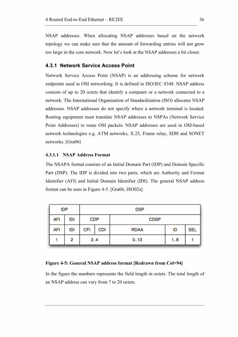
4 Routed End-to-End Ethernet – RE2EE
36
NSAP addresses. When allocating NSAP addresses based on the network
topology we can make sure that the amount of forwarding entries will not grow
too large in the core network. Now let’s look at the NSAP addresses a bit closer.
4.3.1 Network Service Access Point
Network Service Access Point (NSAP) is an addressing scheme for network
endpoints used in OSI networking. It is defined in ISO/IEC 8348. NSAP address
consists of up to 20 octets that identify a computer or a network connected to a
network. The International Organization of Standardization (ISO) allocates NSAP
addresses. NSAP addresses do not specify where a network terminal is located.
Routing equipment must translate NSAP addresses to NSPAs (Network Service
Point Addresses) to route OSI packets. NSAP addresses are used in OSI-based
network technologies e.g. ATM networks, X.25, Frame relay, SDH and SONET
networks. [Gra06]
4.3.1.1 NSAP Address Format
The NSAPA format consists of an Initial Domain Part (IDP) and Domain Specific
Part (DSP). The IDP is divided into two parts, which are Authority and Format
Identifier (AFI) and Initial Domain Identifier (IDI). The general NSAP address
format can be seen in Figure 4-5. [Gra06, ISO02a]
Figure 4-5: General NSAP address format [Redrawn from Col+94]
In the figure the numbers represents the field length in octets. The total length of
an NSAP address can vary from 7 to 20 octets.

4 Routed End-to-End Ethernet – RE2EE
37
4.3.1.2 Initial Domain Part – IDP
IDP is a network addressing domain identifier. It specifies a subdomain of the
global network addressing domain, and identifies the network addressing
authority responsible for assigning NSAP addresses in the specified subdomain.
The initial domain part of the NSAP address itself consists of two parts. The first
part is the authority and format identifier (AFI). The second part is the initial
domain identifier (IDI). This is illustrated in Figure 4-5. [ISO02a]
4.3.1.3 AFI and IDI
The authority and format identifier specifies the format of the IDI, the network
addressing authority responsible for allocating values of the IDI, whether or not
leading zero digits in the IDI are significant and the abstract syntax of the DSP
[ISO02a]. The AFI is defined to be a binary octet (two-decimal digit), and the IDI
is defined to be a four decimal digit number encoded in two octets using Binary
Coded Decimal format. Each nibble of the IDI is used to represent a decimal digit,
using binary value '0000' through '1001'. If AFI has a value of 38, it means that
DSP is in decimal abstract syntax, and 39 means that it is in binary abstract
syntax. IDI can be used to determine the country code as defined in ISO 3166.
More about ISO 3166 can be found from ISO 3166 Maintenance Agency’s
website (http://www.iso.org/iso/country_codes) [Gra06]
The initial domain identifier specifies the network addressing domain from which
values of the DSP are allocated and the network addressing authority responsible
for allocating values of the DSP from that domain. So network addressing
authority identified by the IDI determines the semantics of the DSP. [ISO02a]
4.3.1.4 DSP
The Domain Specific Part (DSP) is the corresponding subdomain address. The
authority identified by the IDP can define a further substructure of the DSP.
[ISO02a]
In the general format of NSAP address, the DSP is divided into Country Domain
Part (CDP) and Country Domain Specific Part (CDSP). CDP is still divided into
Country Format Identifier (CFI) and Country Domain Identifier (CDI). CDSP
consists of Routing Domain and Area Address (RDAA), System Identifier (ID)

4 Routed End-to-End Ethernet – RE2EE
38
and NSAP Selector (SEL). Lengths of these fields can be seen in Figure 4-5 in
octets. [Col+94]
4.3.1.5 NSAP in RE2EE
As mentioned earlier the construction rules for the RE2EE NSAP address format
were AFI, DCC, Provider code, Area code and PE MAC. Length of the Provider
code and Area code has not been decided yet. AFI will be 1 octet, DCC 2 octets
and PE MAC 6 octets. This means that there are in total 11 octets left for Provider
and Area codes. However, it would be nice to be able to carry NSAP addresses in
DA and SA fields in Ethernet frames. To achieve this, we would need to define a
format that fits into 64 bits i.e. has exactly 8 octets altogether. Considering that we
only need these addresses for network provider edge and provider nodes, there is
ample room for all the node addresses that will ever be needed.
Here is an example of how the NSAP address in general is formed in Finland. In
Table 4.1 you can see the values and lengths of the ISO DCC standard NSAP
address fields in Finland.
Table 4.1: ISO DCC standard NSAP address in Finland
Field name Value (hexadecimal) Length (octets)
AFI 39 1
IDI 246F 2
VERSION 00 1
ADMIN_AUTHORITY - 3
LOCAL_PART - 10 (max)
So the address looks like 39.246F.00.xxxxxx.xxxxxxxxxxxxxxxxxxxx. As you
can see from the address format, it has hierarchy built in it for routing purposes.
Every country has their own value in the IDI field. The list is published by ISO
and it is part of the ISO 3166 standard. The official name of the ISO 3166-1
4 Routed End-to-End Ethernet – RE2EE
39
standard is Codes for the representation of names of countries and their
subdivisions – Part 1: Country codes.
This information was partly found from The Finnish Standards Association SFS
website (http://www.sfs.fi/palvelut/tunnukset/).
4.4 Routing in RE2EE
As we are adding hierarchy to the Ethernet network, it makes it possible to also
develop efficient routing. Core routing tables are created using dynamic routing
protocols. These protocols were introduced briefly in section 3.4.1. Usage of
dynamic routing protocols means that every PE node can reach every other PE
node provided it knows its address.
IS-IS routing protocol could be used as the base, as there is a draft of using IS-IS
for routing on Ethernet level. IS-IS is a link state protocol and an Interior Gateway
Protocol (IGP), which means that it is used inside one autonomous system. IS-IS
is not dependent on IP, but rather sits on top of the network layer (in IP terms). To
achieve full end-to-end capability in the RE2EE network we need also an Exterior
Gateway Protocol (EGP). EGP is needed for routing between networks or
administrative domains.
IS-IS routing needs to be modified for the RE2EE by adding new extended TLVs
(Type, Length, Value). TLVs are optional information elements that can be added
inside of a protocol. Type and Length fields are fixed in size, but Value field is of
variable size. Each device is represented as one NET based on the internal MAC
address. Provider network is treated as one IS-IS area with full knowledge of
connected provider devices. [Kan+07]
4.4.1 Routing Example
When host A wants to communicate with host B, A must resolve B’s name to
identities and MAC addresses by sending a control message to one of its PE
nodes, the PE node forwards the query to an address resolution service. From the
response, the PE node picks address info to its cache creating a new cache entry if
the target PE is not yet present in the cache while the PE node returns most of the
response to host A.
4 Routed End-to-End Ethernet – RE2EE
40
When a packet arrives at the outbound PE, based on a cache entry created earlier,
the NSAP address of inbound PE is appended into a new MAC header. This
Inbound NSAP PE address is used for global routing. Reverse route info is cached
automatically at inbound PE node. For routing from inbound PE to host B,
address info that was learned from address resolution will be used.
NSAP address is cached in the outbound PE but not returned to requester. The
cached entry dies if no communication occurs for a period of time. RE2EE
protocol stack in hosts and the PE cache state are synchronised (Host knows for
how long it can stop without a need to resolve a targets name again).
Switches in RE networks and in Switched Ethernets on the way process the
different MAC header parts in parallel sending packets towards their destination
using an appropriate outgoing port. [Kan+07]
4.4.2 802.1aq and IS-IS
IEEE 802.1aq also known as Shortest Path Bridging (SBP) provides shortest path
bridging, which uses a different set of shortest path trees on each node. The node
of each VLAN is set as the root of the tree. Rooting the tree on a per-node basis is
required to ensure a shortest path from one node to any other node. The objective
of shortest path bridging is to guarantee loop free forwarding, while using shortest
path routes. IEEE 802.1aq proposes to use IS-IS protocol to update link state
information. [TPA07]
The standard is still under development and the latest draft, version 0.4, was
released on February 19th 2008. Latest information can be found from the IEEE
802.1 website.
4.5 Address Resolution Mechanism
At the moment the technique to associate domain name to its IP address, is
Domain Name System. This system has been developed for the IPv4 and it should
be replaced with something better to fit the RE2EE network. The target should be
an address resolution service that can be updated by mobile hosts as they move
from one network to another.
One option would be to use Distributed Hash Tables (DHTs), which are known to
be efficient in Peer-to-Peer (P2P) networks. DHTs are a class of decentralised

4 Routed End-to-End Ethernet – RE2EE
41
distributed systems that provide a lookup service similar to a hash table. In the
table there is a pair of name and value stored, which can be retrieved by any
participating node. Responsibility for maintaining the mapping from names to
values is distributed among the nodes. This is done so that changes in the network
cause a minimal amount of disruption and allows the network to scale to
extremely large numbers of nodes and to handle continual node arrivals,
departures, and failures.

5 RE2EE – Proof of Concept
42
5 RE2EE – Proof of Concept
In this chapter we will show how the Proof of Concept network was built and
which equipment was used in the network. This chapter also describes all the
functions that the network offers and how they were implemented. Usage
instructions for all the functions are also introduced in this chapter. We used two
basic PCs running Linux operating system for the Proof of Concept
implementation. The next section compares the RE2EE concept to the Proof of
Concept.
5.1 Differences between RE2EE and the Proof of Concept
Implementing all the features from the RE2EE concept was not in the scope of the
thesis and due to that not all of the features exist. Many features that are not part
of this thesis could be done in another thesis to make the RE2EE concept more
complete. More about the future work in the conclusion chapter.
Routing/forwarding tables are created manually, because no routing protocol was
implemented to the Proof of Concept network. This means that no IS-IS protocol
was implemented as an IGP.
NSAP addressing was introduced in the previous chapter, but those addresses are
not used in the Proof of Concept. Normal MAC addresses are used as location
addresses for hosts, PEs and Providers. Use of NSAP addresses would have
required making a lot of modifications to Scapy’s Ethernet protocol and in a
small-scale Proof of Concept network there was no need for bigger address space
with hierarchy.
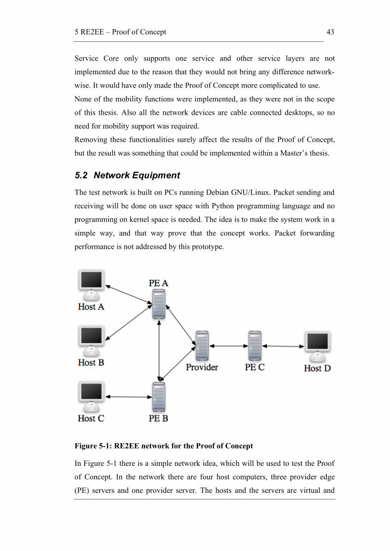
5 RE2EE – Proof of Concept
43
Service Core only supports one service and other service layers are not
implemented due to the reason that they would not bring any difference network-
wise. It would have only made the Proof of Concept more complicated to use.
None of the mobility functions were implemented, as they were not in the scope
of this thesis. Also all the network devices are cable connected desktops, so no
need for mobility support was required.
Removing these functionalities surely affect the results of the Proof of Concept,
but the result was something that could be implemented within a Master’s thesis.
5.2 Network Equipment
The test network is built on PCs running Debian GNU/Linux. Packet sending and
receiving will be done on user space with Python programming language and no
programming on kernel space is needed. The idea is to make the system work in a
simple way, and that way prove that the concept works. Packet forwarding
performance is not addressed by this prototype.
Figure 5-1: RE2EE network for the Proof of Concept
In Figure 5-1 there is a simple network idea, which will be used to test the Proof
of Concept. In the network there are four host computers, three provider edge
(PE) servers and one provider server. The hosts and the servers are virtual and
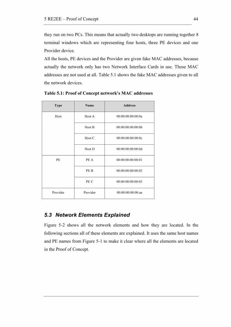
5 RE2EE – Proof of Concept
44
they run on two PCs. This means that actually two desktops are running together 8
terminal windows which are representing four hosts, three PE devices and one
Provider device.
All the hosts, PE devices and the Provider are given fake MAC addresses, because
actually the network only has two Network Interface Cards in use. Those MAC
addresses are not used at all. Table 5.1 shows the fake MAC addresses given to all
the network devices.
Table 5.1: Proof of Concept network's MAC addresses
5.3 Network Elements Explained
Figure 5-2 shows all the network elements and how they are located. In the
following sections all of these elements are explained. It uses the same host names
and PE names from Figure 5-1 to make it clear where all the elements are located
in the Proof of Concept.
Type Name Address
Host A 00:00:00:00:00:0a
Host B 00:00:00:00:00:0b
Host C 00:00:00:00:00:0c
Host
Host D 00:00:00:00:00:0d
PE A 00:00:00:00:00:01
PE B 00:00:00:00:00:02
PE
PE C 00:00:00:00:00:03
Provider Provider 00:00:00:00:00:aa
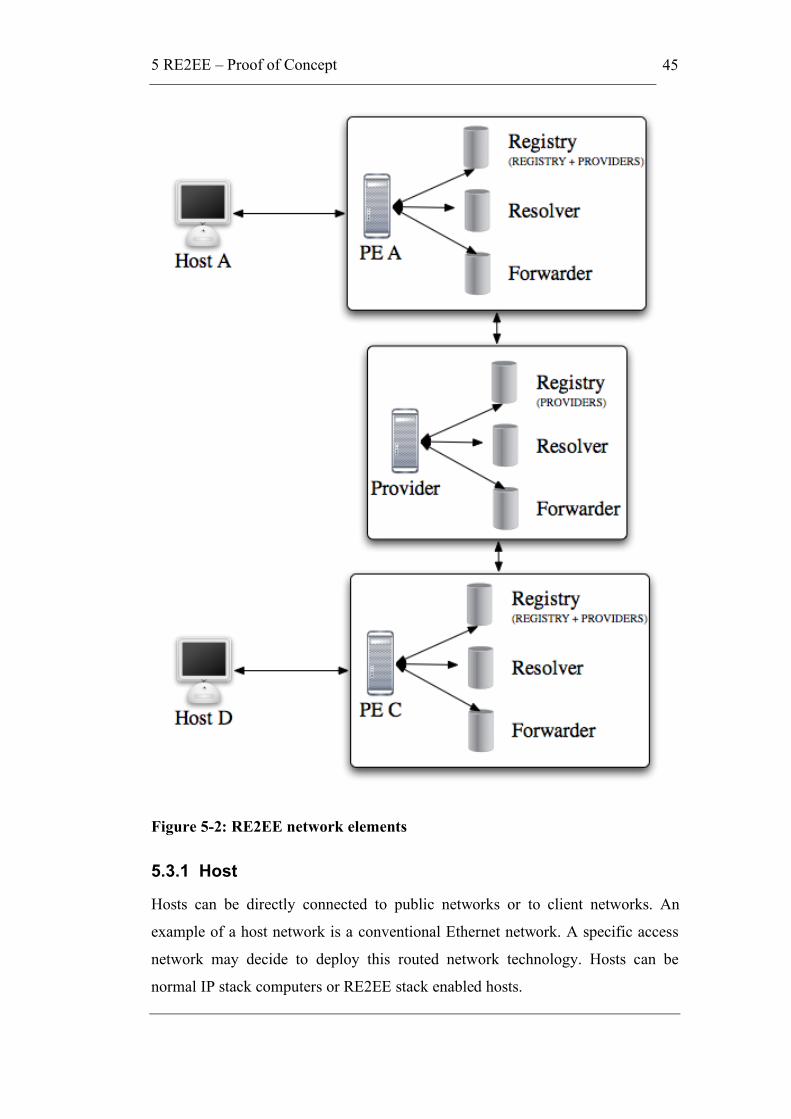
5 RE2EE – Proof of Concept
45
Figure 5-2: RE2EE network elements
5.3.1 Host
Hosts can be directly connected to public networks or to client networks. An
example of a host network is a conventional Ethernet network. A specific access
network may decide to deploy this routed network technology. Hosts can be
normal IP stack computers or RE2EE stack enabled hosts.
5 RE2EE – Proof of Concept
46
Host A needs to register itself to the home PE node (PE A) by sending an Ethernet
packet. In the packet Host A tells its own MAC address and its identity. All hosts
register themselves the same way to their home PE nodes.
5.3.2 Provider Edge – PE
PE nodes exchange information between each other so that they know where to
find all other PE nodes. PE nodes contain a registry of the hosts, which is
explained more thoroughly later. Because the Proof of Concept does not have a
proper network wide address resolution service, the registries in PE nodes will be
copied manually from all PE nodes to all PE nodes.
5.3.3 Provider
Provider nodes are similar to PE nodes, but hosts are not registering themselves to
them. Providers form the core of the network and they forward only those
encapsulated packets to next hop using their registry database. Providers do not
know anything about the hosts. They only have the information about where to
forward the packet to get it to the right PE node.
5.3.4 Registry
Registry is a database located in PE nodes and Provider nodes. The database for
the registry is created with MySQL (http://www.mysql.com/). Hosts will send
information in Ethernet packets to their PE nodes about themselves and PE nodes
will insert their information to the database. This registry works in this Proof of
Concept as routing table. The database is synchronised manually with all the PE
nodes in the network.
5.3.5 Resolver
Resolver for host information is located in the PE nodes. It is needed for finding
the location of the destination hosts when hosts are sending the packets. A
registered host can be found from the REGISTRY table with a proper query. The
needed information can be found with destination host’s identity and MAC
address. Resolver then sends the MAC address information of the PE node of the
destination host to forwarder.
5 RE2EE – Proof of Concept
47
The other resolver is needed for the next node information in forwarding the
packet in the core network. This information is located in PROVIDERS table and
is used the same way as REGISTRY table.
5.3.6 Forwarder
Forwarder is a system block which will forward the packets to next PE node or
Provider node. It exists in PE nodes and Provider nodes. The forwarder gets the
location of the host or the home PE node of the host from resolver and then
forwards the packet to the next node.
5.4 Ethernet Packet Generation with Scapy
Scapy is an interactive packet manipulation program made with Python
programming language. It is able to forge or decode packets of a wide number of
protocols, send them on the wire, capture them, match requests and replies, and
much more. Scapy uses the Python interpreter as a command board. This means
that you can use directly Python language for creating the source code. [Bur+07]
The different between Scapy and most other networking tools is that it allows you
to do nearly anything and not only the things that the author had in mind. It also
does not try to interpret anything; it just decodes the packets for the person to
interpret. The third main difference is that it gives you all the information from
your network and not only the information that the author thought that is needed.
The main idea is that Scapy does not give you any boundaries in the packet
manipulation. You can put any value in any field in any packet, and stack them
like you want.
In this Proof of Concept Ethernet packets will be constructed with Scapy. Scapy is
also used for capturing and analysing the content of the packet payload. More
about Scapy can be found from its official website
http://www.secdev.org/projects/scapy/
5.4.1 Implemented Ethernet Packets
All the packets are generated with Scapy. Hosts are always sending Ethernet
packets, which have EtherType 0x9999. Encapsulated packets have EtherType
0x9998 for the outer packet, but the inside one is using still the 0x9999. The
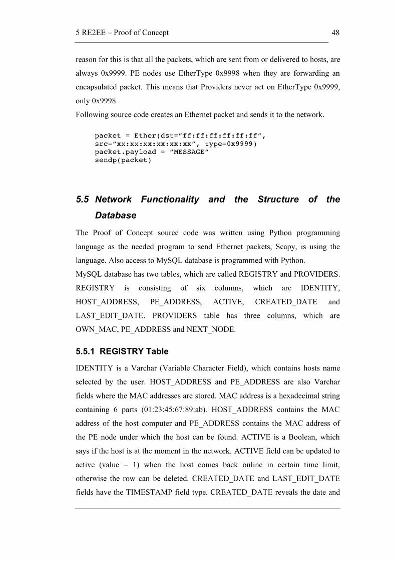
5 RE2EE – Proof of Concept
48
reason for this is that all the packets, which are sent from or delivered to hosts, are
always 0x9999. PE nodes use EtherType 0x9998 when they are forwarding an
encapsulated packet. This means that Providers never act on EtherType 0x9999,
only 0x9998.
Following source code creates an Ethernet packet and sends it to the network.
packet = Ether(dst=”ff:ff:ff:ff:ff:ff”, src=”xx:xx:xx:xx:xx:xx”, type=0x9999) packet.payload = “MESSAGE” sendp(packet)
5.5 Network Functionality and the Structure of the
Database
The Proof of Concept source code was written using Python programming
language as the needed program to send Ethernet packets, Scapy, is using the
language. Also access to MySQL database is programmed with Python.
MySQL database has two tables, which are called REGISTRY and PROVIDERS.
REGISTRY is consisting of six columns, which are IDENTITY,
HOST_ADDRESS, PE_ADDRESS, ACTIVE, CREATED_DATE and
LAST_EDIT_DATE. PROVIDERS table has three columns, which are
OWN_MAC, PE_ADDRESS and NEXT_NODE.
5.5.1 REGISTRY Table
IDENTITY is a Varchar (Variable Character Field), which contains hosts name
selected by the user. HOST_ADDRESS and PE_ADDRESS are also Varchar
fields where the MAC addresses are stored. MAC address is a hexadecimal string
containing 6 parts (01:23:45:67:89:ab). HOST_ADDRESS contains the MAC
address of the host computer and PE_ADDRESS contains the MAC address of
the PE node under which the host can be found. ACTIVE is a Boolean, which
says if the host is at the moment in the network. ACTIVE field can be updated to
active (value = 1) when the host comes back online in certain time limit,
otherwise the row can be deleted. CREATED_DATE and LAST_EDIT_DATE
fields have the TIMESTAMP field type. CREATED_DATE reveals the date and
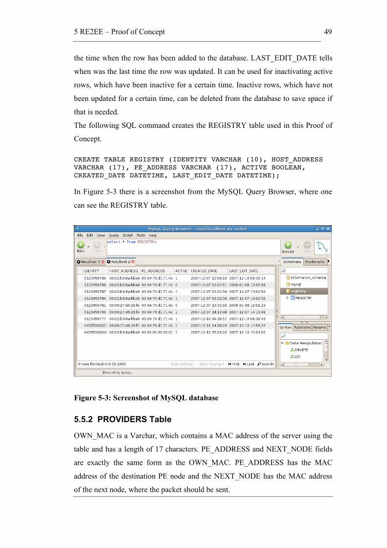
5 RE2EE – Proof of Concept
49
the time when the row has been added to the database. LAST_EDIT_DATE tells
when was the last time the row was updated. It can be used for inactivating active
rows, which have been inactive for a certain time. Inactive rows, which have not
been updated for a certain time, can be deleted from the database to save space if
that is needed.
The following SQL command creates the REGISTRY table used in this Proof of
Concept.
CREATE TABLE REGISTRY (IDENTITY VARCHAR (10), HOST_ADDRESS VARCHAR (17), PE_ADDRESS VARCHAR (17), ACTIVE BOOLEAN, CREATED_DATE DATETIME, LAST_EDIT_DATE DATETIME);
In Figure 5-3 there is a screenshot from the MySQL Query Browser, where one
can see the REGISTRY table.
Figure 5-3: Screenshot of MySQL database
5.5.2 PROVIDERS Table
OWN_MAC is a Varchar, which contains a MAC address of the server using the
table and has a length of 17 characters. PE_ADDRESS and NEXT_NODE fields
are exactly the same form as the OWN_MAC. PE_ADDRESS has the MAC
address of the destination PE node and the NEXT_NODE has the MAC address
of the next node, where the packet should be sent.

5 RE2EE – Proof of Concept
50
The following SQL command creates the PROVIDERS table used in this Proof of
Concept.
CREATE TABLE PROVIDERS (OWN_MAC VARCHAR (17), PE_ADDRESS VARCHAR (17), NEXT_NODE VARCHAR (17));
Note that we use such a long format for MAC addresses for simplicity of Python
programming.
5.5.3 Home PE Discovery by a Host
Host sends a broadcast message to the network with its MAC address and the
needed service from the network. Figure 5-4 shows the messages between host
and the PE. Service can be anything like basic Internet service, PSTN service or
TV service. All the PE nodes that get the discovery message reply to the host by
sending their MAC address and service provider identifier. The fastest one with
the reply will be selected as the home PE node. In this Proof of Concept services
are not implemented.
Figure 5-4: Home PE discovery by a host
5.5.4 Host Registering to PE
Host sends an Ethernet packet to the PE node’s address it got in the discovery in
the last section. Ethernet packet has the basic information about the host. Mainly
host’s MAC address, identity and that it wants to register itself with the certain
service. Registration procedure is shown in Figure 5-5.

5 RE2EE – Proof of Concept
51
Figure 5-5: Host registering to PE
Registering adds a row to the REGISTRY table or in case the MAC address can
be found from the table, the column ACTIVE is only updated to 1 and
LAST_EDIT_DATE is updated.
The following SQL command inserts a new host to the table used in this Proof of
Concept.
INSERT INTO REGISTRY (IDENTITY, HOST_ADDRESS, PE_ADDRESS, ACTIVE, CREATED_DATE, LAST_EDIT_DATE) values(‘xxxxxxxxxx’, ‘xx:xx:xx:xx:xx:xx’, ‘xx:xx:xx:xx:xx:xx’, 1, SYSDATE(), SYSDATE());
The following SQL command updates an inactive host to active and at the same
time updates also the MAC address of the host and the PE node.
UPDATE REGISTRY set ACTIVE=1, LAST_EDIT_DATE=SYSDATE(), HOST_ADDRESS=‘xx:xx:xx:xx:xx:xx’, PE_ADDRESS=‘xx:xx:xx:xx:xx:xx’ where IDENTITY=‘xxxxxxxxxx’;
The following SQL command updates the MAC address of the host and the PE
node for a certain identity.
UPDATE REGISTRY set HOST_ADDRESS=’xx:xx:xx:xx:xx:xx’, LAST_EDIT_DATE=SYSDATE(), PE_ADDRESS=’xx:xx:xx:xx:xx:xx’ where IDENTITY=‘xxxxxxxxxx’;
Figure 5-6 shows how it looks in the Terminal screen when host is finding a home
PE node and registering to it. The used commands are find_PE() and
register(“identity”).
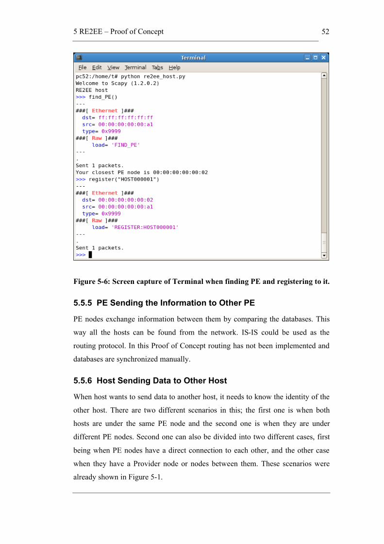
5 RE2EE – Proof of Concept
52
Figure 5-6: Screen capture of Terminal when finding PE and registering to it.
5.5.5 PE Sending the Information to Other PE
PE nodes exchange information between them by comparing the databases. This
way all the hosts can be found from the network. IS-IS could be used as the
routing protocol. In this Proof of Concept routing has not been implemented and
databases are synchronized manually.
5.5.6 Host Sending Data to Other Host
When host wants to send data to another host, it needs to know the identity of the
other host. There are two different scenarios in this; the first one is when both
hosts are under the same PE node and the second one is when they are under
different PE nodes. Second one can also be divided into two different cases, first
being when PE nodes have a direct connection to each other, and the other case
when they have a Provider node or nodes between them. These scenarios were
already shown in Figure 5-1.
5 RE2EE – Proof of Concept
53
5.5.6.1 Hosts Under the Same PE Node
Host A sends a packet to its home PE (PE A) with a message and the identity of
host B. PE A checks the home PE for the host B from its REGISTRY table. Host
B is found under the same PE node, so the packet can be delivered directly to host
B. In the packet source MAC address is changed from host A’s address to PE A’s
address and the destination MAC address from PE A’s address to host B’s
address. PE A also adds host A’s identity to the payload. This is shown in Figure
5-7.
Figure 5-7: Host A sending a message to Host B under the same PE node.
Host A never sees the MAC address of the Host B and vice versa. The reason for
this is that the hosts are not allowed to see anything from the networks. They just
know the identity of the host they want to connect. Host B can reply to host A
with the identity that it got in the payload with the message.
The main difference to layer 2 switching is that it is possible to connect many
corporate networks to one PE node without them being able to see the other
networks and the devices under it.
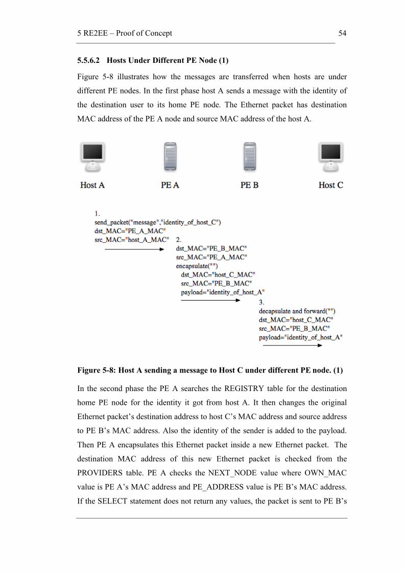
5 RE2EE – Proof of Concept
54
5.5.6.2 Hosts Under Different PE Node (1)
Figure 5-8 illustrates how the messages are transferred when hosts are under
different PE nodes. In the first phase host A sends a message with the identity of
the destination user to its home PE node. The Ethernet packet has destination
MAC address of the PE A node and source MAC address of the host A.
Figure 5-8: Host A sending a message to Host C under different PE node. (1)
In the second phase the PE A searches the REGISTRY table for the destination
home PE node for the identity it got from host A. It then changes the original
Ethernet packet’s destination address to host C’s MAC address and source address
to PE B’s MAC address. Also the identity of the sender is added to the payload.
Then PE A encapsulates this Ethernet packet inside a new Ethernet packet. The
destination MAC address of this new Ethernet packet is checked from the
PROVIDERS table. PE A checks the NEXT_NODE value where OWN_MAC
value is PE A’s MAC address and PE_ADDRESS value is PE B’s MAC address.
If the SELECT statement does not return any values, the packet is sent to PE B’s

5 RE2EE – Proof of Concept
55
MAC address. It means that the PE B has a direct connection to PE A. In this case
this new Ethernet packet is sent to PE B with destination MAC address of PE B
and source MAC address of PE A.
In the third phase PE B checks if the inner packet’s source is the same as the
destination of the outer packet, because this means that the packet can be
processed as it has arrived to the home PE node of the destination. PE B
decapsulates the outer Ethernet packet away and forwards the inner one to the
right destination, which is host C.
There is no risk of masquerading because the hosts are registered to the PE nodes
with their identities and this identity is carried in the encapsulated packet to the
destination host. With this identity the destination host can send a reply to the
sender.
5.5.6.3 Hosts Under Different PE Node (2)
Figure 5-9 shows how the network works when there is no direct connection
between the PE nodes. In the core network the Provider routers are forwarding the
packets to correct PE node.
This case is quite similar to the previous one, but the main difference is that the
Provider or Providers forward the Ethernet packet in the Core Network. Providers
are not encapsulating nor decapsulating the packets while they are transferred.
Decapsulation always happens in the destination’s home PE node.
In the Core network the Providers check from the PROVIDERS table the next
node to forward the packet closer to the destination PE node. When the packet
arrives to destination PE node, it decapsulates the packet and sends the inner
Ethernet packet to the destination host.
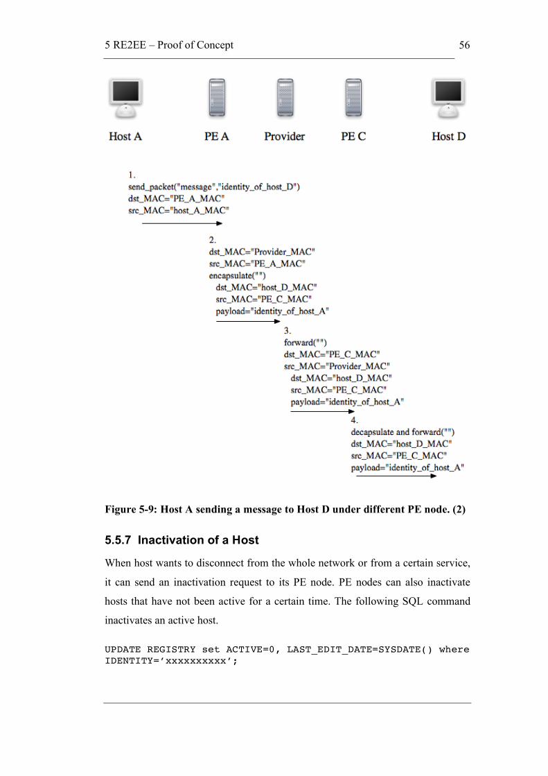
5 RE2EE – Proof of Concept
56
Figure 5-9: Host A sending a message to Host D under different PE node. (2)
5.5.7 Inactivation of a Host
When host wants to disconnect from the whole network or from a certain service,
it can send an inactivation request to its PE node. PE nodes can also inactivate
hosts that have not been active for a certain time. The following SQL command
inactivates an active host.
UPDATE REGISTRY set ACTIVE=0, LAST_EDIT_DATE=SYSDATE() where IDENTITY=’xxxxxxxxxx’;

5 RE2EE – Proof of Concept
57
The automatic inactivation after a certain time window can be done using the
LAST_EDIT_DATE field in the REGISTY table. This functionality has not been
implemented to the PE devices in the Proof of Concept.
5.6 Usage of the Proof of Concept Network
This section will explain the usage of the Proof of Concept network. It will cover
all the implemented commands that a host can process. The processes that a host
can do are the following: discovering a home PE node, registration to a PE node,
inactivate itself from the PE node, sending a message to any host and receiving a
message from any host.
5.6.1 Home PE Node Discovery and Registration to It
The first task that a host needs to do is to find a home PE node. This is done with
find_PE() command. PE nodes will answer to the discovery with their MAC
address. Host will select the closest one.
Registration to the home PE node is done using command
register(“IDENTITY_OF_THE_HOST”). Identity of the host needs to be exactly
10 characters. If the PE node accepts the registration of the host, it will reply with
accepted registration. Registration also needs to be done when the user has
changed the location in the network, the MAC address of the host has changed or
the host has not been active for a certain time.
5.6.2 Inactivation of the Host
Host can inactivate itself by executing command
inactivate(“IDENTITY_OF_THE_HOST”). This will update the database on the
PE node and no messages will be transferred to this identity anymore. New
registration will active the identity again.
5.6.3 Sending Packets
Registered hosts can send packets to any registered host if they know the identity
of the other host. They don’t need to know the location of the destination host,
because the network handles that. Actually it is part of the security that hosts only
know their home PE node. Executing command

5 RE2EE – Proof of Concept
58
send_packet(“MESSAGE”,”IDENTITY_OF_THE_DESTINATION_HOST”) will
send the message to the destination host’s screen.
5.6.4 Receiving Packets
To be able to receive messages in this Proof of Concept, hosts need to be in the
receiving mode. This is done by executing the receive_packets() command. To
exit the receiving mode host needs to press CTRL+C.

6 Analysis of Results
59
6 Analysis of Results
In this chapter we will compare address space, routing, scalability and other
features of RE2EE to IPv4, IPv4 with NAT, IPv6 and basic Ethernet. These
features are linked together tightly with hierarchy and this will be analysed with
informative graphs. The results of the Proof of Concept are analysed as well.
These results are compared to the RE2EE concept. In the end of this chapter we
explain all the problems, which were encountered while creating the Proof of
Concept network.
6.1 Address Space
As we have been talking about the address space problem in IPv4, it is good to
actually compare the address space differences between all these technologies.
Figure 6-1 depicts a chart, which shows the address spaces of all the technologies
that are covered in this thesis. On the x-axis there are different technologies and
on the logarithmic y-axis there is the address space size. The red line shows the
estimated address space size that is needed globally.
The main problem with IPv4 is that not all of the addresses can be easily used, as
covered in section 3.1. The reason why IPv4 added with Network Address
Translation has larger address space in the graph is because it allows many
computers to connect to the Internet with just one public IP address. One still has
to remember that NAT does not actually enlarge the real address space. Internet
Protocol’s idea has been that all things should be addressable and that this forms
the freedom for creating new service. NAT did not support this idea.

6 Analysis of Results
60
Figure 6-1: Address space comparison
When looking at the Figure 6-1 it seems like EUI-48 address space will also be
soon too small if the amount of connected devices in Internet gets a lot higher, but
actually this is not expected to happen in the next 100 years. In RE2EE the EUI-
64 should be used or at least it should be taken into account in the development of
the address hierarchy, as this address space is not expected to run out in the
foreseeable future. We also note, that in the RE2EE concept forwarding is
recursive and networks behind one level of PE devices can use overlapping
addresses if there is a global name space and a resolution service that can resolve
globally unique host or user names to a string of addresses. Each string will
identify uniquely at least one destination PE device that is capable of reaching the
destination node itself.
Extending RE2EE addressing to 128 bits and making it as scalable as IPv6
addressing could for example be achieved by allocating device MAC addresses
dynamically and having a 2 layer hierarchy in the network. In such a schema,
global addressing would be based the pair of dynamic MAC address and the
NSAP address. It seems that in the near future this will not be needed.
6 Analysis of Results
61
It is also important to create the address space efficiently usable and not like in
IPv4 where the big classes are wasting a great amount of IP addresses. This can
be done by well-constructed NSAP addresses.
6.2 Routing
The whole way through this thesis we have been talking about hierarchy and
scalability linked with routing. If the technology is supposed to scale to the global
network, it needs efficient routing to work properly. Routing needs hierarchy in
the addresses to be efficient and this leads to the conclusion that worldwide
networks demand hierarchy. All of these discussed technologies have hierarchy in
their addresses except Ethernet. Basic Ethernet network uses Spanning Tree
Protocol for routing, but it does not scale for global networks. This was covered
more thoroughly in section 2.9.
Adding hierarchy with the NSAP addresses to Ethernet networks would allow
Ethernet networks to scale globally. The reason for using only Ethernet in the
end-to-end principle is because this facilitates recursion in the network structure,
addressing and routing. Ethernet is also the most common and one of the cheapest
technologies to build networks today.
6.3 Scalability of the RE2EE
Let us assume that one core Routed Ethernet Provider Edge (RE-PE) device can
serve a minimum of 50 000 users. This means that less than 200 000 devices are
needed to serve 10 billion users. In Table 6.1 there are calculations about the
amount of devices needed with different amount of network users and RE-PE
device serving power. At the moment, there are about 1 billion Internet users all
around the world and to serve them we would need less than 20 000 RE-PE
devices. In core routing all these devices need to know about each other, which
requires well-designed addresses for hierarchy and efficient routing protocols.

6 Analysis of Results
62
Table 6.1: Sanity check of RE2EE
Users in the network User amount one RE-PE can serve Amount of devices needed
1 000 000 000 10 000 100 000
1 000 000 000 50 000 20 000
10 000 000 000 10 000 1 000 000
10 000 000 000 50 000 200 000
Let us assume that a backbone supports link capacities of 1 Tbit/s. Subscribers
need to have a 100 Mbit/s dedicated connection for high quality video like
HDTV. This means that one backbone link can serve 10 000 subscribers at the
same time. When we take into account that all the subscribers are not using the
full capacity at the same time, we can estimate that the backbone can easily serve
more than 100 000 subscribers. Actually at the moment Internet Service Providers
calculate the usage per subscriber even lower, which would mean that one link
could serve even up to 500 000 subscribers. Current Core IP routers scale to less
than 1 million entries in their routing tables. If an operator has less than 50 000
users, it can become an access ISP but will not be seen on the core.
If we would use NSAP addresses aligned with the topology of the network, we
would need most probably less than 30 000 entries in the Core Routing table.
Today there are 22 000 Autonomous System (AS) numbers allocated to operators
and the number is rather declining than increasing. The reason for this assumption
comes from the expectation that the number of ISPs is going down. At the
moment bigger ISPs are buying smaller ones and also small ISPs are merging.
[Kan+07]
On the other hand, in an article in The Internet Protocol Journal, Geoff Huston
said that the number of Autonomous Systems has been increasing since 2002
[Hus06]. He predicts that the 16-bit AS number pool will be exhausted in March
16th 2011. But actually this does not matter anymore as Internet Assigned
Numbers Authority (IANA) extended the AS Number field to 32 bits in size in
6 Analysis of Results
63
November 2006 [Hus08]. RFC 4893 shows a way of supporting four-octet AS
number space in BGP.
Today AS numbers are assigned to both corporate networks and ISPs. The main
reason for the growth of the AS numbers has been the multihoming support,
which is needed in corporate networks. Proper use of multihoming in IPv4
networks requires that the company acquire an AS-number. Multihoming
increases the reliability of the Internet connection for an IP network by allowing
the network to be connected to two different ISPs. The problem that this causes is
again, that it enlarges the core routing tables. In RE2EE solution one important
design objective is that multihoming does not enlarge the RE core routing tables.
6.4 Security
Basic Ethernet and IPv4 do not provide proper security in the network and due to
that there have been other security protocols implemented over them. IPv6 is a
newer protocol and security was taken into account in the development. One of
the main updates in IPv6 is the mandatory inclusion of IP Security (IPsec) in the
protocol, which makes it fundamentally more secure than the older IPv4 standard.
RE2EE will bring more security by separating operator networks from customer
networks. Then operators can decide if they trust other operators or will they be
hidden from others. All the trust agreements can be formulated individually
between every directly connected operator. This kind of follows the trust-to-trust
principle by Dave Clark, which was covered in section 3.1.4.8.
The other security feature comes from different services, which allow users to
have different identities in different services. This means that they can surf the
Internet anonymously, receive calls and e-mails only from users whose identity
has been assured by a trusted party such as an operator. Also these service layers
are invisible to others, so the data traffic is not available to the other layers.
6.5 Results from the Proof of Concept
The goal of the Proof of Concept network was to build a network, which uses
only MAC addresses over Ethernet for communication purposes. IP addresses
were not allowed to be used for sending messages to other hosts. This meant that
Ethernet packets had to carry all the information in their headers and payload for
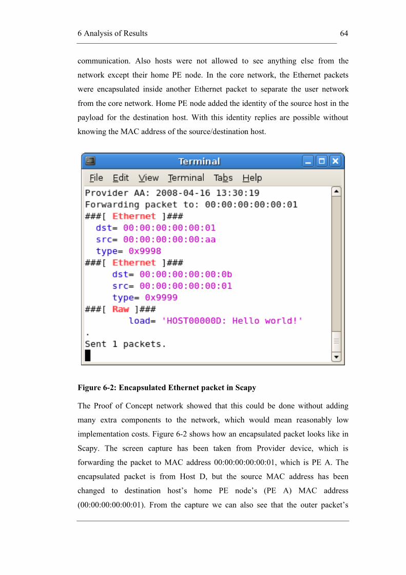
6 Analysis of Results
64
communication. Also hosts were not allowed to see anything else from the
network except their home PE node. In the core network, the Ethernet packets
were encapsulated inside another Ethernet packet to separate the user network
from the core network. Home PE node added the identity of the source host in the
payload for the destination host. With this identity replies are possible without
knowing the MAC address of the source/destination host.
Figure 6-2: Encapsulated Ethernet packet in Scapy
The Proof of Concept network showed that this could be done without adding
many extra components to the network, which would mean reasonably low
implementation costs. Figure 6-2 shows how an encapsulated packet looks like in
Scapy. The screen capture has been taken from Provider device, which is
forwarding the packet to MAC address 00:00:00:00:00:01, which is PE A. The
encapsulated packet is from Host D, but the source MAC address has been
changed to destination host’s home PE node’s (PE A) MAC address
(00:00:00:00:00:01). From the capture we can also see that the outer packet’s

6 Analysis of Results
65
EtherType is 0x9998 and the encapsulated packet has EtherType 0x9999.
Encapsulated Ethernet packet’s payload contains the identity of the sender with its
message.
The main features for the hosts required in the PoC were discovery of PE nodes,
registering to a PE node, sending a message to a host and receiving a message
from a host. These were all successfully implemented to the network and all these
features can be executed using the syntax given in section 5.6. PE nodes main
tasks in the PoC were to reply to hosts’ discovery messages, to accept
registrations from hosts and to forward the packets. All the network devices,
which were PE nodes and Provider node, on the other hand required to be able to
forward messages based on the forwarding tables in the MySQL database,
encapsulate the Ethernet packets in cases where the core network was needed for
the delivery of the message. These network features were also successfully
implemented.
Routing speeds could not be tested, because the PoC did not have routing
implemented, so only forwarding was used for packet delivery. Also other speed
tests were found needless because the whole network was virtual and the two
computers running the Linux operating system were quite slow. Actually one
problem occurred due to the slow computers and maybe also due to Python
language being not so fast. This is discussed later in section 6.6.3.
6.6 Problems Encountered in the Proof of Concept
This section covers all the bigger problems encountered when building the Proof
of Concept network.
6.6.1 Network Interface Cards
In the computers there are different network interface cards and they have
behaved differently in some situations. When the identity was checked with
Python’s string method find(), one computer always returned one character less
than the other. This was the reason for fixing the identity to exactly 10 characters.

6 Analysis of Results
66
6.6.2 Ethernet Packet Inside an Ethernet Packet
When an Ethernet packet is encapsulated inside another Ethernet packet with
Scapy on the PE server before sending it to the destination PE server everything
works fine. The problem was in capturing the packet in the destination PE. Outer
Ethernet packet looks fine, but the inner packet in the payload is in unreadable
format. This was solved by testing different methods that Scapy offers for
capturing data. The solution was to create immediately a whole packet variable
out of the inner packet and from this packet you could print the payload.
6.6.3 Replies Need to Be Delayed
Host sends a message to find a home PE or any other message where it needs to
get a response from the server. If there is no delay in the server side response, the
host computer is too slow in starting the sniffing of the response. 0.3-second delay
in sending the response fixed the problem. This delay size was found by testing
different values a few times. In faster computers this might not be needed at all.
7 Conclusions
67
7 Conclusions
The goal of this thesis was to investigate and analyse Ethernet and IEEE 802.1
standards, and IPv4 and IPv6 protocols. From these combine a new idea of
Routed End-to-End Ethernet in theory and build a Proof of Concept network that
works in a small scale. The concepts idea is to get rid of the IP addresses and only
use MAC addresses for host identification and routing Ethernet packets in the
network.
From the analysis we found the following conclusion for Internet Protocols
success; the main reason for IPv4 to spread so effectively was the simple routing
with its hierarchy in the addresses, which made it scale so well. Now the amount
of Internet users has expanded too much for IPv4 to handle them. Routing tables
are becoming oversized and address space is getting exhausted. There are no more
tricks to postpone the change of the main addressing for Internet. IPv6 has been
ready to be used for quite a long time, but still Internet users have not changed
from IPv4 to IPv6. Some operators have started to update their networks to
support IPv6 and they are also offering IPv6 for customers. Still it has not been a
success like IPv4 was. The ratio of IPv6 traffic volume to IPv4 traffic volume has
been less than 0,1%. [IAJ07]
The development of this Routed End-to-End Ethernet started from these
problems. Using the MAC addresses already used in normal Ethernet networks
was a good starting point, because the address space given with EUI-48 is already
big enough. It can be easily enlarged with EUI-64, which already supports up to
1.8 *1019 addresses. With recursion and network hierarchy this can be further
extended. The usage of only Ethernet would also get rid of the address translation
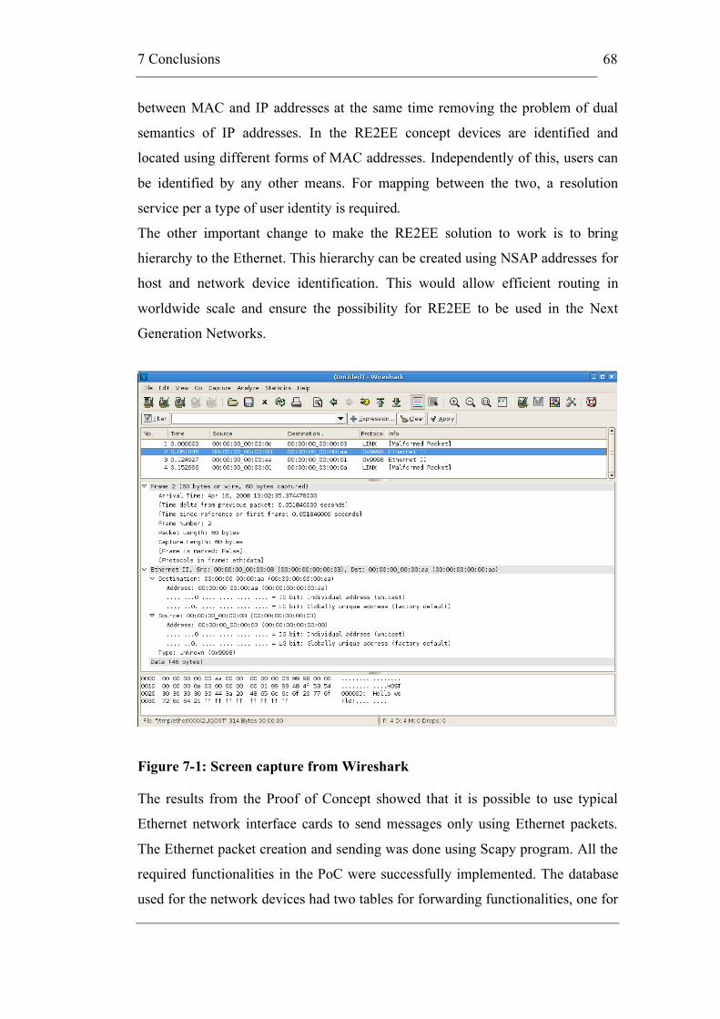
7 Conclusions
68
between MAC and IP addresses at the same time removing the problem of dual
semantics of IP addresses. In the RE2EE concept devices are identified and
located using different forms of MAC addresses. Independently of this, users can
be identified by any other means. For mapping between the two, a resolution
service per a type of user identity is required.
The other important change to make the RE2EE solution to work is to bring
hierarchy to the Ethernet. This hierarchy can be created using NSAP addresses for
host and network device identification. This would allow efficient routing in
worldwide scale and ensure the possibility for RE2EE to be used in the Next
Generation Networks.
Figure 7-1: Screen capture from Wireshark
The results from the Proof of Concept showed that it is possible to use typical
Ethernet network interface cards to send messages only using Ethernet packets.
The Ethernet packet creation and sending was done using Scapy program. All the
required functionalities in the PoC were successfully implemented. The database
used for the network devices had two tables for forwarding functionalities, one for

7 Conclusions
69
home PE nodes use and one for Providers to use in the core network. Before
entering the core network, the packets were encapsulated inside another Ethernet
packet for security reasons. This was also implemented successfully in the PoC.
In Figure 7-1 there is a screen capture from Wireshark program, which is a
network protocol analyser. It shows the packets sent in the PoC network when
Host D sends a message to Host A.
The first packet is from Host D to its home PE node (PE C). PE C encapsulated
this packet inside another Ethernet packet and forwards it to next hop, which is
Provider. Provider forwards it to PE A, which notices that it has the destination
host registered to it. Packet is decapsulated and sent to Host A. One can also see
all the used header fields with the appropriate information.
7.1 Future Research
In this part of the chapter we will talk about the future work that came up while
writing this thesis. They are not in any particular order, but all are needed to be
done before a proper RE2EE network can be built.
7.1.1 RE2EE and IP Networks
There is a need to make RE2EE network to work with IP networks. This is really
important for the spreading and success of the RE2EE.
7.1.2 Addressing
The addressing for the RE2EE should be based on NSAP. This means that an
exact form of the NSAP address is needed. The scalability of the network will be
guaranteed if the addressing has proper hierarchy, which enables efficient routing.
7.1.3 Routing
The routing algorithms for IGP and EGP need to be selected and implemented. At
least IS-IS should be checked carefully.
7.1.4 Service Discovery
Different services need to be implemented by adding the service layers.
Registrations need to be based on a service.

7 Conclusions
70
7.1.5 Mobility Management
Mobile hosts also need to be handled by the network. This means at least fast re-
registration of a host when the location has been changed.
7.1.6 Other
If RE2EE is used to create large networks, things like QoS, service provisioning,
performance monitoring, network management etc will be needed. Ideally, quite a
rich set of protocols would be nice to run directly on top of Ethernet.
References
71
References
[Abu+06] Abuguba S. Moldován I. Verification of RSTP convergence and
scalability by measurements and simulations, May 2006,
http://miau.gau.hu/miau/94/rstp.pdf, Retrieved on 18.4.2008.
[APN08] APNIC’s BGP Routing Table Analysis - DIX-IE Data,
http://thyme.apnic.net/current/data-summary, Retrieved on
16.4.2008.
[Aud+07] Audet F. Jennings C. RFC 4787 – Network Address Translation
(NAT) Behavioral Requirements for Unicast UDP, Network
Working Group, Jan 2007, http://tools.ietf.org/html/rfc4787,
Retrieved on 18.4.2008.
[Bio05a] Biondi P. Network packet manipulation with Scapy,
http://www.secdev.org/conf/scapy_hack.lu.pdf, Retrieved on
15.10.2007.
[Bio05b] Biondi P. Scapy: explore the net with new eyes,
http://www.secdev.org/conf/scapy_T2.pdf, Retrieved on
15.10.2007.
[Bur+07] Burns B. Biondi P. and others. Security Power Tools, Aug 2007,
ISBN 10: 0-596-00963-1, ISBN 13: 9780596009632
[But+03] Buttorf P. Chen M. Cavendish D. and others. MAC-in-MAC and
Transport Scenarios,
http://www.ieee802.org/1/files/public/docs2003/IEEE%20Mac-in-
Mac%20V.ppt, Retrieved on 15.10.2007.

References
72
[Col+94] Collella R. and others. RFC 1629 – Guidelines for OSI NSAP
Allocation in the Internet, Network Working Group, May 1994,
http://tools.ietf.org/html/rfc1629, Retrieved on 8.2.2008.
[CSC07] Kantola R. CSCnews, Internet after IP, 4/2007,
http://www.csc.fi/csc/julkaisut/cscnews/edelliset_numerot/cscnews
4-2007-osina/cscnews4-2007, Retrieved on 12.5.2008.
[Dro97] Droms R. RFC 2131 – Dynamic Host Configuration Protocol,
Network Working Group, Mar 1997,
http://tools.ietf.org/html/rfc2131, Retrieved on 28.11.2007.
[Gra+06] Gray E. Rutemiller J. and others. RFC 4548 – Internet Code Point
(ICP) Assignments for NSAP Addresses, Network Working
Group, May 2006, http://tools.ietf.org/html/rfc4548, Retrieved on
25.9.2007.
[Hai07] Hain T. IPv4 Address Pool, http://www.tndh.net/~tony/ietf/ipv4-
pool-combined-view.pdf, Retrieved on 1.7.2007.
[Hin+03] Hinden R. Deering S. RFC 3587 – IPv6 Global Unicast Address
Format, Network Working Group, Aug 2003,
http://tools.ietf.org/html/rfc3587, Retrieved on 17.3.2008.
[Hin+05] Hinden R. Haberman B. RFC 4193 – Unique Local IPv6 Unicast
Addresses, Network Working Group, Oct 2005,
http://tools.ietf.org/html/rfc4193, Retrieved on 30.1.2008.
[Hin+06] Hinden R. Deering S. RFC 4291 – IP version 6 Addressing
Architecture, Network Working Group, Feb 2006,
http://tools.ietf.org/html/rfc4291, Retrieved on 14.12.2007.
[Hus06] Huston G. Exploring Autonomous System Numbers, The Internet
Protocol Journal - Volume 9, Number 1, Mar 2006,
http://www.cisco.com/web/about/ac123/ac147/archived_issues/ipj
_9-1/autonomous_system_numbers.html, Retrieved on 31.3.2008.
[Hus07] Huston G. IPv4 Address Report,
http://www.potaroo.net/tools/ipv4/index.html, Retrieved on
1.7.2007.
[Hus08] Huston G. Autonomous System Number Report,
http://www.potaroo.net/tools/asns/, Retrieved on 31.3.2008.

References
73
[IAJ07] Internet Association Japan, Measurement of IPv6 readiness,
http://v6metric.inetcore.com/en/#graph4, Retrieved 2.4.2008.
[IEE01] 802® - IEEE Standard for Local and metropolitan area networks:
Overview and Architecture, IEEE Computer Society,
http://standards.ieee.org/getieee802/download/802-2001.pdf,
Retrieved on 25.9.2007.
[IEE02] 802.1s – IEEE Standards for Local and metropolitan area
networks: Virtual Bridged Local Area Networks — Amendment 3:
Multiple Spanning Trees, IEEE Computer Society, Dec 2002.
[IEE04] 802.1D – IEEE Standard for Local and metropolitan area
networks: Media Access Control (MAC) Bridges, IEEE Computer
Society, Jun 2004.
[IEE05] 802.1Q – IEEE Standard for Local and metropolitan area
networks: Virtual Bridged Local Area Networks, IEEE Computer
Society, http://standards.ieee.org/getieee802/download/802.1Q-
2005.pdf, Retrieved on 25.9.2007.
[ISO02a] ISO/IEC 8348 – Information technology - Open Systems
Interconnection - Network service definition, 3rd edition, Nov
2002,
http://standards.iso.org/ittf/PubliclyAvailableStandards/c035872_I
SO_IEC_8348_2002(E).zip, Retrieved on 25.9.2007.
[ISO02b] ISO/IEC 10589 – Information technology – Telecommunications
and information exchange between systems – Intermediate System
to Intermediate System intra-domain routeing information
exchange protocol for use in conjunction with the protocol for
providing the connectionless-mode network service (ISO 8473),
2nd edition, Nov 2002,
http://standards.iso.org/ittf/PubliclyAvailableStandards/c030932_I
SO_IEC_10589_2002(E).zip, Retrieved on 18.3.2008.
[Kan+07] Kantola R. Luoma M. Ilvesmäki M. Routed End to End Ethernet –
RE2EE, Helsinki University of Technology, Networking
Laboratory, Feb 2007.

References
74
[Med05] Meddeb A. Why Ethernet WAN transport? IEEE Communications
Magazine. Volume 43, Issue 11. p. 136-141. Nov 2005.
[MEF06] Metro Ethernet Forum, Technical Specification MEF 10.1 -
Ethernet Service Attributes - Phase 2, Nov 2006,
http://www.metroethernetforum.org/MSWord_Documents/MEF10.
1.doc, Retrieved 9.10.2007.
[MEF07] Metro Ethernet Forum, Carrier Ethernet - The technology of choice
for Access networks, Mar 2007,
http://www.metroethernetforum.org/MSWord_Documents/Access
_White_Paper_March_2007.doc, Retrieved on 9.10.2007.
[Nor07] White Paper: Provider Backbone Transport, Adding Scale, QoS
And Operational Simplicity to Ethernet, Nortel,
http://www.nortel.com/solutions/collateral/nn115500.pdf,
Retrieved on 25.9.2007.
[Per02] Perkins C. RFC 3344 – IP Mobility Support for IPv4, Network
Working Group, Aug 2002, http://tools.ietf.org/html/rfc3344,
Retrieved on 21.4.2008.
[Pet+00] Peterson L. Davie B. Computer Networks: A Systems Approach,
2nd edition, 2000, ISBN 1-55860-577-0
[Pos81] Postel J. RFC 791 - Internet Protocol, Network Working Group,
Sep 1981, http://tools.ietf.org/html/rfc791, Retrieved on 1.10.2007.
[Rek93] Rekhter Y. RFC 1518 - An Architecture for IP Address Allocation
with CIDR, Network Working Group, Sep 1993,
http://tools.ietf.org/html/rfc1518, Retrieved on 24.10.2007.
[Rek+96] Rekhter Y. and others. RFC 1918 – Address Allocation for Private
Internets, Network Working Group, Feb 1996,
http://tools.ietf.org/html/rfc1918, Retrieved on 14.12.2007.
[Rivxx] RiverStone Networks, Scalability of Ethernet Services Networks,
White Paper,
http://www.riverstonenet.com/solutions/ethernet_scalability.shtml.
[Sal+84] Saltzer J. Reed D. Clark D. End-To-End Arguments in System
Design, ACM Transactions on Computer Systems, Vol. 2, Issue 4:
277-288, Nov 1984.

References
75
[Sob03] Sobrinho J. Network Routing with Path Vector Protocols: Theory
and Applications, 2003, ISBN 1-58113-735-4,
http://doi.acm.org/10.1145/863955.863963, Retrieved on
23.11.2007.
[Sri+01] Srisuresh P. Egecang K. RFC 3022 – Traditional IP Network
Address Translator, Network Working Group, Jan 2001,
http://tools.ietf.org/html/rfc3022, Retrieved on 30.1.2008.
[Tan03] Tanenbaum A. Computer Networks, 4th edition, 2003, ISBN-10:
0130661023, ISBN-13: 9780130661029
[Tho+07] Thomson S. RFC 4862 – IPv6 Stateless Address
Autoconfiguration, Network Working Group, Sep 2007,
http://tools.ietf.org/html/rfc4862, Retrieved on 19.12.2007.
[TPA06] PBT: Carrier Grade Ethernet Transport, TPACK A/S,
http://downloads.lightreading.com/wplib/tpack/TPACK_PBT_WP
_v1_web.pdf, Retrieved on 25.9.2007.
[TPA07] PBB-TE, PBT: Carrier Grade Ethernet Transport, TPACK A/S,
Version 2 Update June 2007,
http://www.tpack.com/fileadmin/user_upload/Public_Attachment/
PBT_WP_v2_web.pdf, Retrieved on 19.3.2008.
[Vil+98] Villamizar C. and others. RFC 2439 – BGP Route Flap Damping,
Network Working Group, Nov 1998,
http://tools.ietf.org/html/rfc2439, Retrieved on 18.4.2008.
[Wil07] WildPackets: Technical Compendium, Ethernet Frame Formats,
http://www.wildpackets.com/support/compendium/ethernet/frame_
formats, Retrieved on 25.9.2007.

Appendices
76
Appendices
I getdata.py
getdata.py opens the connections to the MySQL databases and selects the data for
further use. This has two classes, which are imported in Provider Edge and
Provider source codes.
import MySQLdb class Eb_db: def __init__(self): try: connection = MySQLdb.connect(host="localhost", user="root", db="registry" ) cursor = connection.cursor() cursor.execute( "SELECT * FROM REGISTRY " ) except MySQLdb.OperationalError, message: errorMessage = "Error %d:\n%s" % (message[ 0 ], message[ 1 ] ) return else: self.data = cursor.fetchall() self.fields = cursor.description cursor.close() connection.close() class Prov_db: def __init__(self): try: connection = MySQLdb.connect(host="localhost", user="root", db="registry" ) cursor = connection.cursor() cursor.execute( "SELECT * FROM PROVIDERS " ) except MySQLdb.OperationalError, message: errorMessage = "Error %d:\n%s" % (message[ 0 ], message[ 1 ] ) return else: self.data = cursor.fetchall() self.fields = cursor.description

Appendices
77
cursor.close() connection.close()
II re2ee_server_x.py
re2ee_server_x.py is the source code for the Provider Edge devices. The source
can be added to a new PE device just by editing the server_address and
server_name variables.
The source code’s idea is to analyse all the Ethernet packets, which have
EtherTypes 0x9999 or 0x9998. These are the EtherTypes used in the Proof of
Concept. Code analyses the command from the payload and performs the needed
action.
#! /usr/bin/env python from scapy import * import MySQLdb import getdata import sys db = getdata.Eb_db() db2 = getdata.Prov_db() # This is server's MAC address server_address = "00:00:00:00:00:01" server_name = "PE_A" print "Server started on:", time.strftime("%Y-%m-%d %H:%M:%S") # This loop will be executed for every packet sniffed from the network def sniffer_loop(pkt): # Type 0x9999 means normal RE2EE packets if (pkt.type == 0x9999) and (pkt.dst == server_address): print "---------------------------" print server_name +": " + time.strftime("%Y-%m-%d %H:%M:%S") if pkt.load.startswith("REGISTER"): tools("REGISTER", pkt.src, pkt.dst, pkt) elif pkt.load.startswith("INACTIVATE"): tools("INACTIVATE", pkt.src, pkt.dst, pkt) elif pkt.load.startswith("GET_PE_ADDRESS"): tools("GET_PE_ADDRESS", pkt.src, pkt.dst, pkt) elif pkt.load.startswith("PE_INFO_EXCHANGE"): tools("PE_INFO_EXCHANGE", pkt.src, pkt.dst, pkt) elif pkt.load.startswith("FORWARD"): tools("FORWARD", pkt.src, pkt.dst, pkt) else: print "Unknown packet received!" pkt.show() print pkt.payload elif (pkt.type == 0x9998) and (pkt.dst == server_address): print "---------------------------" print server_name +": " + time.strftime("%Y-%m-%d %H:%M:%S")

Appendices
78
tools("DELIVER", pkt.src, pkt.dst, pkt) elif (pkt.type == 0x9999) and (pkt.dst == "ff:ff:ff:ff:ff:ff"): print "---------------------------" print server_name +": " + time.strftime("%Y-%m-%d %H:%M:%S") if pkt.load.startswith("FIND_PE"): tools("FIND_PE", pkt.src, pkt.dst, pkt) # Tools procedure has all the action the server can do to a packet # (arg1 = action, arg2 = source, arg3 = destination, arg4 = packet) def tools(arg1, arg2, arg3, arg4): db = getdata.Eb_db() # Register the host to the database if arg1 == "REGISTER": identity=arg4.load[9:19] print "Registrating " +identity+".." # Check the whole database for given MAC-address indatabase = 0 for row in range(len(db.data)): # Identity found if db.data[row][0] == identity: indatabase = 1 active = db.data[row][3] registered_MAC = db.data[row][1] registered_PE = db.data[row][2] # Identity was found from the database if indatabase == 1: # Host is active in database? if active == 1: if registered_MAC == arg2 and registered_PE == server_address: print "Already registered!" response = identity + " already registered!" else: # Update to new MAC address try: if registered_MAC != arg2: response = "MAC address for " + identity + " has been changed!" else: response = "PE address for " + identity + " has been changed!" connection = MySQLdb.connect(host="localhost", user="root", db="registry" ) cursor = connection.cursor() cursor.execute("""UPDATE REGISTRY set HOST_ADDRESS=%s, LAST_EDIT_DATE=SYSDATE(), PE_ADDRESS=%s where IDENTITY=%s""", (arg2, server_address, identity)) except MySQLdb.OperationalError, message: errorMessage = "Error %d:\n%s" % (message[ 0 ], message[ 1 ] ) else: cursor.close()

Appendices
79
connection.close() else: # Activate the host try: response = identity + " has been activated!" connection = MySQLdb.connect(host="localhost", user="root", db="registry" ) cursor = connection.cursor() cursor.execute("""UPDATE REGISTRY set ACTIVE=1, LAST_EDIT_DATE=SYSDATE(), HOST_ADDRESS=%s, PE_ADDRESS=%s where IDENTITY=%s""", (arg2, arg3, identity)) except MySQLdb.OperationalError, message: errorMessage = "Error %d:\n%s" % (message[ 0 ], message[ 1 ] ) else: cursor.close() connection.close() else: # Insert new record to the database try: response = identity + " has been registered!" connection = MySQLdb.connect(host="localhost", user="root", db="registry") cursor = connection.cursor() cursor.execute("""INSERT INTO REGISTRY (IDENTITY, HOST_ADDRESS, PE_ADDRESS, ACTIVE, CREATED_DATE, LAST_EDIT_DATE) values(%s, %s, %s, 1, SYSDATE(), SYSDATE());""", (identity, arg2, arg3)) except MySQLdb.OperationalError, message: errorMessage = "Error %d:\n%s" % (message[ 0 ], message[ 1 ] ) else: cursor.close() connection.close() response_pkt=Ether(dst=arg2, src=arg3, type=0x9999) response_pkt.payload=response time.sleep(0.3) sendp(response_pkt) # Answer to host searching for home PE elif arg1 == "FIND_PE": pe_address=Ether(dst=arg2,src=server_address,type=0x9999) print "Replying to discovery message from " +arg2 time.sleep(0.3) sendp(pe_address) # Inactivate a host elif arg1 == "INACTIVATE": try: identity = arg4.load[11:21] response = identity + " has been inactivated!" connection = MySQLdb.connect(host="localhost", user="root", db="registry") cursor = connection.cursor() cursor.execute("""UPDATE REGISTRY set ACTIVE=0, LAST_EDIT_DATE=SYSDATE() where IDENTITY=%s""", identity) except MySQLdb.OperationalError, message: errorMessage = "Error %d:\n%s" % (message[ 0 ], message[ 1 ] )
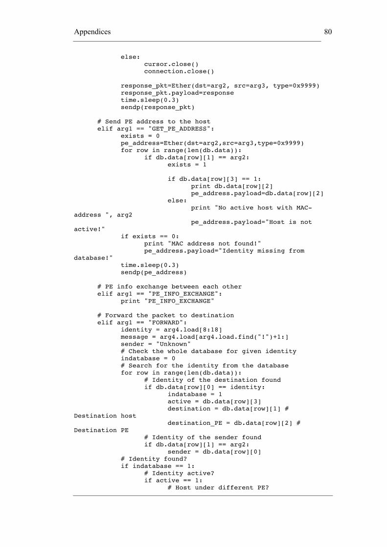
Appendices
80
else: cursor.close() connection.close() response_pkt=Ether(dst=arg2, src=arg3, type=0x9999) response_pkt.payload=response time.sleep(0.3) sendp(response_pkt) # Send PE address to the host elif arg1 == "GET_PE_ADDRESS": exists = 0 pe_address=Ether(dst=arg2,src=arg3,type=0x9999) for row in range(len(db.data)): if db.data[row][1] == arg2: exists = 1 if db.data[row][3] == 1: print db.data[row][2] pe_address.payload=db.data[row][2] else: print "No active host with MAC-address ", arg2 pe_address.payload="Host is not active!" if exists == 0: print "MAC address not found!" pe_address.payload="Identity missing from database!" time.sleep(0.3) sendp(pe_address) # PE info exchange between each other elif arg1 == "PE_INFO_EXCHANGE": print "PE_INFO_EXCHANGE" # Forward the packet to destination elif arg1 == "FORWARD": identity = arg4.load[8:18] message = arg4.load[arg4.load.find("!")+1:] sender = "Unknown" # Check the whole database for given identity indatabase = 0 # Search for the identity from the database for row in range(len(db.data)): # Identity of the destination found if db.data[row][0] == identity: indatabase = 1 active = db.data[row][3] destination = db.data[row][1] # Destination host destination_PE = db.data[row][2] # Destination PE # Identity of the sender found if db.data[row][1] == arg2: sender = db.data[row][0] # Identity found? if indatabase == 1: # Identity active? if active == 1: # Host under different PE?

Appendices
81
if destination_PE != server_address: destination_node = destination_PE # Check the next node! for row in range(len(db2.data)): # Find the next node if (db2.data[row][0] == server_address and db2.data[row][1] == destination_PE): destination_node = db2.data[row][2] # Destination node # Encapsulated packets have EtherType 0x9998! print "Encapsulating and forwarding packet to:",destination_node inner_pkt = Ether(dst = destination, src=destination_PE, type=0x9999) inner_pkt.payload = sender + ": " + message outer_pkt = Ether(dst = destination_node, src=server_address, type=0x9998)/inner_pkt sendp(outer_pkt) else: print "Sending packet to:",destination RE2EE = Ether(dst=destination, src=server_address, type=0x9999) RE2EE.payload = sender + ": " + message time.sleep(0.3) sendp(RE2EE) else: print "Identity is inactive!" reply = Ether(dst=arg2, src=server_address, type=0x9999) reply.payload = "Identity is inactive!" time.sleep(0.3) sendp(RE2EE) else: print "Identity does not exist!" reply = Ether(dst=arg2, src=server_address, type=0x9999) reply.payload = "Identity does not exist!" time.sleep(0.3) sendp(RE2EE) # Decapsulation of the packet and forwarding it to the host elif arg1 == "DELIVER": innerPkt=Ether(arg4.load) if innerPkt.src == arg4.dst: print "Decapsulating and sending packet to:" +innerPkt.dst sendp(innerPkt) else: # Check the next node! for row in range(len(db2.data)): # Find the next node if (db2.data[row][0] == server_address and db2.data[row][1] == innerPkt.src): destination_node = db2.data[row][2] # Destination node
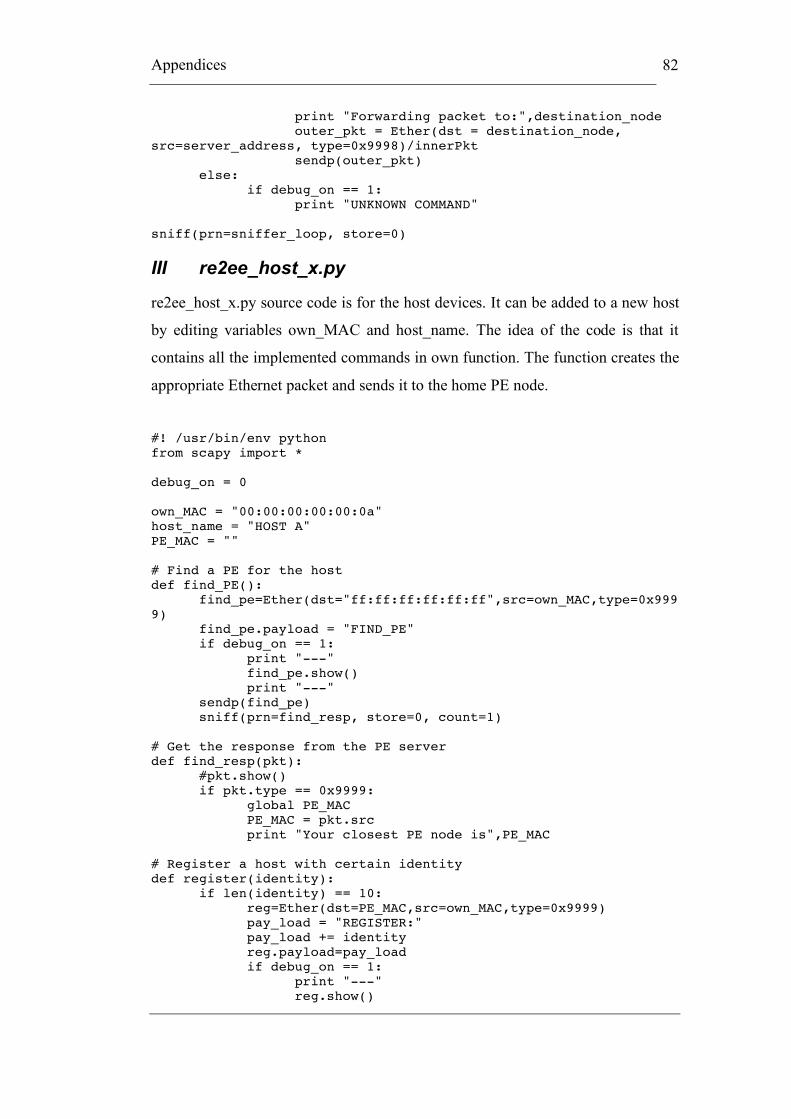
Appendices
82
print "Forwarding packet to:",destination_node outer_pkt = Ether(dst = destination_node, src=server_address, type=0x9998)/innerPkt sendp(outer_pkt) else: if debug_on == 1: print "UNKNOWN COMMAND" sniff(prn=sniffer_loop, store=0)
III re2ee_host_x.py
re2ee_host_x.py source code is for the host devices. It can be added to a new host
by editing variables own_MAC and host_name. The idea of the code is that it
contains all the implemented commands in own function. The function creates the
appropriate Ethernet packet and sends it to the home PE node.
#! /usr/bin/env python from scapy import * debug_on = 0 own_MAC = "00:00:00:00:00:0a" host_name = "HOST A" PE_MAC = "" # Find a PE for the host def find_PE(): find_pe=Ether(dst="ff:ff:ff:ff:ff:ff",src=own_MAC,type=0x9999) find_pe.payload = "FIND_PE" if debug_on == 1: print "---" find_pe.show() print "---" sendp(find_pe) sniff(prn=find_resp, store=0, count=1) # Get the response from the PE server def find_resp(pkt): #pkt.show() if pkt.type == 0x9999: global PE_MAC PE_MAC = pkt.src print "Your closest PE node is",PE_MAC # Register a host with certain identity def register(identity): if len(identity) == 10: reg=Ether(dst=PE_MAC,src=own_MAC,type=0x9999) pay_load = "REGISTER:" pay_load += identity reg.payload=pay_load if debug_on == 1: print "---" reg.show()

Appendices
83
print "---" sendp(reg) sniff(prn=wait_for_answer, store=0, count=1) else: print "Identity must be exactly 10 chars!" def wait_for_answer(pkt): if (pkt.type == 0x9999 and pkt.dst == own_MAC): print pkt.load # Inactive a host def inactivate(identity): ina=Ether(dst=PE_MAC,src=own_MAC,type=0x9999) pay_load = "INACTIVATE:" pay_load += identity ina.payload = pay_load if debug_on == 1: print "---" ina.show() print "---" sendp(ina) sniff(prn=wait_for_answer, store=0, count=1) # Find the PE for certain identity def get_pe_address(identity): get_pe=Ether(dst=PE_MAC,src=own_MAC,type=0x9999) get_pe.payload="GET_PE_ADDRESS" if debug_on == 1: print "---" get_pe.show() print "---" sendp(get_pe) sniff(prn=response, store=0, count=1) # Gets the response from PE query def response(pkt): if pkt.type == 0x9999: print "PE's MAC address is:",pkt.payload def pe_info_exchange(): pe_info_exchange=Ether(dst=PE_MAC,src=own_MAC,type=0x9999) pe_info_exchange.payload="PE_INFO_EXCHANGE" if debug_on == 1: print "---" pe_info_exchange.show() print "---" sendp(pe_info_exchange) # Send a message to certain identity def send_packet(message, identity): send_packet=Ether(dst=PE_MAC,src=own_MAC,type=0x9999) pay_load = "FORWARD:" + identity + "!" + message send_packet.payload=pay_load if debug_on == 1: print "---" send_packet.show() print "---" sendp(send_packet) sniff(prn=wait_for_answer, store=0, count=1) def receive_packets():
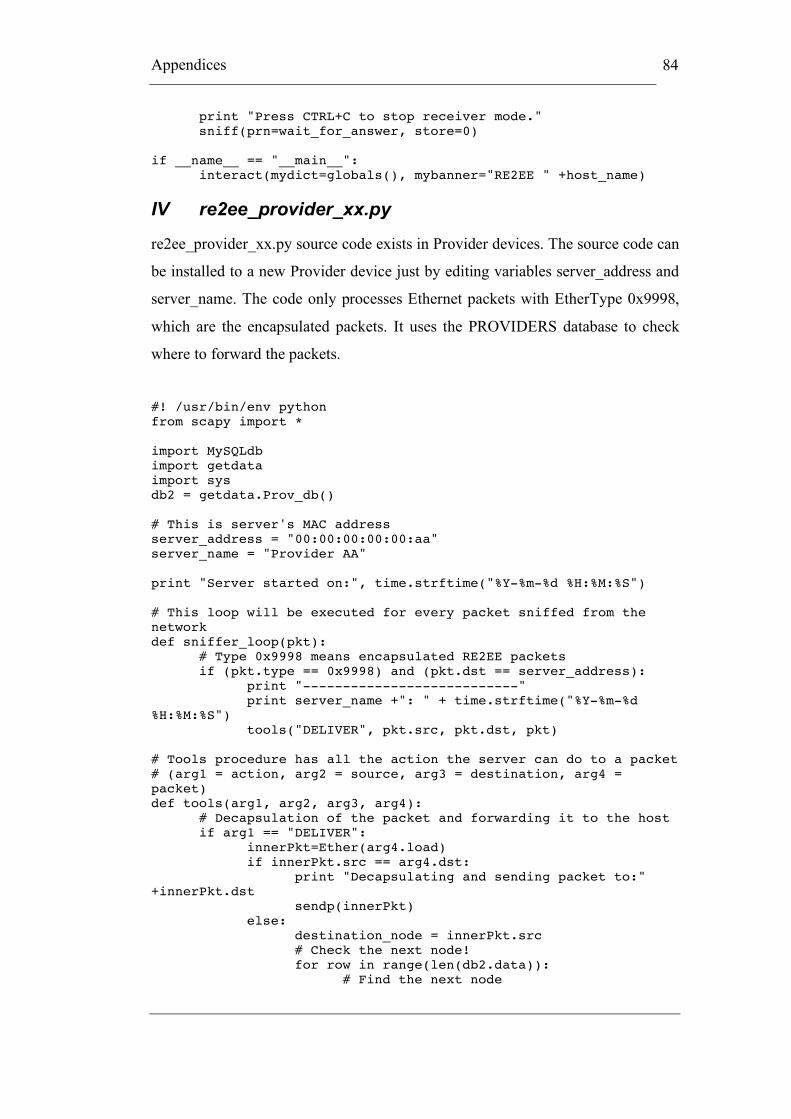
Appendices
84
print "Press CTRL+C to stop receiver mode." sniff(prn=wait_for_answer, store=0) if __name__ == "__main__": interact(mydict=globals(), mybanner="RE2EE " +host_name)
IV re2ee_provider_xx.py
re2ee_provider_xx.py source code exists in Provider devices. The source code can
be installed to a new Provider device just by editing variables server_address and
server_name. The code only processes Ethernet packets with EtherType 0x9998,
which are the encapsulated packets. It uses the PROVIDERS database to check
where to forward the packets.
#! /usr/bin/env python from scapy import * import MySQLdb import getdata import sys db2 = getdata.Prov_db() # This is server's MAC address server_address = "00:00:00:00:00:aa" server_name = "Provider AA" print "Server started on:", time.strftime("%Y-%m-%d %H:%M:%S") # This loop will be executed for every packet sniffed from the network def sniffer_loop(pkt): # Type 0x9998 means encapsulated RE2EE packets if (pkt.type == 0x9998) and (pkt.dst == server_address): print "---------------------------" print server_name +": " + time.strftime("%Y-%m-%d %H:%M:%S") tools("DELIVER", pkt.src, pkt.dst, pkt) # Tools procedure has all the action the server can do to a packet # (arg1 = action, arg2 = source, arg3 = destination, arg4 = packet) def tools(arg1, arg2, arg3, arg4): # Decapsulation of the packet and forwarding it to the host if arg1 == "DELIVER": innerPkt=Ether(arg4.load) if innerPkt.src == arg4.dst: print "Decapsulating and sending packet to:" +innerPkt.dst sendp(innerPkt) else: destination_node = innerPkt.src # Check the next node! for row in range(len(db2.data)): # Find the next node

Appendices
85
if (db2.data[row][0] == server_address and db2.data[row][1] == innerPkt.src): destination_node = db2.data[row][2] # Destination node print "Forwarding packet to:",destination_node outer_pkt = Ether(dst = destination_node, src=server_address, type=0x9998)/innerPkt sendp(outer_pkt) else: if debug_on == 1: print "UNKNOWN COMMAND" sniff(prn=sniffer_loop, store=0)


