
© March 25, 2016 Dr. Lynn Fuller, Professor
Rochester Institute of Technology
Microelectronic Engineering
MEMS Capacitor Sensors
Page 1
ROCHESTER INSTITUTE OF TEHNOLOGY MICROELECTRONIC ENGINEERING
3-25-16 capacitor_sensors.ppt
MEMS Capacitor Sensors
and Signal Conditioning
Dr. Lynn Fuller Dr. FullersWebpage: http://people.rit.edu/lffeee
Electrical and Microelectronic Engineering
Rochester Institute of Technology
82 Lomb Memorial Drive
Rochester, NY 14623-5604
Email: [email protected]
ProgramWwebpage: http://www.microe.rit.edu
© March 25, 2016 Dr. Lynn Fuller, Professor
Rochester Institute of Technology
Microelectronic Engineering
MEMS Capacitor Sensors
Page 2
OUTLINE
Capacitors
Capacitors as Sensors
Chemicapacitor
Diaphragm Pressure Sensor
Condenser Microphone
Capacitors as Electrostatic Actuators
Signal Conditioning
References
Homework

© March 25, 2016 Dr. Lynn Fuller, Professor
Rochester Institute of Technology
Microelectronic Engineering
MEMS Capacitor Sensors
Page 3
CAPACITORS
Capacitor - a two terminal device whose current is proportional to the time rate of change of the applied voltage; I = C dV/dt a capacitor C is constructed of any two conductors separated by an insulator. The capacitance of such a structure is: C = eo er Area/d where eo is the permitivitty of free space er is the relative permitivitty Area is the overlap area of the two conductor separated by distance d
eo = 8.85E-14 F/cm
I
C V
+
-
Area
d er air = 1 er SiO2 = 3.9

© March 25, 2016 Dr. Lynn Fuller, Professor
Rochester Institute of Technology
Microelectronic Engineering
MEMS Capacitor Sensors
Page 4
OTHER CAPACITOR CONFIGURATIONS
C2
C1
C Total = C1C2/(C1+C2)
Two Dielectric Materials between Parallel Plates
Example: A condenser microphone is made from a polysilicon plate 1000 µm
square with 1000Å silicon nitride on it and a second plate of aluminum with a
1µm air gap. Calculate C and C’ if the aluminum plate moves 0.1 µm.
C1= eo 1 (1000E-4)1000E-4/1E-4 = 8.85 pF
C1at 1.1um = 8.05pF or DC1= 0.80 pF
C1at 0.9um = 9.83pF or DC1= 0.98 pF
C2 = eo 7.5(1000E-4)1000E-4/0.1E-4 = 664pF
Ctotal = 8.73pF
DCtotal = 8.73 + (-7.94 or +9.70) pF = -0.79 or +0.97 pF
eo = 8.85E-14 F/cm
er air = 1 er Si3N4 = 7.5
air

© March 25, 2016 Dr. Lynn Fuller, Professor
Rochester Institute of Technology
Microelectronic Engineering
MEMS Capacitor Sensors
Page 5
DIELECTRIC CONSTANT OF SELECTED MATERIALS
Vacuum 1
Air 1.00059
Acetone 20
Barium strontium titanate
500
Benzene 2.284
Conjugated Polymers
6 to 100,000
Ethanol 24.3
Glycerin 42.5
Glass 5-10
Methanol 30
Photoresist 3
Plexiglass 3.4
Polyimide 2.8
Rubber 3
Silicon 11.7
Silicon dioxide 3.9
Silicon Nitride 7.5
Teflon 2.1
Water 80-88
http://www.asiinstruments.com/technical/Dielectric%20Constants.htm
Note: Water has er of 80-88

© March 25, 2016 Dr. Lynn Fuller, Professor
Rochester Institute of Technology
Microelectronic Engineering
MEMS Capacitor Sensors
Page 6
CALCULATIONS

© March 25, 2016 Dr. Lynn Fuller, Professor
Rochester Institute of Technology
Microelectronic Engineering
MEMS Capacitor Sensors
Page 7
OTHER CAPACITOR CONFIGURATIONS
Interdigitated Fingers with Thickness > Space between Fingers
h = height of fingers s = space between fingers N = number of fingers L = length of finger overlap
C = (N-1) eoer L h /s
Example: 200 fingers, h = 2um, s=1um, air
C = 0.35 pF

© March 25, 2016 Dr. Lynn Fuller, Professor
Rochester Institute of Technology
Microelectronic Engineering
MEMS Capacitor Sensors
Page 8
OTHER CAPACITOR CONFIGURATIONS
Interdigitated Fingers with Thickness << Space between Fingers
C = LN 4 eoer p
n=1
0 0 1
2n-1 Jo2 (2n-1)ps
2(s+w)
Jo = zero order Bessel function w = width of fingers s = space between fingers N = number of fingers L = length of finger overlap
Reference:
Lvovich, Liu and Smiechowski,

© March 25, 2016 Dr. Lynn Fuller, Professor
Rochester Institute of Technology
Microelectronic Engineering
MEMS Capacitor Sensors
Page 9
MODELING OF INTERDIGITATED CAPACITOR
N = number of fingers er1
er2
er = er1 + er2
d1
d2
d1 and d2 (interrogation depth)

© March 25, 2016 Dr. Lynn Fuller, Professor
Rochester Institute of Technology
Microelectronic Engineering
MEMS Capacitor Sensors
Page 10
PLANAR INTERDIGITATED SENSOR
dt
tktkK
ws
wk
kK
kKLNC rr
=
=
=
1
0222
2
1
2
021
11
1)(
)(2cos
)(2
])1[()()1(
p
eee
V.F.Lvovich, C.C.Liu, M.F.Smiechowski
Jo is zero order Bessel function
er1
er2
d1
d2
er = er1 + er2

© March 25, 2016 Dr. Lynn Fuller, Professor
Rochester Institute of Technology
Microelectronic Engineering
MEMS Capacitor Sensors
Page 11
er = eoxide
FINGERS ON SILICON SUBSTRATE
C = C fingers + C to substrate / 2
(if silicon substrate is treated as a conductor)
Silicon
SiO2
C fingers
C to Substrate C to Substrate
er1
er = er1
C fingers C substrate
C = eo er area / t
t

© March 25, 2016 Dr. Lynn Fuller, Professor
Rochester Institute of Technology
Microelectronic Engineering
MEMS Capacitor Sensors
Page 12
CALCULATIONS
Note: er = er1 + er2 is for the material above/below the fingers if both are insulators a few times thicker than the space between fingers

© March 25, 2016 Dr. Lynn Fuller, Professor
Rochester Institute of Technology
Microelectronic Engineering
MEMS Capacitor Sensors
Page 13
OTHER CAPACITOR CONFIGURATIONS
Two Long Parallel Wires Surrounded by Dielectric Material
C/L = 12.1 er / (log [(h/r) + ((h/r)2-1)1/2]
h = half center to center space r = conductor radius (same units as h)
Capacitance per unit length C/L
Reference: Kraus and Carver
Example: Calculate the capacitance of a meter long connection of parallel wires.
Solution: let, h = 1 mm, r = 0.5mm, plastic er = 3 the equation above gives
C/L = 63.5 pF/m
C = 63.5 pF
© March 25, 2016 Dr. Lynn Fuller, Professor
Rochester Institute of Technology
Microelectronic Engineering
MEMS Capacitor Sensors
Page 14
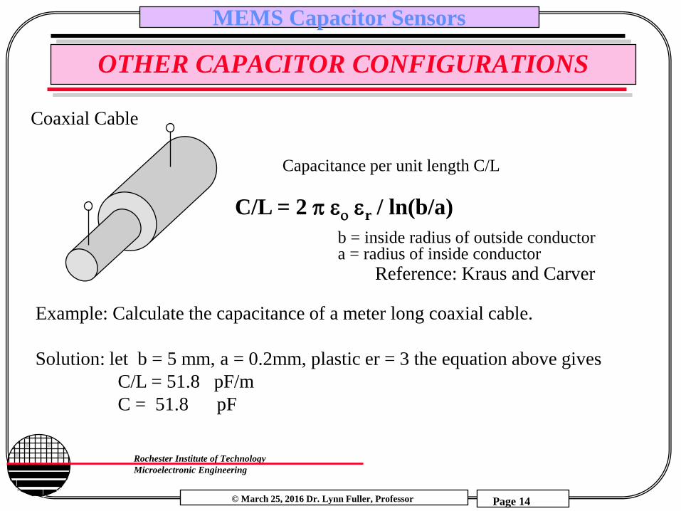
OTHER CAPACITOR CONFIGURATIONS
Coaxial Cable
C/L = 2 p eo er / ln(b/a)
b = inside radius of outside conductor a = radius of inside conductor
Capacitance per unit length C/L
Reference: Kraus and Carver
Example: Calculate the capacitance of a meter long coaxial cable.
Solution: let b = 5 mm, a = 0.2mm, plastic er = 3 the equation above gives
C/L = 51.8 pF/m
C = 51.8 pF

© March 25, 2016 Dr. Lynn Fuller, Professor
Rochester Institute of Technology
Microelectronic Engineering
MEMS Capacitor Sensors
Page 15
CAPACITORS AS POSITION SENSORS
C d
C1
C2
C
d
C1
d
C2
One plate moves relative to other changing gap (d)
One plate moves relative to other
changing overlap area (A)
Center plate moves relative to the two
fixed plates
Top plate moves changing C1 and C2 differentially

© March 25, 2016 Dr. Lynn Fuller, Professor
Rochester Institute of Technology
Microelectronic Engineering
MEMS Capacitor Sensors
Page 16
CAPACITORS AS SENSORS
Change in Space Between Plates (d) Change in Area (A)
Change in Dielectric
Constant (er)
microphone gyroscope
Oil level sensor or
position sensor
© March 25, 2016 Dr. Lynn Fuller, Professor
Rochester Institute of Technology
Microelectronic Engineering
MEMS Capacitor Sensors
Page 17
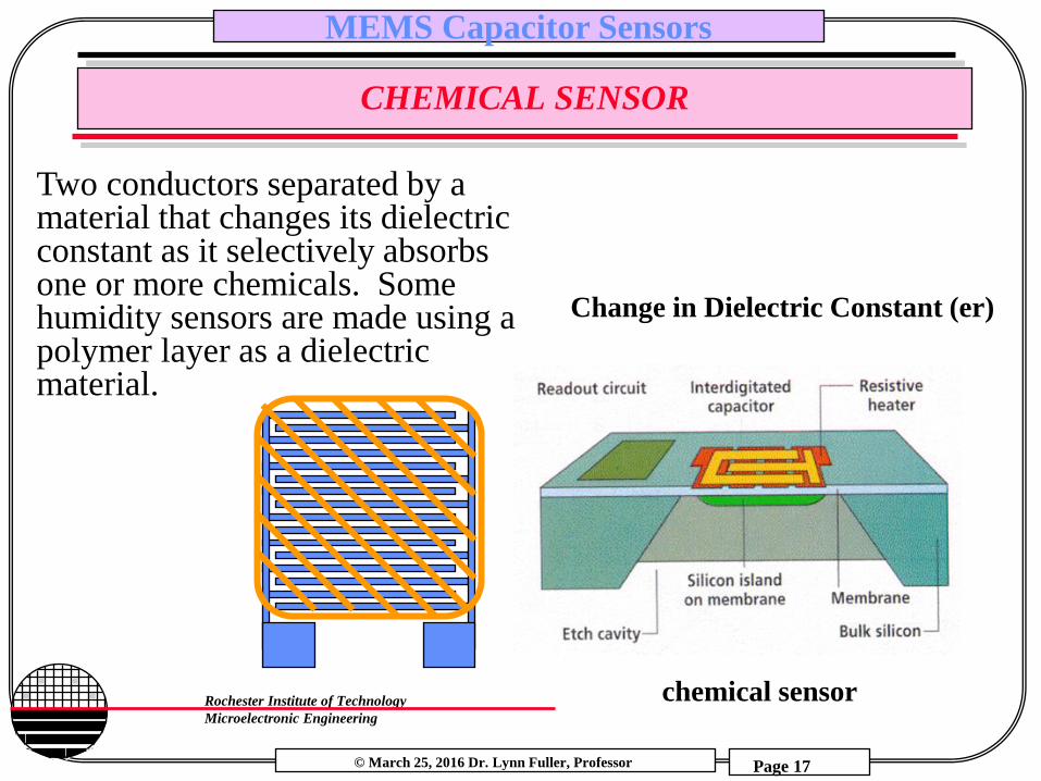
CHEMICAL SENSOR
Two conductors separated by a material that changes its dielectric constant as it selectively absorbs one or more chemicals. Some humidity sensors are made using a polymer layer as a dielectric material.
Change in Dielectric Constant (er)
chemical sensor

© March 25, 2016 Dr. Lynn Fuller, Professor
Rochester Institute of Technology
Microelectronic Engineering
MEMS Capacitor Sensors
Page 18
DIAPHRAGM PRESSURE SENSOR
Diaphragm:
Displacement
Uniform Pressure (P)
Radius (R)
diaphragm
thickness ()
Displacement (y)
E = Young’s Modulus, = Poisson’s Ratio
for Aluminum =0.35
Equation for deflection at center of diaphragm
y = 3PR4[(1/)2-1]
16E(1/)23
= (249.979)PR4[(1/)2-1]
E(1/)23
*The second equation corrects all units
assuming that pressure is mmHg,
radius and diaphragm is m, Young’s
Modulus is dynes/cm2, and the
calculated displacement found is m.
Mechanics of Materials, by Ferdinand P. Beer

© March 25, 2016 Dr. Lynn Fuller, Professor
Rochester Institute of Technology
Microelectronic Engineering
MEMS Capacitor Sensors
Page 19
DIAPHRGM WITH CAPTURED VOLUME
F1 = force on diaphragm = external pressure times area of diaphragm F2 = force due to captured volume of air under the diaphragm F3 = force to mechanically deform the diaphragm
h d
rs
rd
PV = nRT
F1= F2 + F3 F1 = P x Ad F2 = nRT Ad / (Vd + Vs)
where Vd = Ad (d-y) and Vs = G1 Pi (rs2 – rd2)(d) where
G1 is the % of spacer that is not oxide
F3 = (16 E (1/ )2 h3 y)/(3 rd4[(1/ )2-1])
F1
F2 + F3 Ad y
h
d

© March 25, 2016 Dr. Lynn Fuller, Professor
Rochester Institute of Technology
Microelectronic Engineering
MEMS Capacitor Sensors
Page 20
DIAPHRAGM WITH CAPTURED VOLUME
y (µm) P (N/m2)
0 0
0.1 5103.44
0.2 10748.09
0.3 17025.03
0.4 24047
0.5 31955.23
0.6 40929.06
0.7 51199.69
0.8 63070.47
0.9 76947.31
1 93386.12
1.1 113169.1
1.2 137433.1
1.3 167895.7
1.4 207281.3
1.5 260184.8
1.6 335009.7
1.7 448945.4
1.8 643513.4
1.9 1051199
2 2446196
P (N/m2) vs displacement y (µm)
0
500000
1000000
1500000
2000000
2500000
3000000
0 0.5 1 1.5 2 2.5

© March 25, 2016 Dr. Lynn Fuller, Professor
Rochester Institute of Technology
Microelectronic Engineering
MEMS Capacitor Sensors
Page 21
CONDENSER MICROPHONE
1 µm Aluminum
2.0 µm Gap
ALUMINUM DIAPHRAGM

© March 25, 2016 Dr. Lynn Fuller, Professor
Rochester Institute of Technology
Microelectronic Engineering
MEMS Capacitor Sensors
Page 22
ALUMINUM DIAPHRAGM PRESSURE SENSOR
Diaphragm
Drain
Source Gate
Bottom
Plate
Si Wafer
Insulator Contact
Air Gap (~1 atm)
Kerstin Babbitt - University of Rochester
Stephanie Bennett - Clarkson University
Sheila Kahwati - Syracuse University
An Pham - Rochester Institute of Technology
© March 25, 2016 Dr. Lynn Fuller, Professor
Rochester Institute of Technology
Microelectronic Engineering
MEMS Capacitor Sensors
Page 23
SIGNAL CONDITIONING FOR CAPACITOR SENSORS
Delta Capacitance to AC Voltage
Static Capacitance to DC Voltage
Capacitance to Current
Ring Oscillator Capacitance to Frequency
RC Oscillator Capacitance to Frequency
Frequency to Digital
Capacitance to Analog Voltage to Digital
Other
Wireless
© March 25, 2016 Dr. Lynn Fuller, Professor
Rochester Institute of Technology
Microelectronic Engineering
MEMS Capacitor Sensors
Page 24
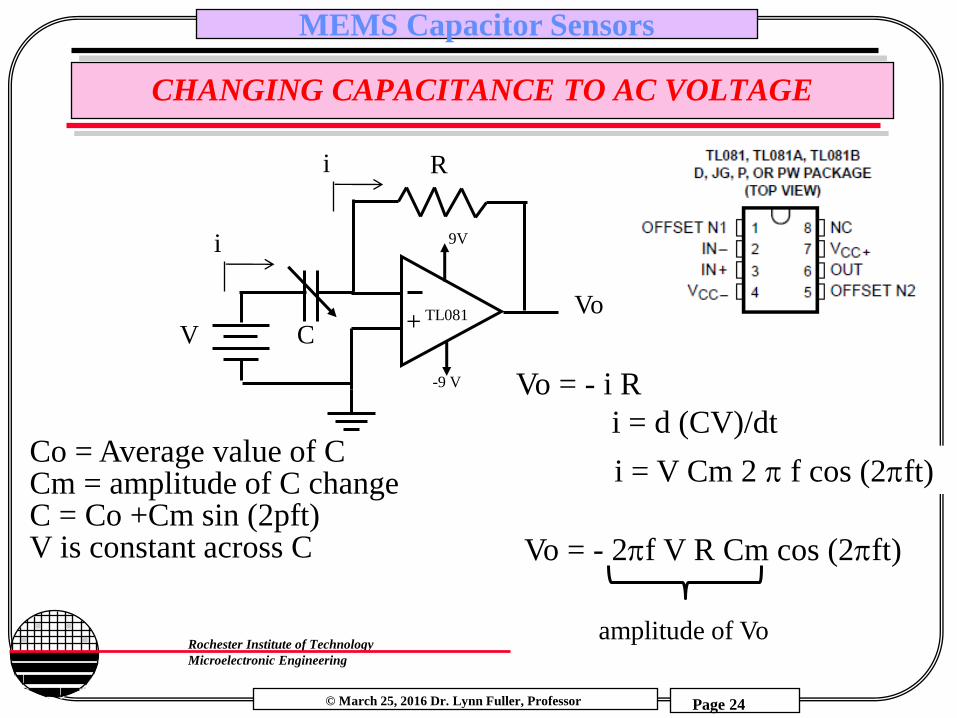
CHANGING CAPACITANCE TO AC VOLTAGE
+
9V
-9 V
TL081
i
V
R
C Vo
i
i = V Cm 2 p f cos (2pft) Co = Average value of C Cm = amplitude of C change C = Co +Cm sin (2pft) V is constant across C
Vo = - i R
i = d (CV)/dt
Vo = - 2pf V R Cm cos (2pft)
amplitude of Vo
© March 25, 2016 Dr. Lynn Fuller, Professor
Rochester Institute of Technology
Microelectronic Engineering
MEMS Capacitor Sensors
Page 25
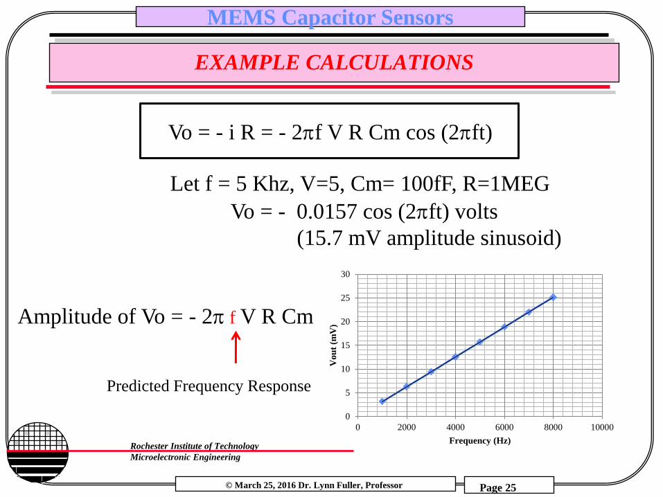
EXAMPLE CALCULATIONS
Vo = - i R = - 2pf V R Cm cos (2pft)
Let f = 5 Khz, V=5, Cm= 100fF, R=1MEG
Vo = - 0.0157 cos (2pft) volts
(15.7 mV amplitude sinusoid)
0
5
10
15
20
25
30
0 2000 4000 6000 8000 10000
Vo
ut
(mV
)
Frequency (Hz)
Predicted Frequency Response
Amplitude of Vo = - 2p f V R Cm

© March 25, 2016 Dr. Lynn Fuller, Professor
Rochester Institute of Technology
Microelectronic Engineering
MEMS Capacitor Sensors
Page 26
SPICE CHANGING CAPACITANCE TO AC VOLTAGE
© March 25, 2016 Dr. Lynn Fuller, Professor
Rochester Institute of Technology
Microelectronic Engineering
MEMS Capacitor Sensors
Page 27
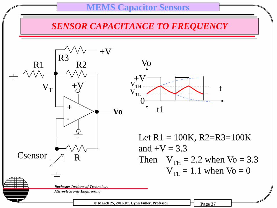
SENSOR CAPACITANCE TO FREQUENCY
-
+ Vo
Csensor
+V
R2 R1
R
VT
+V R3
Vo
t
t1
+V
0
Let R1 = 100K, R2=R3=100K
and +V = 3.3
Then VTH = 2.2 when Vo = 3.3
VTL = 1.1 when Vo = 0
VTH
VTL
© March 25, 2016 Dr. Lynn Fuller, Professor
Rochester Institute of Technology
Microelectronic Engineering
MEMS Capacitor Sensors
Page 28
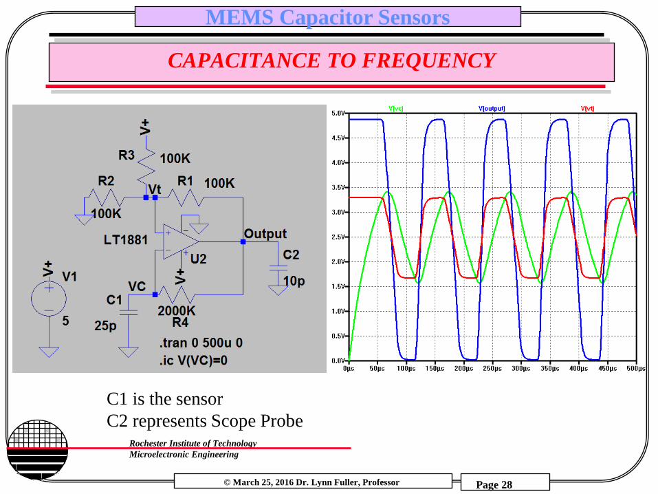
CAPACITANCE TO FREQUENCY
C1 is the sensor
C2 represents Scope Probe
© March 25, 2016 Dr. Lynn Fuller, Professor
Rochester Institute of Technology
Microelectronic Engineering
MEMS Capacitor Sensors
Page 29
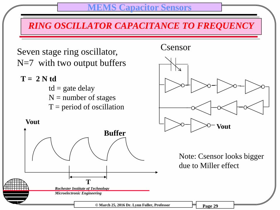
RING OSCILLATOR CAPACITANCE TO FREQUENCY
T = 2 N td
td = gate delay
N = number of stages
T = period of oscillation
Seven stage ring oscillator,
N=7 with two output buffers
T
Vout
Buffer Vout
Csensor
Note: Csensor looks bigger
due to Miller effect

© March 25, 2016 Dr. Lynn Fuller, Professor
Rochester Institute of Technology
Microelectronic Engineering
MEMS Capacitor Sensors
Page 30
RING OSCILLATOR CAPACITANCE TO FREQUENCY
3 stage ring oscillator – no buffers

© March 25, 2016 Dr. Lynn Fuller, Professor
Rochester Institute of Technology
Microelectronic Engineering
MEMS Capacitor Sensors
Page 31
CAPACITANCE TO VOLTAGE
+
i
R
C
i
Vo = - i R
Vo = 2pf Vm R C cos (2pft)
amplitude of Vo
i = C d(Vm sin (2pft))/dt
Vin = Vm sin (2pft)
i = dQ/dt = d (CV)/dt = C dV/dt
Example: R = 2MEG, C = 2pF, Vm = .5 V, f = 100 Khz
Vo = 0.4 volts peak-to-peak

© March 25, 2016 Dr. Lynn Fuller, Professor
Rochester Institute of Technology
Microelectronic Engineering
MEMS Capacitor Sensors
Page 32
CAPACITANCE TO VOLTAGE – BLOCK DIAGRAM
+
i
R
C
i
Vin
Vout -
+
AC Vout p-p depends
on Value of C Buffer Peak Detector

© March 25, 2016 Dr. Lynn Fuller, Professor
Rochester Institute of Technology
Microelectronic Engineering
MEMS Capacitor Sensors
Page 33
CAPACITANCE TO VOLTAGE
Buffer
Peak Detector

© March 25, 2016 Dr. Lynn Fuller, Professor
Rochester Institute of Technology
Microelectronic Engineering
MEMS Capacitor Sensors
Page 34
STATIC CAPACITANCE TO VOLTAGE
© March 25, 2016 Dr. Lynn Fuller, Professor
Rochester Institute of Technology
Microelectronic Engineering
MEMS Capacitor Sensors
Page 35
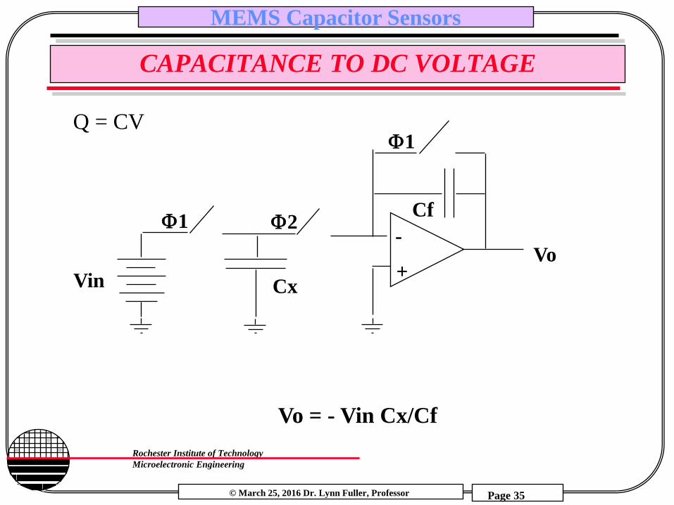
CAPACITANCE TO DC VOLTAGE
Vin
Cf
Cx
-
+ Vo
1
1 2
Vo = - Vin Cx/Cf
Q = CV

© March 25, 2016 Dr. Lynn Fuller, Professor
Rochester Institute of Technology
Microelectronic Engineering
MEMS Capacitor Sensors
Page 36
SPICE FOR CAPACITANCE TO DC VOLTAGE
Q = CV

© March 25, 2016 Dr. Lynn Fuller, Professor
Rochester Institute of Technology
Microelectronic Engineering
MEMS Capacitor Sensors
Page 37
WIRELESS REMOTE SENSING OF L OR C
C
L
R
I
f
I
Capacitive Pressure Sensor
~ 13MHz
Exte
rnal
Ele
ctro
nic
s
Antenna

© March 25, 2016 Dr. Lynn Fuller, Professor
Rochester Institute of Technology
Microelectronic Engineering
MEMS Capacitor Sensors
Page 38
BLOCK DIAGRAM FOR REMOTE SENSING ELECTRONICS
Digital Controlled Oscillator
Filter
RS 232 To
Display
Microchip PIC18F452
µP
R
I
Antenna
Gnd
-
+
Power Amp
A to D
Amp
Memory
C
L
Remote Resonant
LC
© March 25, 2016 Dr. Lynn Fuller, Professor
Rochester Institute of Technology
Microelectronic Engineering
MEMS Capacitor Sensors
Page 39
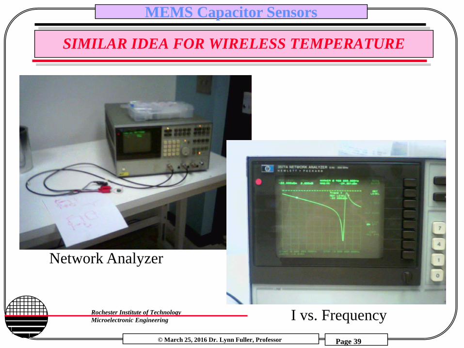
SIMILAR IDEA FOR WIRELESS TEMPERATURE
Network Analyzer
I vs. Frequency
© March 25, 2016 Dr. Lynn Fuller, Professor
Rochester Institute of Technology
Microelectronic Engineering
MEMS Capacitor Sensors
Page 40
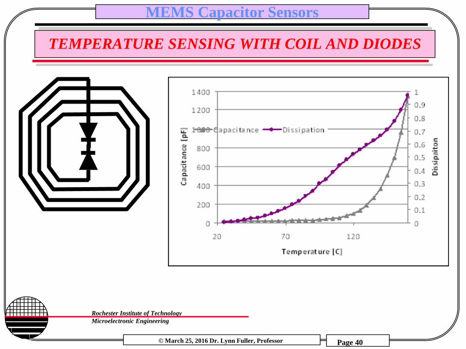
TEMPERATURE SENSING WITH COIL AND DIODES

© March 25, 2016 Dr. Lynn Fuller, Professor
Rochester Institute of Technology
Microelectronic Engineering
MEMS Capacitor Sensors
Page 41
PICKUP COIL CURRENT
Due to nearby LC
No Resonant Circuit Present Resonant LC Circuit Present

© March 25, 2016 Dr. Lynn Fuller, Professor
Rochester Institute of Technology
Microelectronic Engineering
MEMS Capacitor Sensors
Page 42
ZOOM IN ON RESONANCE DUE TO LC
Frequency at Which this Dip Occurs
Changes with Temperature
Resonant Frequency
wo = 1/(LC)0.5
fo = wo/2p

© March 25, 2016 Dr. Lynn Fuller, Professor
Rochester Institute of Technology
Microelectronic Engineering
MEMS Capacitor Sensors
Page 43
COMMERCIAL CHIPS
MS3110 Universal Capacitive Read-out IC (left)
and its block diagram (right). capable of sensing
capacitance changes down to 4.0 aF/rtHz, typical

© March 25, 2016 Dr. Lynn Fuller, Professor
Rochester Institute of Technology
Microelectronic Engineering
MEMS Capacitor Sensors
Page 44
SIGNAL CONDITIONING BUILDING BLOCKS
Operational Amplifier
Analog Switches
Non-Overlapping Clock

© March 25, 2016 Dr. Lynn Fuller, Professor
Rochester Institute of Technology
Microelectronic Engineering
MEMS Capacitor Sensors
Page 45
CMOS OPERATIONAL AMPLIFIER

© March 25, 2016 Dr. Lynn Fuller, Professor
Rochester Institute of Technology
Microelectronic Engineering
MEMS Capacitor Sensors
Page 46
ANALOG SWITCHES
For current flowing to the right (ie V1>V2) the PMOS transistor will be on if V1 is greater than the
threshold voltage, the NMOS transistor will be on if V2 is <4 volts. If we are charging up a capacitor
load at node 2 to 5 volts, initially current will flow through NMOS and PMOS but once V2 gets
above 4 volts the NMOS will be off. If we are trying to charge up V2 to V1 = +1 volt the PMOS will
never be on. A complementary situation occurs for current flow to the left. Single transistor switches
can be used if we are sure the Vgs will be more than the threshold voltage for the specific circuit
application. (or use larger voltages on the gates)
NMOS
Vt=+1
PMOS
Vt= -1
D S
I
zero
V1 V2
+5
S D
© March 25, 2016 Dr. Lynn Fuller, Professor
Rochester Institute of Technology
Microelectronic Engineering
MEMS Capacitor Sensors
Page 47
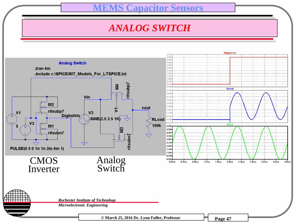
ANALOG SWITCH
CMOS Inverter
Analog Switch

© March 25, 2016 Dr. Lynn Fuller, Professor
Rochester Institute of Technology
Microelectronic Engineering
MEMS Capacitor Sensors
Page 48
TWO PHASE NON OVERLAPPING CLOCK
Switch capacitor circuits require some switches to be open before
others are closed. Thus a need for non-overlapping clocks. The
time delays t1, t2, t3 enable the non-overlapping feature.
1
2
CLK 1
2 t3
t2
t1
S
R
Q
© March 25, 2016 Dr. Lynn Fuller, Professor
Rochester Institute of Technology
Microelectronic Engineering
MEMS Capacitor Sensors
Page 49
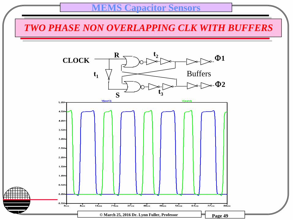
TWO PHASE NON OVERLAPPING CLK WITH BUFFERS
CLOCK 1
2 t3
t2
t1
S
R
Buffers

© March 25, 2016 Dr. Lynn Fuller, Professor
Rochester Institute of Technology
Microelectronic Engineering
MEMS Capacitor Sensors
Page 50
TWO PHASE NON OVERLAPPING CLK WITH BUFFERS
© March 25, 2016 Dr. Lynn Fuller, Professor
Rochester Institute of Technology
Microelectronic Engineering
MEMS Capacitor Sensors
Page 51
REFERENCES
1. Mechanics of Materials, by Ferdinand P. Beer, E. Russell Johnston, Jr., McGraw-Hill Book Co.1981, ISBN 0-07-004284-5
2. Electromagnetics, by John D Kraus, Keith R. Carver, McGraw-Hill Book Co.1981, ISBN 0-07-035396-4
3. Fundamentals of Microfabrication, M. Madou, CRC Press, New York, 1997
4. Switched Capacitor Circuits, Phillip E. Allen and Edgar Sanchez-Sinencio, Van Nostrand Reinhold Publishers, 1984.
5. “Optimization and fabrication of planar interdigitated impedance sensors for highly resistive non-aqueous industrial fluids”, Lvovich, liu and Smiechowski, Sensors and Actuators B:Chemical, Volume 119, Issue 2, 7 Dec. 2006, pgs 490-496.

© March 25, 2016 Dr. Lynn Fuller, Professor
Rochester Institute of Technology
Microelectronic Engineering
MEMS Capacitor Sensors
Page 52
HOMEWORK – MEMS CAPACITOR SENSORS
1. Calculate the capacitance for a round plate of 100µm diameter
with an air gap space of 2.0 µm.
2. If the capacitor in 1 above has the air gap replaced by water
what will the capacitance be?
3. Design an apparatus that can be used to illustrate the attractive
force between two parallel plates when a voltage is applied.
4. Design an electronic circuit that can measure the capacitance of
two metal plates (the size of a quarter) separated by a thin foam
insulator for various applied forces.


