ROAD RESEARCH LABORATORY
Ministry of Transport
RRL REPORT LR 296
INSTRUMENTATION OF THE FULL-SCALE EXPERIMENT ON
A1 TRUNK ROAD AT CONINGTON, HUNTINGDONSHIRE
b y
J. F. Potter, H. C. Mayhew
and A. P. Mayo
Structural Properties
Road Research Laboratory
Crowthorne, Berkshire
1969
CONTENTS
Abstract
i. Introduction
2. Description of instrumented sections
3. Description of gauges
3.1 Soil stress gauges
3.2 Soil strain gauge
3.3 Gauges for measuring strains in the base or surfacing layers
3.4 Deformation gauge
4. Installation of gauges
5. Preliminary tests
6. Proposed test programme
7. Acknowledgements
8. References
9. Appendix 1
Gauge layout on the instrumented sections
iO. Appendix 2
Details of the road construction in the region of the gauges
Page
1
1
2
2
2
4
4
5
6
8
I0
iO
ii
12
12
39
39
O CROWN COPYRIGHT 1969
Extracts from the text may be reproduced provided the source is acknowledged
F
Ownership of the Transport Research Laboratory was transferred from the Department of Transport to a subsidiary of the Transport Research Foundation on !s t April 1996.
This report has been reproduced by permission of the Controller of HMSO. Extracts from the text may be reproduced, except for commercial purposes, provided the source is acknowledged.
~ 1 ¸ .
INSTRUMENTATION OF THE FULL-SCALE EXPERIMENT ON.AI TRUNK ROAD AT CONINGTON, HUNTINGDONSHIRE
ABSTRACT
This paper describes theinstrumentation of the full scale experiment on the south bound carriageway of the A1 trunk road at Conington, Huntingdonshire. The experiment.is designed to compare the performance of various~gravel aggregates used in the base and base course layers in conjunction with bitumen and tar binders.
A brief description is g,iven of the gauges used to measure transient stresses and strains in the sub- grade, strain at the bottom of the base and the sur- facing, and the total and component transient and permanent deformations of the pavement and subgrade. Themethods used for installing these gauges are described in detail and results are given of pre- liminary measurements made when the road wasloaded by commercial vehicles.
Two appendices are included, one giving the gauge lay-out on the instrumented sections and the other giving details of the roadconstruction in the region of the gauges.
I. INTRODUCTION
Since 1968 the Road Research Laboratory has been engaged in an experiment designed to compare the performance of various types of base and base course material used in a trunk road and subjected to normal traffic. The experiment is taking place on the south-bound carriageway of the A1 trunk road at Conington, Huntingdonshire. It consists of thirty experi- mental sections each 34m long, laid on a heavy clay soil. Ten of these sections havebeeninstrumented~withstress, strainand deformation gauges for the observation of their dynamic behaviour. This will be related to their long termperformance under traffic as measuredby the development of permanent deformation. Measurements will be made at intervals of six months using a lorry to apply a fixed wheel load to the sections. All the surfacings and most of the bases were constructed using viscoelastic binders and therefore all comparative tests have to be made at the same vehicle speed and road temperature. Measurements will also be made at various,temperatures andvehiclespeeds so that the effect of these parameters may be found and the results compared with thetheoretical values predicted by elastic theory.
Thestresses, strainsand deformations generated by ordinar/
commercial traffic passing along the road will also be measured. It is intended to study the effect on these quantities of various vehicle wheel configurations by taking measurements in conjunction with a dynamic weighbridge.(I)
2. DESCRIPTION OF INSTRUMENTED SECTIONS
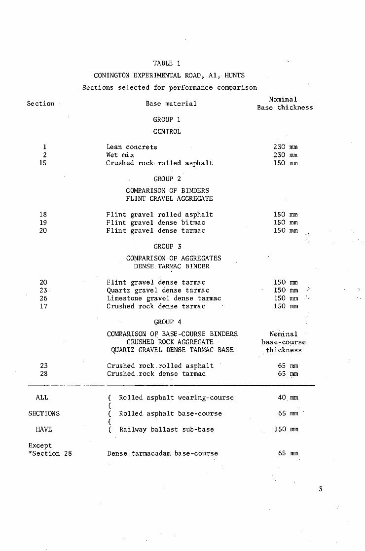
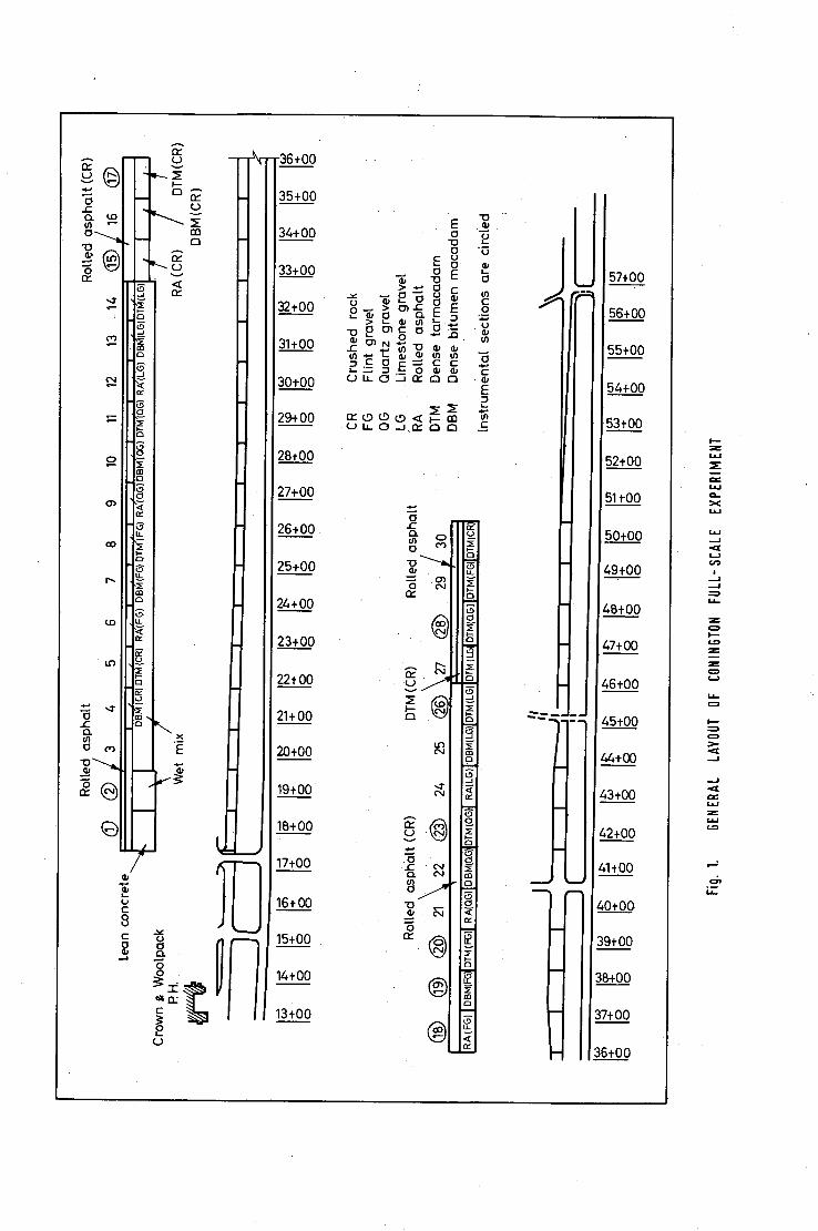
The general layout of the experiment andthematerials used for the various layers of the construction are shown in fig. i. Sections l, 2, 15, 17,18, 19, 20, 25, 26 and 28 have been instrumented. The constituent materials of these ten .sections and their nominal thickness are given in Table I. Group 1 is a control group~consisting of three commonly used base materials. The crushed rock rolled asphalt base represents the material which is expected to have the longest lifeunder traffic. The lean concrete and wet-mix bases have also been previously investigated and it is possible to determine their in-situ elastic properties using the surface wave method.(2) Group 2 was chosen so that a comparison of performance of the various types of binder could be made (i.e. asphalt, bitumen and tar) using one type of aggregate, flint gravel. Group 5 was chosen so that a comparison of the various aggregates could be made, (i.e. flint gravel, quar.tz gravel, lime- stone gravel and crushed rock) using dense tar-macadam binder. Comparison of the performance of rolled asphalt and dense tarmacadam.base course in sections 25 and 28 will be made using only transient deformation gauges.
3. DESCRIPTION OF GAUGES
The soil stresses are measuredby piezoelectricgauges , the soil strains and surfacedeflections by variable reluctance:linear displacement transducers, and the strains in the base by foil resistive strain gauges.
3 . 1 S o i l s t r e s s g a u g e s
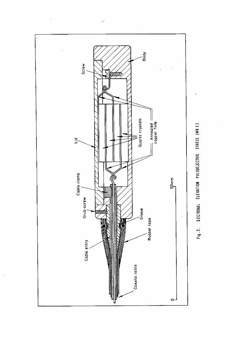
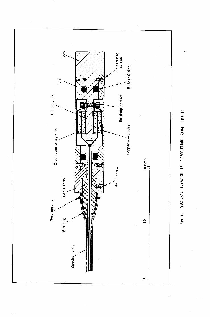
Two designs of soil stress gauge are used in this experiment, both Utilise piezoelectric quartz crystals as the sensitive element. The Mk.l gauge(5) is used for the measurement of the.vertical ~omponent of stress in the soil and is shown in fig. 2. The Mk. II gauge[4) ~ is a redesigned version which can measure small stresses normal to the active face in the presence of large radial stresses. (fig. 3). This second gauge there- fore is used to measure the horizontal componentsof stress in the soil. The overall dimensions of the gauges are 76mm diameter by 17mm thick, and lOlmm diameter by 19.8mm thick respectively.
The principal of operation of both gauges is identical and the same electronic apparatus is:used to measure the output signals. When pressure is applied to the faces of the gauges, the X-cut quartz crystals suffer a minute distortion and an electric charge is produced on the faces of each crystal. The quartz crystals are cut in the form of discs 25mm diameter x 3.1mm thick. The discs are interleaved with copper foils which are wired in parallel and.the faces producing a negative charge under pressure are connected to the inner conductor of the co- axial cable. The facespr0ducing a positive charge.are connected to
Section
I 2
15
18 19 20
20 23 26 17
23 28
TABLE i
CONINGTON EXPERIME~AL ROAD, AI,. HUNTS
Sections selected for performance comparison
Base material
GROUP I
CONTROL
Lean concrete Wet mix Crushed. rock rolled asphalt
GROUP 2
COMPARISON OF BINDERS FLINT GRAVEL AGGREGATE
Flint gravel rolled asphalt Flint gravel dense bitmac Flint gravel dense tarmac
GROUP 3
COMPARISON OF AGGREGATES DENSE.TARMAC BINDER
Flint gravel dense tarmac. Quartz gravel dense tarmac Limestone gravel dense tarmac Crushed rock dense tarmac '
GROUP4
COMPARISON OF BASE-COURSE BINDERS. CRUSHEDROCK AGGREGATE
QUARTZ GRAVEL DENSE TARMAC BASE
Crushed rock.rolled asphalt Crushed.rock dense tarmac
Nominal Base thickness
230 mm 230 nun 150 mm
150 mm 150 nun 150 mm
"2
150 mm 150 mm ~ 150 mm ~,~ 150 nun
Nominal base'course thickness
65 mm 65 mm
ALL
SECTIONS
HAVE
Except *Section 28
( Rolled asphalt wearing-course ( ( Rolled asphalt base-course ( ( Railway ballast sub-base
Dense.tarmacadam base-course
40 mm
65 mm
150 mm
65 mm
3
the gauge body and thence to the metallic braiding of tke cable.- The crystals and the co-axial cable have a capacitance of.about IO00pF and the electric charge produced on the crystal faces causes a voltage to appear across the end of the cable. ~is voltage is proportional to thepressure applied.to the faces of the stress gauge. The gauge bodies are manufactured from aluminium alloy which is anodised to pre- vent .corrosion when buried in *he soil. The lids.of both designs of gauge are sealed to prevent ingress of moisture.
3.2 Soil strain gauge
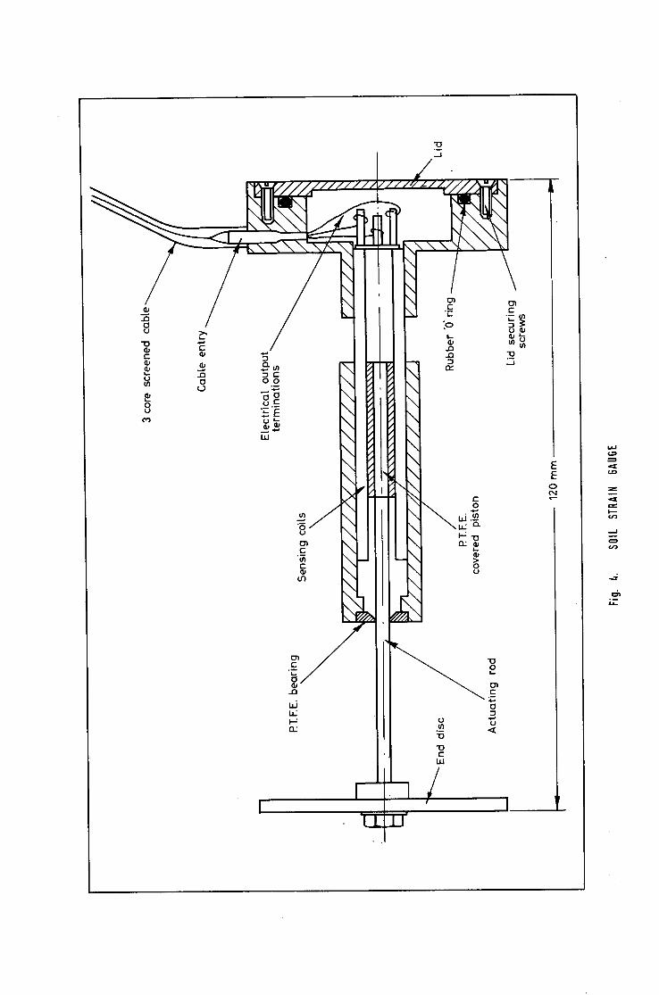
The soil strain gauge (5), which is capableof measuring both dynamic and long term strains, is shown in fig.4. It consists of two aluminium alloy flanges 63mm in diameter attached to either end of a modified variable reluctance transducer. Thetwoflanges form anchor- ages with the soil and, when the soil is strained, the flanges suffer relative displacement. The thinner flange is connected to the core of the transducer and the thicker flange which houses the cable connec- tions is connected to the housing of the transformer coils. When the soft iron core is moved with respect to the coils, the inductance of the coils is altered. The displacement of the flanges is calculated from the change in inductance meas~ redusing an inductance bridge. The gauge can be embedded in the soil to measure strain in any desired orientation.
5.3~ Gauges for measuring straina in the base of surfacinglazers
Two designs.of gauges are used for the.measurement.of transverse and longitudinal strain.at the bottom of the road base. Both designs utilise resistive foil strain gauges as their active elements.
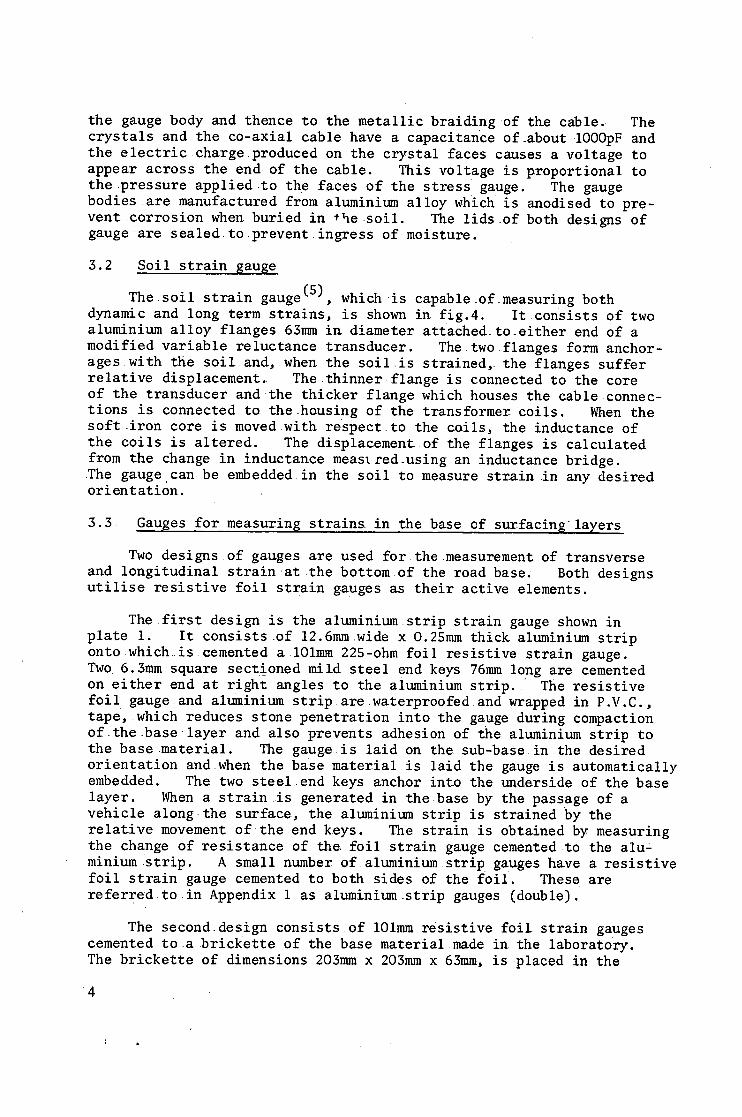
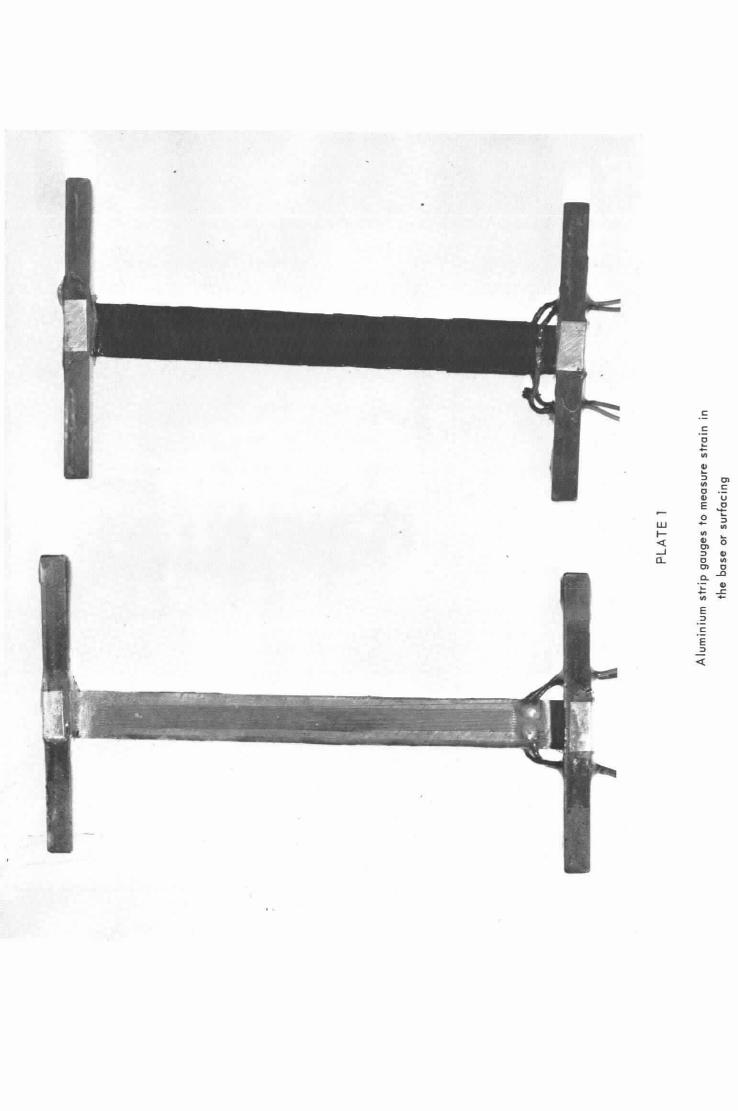
The first design is the aluminium strip strain gauge shown in plate i. It consists _of 12.6mm wide x 0.25mm thick aluminium strip onto which is cemented a lOlmm 225-ohm foil resistive strain gauge. Two, 6.3mmsquare sectioned mild steel end keys 76mm long are cemented on either end at right angles to the aiuminium strip. The resistive foil gauge.and.aluminium strip.arewaterproofed.and wrapped in P.V.C., tape, which reduces stone penetration into the gauge during compaction of.the.baselayer and also prevents adhesion of the aluminium strip to the base material. The gauge is laid on the sub-base in the desired orientation and.when the base material is laid the gauge is automatically embedded. The two steelend keys anchor into the underside of the base layer. When a strain.is generated in the base by the passage of a vehicle along.the surface, the aluminium strip is strained by the relative movement of theend keys. The strain is obtained by measuring the change of resistance of the, foil strain gauge cemented to the alu ~ minium strip. A small number of aluminium strip gauges ha~e a resistive foil strain gauge cemented toboth sides of the f0il. These are referred.to in Appendix 1 as aluminium.strip gauges {double).
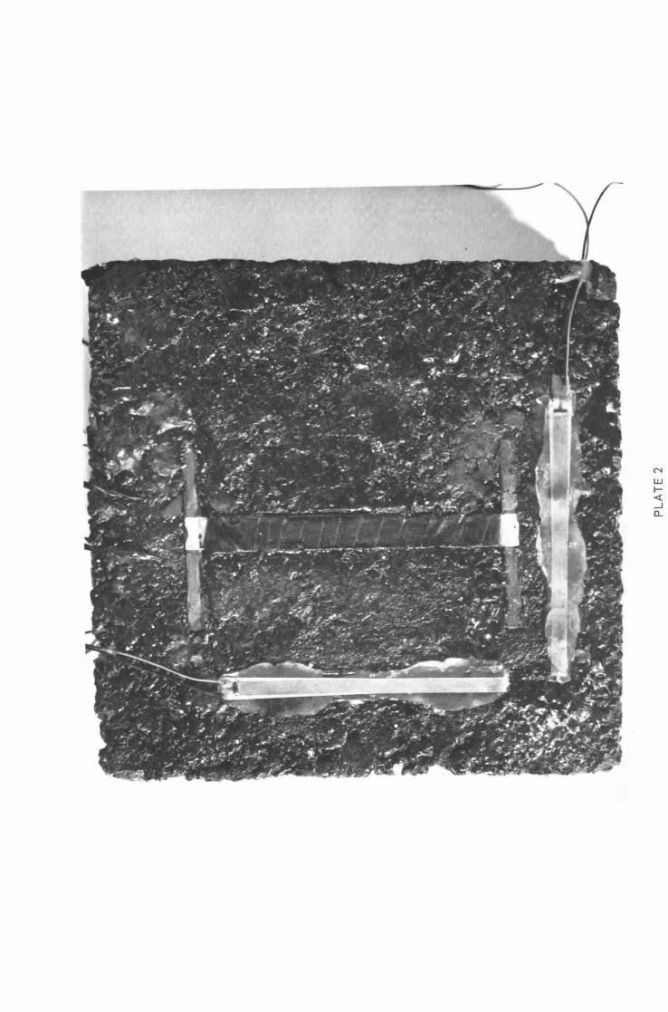
The second design consists of lOlmm resistive foil strain gauges cemented to a brickette of the base material made in the laboratory. The brickette of dimensions 203mm x 203mm x 63mm, is placed in the
4
desired position.on the.sub-base and forms a homogeneous, m a s s with the basematerial during laying and compacting of the base,~ Unfortunately due to.its thickness it.is unsuitable in the surface,layers. Plate 2 shows.the underside of a brickette into which an aluminium strip gauge was.cast during manufacture; the two resistive foil.gauges were cemented in position later. It is intended to compare the performance of the two gauge designsduring the .experiment.
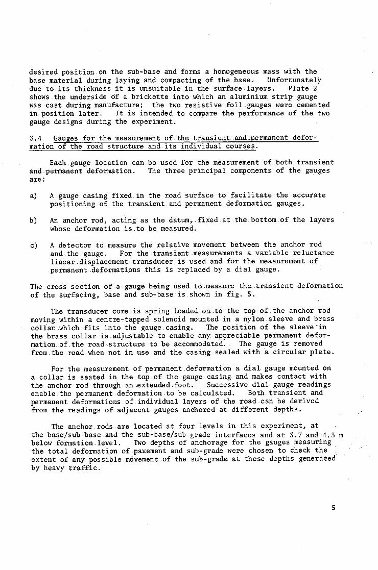
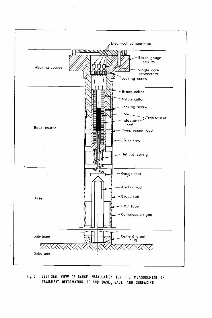
3.4 Gauges for the measurement of the transient, and.permanent defor- mation of the road structure and its individual courses.
Each,gauge location can be used for the measurement of both transient and,permanent deformation. The three principal components of the gauges are :
a)
b)
A.gauge casing fixed.in the road surface to facilitate the.accurate positioning of the trans_ientand permanent deformation gauges.
An anchor rod, acting as the datum,.fixed.at:the bottom of the layers whose deformation is to be measured.
c) A detector to measure the relative movement between the anchor rod and-the gauge. For the transient.measurements a vsmiable reluctance linear.displacement transducer.is used-and for the measurement of permanent.deformaZions this is replaced by a dial gauge.
The cross section of.a gauge being used to.measmre the.transient deformation of the surfacing, base and sub-base'is shown in fig. 5.
The transducer core is spring loaded on.to the,top of.the anchor rod moving-within a centre~tapped solenoid mounted in a nylon.sleeve and brass collar which fits into the gauge.casing. The position of the sleeve~in the brass;collar is.adjustable to enable an Z appreciable permanent defor- mation.of_the road-.structuze to be accommodated.. The gauge is removed from,the.road.when not in use and the casing sealed with a.circular plate.
For the measurement of permanent deformationa..dial gauge mounted on a collar is seated in the top.of the gauge casing and.makes contact with theanchor rod through an. extended.foot. Successive dial. gaugereadings enable the permanent deformation to be calculated. Both. transient and permanent deformations of individual layers of the road.can be.derived from the readings of adjacent gauges anchored.at different depths.
The anchor rods _are located at four levels in this .experiment, at the base/sub-base.and the sub-base/sub-grade interfaces and at 3.7 and 4.3 m below formation.level. Two depths of anchorage for the gauges measuring the total deformation.ofpavement and sub-grade were chosen to check the extent of any possible m6vement,of the sub-grade at these depths generated by heavytraffic.
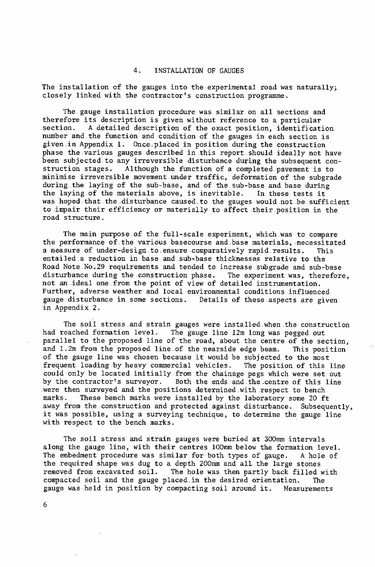
4. INSTALLATION OF GAUGES
The i n s t a l l a t i o n o f t h e gauges i n t o t h e e x p e r i m e n t a l road. was n a t u r a l l y ; closely linkedwith the contractor's construction programme.
The gauge i n s t a l l a t i o n p r o c e d u r e was s i m i l a r on a l l s e c t i o n s and t h e r e f o r e i t s d e s c r i p t i o n i s g i v e n w i t h o u t r e f e r e n c e t o a p a r t i c u l a r
s e c t i o n . A d e t a i l e d d e s c r i p t i o n o f t h e e x a c t p o s i t i o n , i d e n t i f i c a t i o n number a n d t h e f u n c t i o n and c o n d i t i o n o f t h e gauges i n reach s e c t i o n i s g i v e n i n A p p e n d i x 1. O n c e . p l a c e d i n p o s i t i o n d u r i n g t h e c o n s t r u c t i o n p h a s e t h e v a r i o u s gauges d e s c r i b e d i n t h i s r e p o r t . s h o u l d i d e a l l y n o t have b e e n s u b j e c t e d t o a n y i r r e v e r s i b l e d i s t u r b a n c e d u r i n g t h e s u b s e q u e n t con- s t r u c t i o n s t a g e s . A l t h o u g h t h e f u n c t i o n o f a c o m p l e t e d p a v e m e n t i s t o m i n i m i s e i r r e v e r s i b l e m o v e m e n t . u n d e r t r a f f i c , d e f o r m a t i o n o f t h e s u b g r a d e d u r i n g t h e l a y i n g o f t h e s u b - b a s e , and o f t h e s u b - b a s e and b a s e d u r i n g t h e l a y i n g o f t h e m a t e r i a l s above , i s i n e v i t a b l e . In t h e s e t e s t s i t was hoped t h a t the d i s t u r b a n c e c a u s e d t o t he gauges w o u l d n o t be s u f f i c i e n t to impair their efficiency or materially to affecttheir.position in the road structure.
The main purpose:o£ the full-scale experiment, which.was to compare the performance of_the various basecourse and..base materials, necessitated a .measure of under-design.to.ensure.comparativelyrapid.results. This entailed a reduction in base and.sub,base thicknesses relative to the Road Note No.29 requirements and tended to increase subgrade and sub-base disturbance during the .construction phase. The experiment was, therefore, not an.ideal.one.from the point of view of detailed instrumentation. Further, adverse Weather and local environmentalconditions influenced gaugedisturbance in some sections. Details of these aspects are given in Appendix 2.
The s o i l s t r e s s and s t r a i n gauges were i n s t a l l e d w h e n t h e c o n s t r u c t i o n had r e a c h e d f o r m a t i o n l e v e l . The gauge l i n e 12m l o n g was pegged o u t p a r a l l e l t o t h e p r o p o s e d l i n e o f t h e r o a d , abou t t h e c e n t r e o f t h e s e c t i o n , and 1.2m f rom t h e p r o p o s e d l i n e o f t h e n e a r s i d e edge beam. Th i s p o s i t i o n o f t h e g a u g e l i n e was c h o s e n b e c a u s e i t would b e s u b j e c t e d to t h e most
f r e q u e n t l o a d i n g b y h e a v y c o m m e r c i a l v e h i c l e s . The p o s i t i o n o f t h i s l i n e c o u l d o n l y be l o c a t e d i n i t i a l l y f rom t h e c h a i n a g e pegs which were s e t ou t by t h e c o n t r a c t o r ' s s u r v e y o r . Both the ends and t h e - c e n t r e o f t h i s l i n e
w e r e t h e n s u r v e y e d and t h e p o s i t i o n s d e t e r m i n e d w i t h r e s p e c t t o bench marks . These b e n c h marks were i n s t a l l e d by t h e l a b o r a t o r y some 20 f t away f rom t h e c o n s t r u c t i o n and p r o t e c t e d a g a i n s t d i s t u r b a n c e . S u b s e q u e n t l y , i t was p o s s i b l e , u s i n g a s u r v e y i n g t e c h n i q u e , t o d e t e r m i n e t h e gauge l i n e w i t h r e s p e c t t o t h e bench marks .
The s o i l s t r e s s and s t r a i n gauges were b u r i e d a t 300mm i n t e r v a l s a l o n g t h e gauge l i n e , w i t h t h e i r c e n t r e s lOOmmbelow t h e f o r m a t i o n l e v e l . The embedment p r o c e d u r e was s i m i l a r f o r b o t h t y p e s o f gauge . A h o l e o f t h e r e q u i r e d shape was dug t o a d e p t h 200mm and a l l t h e l a r g e s t o n e s removed f rom e x c a v a t e d s o i l . The h o l e was t h e n p a r t l y back f i l l e d w i t h c o m p a c t e d s o i l and t h e gauge p l a c e d . i n t h e d e s i r e d o r i e n t a t i o n . The gauge was h e l d i n p o s i t i o n by c o m p a c t i n g s o i l a r o u n d i t . Measurements
6
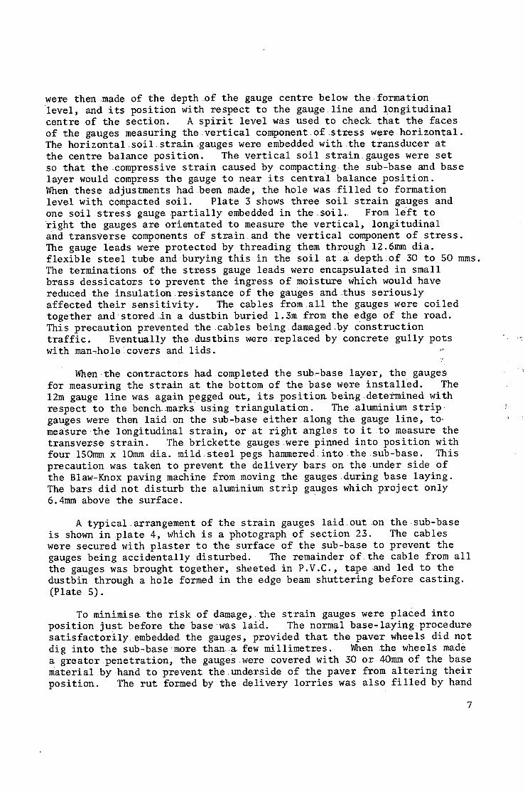
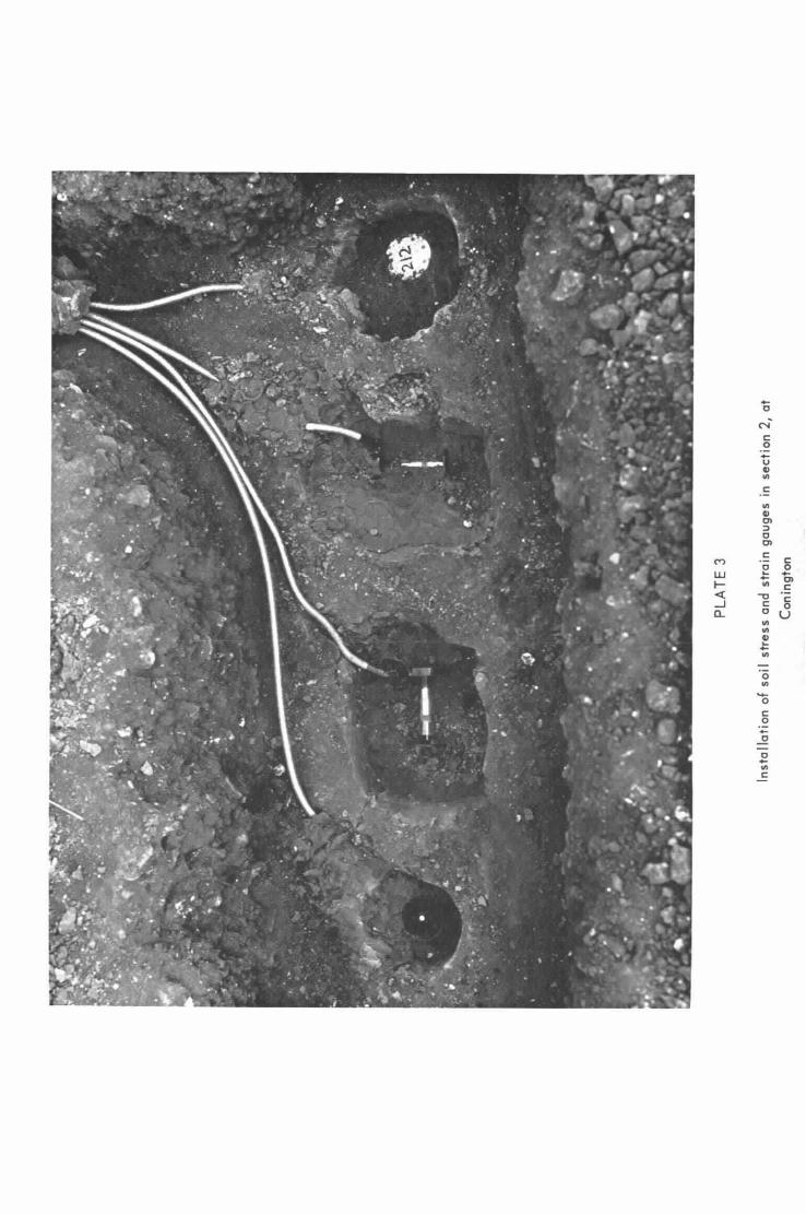
were then ,made of the depthof the gauge centre below the formation level, and its position with respect to the gauge line and longitudinal centre of the section. A spirit level was used to check that the faces of the gauges measuring the vertical component of stress were horizontal. The horizontal soil strain gauges were embedded with the transducer at the centre balance position. The vertical soil straingauges were set so that the compressive strain caused by compacting the sub-base and base layer would compress the gauge to near its central balance position. Whenthese adjustments had been made, the hole was filled to formation level with compacted soil. Plate 3 shows three soil strain gauges and one soil stress gauge partially embedded in the soil.. From left to right the gauges are orientated to measure the vertical, longitudinal and transverse components of strain.and the vertical component of stress. The gauge leads were protected by threading them through 12.6mm dia. flexible steel tube and burying this in the soil at a depth:of 30 to 50 mms. The terminations of the stress gauge leads were encapsulated in small brass dessicators to prevent the ingress of moisture which would have reduced the insulation.resistance of the gauges and thus seriously affected their sensitivity. The cables from all the gauges were coiled together and~stored i~ a dustbin buried 1.3m from the edge of the road. This precaution prevented the cables beingdamagedoby construction traffic. Eventually the dustbins were replaced by concrete gully pots with man~holelcovers and lids. ~
When.the contractors had completed the sub-base layer, the gauges for measuring the strain at the bottom of the basewere installed. The 12m gauge line was again pegged out, its position being determined with respect to the benchmarks using triangulation. Thealuminium strip. gauges were then laid on the sub-base either along the gauge line, to, measure the longitudinal strain, or at right angles to.it to measure the transverse strain. The brickette gauges.were pinned into position with four 150mm x iOmm dia. mild.steel pegs hammered into the.sub-base. This precaution was. taken to prevent the delivery bars on theunder side of the Blaw-Knox paving machine frommoving the gauges during base laying. The bars did not disturb the aluminium strip gauges which project only 6.4mm above the surface.
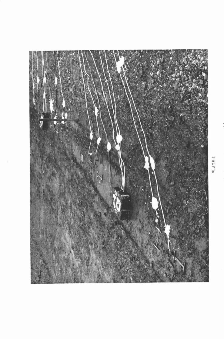
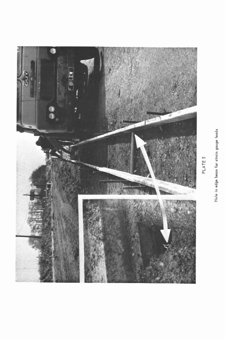
A typical.arrangement of the strain gauges laid:out on the-sub-base is shown in plate 4, which is a photograph of section.23. The cables were secured with plaster to the surface of the sub-base to prevent the gauges being accidentally disturbed. The remainder of the cable from all the gauges was brought together, sheeted in P.V.C., tape and led to the dustbin through a hole formed in the edge beam shuttering before casting. (Plate 5).
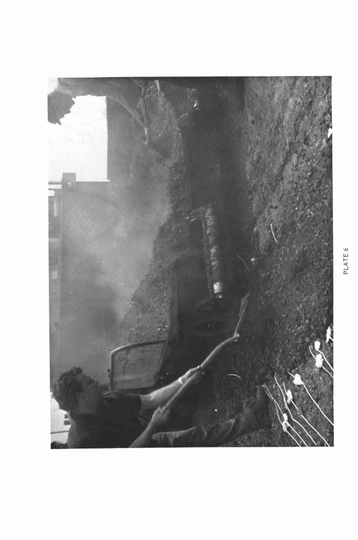
To minimise the risk of damage, the strain gauges were placed into position just before the base was laid. The normal base-laying procedure satisfactorilyembedded the gauges, provided that the paver wheels did not dig into the sub-base more ghana few millimetres. When the wheels made a greater penetration, the gauges.were covered with 30 or 40mm of the base material.by hand.to prevent the unde~side of the paver from altering their position.. The rut formed by the delivery lorries was also filled by hand
7
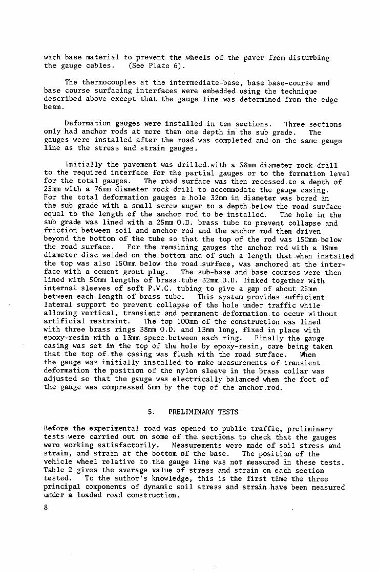
with base material to prevent the wheels of the paver from disturbing the gauge cables. (See Plate 6).
The thermocouples at the intermediate-base, basebase-course and base course surfacing interfaces were embeddedusing the technique described above except that the gauge line was determined from the edge beam.
Deformation gauges were installed in ten sections. Three sections only had anchor rods at more than one depth in the sub grade. The gauges were installed after the road was completed and on the same gauge line as the stress and strain gauges.
Initially the pavement was drilled.with a 38mm diameter rock drill to the required interface for the partial gauges or to the formation level for the total gauges. The road surface was then recessed,to a depth of 25mm with a 76mm diameter rock drill to accommodate the gauge casing. For the total deformation gauges ~ hole 32mm in diameter was bored in the sub grade with a small screw auger to a depth below the road surface equal to the length of the anchor rod to be installed. The hole in the sub grade was lined with a 2Smm O.D. brass tube to prevent collapse and friction between soil and anchor rod and the anchor rod then driven beyond the bottom of the tube so that the top of the rod was 150mm below the road surface. For the remaining gauges the anchor rod with a 19mm diameter disc welded on the bottom and of such a length that when installed the top.was also 15Omm below the road surface, was anchored at the inter- face with a cement grout plug. The sub-base and base courses were then lined with SOmm lengths of brass tube 32mm,O.D. linked together with internal sleeves of soft P.V.C. tubing to give a gap of about 2Smm between each length of brass tube. This system provides sufficient lateral support to prevent collapse of the hole under traffic while allowing vertical, transient and permanent deformation to occur without artificial restraint. The top lOOmm of the construction was lined with three brass rings 38mm O.D. and 13mm long, fixed in place with epoxy-resin with a 13mm space between each ring. Finally the gauge casing was set in the top of the hole by epoxy-resin, care being taken that the top of.the casing was flush with the road surface. When the gauge was initially installed to make measurements of transient deformation the position of the nylon sleeve in the,brass collar was adjusted so that the gauge was electrically balanced when the foot of the gauge was compressed 5mm by the top of the anchor rod.
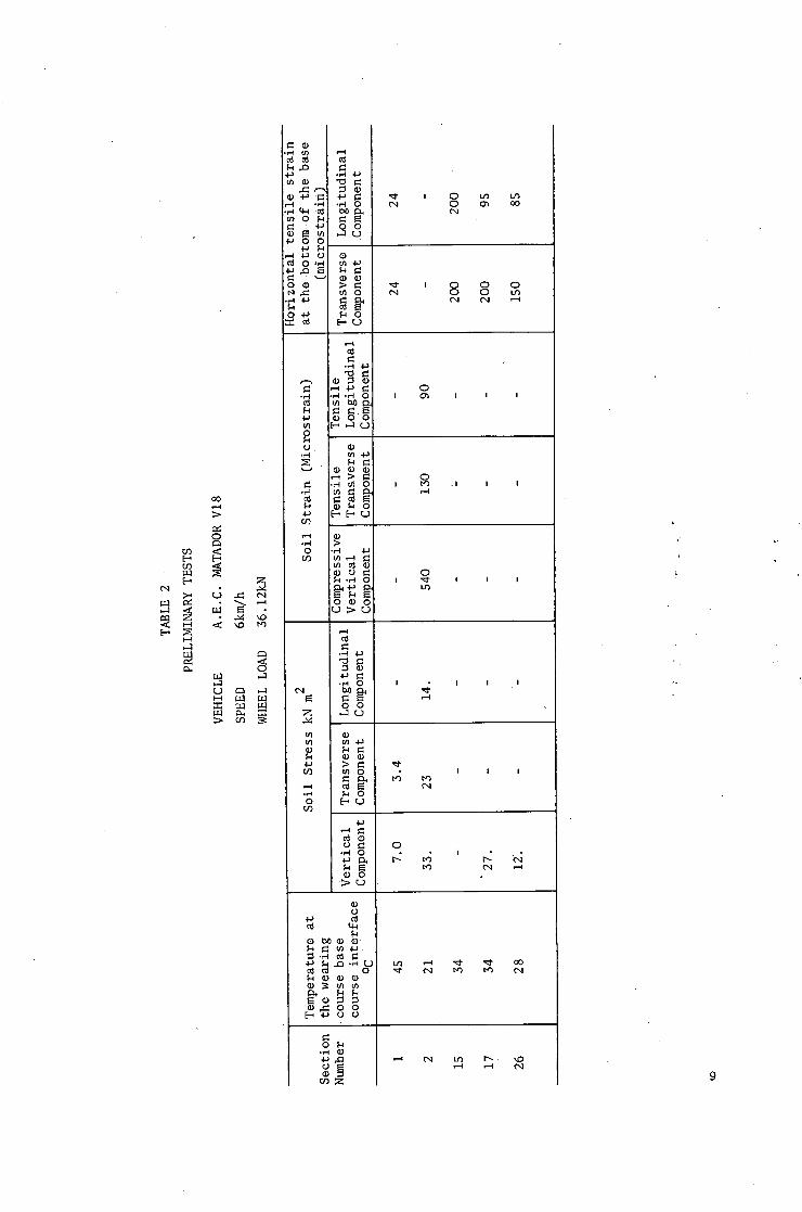
S. PRELIMINARY TESTS
Before the experimental roadwas opened to public traffic, preliminary tests:were carried out on some of.the sections to check that the gauges were working satisfactorily. Measurements were made of soil stress a~d strain, and strain at the bottom of the base. The position of the vehicle wheel relative to the gauge line was not measured in these tests. Table 2 gives the average value of stress and strain on each section tested. To the author's knowledge, this is the first time the three principal components of dynamic soil stress and strainhave been measured under a loaded road construction.
8
U-I ,.-1
[-..,
0o
0
E~
Z
~ . ~ .
e~ a l ,..a
r n e~ ~ ~ m N:
I 0 IJ') L/') 0 O~ oO
.
0 t ~ . . C
0 .1~
Z
0
,,l.a
¢) ,I~
o
0
0 0 0
• ,...4 .,"4 0
~ ~ o m ,..1 r j o
~ Q
.~ ~ o
0 .,-4 4-~
O
O t ~
O
.H O
O O
o
O
I
• ~ ~o O
(D O
~ ~ .~ . -o ~
~ , ~ o o
O•
r ~ z
c~ L~ D~ ~O
9
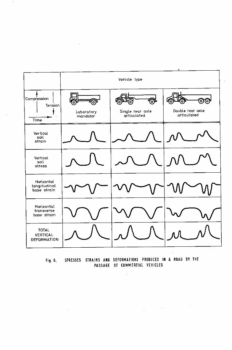
When the road was opened to public traffic, the dynamic soil stress and strain, the base strains and the vertical deformations generated by commercial vehicles were studied. Figure 6 shows the pulse shapes from some of the gauges embedded in section 20. The vertical components of soil stress and strain were both compressive and have values up to 35kN/m 2 and 500 microstrain. The longitudinal horizontal strain at the bottom of the base was initially compressive as the wheel approached the gauge and then became tensile as the wheel passed over the gauge (reaching a maximum Of up to I00 microstrain) and finally became compressive again as the wheel moved away. The transverse horizontal strain at the bottom of the base was tensile with a value up to i00 microstrain whe~ the wheel passed directly over the gauge. The total vertical deformation of the whole road structure reached values as high as 1 mm. The values quoted above for section 20 are dependent on wheel load, vehicle speed and construction temperature.
6. PROPOSEDTEST PROGRAMME
In addition to the normalmethod of assessing performance by measuring changes in the lateralprofile of the road by levelling under known traffic the performance of the experimentalsections will be studied by measuring the dynamic stresses, strains and transient deformation generated under a standard moving wheel load. The test vehicle will bathe Laboratory's A.E.C. Mandator, V27, which has either single or dual~wheel facilities on its rear axle. Comparative tests will be performed at six-monthly intervals, in the spring and the autumn, when the temperatures of the road construction are reasonably constant and of similar magnitude. This precaution is necessary because with bituminous materials, the stresses and strains generated in the Construction by the test vehicle are dependent on the road temperature. The viscoelastic properties of the construction materials also make it necessary for the comparative tests to be made at the same vehicle speed.
It is intended to make measurements during the summer months to obtain more information on the effect of temperature of the construction materials on the magnitude of the dynamic stresses and strains. The effect of altering the vehicle parameters, wheel configuration, wheel load and speed, will be examined on the sections with full instrumentation. Measurements will also be made of the stresses and strains generated by normal commercial traffic.
7. ACKNOWLEDGEMENTS
The Laboratory wishes to acknowledge the very willing assistance of the Huntingdonshire and Peterborough County Council, the Divisional Road Engineer and the Contractor (Messrs. A. Monk ~ Co. Ltd..) in connection with this full-scale experiment.
The stress and strain gauges were developed and installed by the Structural Properties Section of the Laboratory (Dr. A.C. Whiffin, Section Leader).
I0
The Pavement Design Section (Mr; D. Croney, Section Leader) was responsible for the design and supervision of the full-scale experiment as a whole and for the design and installation of the deformation gauges.
The authors acknowledge the assistance given by A. Nagarkatti, R.A. Whitmarsh, M. Ryall, J.B. Steven and F.B. Fawcett with the installation of the gauges.
I.
.
.
.
.
.
8. REFERENCES
TROTT, J.J. and A.C. WHIFFIN. Measurement of the.axle loads of moving vehicles on Trunk Roads. RoadsandRoadConstruction, Voi.43 No.511, pp 209 - 214 July 1965.
JONES, R. and H.C. MAYHEW~ Thickness andquality of cemented surfacings and bases - Measuring by anon-destructive surface wave method; Civil Engineering 1965, 60 (705)
WHIFFIN, A~C. and S.A.H. MORRIS. The RRL piezoelectric gauge for measuring dynamic stresses under roads "The Engineer 1962".
MAYHEW, H.C. A gauge for measuring dynamicstresses in soil. To be published as a RoadResearch Laboratory Report.
POTTER, J.F. Gauge for the measurement of dynamic and long term strains in soil. Road Research Laboratory Report LR.251.
LISTER, N.W. and A.P. MAYO. A gauge for the measurement of transient and permanent deformations in road pavements. To be published as a Road Research Laboratory Report.
ii
Gauge Number
211
209
40N
18N
151
125
265
APPENDIX i
GAUGE LAYOUT.ON THE INSTRUMENTED SECTIONS
TABLE i
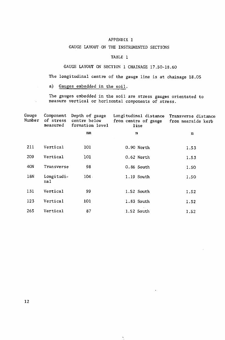
GAUGE LAYOUT ON SECTION i CHAINAGE 17.50-18.60
The longitudinal centre of the gauge line is at chainage 18.05
a) Gauges embedded in the soil.
The gauges embedded in the soil are stress gauges orientated to measure vertical or horizontalcomponents of stress.
Component of stress measured
Depth of gauge centre below formation level
mm
Longitudinal distance from centre of gauge
i ine
m
Transve r se d i s t a n c e from n e a r s i d e kerb
m
Vertical
Vertical
Transverse
Longitudi- nal
Vertical
Vertical
Vertical
101
i01
98
104-
99
101
87
0.90 North
0.62 North
0.86 South
1.19 South
1.52 South
1.83 South
1.52 South
1.53
i .53
1.50
1.50
1.52
1.52
1.52
12
Number
8
i00
4
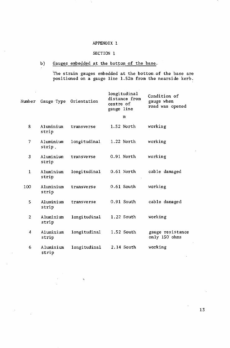
b)
APPENDIX 1
SECTION i
Gauges embedded at the bottom of the basel
~The strain gauges embedded at the bottom of the base are positioned on a gauge line 1.52m from the nearside kerb.
GaugeType
Aluminium strip
Aluminium strip
Aluminlum strip
Aluminlum strip
Alumlnlum strip
Aluminium strlp
Aluminium strlp
Aluminium strip
Aluminium strip
Orientation
transverse
1 ongi tudinal
transverse
longitudinal
transverse
transverse
i on gi tudi nal.
longitudinal
longitudinal
longi tudin a 1 distance from centre of gauge line
m
1.52 North
1.22 North
0.91 North
0.61 North
0.61 South
0.91 South
1.22 South
1.52 South
2.14 South
Condition of gauge when road was opened
working
working
working
cable damaged
working
cable damaged
working
gauge resistance only 150 ohms
working
13
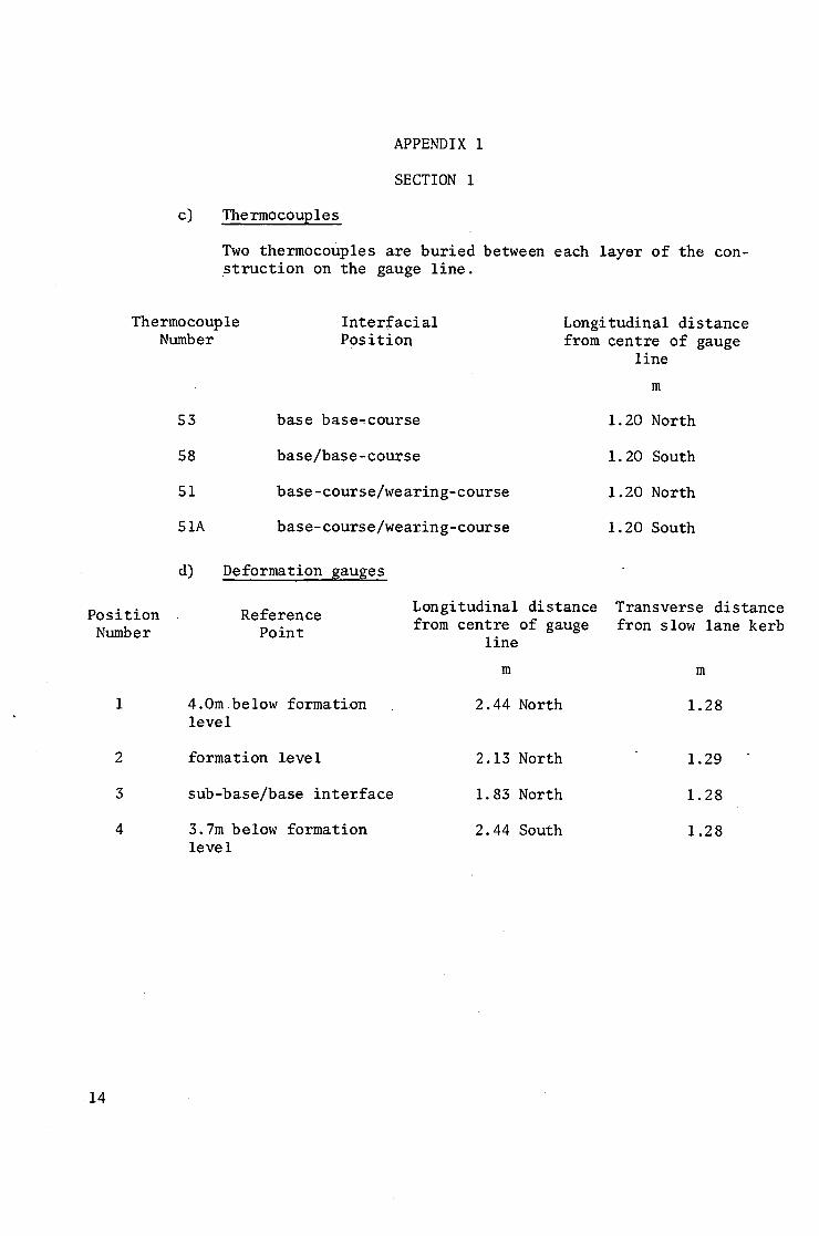
c)
APPENDIX 1
SECTION 1
Position Number
Thermocouples
2
3
4
Two themmocouples are buried between each layer of the con- struction on the gauge line.
Thermocouple Number
Interfacial Position
53
58
51
SIA
d) Deformation gauges
base base.course
base/base-course
base-course/wearing-course
base-course/wearing-course
Longitudinal distance from centre of gauge
line
m
i. 20 North
i. 20 South
i. 20 North
i. 20 South
Reference Point
4.0m below formation leve I
formation level
sub-base/base interface
3.7m below formation le ve I
Longitudinal distance Transverse distance from centre of gauge fron slow lane kerb
line
m m
2.44 North 1.28
2.13 North 1.29
1.83 North 1.28
2.44 South 1.28
14
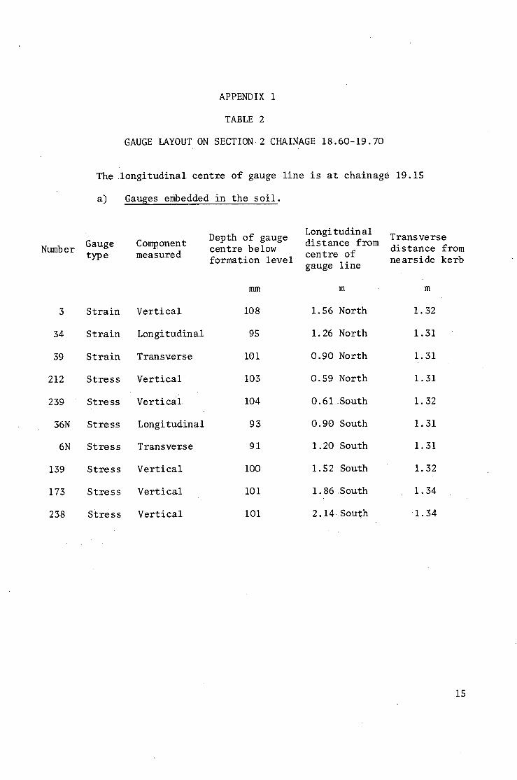
Numb e r
3
34
39
212
239
36N
6N
139
173
238
APPENDIX I
TABLE 2
GAUGE LAYOUT ON SECTION.2 CHAINAGE 18..60.19.70
The longitudinal centre of gauge line is at chainage 19.15
a) Gauges embedded in the soil.
Gauge Component t y p e m e a s u r e d
Strain
Strain
Strain
Stress
Stress
Stress
Stress
Stress
Stress
Stress
Vertical
Longitudinal
Transverse
Vertical
Vertical
Longitudinal
Transverse
Vertical
Vertical
Vertical
Longi tudin al Depth of gauge distance from centre below
centre of formation level
gauge line
mm m
108 1.56 North
95 1.26 North
I01 0.90 North
103 0.59 North
104 0.61 South
93 0.90 South
91 1.20 South
I00 1.52 South
i01 1.86 South
i01 2.14 South
T r a n s ve r s e d i s t a n c e f rom n e a r s i d e k e r b
m
1.32
i .31
1.31
1.31
i . 32
1.31
1.31
1.2;2
i . 34
1.34
15
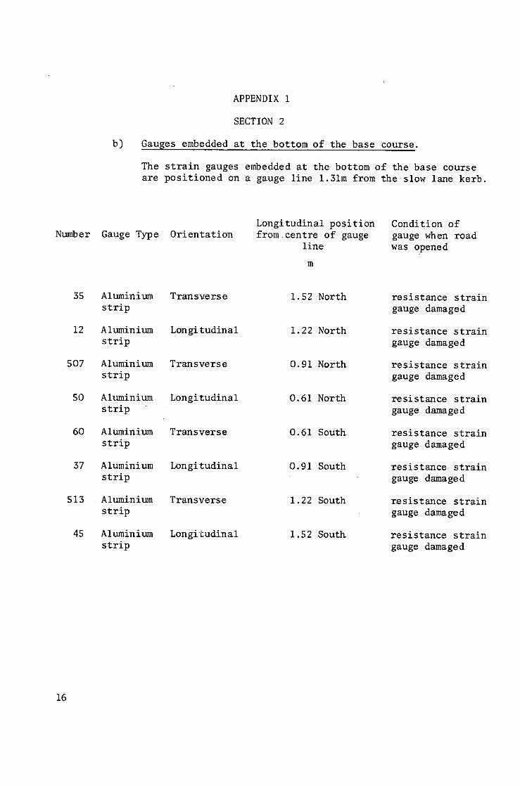
b)
APPENDIX i
SECTION 2
Gauges embedded at the bottom of the base course.
The strain gauges embedded at the bottom of the base course are positioned on a gauge line 1.31m from the slow lane kerb.
Number Gauge Type Orientation
35
12
507
50
60
37
513
45
Aluminlum strip
Alumlnlum strip
Aluminium strip
Alumlnlum strip
Aluminium strip
Aluminium strip
Aluminlum strip
Aluminium strip
Tran sverse
Lon gi tudinal
Transverse
Longitudinal
Transverse
Lon gi tudina i
Transverse
Longitudinal
Longitudinal position from centre of gauge
line
m
1.52 North
1.22 North
0.91 North
0.61 North
0 .61 S o u t h
0.91South
1.22 South
1.52 South
Condition of gauge when road was opened
resistance strain gauge damaged
r e s i s t a n c e s t r a i n gauge damaged
r e s i s t a n c e s t r a i n gauge damaged
r e s i s t a n c e s t r a i n gauge damaged
r e s i s t a n c e s t r a i n gauge damaged
r e s i s t a n c e strain gauge damaged
resistance strain gauge damaged
resistance strain gauge damaged
16
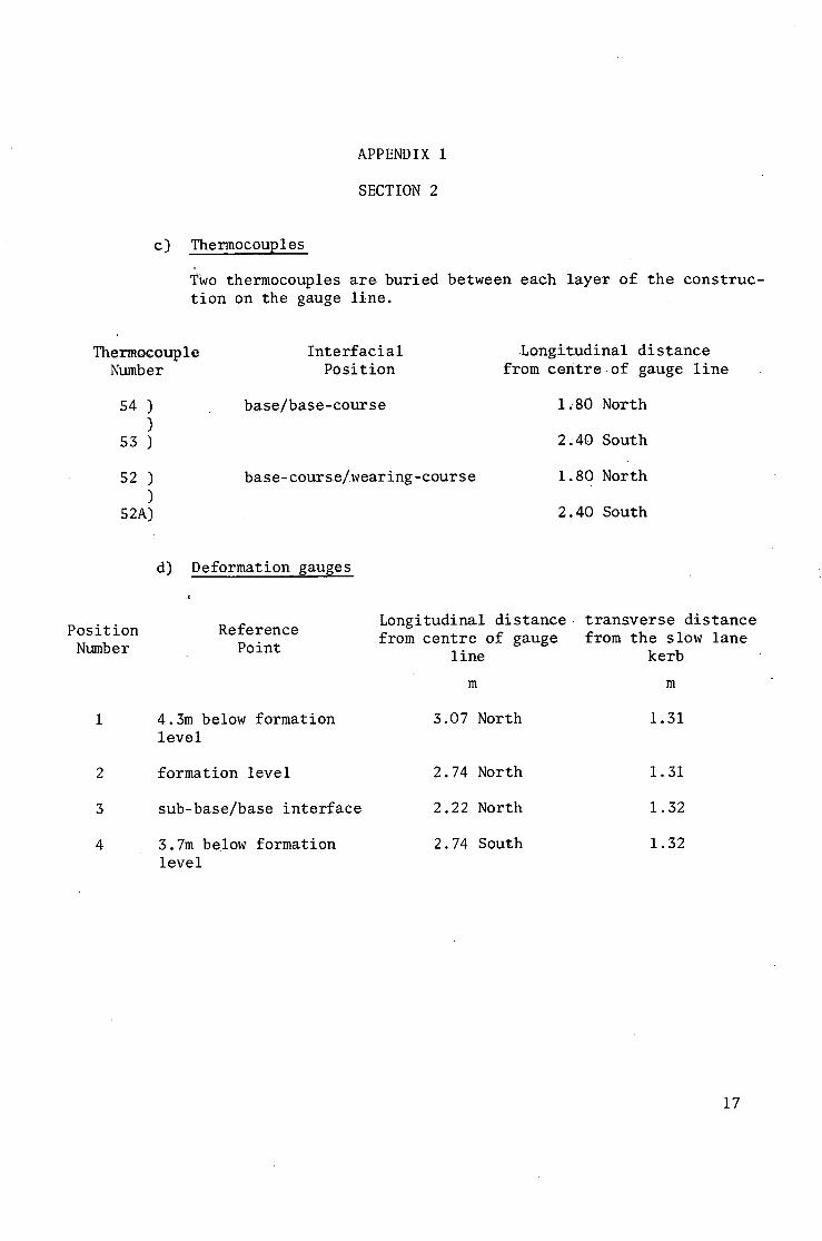
APPENDIX 1
SECTION 2
c) Thermocouples
Two t h e r m o c o u p l e s a r e b u r i e d b e t w e e n each l a y e r o f t h e c o n s t r u c - t i o n on t h e gauge l i n e .
Thermocouple Numb er
54 ) )
53 )
52 ) )
52A)
Interfacial Position
b a s e / b a s e - c o u r s e
base-course/wearing-course
.Longitudinal distance from centre of gauge line
1,80 North
2.40 South
1.80 North
2.40 South
Position Numb e r
2
3
4
d) Deformation gauges
,L
Reference Point
4.3m below formation level
formation level
sub-base/base interface
3.7m below formation level
Longitudinal distance~ transverse distance from centre of gauge from the slow lane
line kerb
m m
3.07 North 1.31
2.74 North 1.31
2.22 North 1.32
2.74 South 1.32
17
Number
APPENDIX 1
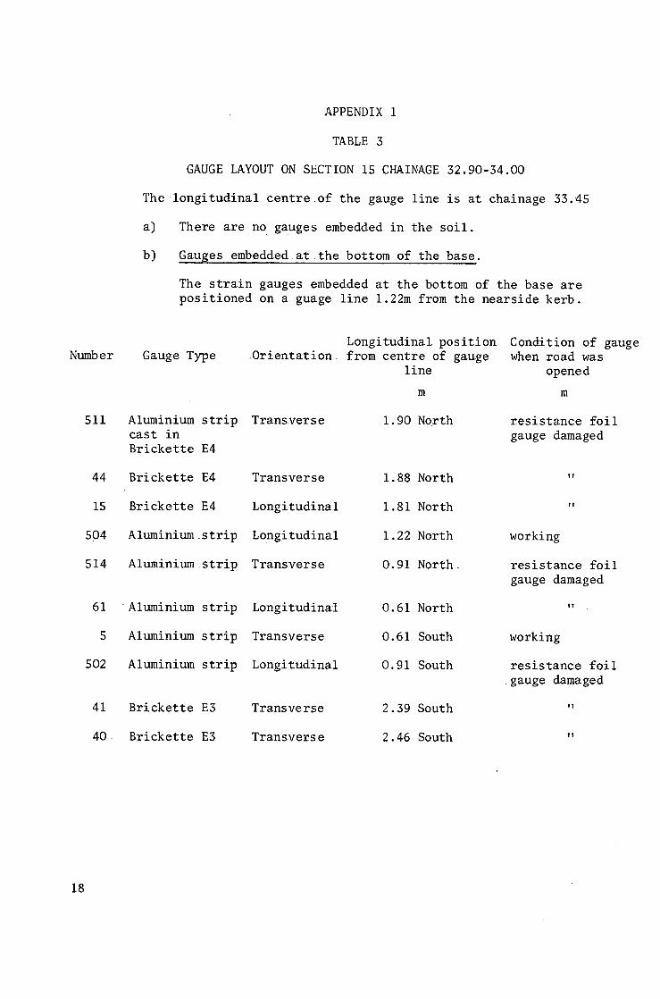
TABLE 3
GAUGE LAYOUT ON SECTION iS CHAINAGE 32.90-34.00
The longitudinal centre of the gauge line is at chainage 33.45
a) There are no gauges embedded in the soil.
b) Gauges embedded at the bottom of the base.
The strain gauges embedded at the bottom of the base are positioned on aguage line 1.22m from the nearside kerb.
Gauge Type
511 Aluminium strip cast in Brickette E4
44 Brickette E4
15 Brickette E4
504 Aluminiumstrip
514 Aluminiumstrip
61 Aluminium strip
5 Aluminiumstrip
502 Aluminium strip
41 Brickette E3
40 Brickette E3
Longitudinal position Condition of gauge ..Orientation. from centre of gauge when road was
line opened
m m
Transverse 1.90 North resistance foil gauge damaged
Transverse 1.88 North "
Longitudinal 1.81 North "
Longitudinal 1.22 North working
Transverse 0.91 North resistance foil
Longitudinal
Transver se
Long i tud ina l
Transverse
Transve r se
0.61 North
0.61 South
0.91 South
2.39 South
2.46 South
gauge damaged
ly
working
resistance foil gauge damaged
T!
18
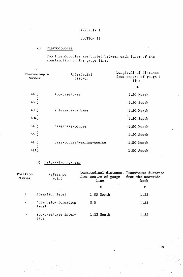
APPENDIX 1
SECTION 15
c) Thermocouples
Two thermocouples are buriedbetween each layer of the constructionon the gauge line.
Thermocouple Number
44 ) )
43 )
40 ) )
40A)
54 ) )
56 )
41 ) )
41A)
Interfacial Position
sub-base/base
intermediate base
base/base-course
base-course/wearing-course
~Longitudinal distance from centre of gauge 1
line
m
1.50 North
1.50 South
1.50 North
1.50 South
1.50 North
1.50 South
1.50 North
1.50 South
Pos i ti on Number
1
2
3
d) Deformation gauges
Reference Point
formation level
4.3m below formation level
sub-base/base inter- face
Longitudinal distance• Transverse distance from centre of gauge from the nearside
line kerb
m m
1.85 North 1.22
O.O 1.22
1.83 South 1.22
19
• ~ Y
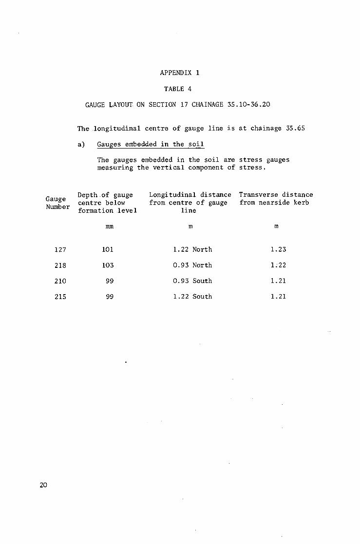
APPENDIX 1
TABLE 4
GAUGE LAYOUT ON SECTION 17 CHAINAGE 35.10-36.20
The longitudinal centre of gauge line is at chainage 35.65
a) Gauges embedded in the soil
The gauges embedded in the soil are stress gauges measuring the vertical component of stress.
Gauge Number
Depth of gauge centre below formation level
mm
Longitudinal distance from centre of gauge
line
m
Transverse distance from nearside kerb
m
127
218
210
215
i01
103
99
99
1.22 North
0.93 North
0.93 South
1.22 South
1.23
I;22
1.21
1.21
20
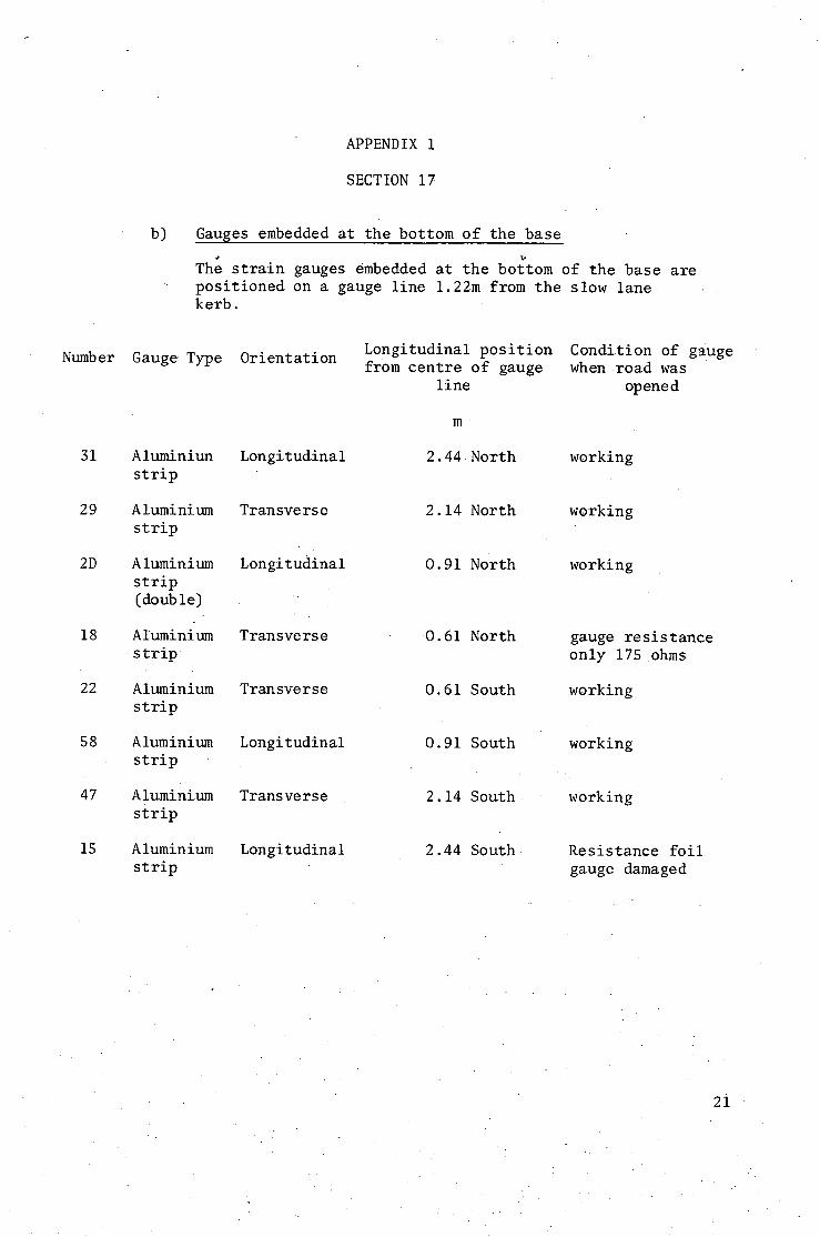
APPENDIX 1
SECTION 17
b) Gauges embedded at the bottom of the base
The strain gauges embedded at the bottom of the base are positioned on a gauge line 1.22m from the slow lane kerb.
Number Gauge Type
31 A luminiun strip
29 Aluminium strip
2D Aluminium strip (double)
18 Aluminium strip •
22 Aluminium strip
58 Aluminium strip
47 Aluminium strip
15 Aluminium strip
Orientation
Longitudinal
Tr an sve rs e
Longitudinal
Transverse
Transverse
Longitudinal
Transverse
Longitudinal
Longitudinal position Condition of g~uge from centre of gauge when road was
line
m
2.44 North
opened
working
2.14 North working
0.91 North
0.61 North
working
0.61 South
gauge resistance only 175 ohms
working
0.91 South working
2.14 South working
2.44 South Resistance foil gauge damaged
1
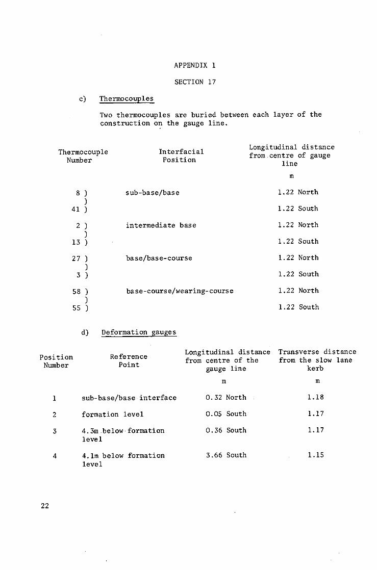
c)
APPENDIX 1
SECTION 17
Thermocouples
Two thermocouples are buried between each layer of the construction on the gauge line.
Thermocouple Number
8) )
41 )
2) )
13 )
27 ) )
3 )
s8 ) )
55 )
Interfacial Position
sub -base /ba se
intermediate base
b a s e / b a s e - c o u r s e
b a s e - c o u r s e / w e a r i n g - c o u r s e
Longitudinal distance fromcentre of gauge
line
m
1.22 North
1.22 South
1.22 North
1.22 South
1.22 North
1.22 South
1.22 North
1.22 South
Position Numb er
1
2
3
4
d) Deformation gauges
Reference Point
s u b - b a s e / b a s e . i n t e r f a c e
formation level
4.3m below formation level
4.1m below formation level
Longitudinal d i s t a n c e Transverse distance from c e n t r e of the from the slow lane
gauge l i ne kerb
m m
0.32 North 1.18
0.05 South 1.17
0.36 South 1.17
3.66 South 1.15
22
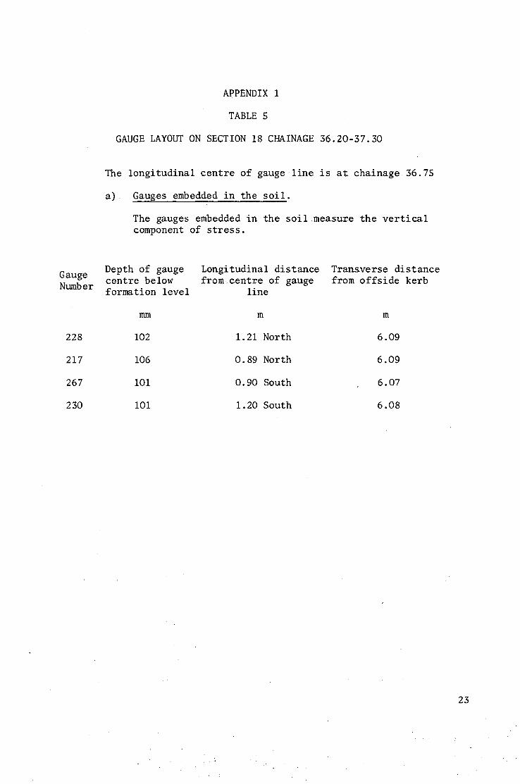
APPENDIX 1
TABLE 5
GAUGE LAYOUT ON SECTION 18 CHAINAGE 36.20-37.30
The longitudinal centre of gauge line is at chainage 36.75
a) Gauges embedded in the soil.
The gauges embedded in the soil measure the vertical component of stress.
G auge Number
228
217
267
230
Depth of gauge Longitudinal distance Transverse distance centre below from centre of gauge from offside kerb formation level line
mm m m
102 1.21 North 6.09
106 0.89 North 6.09
I01 0.90 South 6.07
i01 1.20 South 6.08
23
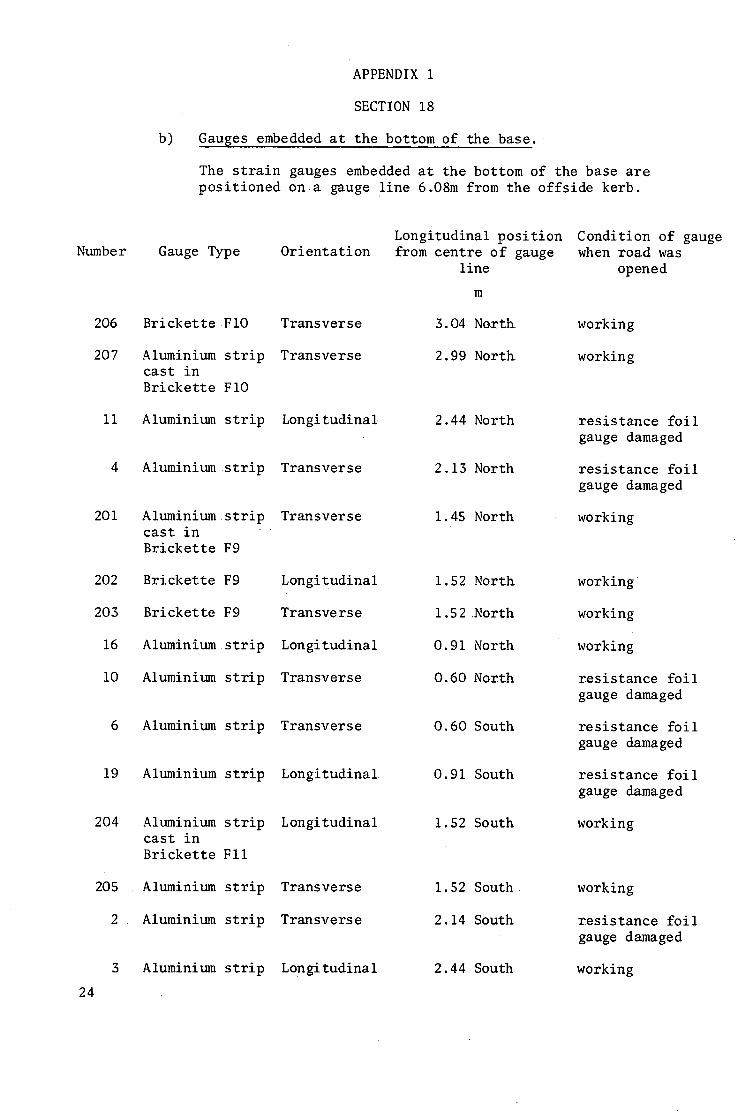
b)
APPENDIX i
SECTION 18
Gauges embedded at the bottom of the base.
The strain gauges embedded at the bottom of the base are positioned on a gauge line 6.08m from the offside kerb.
Number Gauge Type Orientation
206 BricketteFiO Transverse
207 Aluminium strip Transverse cast in Brickette FIO
ii Aluminium strip Longitudinal
4 Aluminium strip Transverse
201 Aluminiumstrip Transverse cast in Brickette F9
202 Brickette F9 Longitudinal
203 Brickette F9 Transverse
16 Aluminium strip Longitudinal
iO Aluminium strip Transverse
24
19
6 Aluminium strip
Aluminium strip
Aluminium strip cast in Brickette FII
204
205 A luminium strip
2 . Aluminium strip
3 Aluminium strip
Transverse
Longitudinal
Longitudinal
Transverse
Transverse
Longitudinal
Longitudinal position Condition of gauge from centre of gauge when road was
line opened
m
3.04 North
2.99 North
2.44 North
working
working
2.13 North
1.45 North
1.52 North
1.52North
0.91 North
0.60 North
r e s i s t a n c e f o i l gauge damaged
resistance foil gauge damaged
working
0.60 South
0.91 South
i. 52 South
working
working
working
resistance foil gauge damaged
resistance foil gauge damaged
resistance foil gauge damaged
working
1.52 South
2.14 South
2.44South
working
resistance foil gauge damaged
working
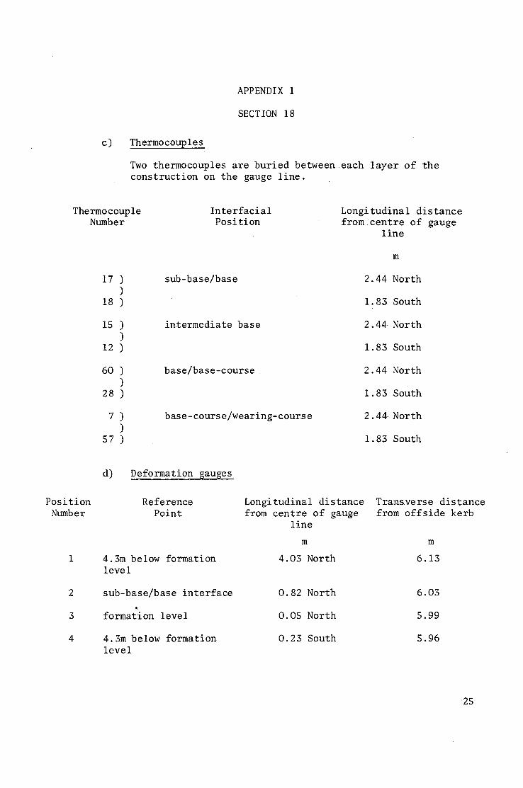
APPENDIX 1
SECTION 18
c) Thermocoup le s
Two t h e r m o c o u p l e s a r e b u r i e d b e t w e e n e a c h l a y e r o f t h e c o n s t r u c t i o n on t h e gauge l i n e .
The rmo coup le Number
i7 ) )
18 )
15 ) )
12 )
60 ) )
28 )
7 ) )
5 7 )
Interfacial Position
s u b - b a s e / b a s e
intermediate base
b a s e / b a s e - c o u r s e
b a s e - c o u r s e / w e a r i n g - c o u r s e
Longitudinal distance from centre of gauge
line
m
2.44 North
1.83 South
2.44 North
1.83 South
2.44 North
1.83 South
2.44 North
1.83 South
Position Number
d) Deformation gauges
Reference Point
4.3m below formation level
sub-base/base interface
formation level
4.3m below formation level
Longitudinal distance from centre of gauge
line
m
4.03 North
0.82 North
0.05 North
0.23 South
Transverse distance from offside kerb
m
6.13
6.03
5.99
5.96
25
Gauge Number
243
240
427
263
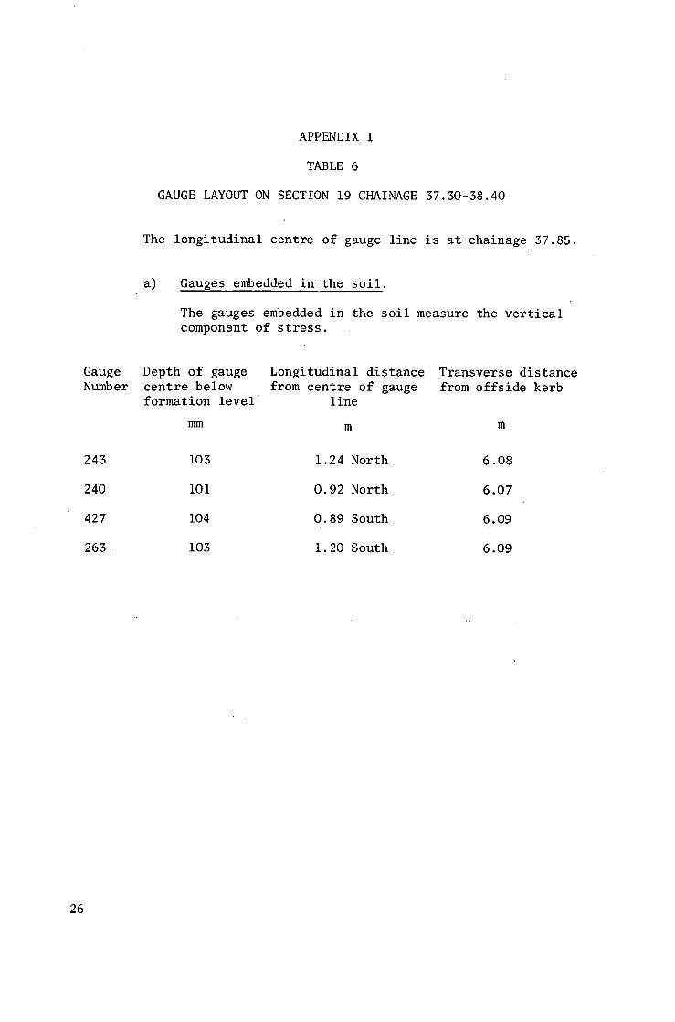
APPENDIX i
TABLE 6
GAUGE LAYOUT ON SECTION 19 CHAINAGE 37.30-38.40
The longitudinal centre of gauge line is at chainage 37.85.
a) Gauges embedded in the soil.
The g a u g e s embedded i n t h e s o i l m e a s u r e t h e v e r t i c a l c o m p o n e n t o f s t r e s s .
Depth of gauge Longitudinal distance Transverse distance centre below from centre of gauge from offside kerb formation level line
mm m m
103 1.24 North 6.08
IO1 0.92 North 6.07
104 0.89 South 6.09
103 1.20 South 6.09
26
Numb e r
211
212
213
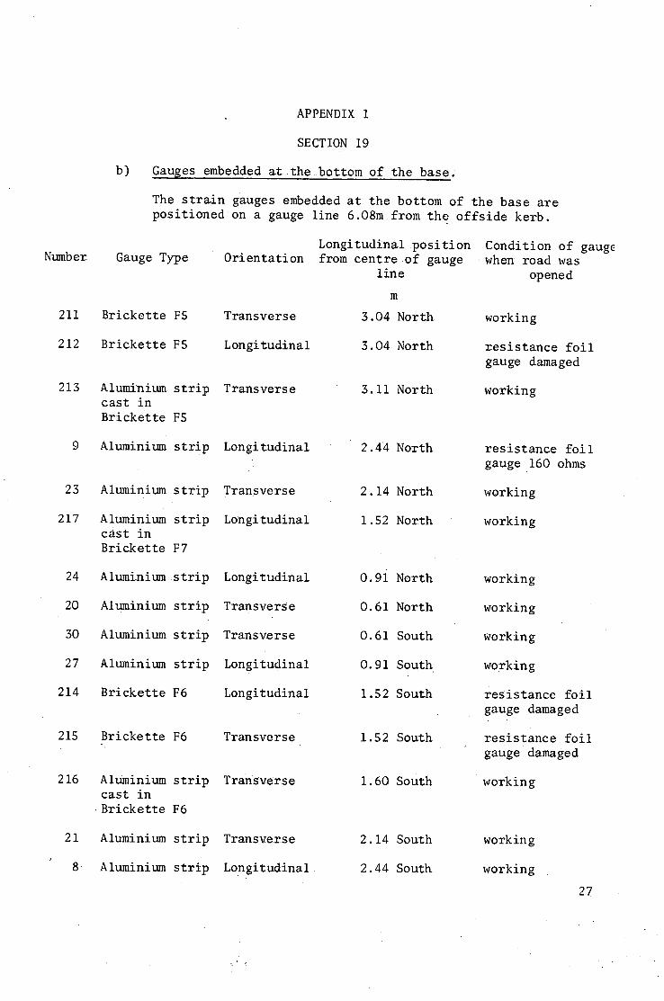
b)
APPENDIX 1
SECTION 19
Gauges embedded atthebottom of the base.
The strain gauges embedded at the bottom of the base are positioned on a gauge line 6.O8m from the offside kerb.
Gauge Type
Brickette F5
Brickette F5
Aluminium strip cast in Brickette F5
9 Aluminium strip
23 Aluminium strip
217 Aluminium strip cast in Brickette F7
24 Aluminiumstrip
20 Aluminium strip
30 Aluminium strip
27 Aluminium strip
214 Brickette F6
215 Brickette F6
216 Aluminium strip c a s t in • Brickette F6
Aluminium strip
Aluminium strip
Orientation
Transverse
L on gi tudina 1
Transverse
21
8
Longitudinalposition from centre of gauge
line
m
3.04 North
3.04 North
3.11 North
Condition of gauge when- road was
opened
working
resistance foil gauge damaged
working
Longitudinal
Transverse
Longitudinal
Longitudinal
Transverse
Transverse
Longitudinal
Longitudinal
2.44 North
2.14 North
1.52 North
0.9i North
0.61 North
O.61 South
0.91 South
1.52South
resistance foil gauge 160 ohms
working
working
Transverse
T r a n S v e r s e
1.52 South
I. 60 South
working
working
working
working
resistance foil gauge damaged
resistance.foil gaugedamaged
working
Transverse
Longitudinal
2.14 South
2.44 South
working
working
7
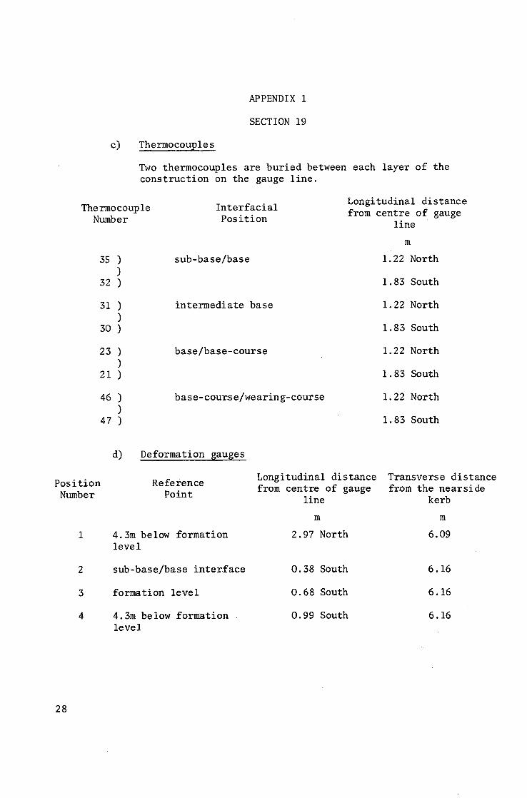
APPENDIX i
SECTION 19
c) Thermocouples
Two t h e r m o c o u p l e s a r e b u r i e d between each l a y e r o f the c o n s t r u c t i o n on the gauge l i n e .
The rmo coup le Number
35 ) )
32 )
Interfacial Position
s u b - b a s e / b a s e
Longitudinal distance from centre of gauge
line
m
1.22 North
1.83 South
31 ) )
30 )
intermediate base 1.22 North
1.83 South
23 ) )
2 1 )
b a s e / b a s e - c o u r s e 1.22 North
1.83 South
46 ) )
47 )
b a s e - c o u r s e / w e a r i n g - c o u r s e 1.22 North
1.83 South
Position Number
d) Deformation gauges
R e f e r e n c e Po in t
4.3m below formation level
sub-base/base interface
formation level
4.3m below formation level
Longitudinal distance Transverse distance from centre of gauge from the nearside
line kerb
m m
2.97 North 6.09
0.38 South 6.16
0.68 South 6.16
0.99 South 6.16
28
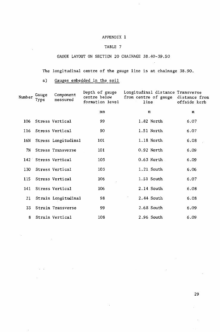
APPENDIX i
TABLE 7
GAUGE LAYOUT ON SECTION 20 CHAINAGE 38.40-39.50
The longitudinal centre of the gauge line is at chainage 38.90.
a) Gauges embedded in the soil
Number Gauge Component Typ6 measured
106 Stress Vertical
116 Stress Vertical
16N Stress Longitudinal
7N Stress Transverse
142 Stress Vertical
130 Stress Vertical
i15 Stress Vertical
141 Stress Vertical
21 Strain Longitudinal
53 Strain Transverse
8 Strain Vertical
Depth of gauge Longitudinal distance Transverse centre below from centre of gauge distance from formation level line offside kerb
mm m m
99 1.82 North 6.07
90 1.51 North 6.07
IO1 1.18 North 6.08
iO1 0.92 North 6.09
103 0.63 North 6.09
103 1.21 South 6.06
106 1.51 South 6.07
106 2.14 South 6.08
98 2.44 South 6.08
99 2.68 South 6.09
108 2.96 South 6.09
29
Number
46
41
407
403
43
38
37
40
36
373
393
397
59
7
28
25
30
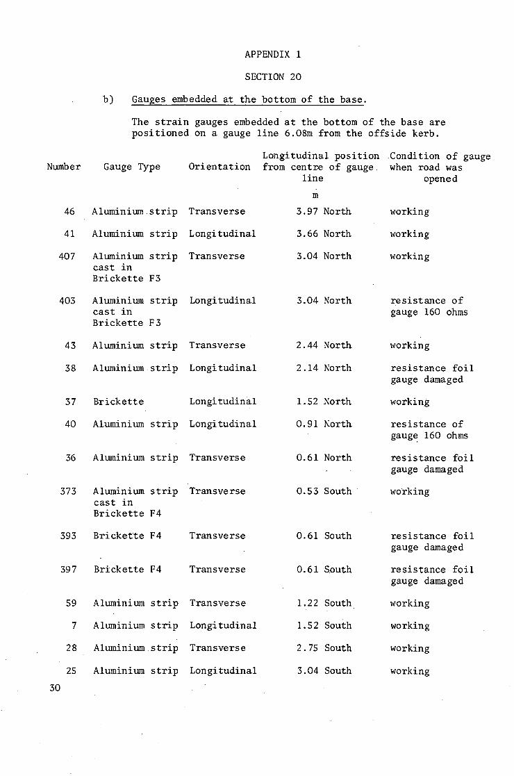
b)
APPENDIX I
SECTION 20
Gauges embedded at the bottom of the base.
The strain gauges embedded at the bottom of the base are positioned on a gauge line 6.08m from the offside kerb.
Longitudinal position Condition of gauge Gauge Type Orientation
Aluminiumstrip
Aluminium strip
Aluminium strip cast in Brickette F3
Aluminium strip cast in Brickette F3
Aluminium strip
Transverse
Longi tudinal
Transverse
Longitudinal
Transverse
Longitudinal Aluminium strip
Brickett e Longitudinal
Aluminium strip Longitudinal
Aluminium strip Transverse
Aluminium strip Transverse cast in Brickette F4
Brickette F4 Transverse
Transverse Brickette F4
Transverse
Longitudinal
Transverse
Longitudinal
Aluminium strip
Aluminium strip
Aluminiumstrip
Aluminium strip
from centre of gauge line
m
3.97 North
3.66 North
3.04 North
when road was opened
working
working
working
3.04 North
2.44 North
2.14 North
1.52North
O.91 North
0.61 North
0.53 South
resistance of gauge 160 ohms
working
resistance foil gauge damaged
working
resistance of gaug E 160 ohms
resistance foil gauge damaged
working
0.61 South
0.61 South
1.22 South
1.52 South
2.75 South
3.04 South
resistance foil gauge damaged
resistance foil gauge damaged
working
working
working
working
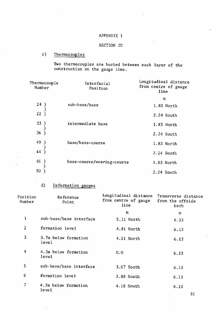
c)
APPENDIX 1
SECTION 20
Thermocouples
Two thermocouples are buried between each layer of the construction on the gauge line.
Thermocoup le Numb e r
24 ) )
22 )
33 ) )
36 )
49 ) )
44 )
45 ) )
50 )
Interfacial Position
s u b - b a s e / b a s e
intermediate base
b a s e / b a s e - c o u r s e
ba se - cours e/we arin g-c ours e
Longitudinal distance from centre of gauge
line
m
1.83 North
2.24 South
1.83 North
2.24 South
1.83 North
2.24 South
1.83 North
2.24 South
Position Number
5
6
7
d) Deformation gauges
R e f e r e n c e Point
s u b - b a s e / b a s e i n t e r f a c e
formation l e v e l
3.7m below f o r m a t i o n l e v e l
4.3m below formation level
sub-base/base interface
formation level
4.3m below formation level
Longitudinaldistance from centre of gauge
line
m
5.11 North
4.81 North
4.51 North
0.0
3.57 South
3.88 South
4.18 South
Transverse distance from the offside
kerb
m
6.13
6.13
6 .13
6 .13
6 .13
6 .13
6 .13
31
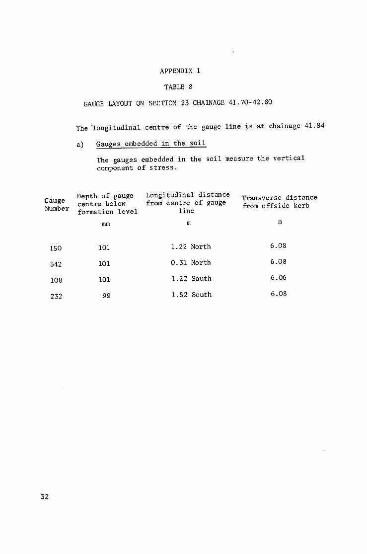
APPENDIX i
TABLE 8
GAUGE LAYOUT ON SECTION 23 CHAINAGE 41.70-42.80
The~longitudinal centre of the gauge line is at chainage 41.84
a) Gauges embedded in the soil
The gauges embedded in the soil measure the vertical component of stress.
Gauge Number
Depth of gauge centre below formation level
mm
Longitudinal distance from centre of gauge
line
m
Transverse distance from offside kerb
m
1so
342
108
232
I01
i01
i01
99
1.22 North
0.31 North
1.22 South
1.52 South
6.08
6.08
6.06
6.08
32
Number
53
51
510
501
6D
42
13
33
02
516
515
17
14
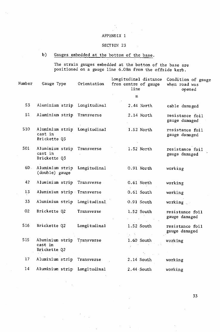
APPENDIX i
SECTION 23
b) Gauges embedded a t the bo t tom o f t he b a s e .
The s t r a i n gauges embedded a t t h e b o t t o m o f t he base a r e p o s i t i o n e d on a gauge l i n e 6.08m from t h e o f f s i d e k e r b .
Gauge Type Orientation Longitudinal d i s t a n c e from c e n t r e o f gauge
line
m
Condition of gauge when road was
opened
Aluminium strip Longitudinal 2.44 North c a b l e damaged
Aluminium strip Transverse 2.14 North r e s i s t a n c e f o i l gauge damaged
A luminium strip cast in Brickette Q3
Longitudinal 1.52 North r e s i s t a n c e f o i l gauge damaged
Aluminium strip cast in Brickette Q3
T r a n s v e r s e 1.52 North r e s i s t a n c e f o i l gauge damaged
Aluminium strip Longitudinal (double) gauge
0.91North working
Aluminium strip T r a n s v e r s e 0.61 North working
Aluminium strip Transverse
Aluminium strip Longitudinal
0.61 South
0.91 South
working
working
Brickette Q2 Transverse 1.52 South resistance foil gauge damaged
Brickette Q2 Longitudinal
Aluminium strip Transverse c a s t i n B r i c k e t t e Q2
Aluminium strip Transverse
1.52 South
1.60 South
2.14 South
resistance foil gauge damaged
working
working
Aluminium strip ~ Longitudinal 2.44 South working
3
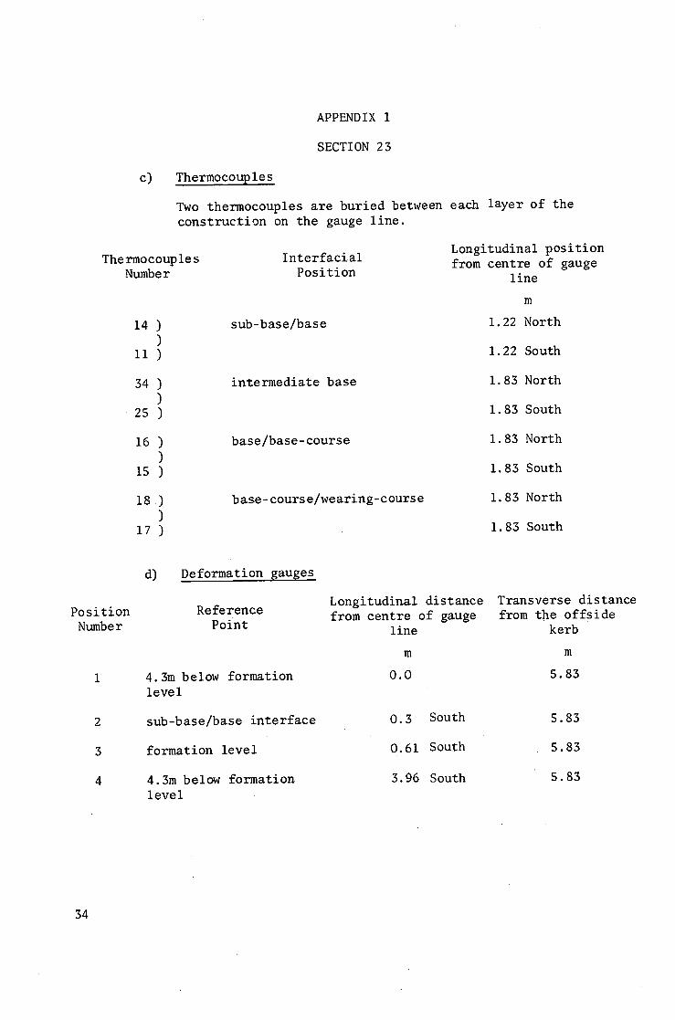
c)
T h e r m o c o u p l e s Numb e r
14 ) )
11 )
34 ) )
. 2 S )
16 ) )
15 )
18 .) )
17 )
Interfacial Position
APPENDIX I
SECTION 23
Thermocouples
Two thermocouples are buried between each layer of the construction on the gauge line.
Longitudinal position from centre of gauge
s u b - b a s e / b a s e
intermediate base
b a s e / b a s e - c o u r s e
base-course/wearing-course
line
m
1.22 North
1.22 South
1.83 North
1.83 South
1.83 North
1.83 South
1.83 North
1.83 South
Position Number
2
3
4
d) D e f o r m a t i o n gauges
R e f e r e n c e Point
4 . 3 m b e l o w f o r m a t i o n l e v e l
s u b - b a s e / b a s e i n t e r f a c e
f o r m a t i o n l e v e l
4.3m be low f o r m a t i o n l e v e l
Longitudinal distance from centre of gauge
line
m
0.0
0.3 South
0.61 South
3.96 South
T r a n s v e r s e distance from the offside
k e r b
m
5.83
5.83
5.83
5.83
34
Gauge Number
263
213
255
257
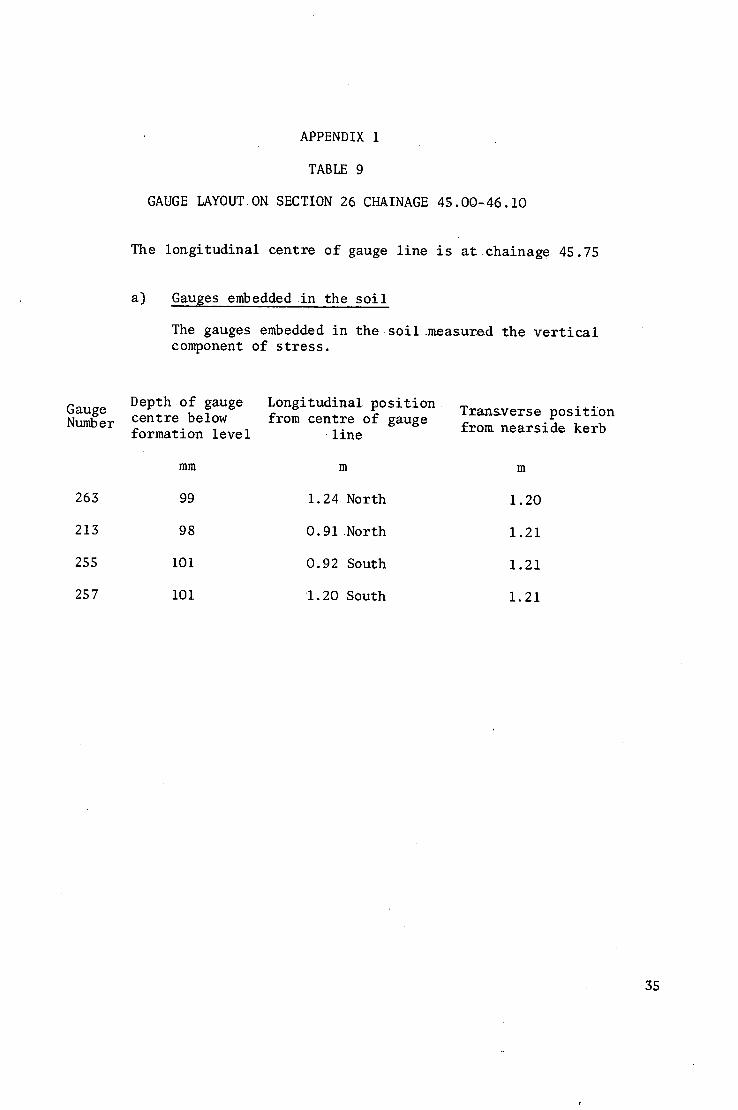
APPENDIX 1
TABLE 9
GAUGE IAYOUTON SECTION 26 CHAINAGE 45.00-46.10
The longitudinal centre of gauge line is at~chainage 45.75
a) Gauges embedded in the soil
The gauges embedded in the soil measured the vertical component of stress.
Depth of gauge Longitudinal position Tranaverse position centre below from centre of gauge formation level line from nearside kerb
mm m m
99 1.24 North 1.20
98 0.91 North 1.21
i01 0.92 South 1.21
I01 1.20 South 1.21
35
Number
39
34
509
508
503
49
52
56
57
ii
41
42
55
48
512
505
Ol
36
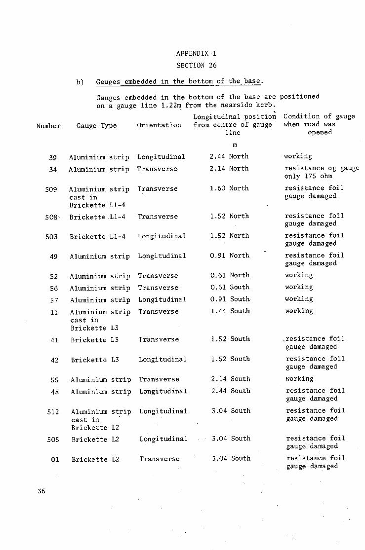
APPENDIX 1
SECTION 26
b) Gauges embedded in the bottom of the base.
Gauges embedded in the bottom of the base are positioned on a gauge line 1.22m from the nearside kerb.
Longitudinal position Gauge Type Orientation
Aluminium strip Longitudinal
Aluminium strip Transverse
from centre of gauge line
m
2.44 North
2.14 North
Aluminium strip cast in Brickette LI-4
Brickette LI-4
Transverse
Transverse
1.60 North
1.52 North
Brickette LI-4 Longitudinal 1.52 North
O.91 North
O.61 North
O.61 South
0.91 South
1.44 South
Aluminium strip Longitudinal
Aluminium strip Transverse
Aluminium strip Transverse
Aluminium strip Longitudinal
Aluminium strip Transverse cast in Brickette L3
Brickette L3 Transverse 1.52 South
1.52 South
2.14 South
2.44 South
3.04 South
Brickette L3 Longitudinal
Aluminium strip Transverse
Aluminium strip Longitudinal
Aluminium strip cast in Brickette L2
Brickette L2
Longitudinal
Longitudinal 3.04 South
Brickette L2 Transverse 3.04 South
Condition of gauge when road was
opened
working
resistance og gauge only 175 ohm
resistance foil gauge damaged
resistance foil gauge damaged
resistance foil gauge damaged
resistance foil gauge damaged
working
working
working
working
.resistance foil gauge damaged
resistance foil gauge damaged
working
resistance foil gauge damaged
resistance foil gauge damaged
resistance foil gauge damaged
resistance foil gauge damaged
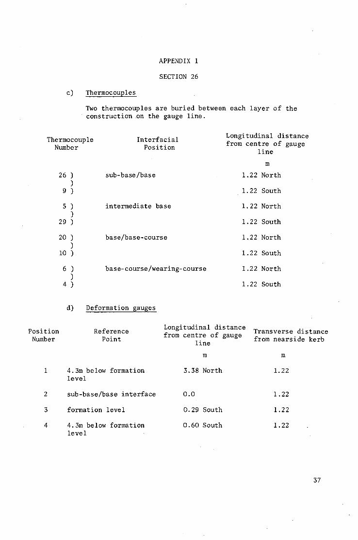
APPENDIX 1
SECTION 26
c) Thermocouples
Two thermocouples are buried between each layer of the construction on the gauge line.
Thermocouple Number
Interfacial Position
Longitudinal distance from centre of gauge
line
m
26 ) )
9)
sub-base/base 1.22 North
1.22 South
s ) )
29 )
intermediate base 1.22 North
1.22 South
20 ) )
lO )
base/base-course 1.22 North
1.22 South
6 ) )
4 )
base-course/wearing-course 1.22 North
1.22 South
Position Number
2
3
4
d) Deformation gauges
Reference Point
4.3m below formation level
sub-base/base interface
formation level
4.3m below formation level
Longitudinal distance from centre of gauge
line
m
3.38 North
0.0
O. 29 South
O. 60 South
Transverse distance from nearside kerb
m
1.22
1.22
1.22
1.22
37
APPENDIX 1
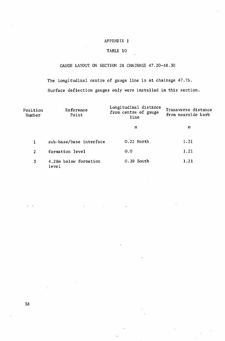
TABLE iO
GAUGE LAYOUT ON SECTION 28 CHAINAGE 47.20-48.30
The longitudinal centre of gauge line is at chainage 47.75.
Surface deflection gauges only were installed in this section.
Position Number
Reference Point
Longitudinal distance from centre of gauge
line
m
Transverse distance from nearside kerb
m
1
2
3
sub-base/base interface
formation level
4.28m below formation level
O. 22 North
0.0
O. 39 South
1.21
1.21
1.21
38
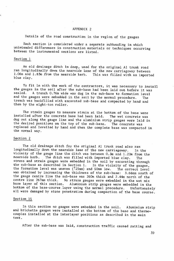
APPENDIX 2
Details of the road construction in the region of the gauges
Each section is considered under a separate Subheading in which unintended differences in construction materials or techniques occurring between the instrumented sections are listed.
Section 1
An old drainage ditch im deep, used for the original A1 trunk road ran longitudinally down the nearside lane of the new carriageway between 1.06m and 1.83m from the nearside kerb. This was filled with an imported blue clay.
To fit in with the work of the contractors, it was necessary to install the gauges in the soil after the sub-base had been laid out before it was sealed. A trench 0.76m wide was dug in the sub-base to formation level and the gauges were embedded in the soil by the normal procedure. The trench was backfilled with excavated sub-base and compacted by hand and then by the eight-ton roller.
The strain gauges to measure strain at the bottom~of the base were installed after the concrete base had been laid. The wet concrete was dug out along the gauge line and the aluminium strip gauges were laid in the desired positions on the top of the sub-base. The concrete was replaced and levelled by hand and then the complete base was compacted in the normal way.
Section 2
The old drainage ditch for the original A1 trunk road also ran longitudinally down the nearside lane of the new carriageway. In the vicinity of the gauge line the ditch was between 0.3m and 1.22m from the nearside kerb. The ditch was filled with imported blue clay. The stress and strain gauges were embedded in the soil by excavating through the sub-base as described in Section i. In the vicinity of the gauges, the formation level was uneven (~25mm) and SOmm low. The correct level was obtained by increasing the thickness of the sub-base: 3.66mm south of the gauge centre line the sub-base was 26Om thick and 2.44m north of the centre line 267mm thick. No strain gauges were embedded in the wet mix base layer of this section. Aluminium strip gauges were embedded in the bottom of the base-course layer using the normal procedure. Unfortunately all were damaged by stone penetration during compaction of the base course.
Section 15
In this section no gauges were embedded in the soil. Aluminium strip and brickette gauges were installed at the bottom of the base and thermo- couples installed at the interlayer positions as described in the main text.
After the sub-base was laid, construction traffic caused rutting and
39
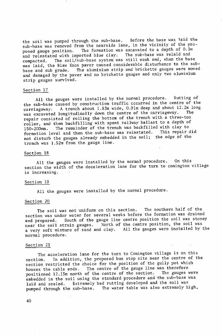
the soil was pumped through the sub-base. Before the base was laid the sub-base was removed from the nearside lane, in the vicinity of the pro- posed gauge position. The formation was excavated to a depth of 0.3m and reinstated with imported blue clay. The sub-base was relaid and compacted. The soil/sub-base system was still weak and, when the base was laid, the Blaw Knox paver caused considerable disturbance to the sub- base and sub grade. The aluminium strip and brickette gauges were moved and damaged by the paver and no brickette gauges and only two aluminium
strip gauges survived.
Section 17
All the gauges were installed by the normal procedure. Rutting of the sub-base caused by construction traffic cccurred in the centre of the carriageway. A trench about 1.83m wide, O.91m deep and about 12.2m long was excavated longitudinally down the centre of the carriageway. The repair consisted of rolling the bottom of the trench with a three-ton roller, and then backfilling with spent railway ballast to a depth of 150-2OOmm. The remainder of the trench was backfilled with clay to formation level and then the sub-base was reinstated. This repair did not disturb the gauges already embedded in the soil; the edge of the trench was 1.52m from the gauge line.
Section 18
All the gauges were installed by the normal procedure. On this section the width of the deceleration lane for the turn to conington village
is increasing.
Section 19
All the gauges were installed by the normal procedure.
Section 20
The soil was not uniform on this section. The southern half of the section was under water for several weeks before the formation was drained and prepared. South of the gauge line centre position the soil was stoney near the soil strain gauges. North of the centre position, the soil was a very soft mixture of sand and clay. All the gauges were installed by the
normal procedure.
Section 23
The acceleration lane for the turn to Conington village is on this section. In addition, the proposed bus stop site near the centre of the section restricted the choice for the position of the gully pot which houses the cable ends. The centre of the gauge line was therefore positioned 12.i5m north of the centre of the section. The gauges were embedded in the soil using the standard procedure and the sub-base was laid and sealed. Extremely bad rutting developed and the soil was pumped through the sub-base. The water table was also extremely high,
40
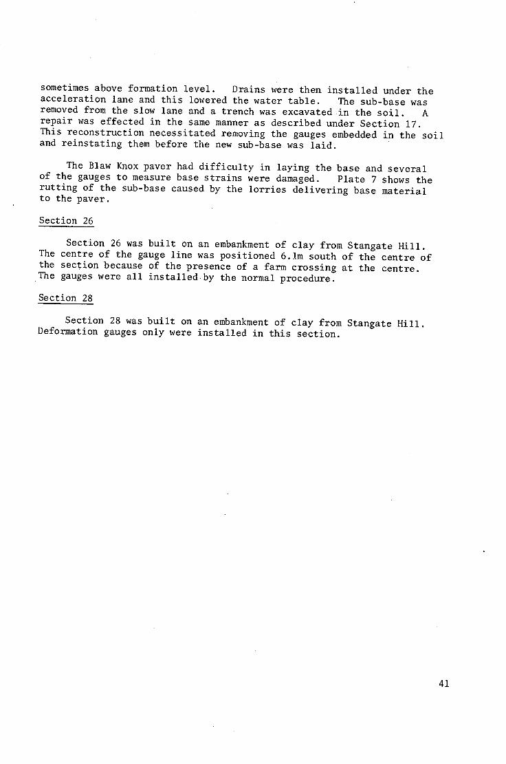
sometimes above formation level. Drains were then installed under the acceleration lane and this lowered the water table. The sub-base was removed from the slow lane and a trench was excavated in the soil. A repair was effected in the same manner as described under Section 17. This reconstruction necessitated removing the gauges embedded in the soil and reinstating them before the new sub-base was laid.
The Blaw Knox paver had difficulty in laying the base and several of the gauges to measure basestrains were damaged. Plate 7 shows the rutting of the sub-base caused by the lorries delivering base material to the paver.
Section 26
Section 26 was built on an embankment of clay from Stangate Hill. The centre of the gauge line was positioned 6.1m south of the centre of the section because of the presence of a farm crossing at the centre. The gauges were all installedby the normal procedure.
Section 28
Section 28 was built on an embankment of clay from Stangate Hill. Deformation gauges only were installed in this section.
41
0 t -
n . ,
IE ¢n
u_
B
en
I1-
B-
I1-
i | . | ~
I! I 0
¢- m ¢,~ iI- (ll
| | I
¢-
8 I ' -
..,,I
C.) v
k ~ F - -
0
, m
Q
v <
en
_1
lift
\ x
0 0
"6
r -
P
-36+00
35+00
34+00
33+00
32+00
31+00
30t00
29+ O0
28+00
27+00
26+00
25+00
24+00
23+00
22, O0
21+00
20+00
19+00 18+00
17+00
i 16+00 15÷00
14+00
13+00
- 0 E
" 0
E ~ >~.~E D
C
• ( / I
= o g g (-) b-. 0 .--~ n" 0 Q •
E n ' O o O < E ~m 2 U I..~_ 0 ,,..J n," r ' ~ a ( z
t l
E LL
m
C
0 m
m r~
a, < n -
O ~E
B
:E nn O
~9 C~
np
Z £3
r-
i7+00
;6+00
5+00
4+00
3+00
2#00
I tO0 3÷00
)+00 ~+00 'tO0 ;+00
i+O0
+00
tOO
+00
tOO
40+00
39+00
38+00
37+00
36+00
z
X w
I,LI
I.I--
Z
Z
Z C ~
I . I .
--...I
.--,I
W Z
&.l..
f
"O
. J
u
C3.
E u
c~
u
4 ~ 3
2 ~D
t -
e l
C~
4 3
X
o O
C~
"O O
o
U
N
c~ C~
O
C Q .
0 . i u
Q .
0
D n -
E E
O _ L n
O -
A
m
I - -
w
w
N w m Q -
z
m
w
z
m
w
0 O0
° ~ . J
E . _ t'-
LU
n'
Cl
N
C~ '-!
U "><
Cl ( ~
.c
O ) t -
. _ ,-.j
( ,0 C
.o O0
. .0 0
X Cl 0
( J
0 ~ C
tl)
L/)
u II}
Crl . c
0 LLI
u u~ i
. 0
L..
,i'-
: o
" . J O
n."
" 0 tO
O . O . 0
C_)
E E
C ) 0 - -
O m L n
O - -
Lm)
. . ,J
C ~ N
0--
Z
I-.-.
I,.i.I ,ml
Z
i.m
0 ) . m LL.
0 U
" 0
C
u
0 U
..£3 0
¢.)
~ C O 0
~ E U L -
ILl
j
u \
C "~ \ c-
\
\
C
O,
. 0
I--: n"
_..I
C 'r"
~o
~0 .,0
n*"
t - O
O.
F-.: .. o
> 0 u
o
01
0
u u ° I , ~ " 0
7O C
UJ
0"1 C
"D
E E
0 o4 z
¢.a"3
... .4
c ~ c ~
i..,s.
I I
Wearing course
Etectrica[ components
Brass gauge casing
~ Single core connectors
Locking screw
Base course
Brass c o t t e r
Nyton cotter
Locking screw
Core - ~ - ~ j T r a n s d u c e r
Inductance f coil
Compression gap
B~-ass ring
Helical spring
Gauge foot
Base
Anchor rod
Brass rod
P, V.C. tube
Compression gap
Sub-base Cement grout plug
Subgrade
Fig. 5. SECTIONAL VIEW OF GAUGE INSTALLATION FOR THE MEASUREMENT OF TRAHSIENT .OEFORMATION OF SUB-BASE, BASE ANO SURFACING
Compression
I Tension i
Time
Vertical soil
strain
Vertical sol t
s t r e s s
Horizontal longitudinal base strain
Horizontal transverse
base strain
Vehicle type
Laboratory mandator
Single rear axle articulated
Double rear axle articulated
I
TOTAL VERTICAL
DEFORMATION
Fig. G. STRESSES STRAIHS AND DEFORMATIONS PRODUCED IN A ROAD BY THE PASSAGE OF COMMERCIAL VEHICLES
l
I
L I J I---
. - J rl
._c
P Jj i
L~
0 U E ~
I@
0 . . . D
q~ - i -
E
E m
,,:£
C~j
W ~m
J o~
C~
o q C
p ~
O ~J
j~O
I,kl p - < ..A Q_
~ i ~ , ~ : ~ , ~ ' . , ~ .i ~ ~
.!
UJ I - -
.--I a _
0 C~
¢11
e l
E
. Q
e ¢11
O)
._=
0 .-r-
LLI I - -
.--I Q.
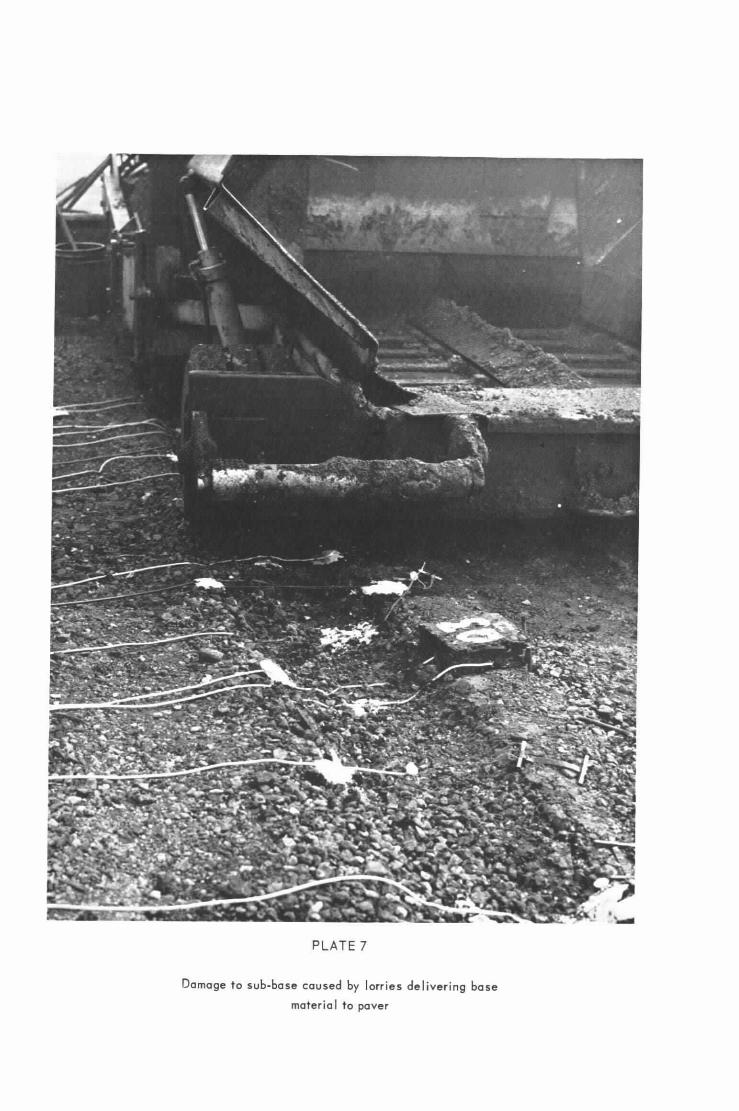
PLATE 7
Damage to sub-base caused by lorries delivering base material to paver

(1887) Dd635271 3,250 12/69 H.P.Ltd., G1915 P R I N T E D IN E N G L A N D
ABSTRACT
Instrumentation of the full-scale experiment on AI trunk road at Conington, Huntingdonshire: J.F. POTTER, H.C. MAYHEW and A.P. MAYO: Ministry of Transport, RRL Repdrt LR 296: Crowthorne, 1969 (Road Research Laboratory). This paper describes the instrumentation of the full-scale experiment on the south bound carriageway of the A1 trunk road at Conington, Huntingdonshire. The experiment is designed to compare the performance of vari- ous gravel aggregate used in the base and base course layers in conjunction with bitumen and tar binders.
A brief description is given of the gauges used to measure transient atresses and strains in the sub-grade, strain at the bottom of the base and the surfacing, and the total and component transient and permanent deformations of the pavement and subgrade. The methods used for instal- ling these gauges are described in detail and results are given of preliminary measurements made when the road was loaded by commercial vehicles.
Two appendices are included, one giving the gauge lay-out on the instrumented sections and the other giving details of the road construction in the region of the gauges.
ABSTRACT
Instrumentation of the full-scale experiment on AI trunk road at Conington, Huntingdonshire': J.F. POTTER, H.C. MAYHEW and A.P. MAYO: Ministry of Transport, RRL Report LR 296: Crowthorne, 1969 (Road Research Laboratory). This paper describes the instrumentation of the full-scale experiment on the south bound carriageway of the A1 trunk road at Conington, Huntingdonshire. The experiment is designed to compare the performance of vari- ous gravel aggregate used in the base and base course layers in conjunction with bitumen and tar binders.
A brief description is given of the gauges used to measure transient atresses and strains in the sub-grade, strain at the bottom of the base and the surfacing, and the total and component transient and permanent deformations of the pavement and subgrade. The methods used for instal- ling these gauges are described in detail and results are given of preliminary measurements made when the road was loaded by commercial vehicles.
Two appendices are included, one giving the gauge lay-out on the instrumented sections and the other giving details of the road construction in the region of the gauges.


