
Risers for DeepwaterFPSO’sJohn Bob-ManuelSenior Engineer2H Offshore Engineering Ltd.
March 2013
Learn more at www.2hoffshore.com
of #
Agenda
2H overview
Challenges of Deepwater Operations
Freestanding Riser Overview
Riser Configurations and Component Design
Case Study
Alternatives
3
Learn more at www.2hoffshore.com
of #
Learn more at www.2hoffshore.com

of #
ServicesServices
Learn more at www.2hoffshore.com
of #
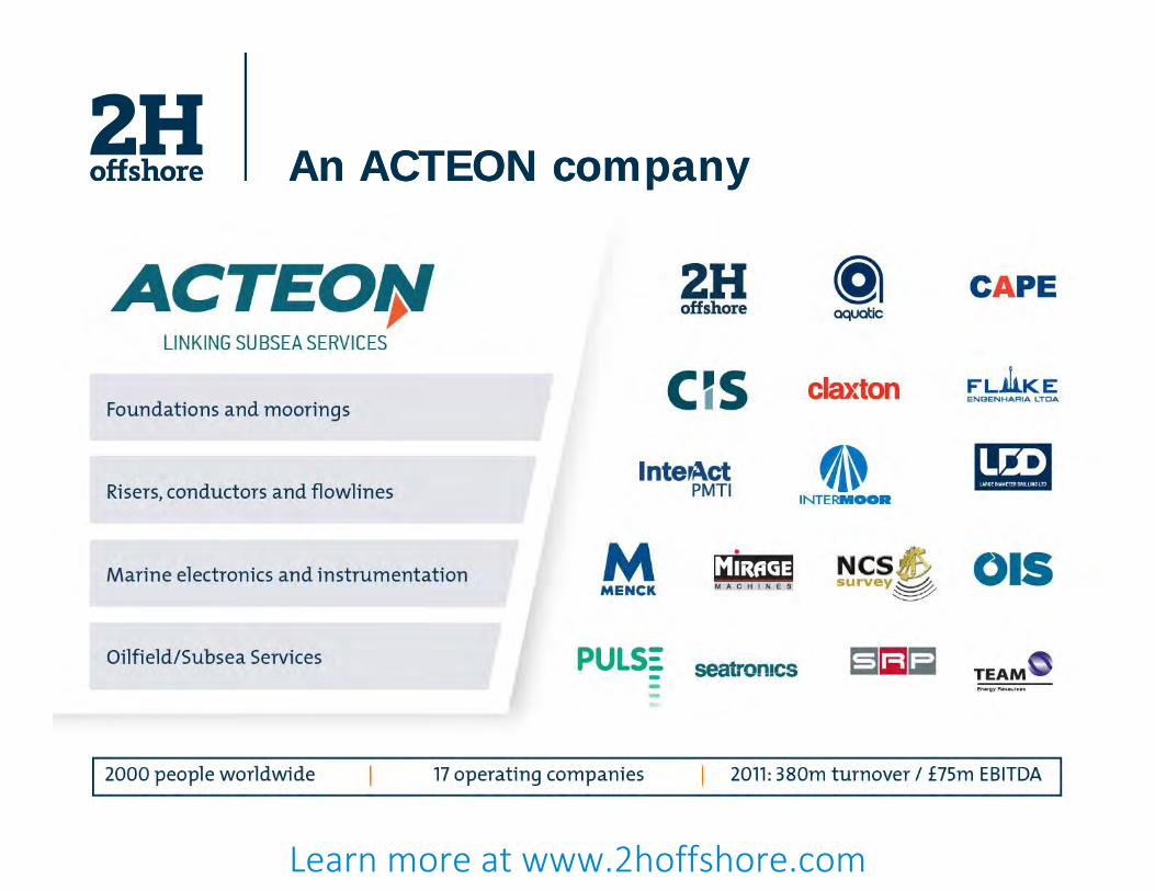
An ACTEON companyAn ACTEON company
Learn more at www.2hoffshore.com

of #
Learn more at www.2hoffshore.com
of #
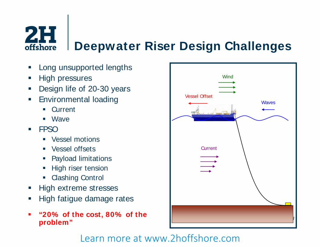
Deepwater Riser Design Challenges
Long unsupported lengths High pressures Design life of 20-30 years Environmental loading
Current Wave
FPSO Vessel motions Vessel offsets Payload limitations High riser tension Clashing Control
High extreme stresses High fatigue damage rates
“20% of the cost, 80% of the problem”
Vessel Offset
Wind
Current
Waves
Learn more at www.2hoffshore.com
of #
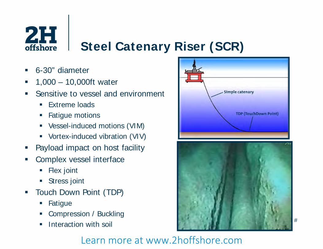
Steel Catenary Riser (SCR)
6-30” diameter 1,000 – 10,000ft water Sensitive to vessel and environment
Extreme loads Fatigue motions Vessel-induced motions (VIM) Vortex-induced vibration (VIV)
Payload impact on host facility Complex vessel interface
Flex joint Stress joint
Touch Down Point (TDP) Fatigue Compression / Buckling Interaction with soil
Learn more at www.2hoffshore.com

of #
Flexible Risers
Compliant response Not fatigue sensitive Installation friendly Limitations
Water depth Pressure Diameter Temperature
Expensive Reliability? Availability?
Carcass Pressure sheath Pressure Armour Layer
Tensile Armour Layer External sheath
Learn more at www.2hoffshore.com
of #
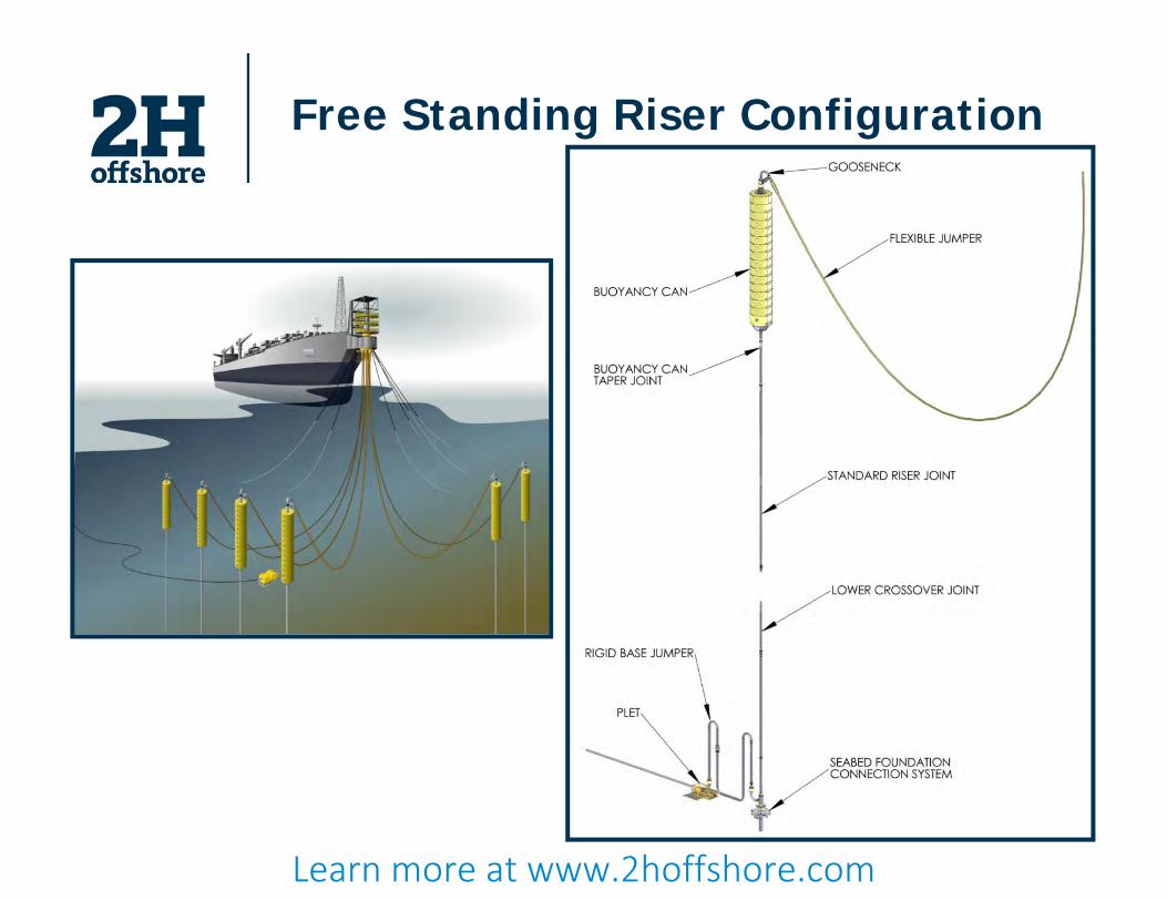
Free Standing Riser Configuration
Learn more at www.2hoffshore.com
of #
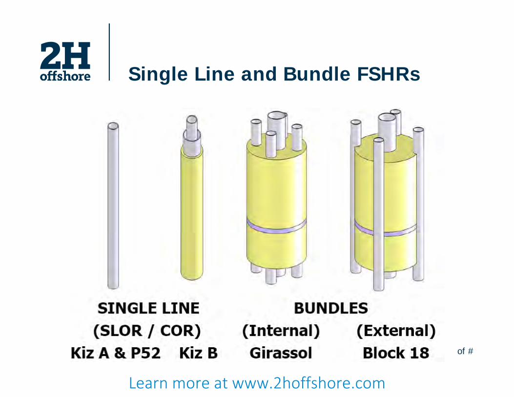
Single Line and Bundle FSHRs
Learn more at www.2hoffshore.com
of #
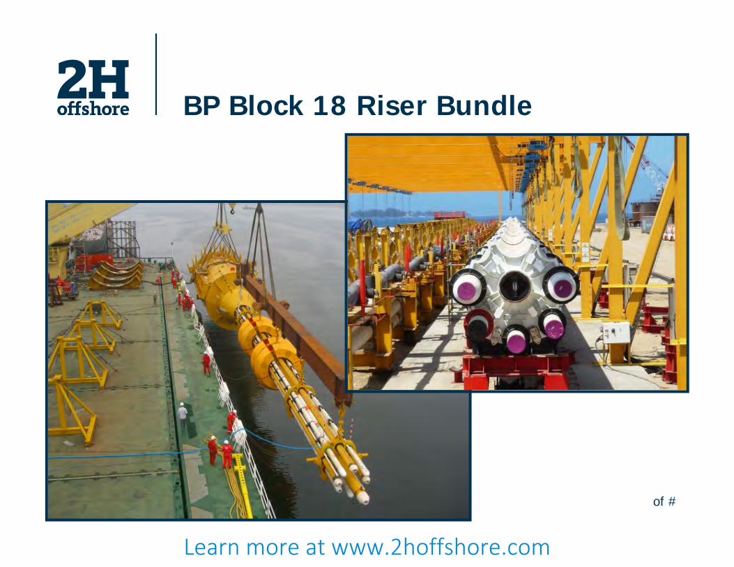
BP Block 18 Riser Bundle
Learn more at www.2hoffshore.com

of #
Buoyancy Tank
Maintain riser verticality Steel plate structure Flat or hemispherical ends Pressure balanced design Water / nitrogen filled Compartmentalised
Design up to: 40m tall 6m diameter ~700Te upthurst
Limited by: Fabrication site Handling / Installation restrictions
Learn more at www.2hoffshore.com
of #
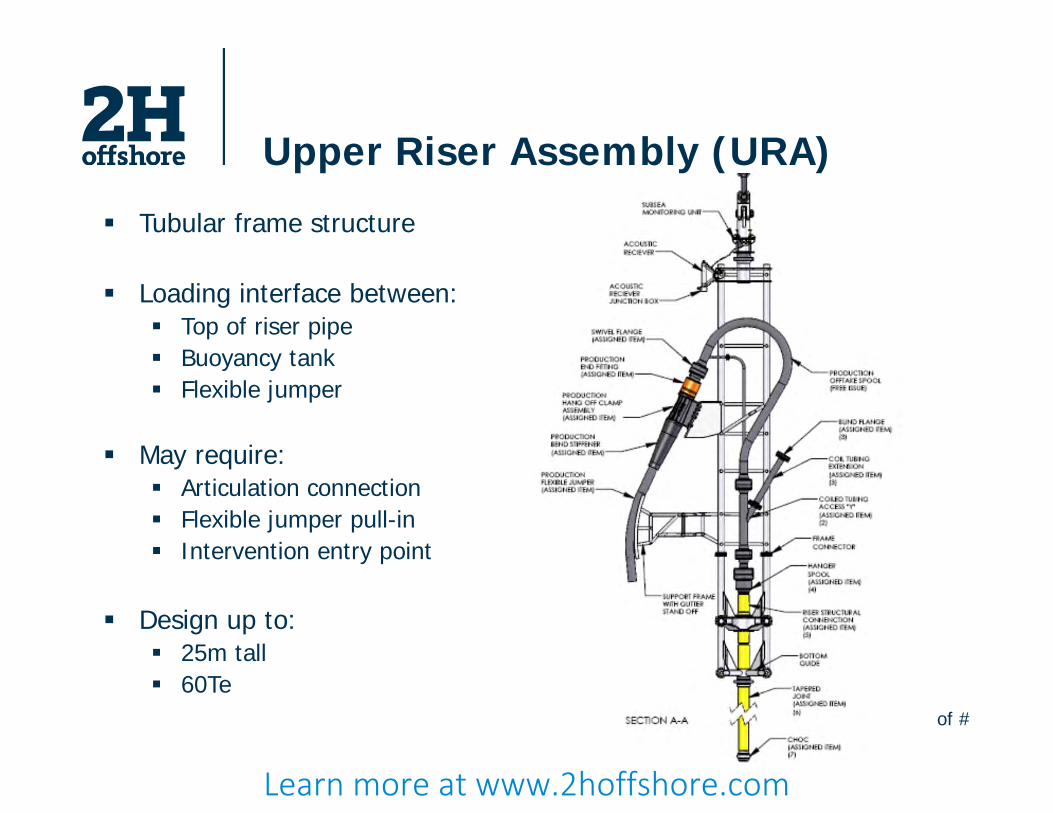
Upper Riser Assembly (URA)
Tubular frame structure
Loading interface between: Top of riser pipe Buoyancy tank Flexible jumper
May require: Articulation connection Flexible jumper pull-in Intervention entry point
Design up to: 25m tall 60Te
Learn more at www.2hoffshore.com

of #
Upper Assembly - Alternatives
Learn more at www.2hoffshore.com
of #
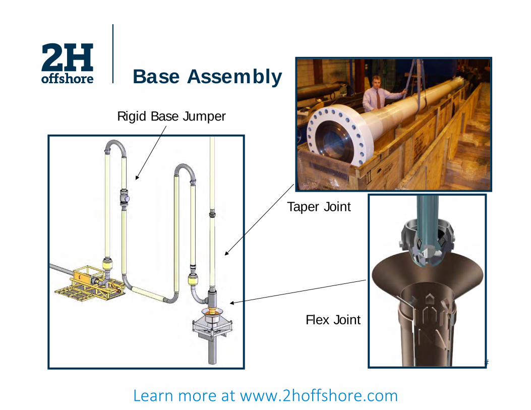
Base Assembly
Flex Joint
Taper Joint
Rigid Base Jumper
Learn more at www.2hoffshore.com
of #
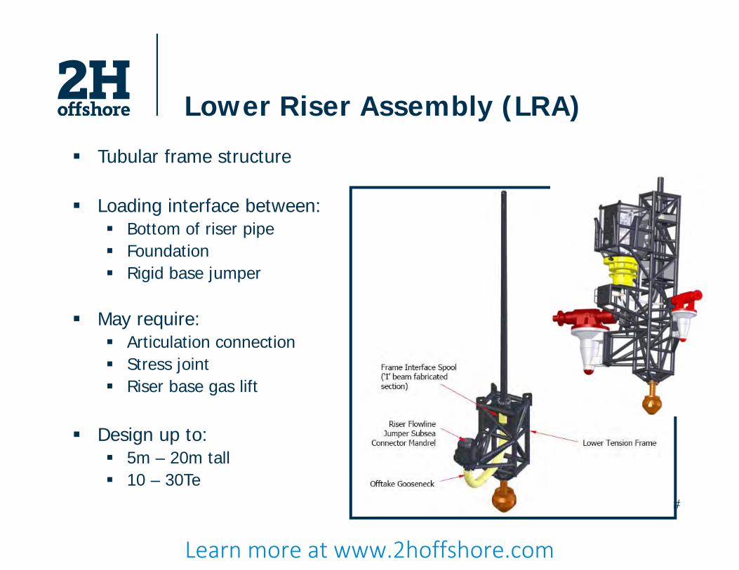
Lower Riser Assembly (LRA)
Tubular frame structure
Loading interface between: Bottom of riser pipe Foundation Rigid base jumper
May require: Articulation connection Stress joint Riser base gas lift
Design up to: 5m – 20m tall 10 – 30Te
Learn more at www.2hoffshore.com
of #
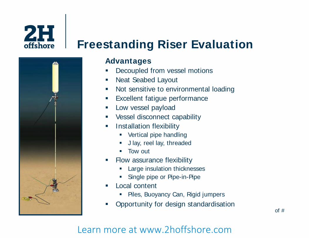
Freestanding Riser EvaluationAdvantages Decoupled from vessel motions Neat Seabed Layout Not sensitive to environmental loading Excellent fatigue performance Low vessel payload Vessel disconnect capability Installation flexibility
Vertical pipe handling J lay, reel lay, threaded Tow out
Flow assurance flexibility Large insulation thicknesses Single pipe or Pipe-in-Pipe
Local content Piles, Buoyancy Can, Rigid jumpers
Opportunity for design standardisation
Learn more at www.2hoffshore.com
of #
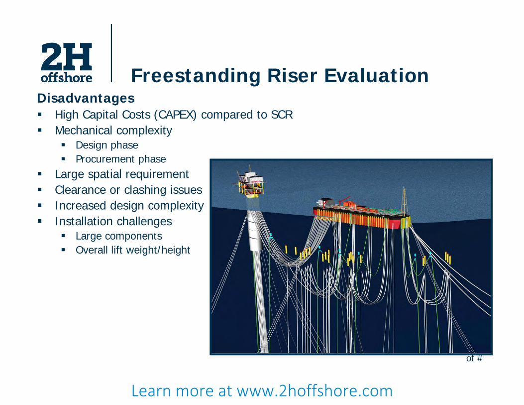
Freestanding Riser EvaluationDisadvantages High Capital Costs (CAPEX) compared to SCR Mechanical complexity
Design phase Procurement phase
Large spatial requirement Clearance or clashing issues Increased design complexity Installation challenges
Large components Overall lift weight/height
Learn more at www.2hoffshore.com
of #
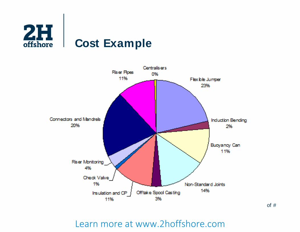
Cost Example
Learn more at www.2hoffshore.com

of #
Freestanding Risers to Date
Type Field Status Owner/Field Operator
Yr. Installed Region
Water Depth Vessel
(ft) (m)
Green Canyon 29/Garden Banks 388
De-commissionedPlacid Oil Company/Ensearch
1988/1994 GoM 1,529/2,096 466/639 Semi-Sub
Girassol Operating Total Elf 2001 Angola 4,430 1,350 Spread Moored FPSO
Rosa Operating Total Elf 2007 Angola 4,430 1,350 Spread Moored FPSO
BP Greater Plutonio Operating BP 2007 Angola 4,300 1,311 Spread Moored FPSO
Kizomba A/B Operating Exxon 2003/2005 Angola 3,330 to 4,200
1,006 to 1,280
Spread Moored FPSO
Block 31 NE Installed BP 2010 Angola 6,890 2,100 Turret Moored FPSO
Roncador P-52 Operating Petrobras 2007 Campos Basin 5,906 1,800
Semi-SubFPU
Containment FSH Completed - 2010 GoM 4,992 1,500 FPU
*Cascade/Chinook Detailed Design/Execute Petrobras 2011 GoM 8,531 2,600 Turret
Moored FPSO
Bun
dle
Sing
le L
ine
Learn more at www.2hoffshore.com

of #
PSVM – Overview
Block 31, offshore Angola
Putao, Satunro, Venus and Marte fields
1800m to 2100m (5900ft to 6890ft) water depth
9 Single Leg Hybrid Risers (SLHRs) connected to an externally mounted turret moored FPSO
Deepest SLHR in WoA
J-lay installation using Balder
Learn more at www.2hoffshore.com

of #
W-1 (FP-RS05)
W-2 (FP-RS04)
W-3 (FP-RS03)
W-4 (FP-WR01)
W-5 (FP-RS02)
SE-3 (FP-RS07)SE-4 (FP-RS06)
SE-1 (FP-RS09)
SE-2 (FP-RS08)
Service PSVM
Production 1 x 10in Insulated Clad CS 2 x 12in Insulated Clad CS
Gas Lift 1 x 8in Insulated Nominal CA Water Injection 1 x 14in Non-insulated Polyethylene Lined Gas Injection 1 x10in Non-insulated Nominal CA
Service 1 x 10in Non-insulated Nominal CA 2 x 12in Non-insulated Nominal CA
Dynamic Umbilical 4 x Main Control Umbilical
1 x Gas Lift Control Umbilical 1 x Spare Main Control Umbilical
Plutao
Marte
Saturno
Venus
FPSO
PSVM
Learn more at www.2hoffshore.com

of #
PSVM
Project started in 2005
2H was responsible for…
Detailed component structural design
Detailed global analysis
Installation analysis
Procurement management
URA
Buoyancy Tankand flexible joint
Riserbasespool LRA
Riser base foundationand flexible joint
X’OverJoint
X’OverJoint
Learn more at www.2hoffshore.com
of #
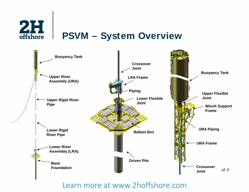
PSVM – System Overview
Crossover Joint
Lower Flexible Joint
Ballast Box
Driven Pile
LRA Frame
Piping
URA Piping
Buoyancy Tank
Upper Flexible Joint
Winch Support Frame
Crossover Joint
URA FrameLower Riser Assembly (LRA)
Buoyancy Tank
Base Foundation
Upper Rigid Riser Pipe
Lower Rigid Riser Pipe
Upper Riser Assembly (URA)
Learn more at www.2hoffshore.com

of #
PSVM – Driven Pile
Driven pile self-penetrates into soil Hydraulic hammer drives the pile to required depth Pile length depends on soil conditions
Learn more at www.2hoffshore.com
of #
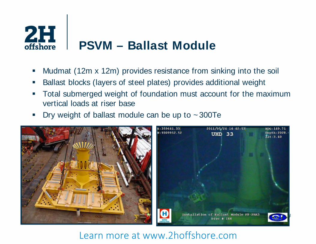
PSVM – Ballast Module
Mudmat (12m x 12m) provides resistance from sinking into the soil Ballast blocks (layers of steel plates) provides additional weight Total submerged weight of foundation must account for the maximum
vertical loads at riser base Dry weight of ballast module can be up to ~300Te
Learn more at www.2hoffshore.com
of #
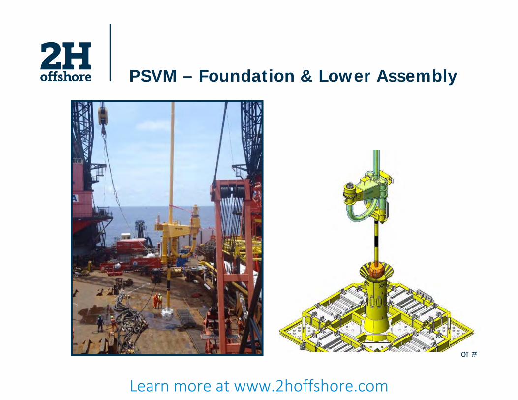
PSVM – Foundation & Lower Assembly
Learn more at www.2hoffshore.com

of #
PSVM – Upper Assembly
Trussed frame size is 3m x 1.5m, 22.4m long Hollow parts must withstand hydrostatic
collapse up to 250m depth Upper crossover joint Flexible joint
Learn more at www.2hoffshore.com
of #
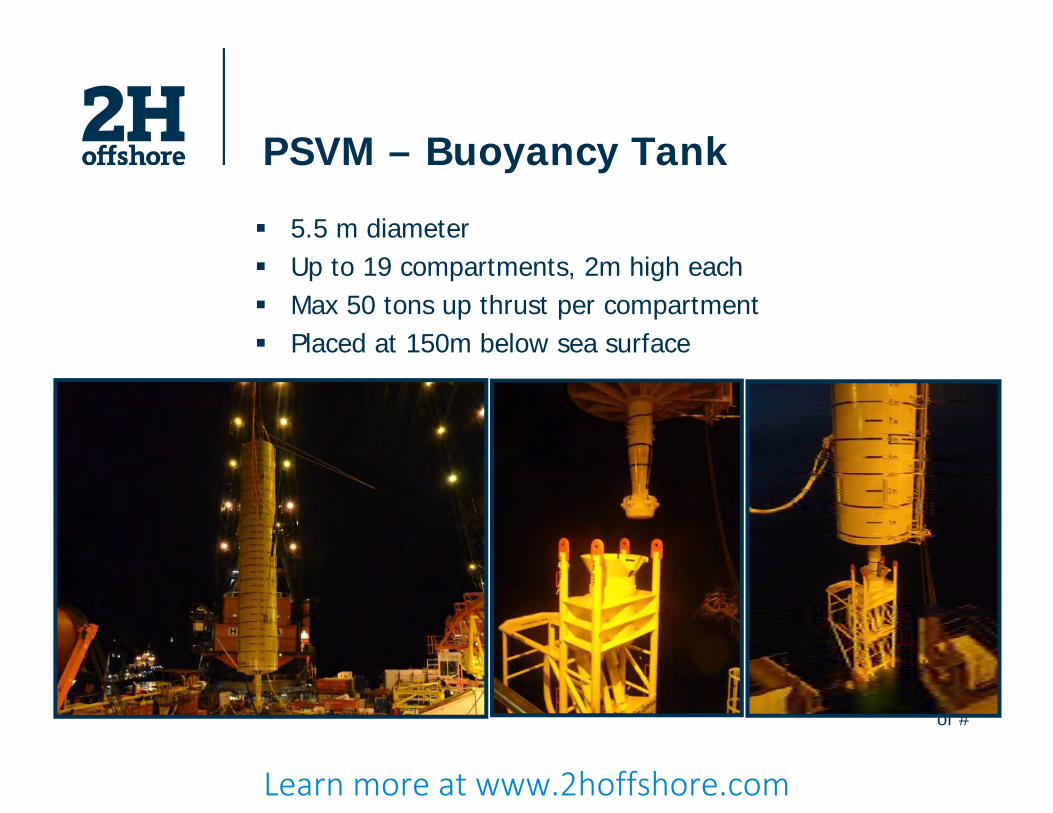
PSVM – Buoyancy Tank
5.5 m diameter Up to 19 compartments, 2m high each Max 50 tons up thrust per compartment Placed at 150m below sea surface
Learn more at www.2hoffshore.com
of #
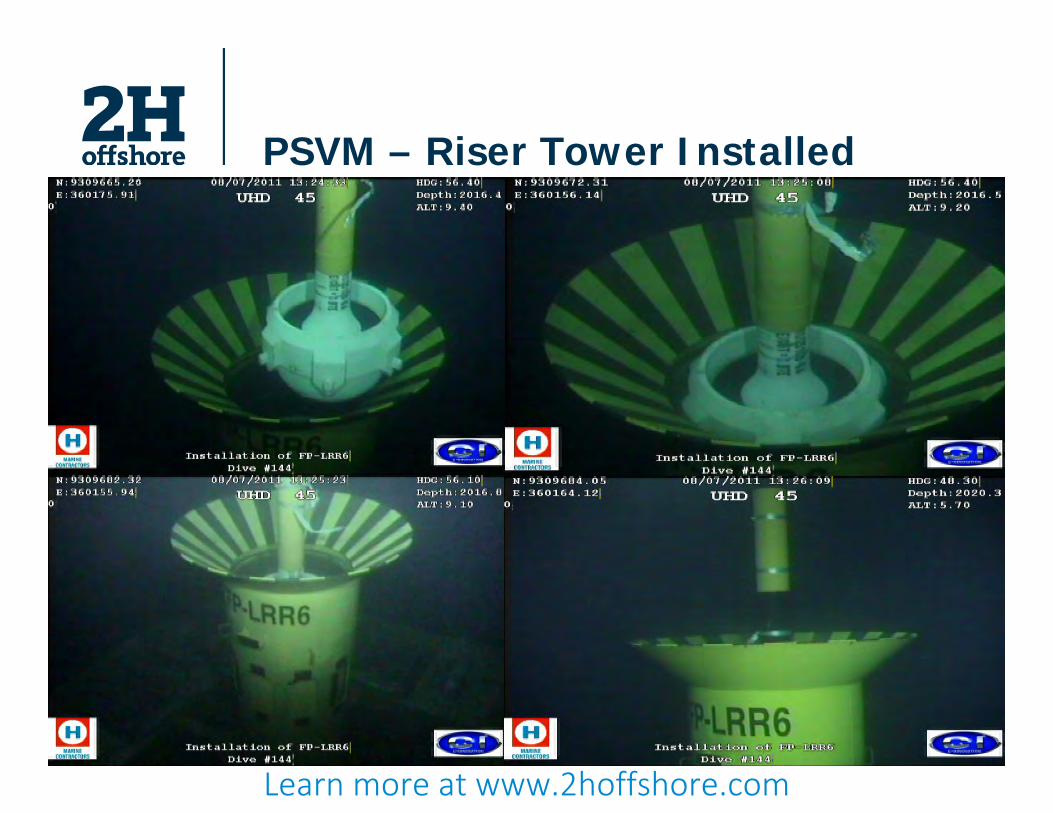
PSVM – Riser Tower Installed
Learn more at www.2hoffshore.com

of #
Alternatives – Group SLORs
Grouped arrangement Reduced cost - top assembly
optimisation Ease of pre-installation Ease of field layout and pipe
routing
Learn more at www.2hoffshore.com

of #
Alternatives – Buoyancy Supported Risers
Concept developed in the 90’s by DeepStar for WD of 1000m
Being developed for Guara and Lula pre-salt fields
Learn more at www.2hoffshore.com

of #
Conclusion Key interfaces
Flexible end terminations and bend restrictors
Key parameters affecting design Turret vs spread moored Position of riser hangoff Space for riser end terminations Maximum hang off weight Vessel motions Heading analysis Mooring analysis
Interface mechanism with FPSO contractor needs establishing early on!
Selection of system required during field layout exercise. The solution will not necessarily be cost driven but the solution needs to be technically engineered.
Learn more at www.2hoffshore.com
of #
Thank you for your time.
Questions?
Further information:
+44 1483 774900
Learn more at www.2hoffshore.com

Learn more at www.2hoffshore.com


