
International Scholarly Research NetworkISRN Mechanical EngineeringVolume 2012, Article ID 208760, 10 pagesdoi:10.5402/2012/208760
Review Article
A Review of Additive Manufacturing
Kaufui V. Wong and Aldo Hernandez
Department of Mechanical and Aerospace Engineering, University of Miami, Coral Gables, FL 33146, USA
Correspondence should be addressed to Kaufui V. Wong, [email protected]
Received 29 May 2012; Accepted 17 June 2012
Academic Editors: N. Anifantis and F. Findik
Copyright © 2012 K. V. Wong and A. Hernandez. This is an open access article distributed under the Creative CommonsAttribution License, which permits unrestricted use, distribution, and reproduction in any medium, provided the original work isproperly cited.
Additive manufacturing processes take the information from a computer-aided design (CAD) file that is later converted to astereolithography (STL) file. In this process, the drawing made in the CAD software is approximated by triangles and slicedcontaining the information of each layer that is going to be printed. There is a discussion of the relevant additive manufacturingprocesses and their applications. The aerospace industry employs them because of the possibility of manufacturing lighterstructures to reduce weight. Additive manufacturing is transforming the practice of medicine and making work easier forarchitects. In 2004, the Society of Manufacturing Engineers did a classification of the various technologies and there are at leastfour additional significant technologies in 2012. Studies are reviewed which were about the strength of products made in additivemanufacturing processes. However, there is still a lot of work and research to be accomplished before additive manufacturingtechnologies become standard in the manufacturing industry because not every commonly used manufacturing material can behandled. The accuracy needs improvement to eliminate the necessity of a finishing process. The continuous and increasing growthexperienced since the early days and the successful results up to the present time allow for optimism that additive manufacturinghas a significant place in the future of manufacturing.
1. Rapid Prototyping
The first form of creating layer by layer a three-dimensionalobject using computer-aided design (CAD) was rapid pro-totyping, developed in the 1980’s for creating models andprototype parts. This technology was created to help the real-ization of what engineers have in mind. Rapid prototypingis one of the earlier additive manufacturing (AM) processes.It allows for the creation of printed parts, not just models.Among the major advances that this process presentedto product development are the time and cost reduction,human interaction, and consequently the product develop-ment cycle [1], also the possibility to create almost any shapethat could be very difficult to machine. However, at thepresent time it is not yet adopted in the manufacturingsector, but scientists, medical doctors, students and profes-sors, market researchers, and artists use it [2–4]. With rapidprototyping, scientists and students can rapidly build and
analyze models for theoretical comprehension and studies.Doctors can build a model of a damaged body to analyze itand plan better the procedure, market researchers can seewhat people think of a particular new product, and rapidprototyping makes it easier for artists to explore theircreativity.
The steps involved in product development using rapidprototyping are shown in Figure 1. Here, it can be seen thatcreating models faster save a lot of time and there is thepossibility of testing more models.
At the present time, the technologies of rapid prototypingare not just used for creating models, with the advantagesin plastic materials it has been possible to create finishedproducts, of course at the beginning they were developedto expand the situations tested in the prototyping process[5]. Nowadays, these technologies have other names like 3Dprinting, and so forth, but they all have the origins of rapidprototyping [2, 6]. According to Wohler’s report 2011 the

2 ISRN Mechanical Engineering
Designconcepts
Parametricdesign(CAD)
Analysis andoptimization
(CAE)
Creation ofprototypes
(RP)
Prototypetesting andevaluation
NoMeet
designcriteria
Yes
Final product
Figure 1: Product development cycle [2].
growth rate for 2010 was 24.1%. The compound annualgrowth rate for the industry’s history, until 2010, is 26.2 per-cent [7, 8]. This growth shown in Figure 2.
In addition, it is important to notice that rapid manufac-turing became possible by other technologies, which arecomputer-aided design (CAD), computer-aided manufac-turing (CAM), and computer numerical control (CNC). Thisthree technologies combined together made possible theprinting of three-dimensional objects [2, 5, 11].
Rapid prototyping is still not the best solution for allcases, in some cases CNC machining processes still need to beused. Parts dimension could be larger than available additivemanufacturing printers [8]. Materials for rapid prototypingare still limited. It is clear that at least it is possible to printmetals and ceramics but not all commonly used manufactur-ing materials [11].
In Figure 3, there is an overview of the different additivemanufacturing processes that are going to be further dis-cussed. Here in this figure adapted from [11], the criterionused is to classify these processes into liquid base, solidbased, and powder based. The processes included in thisreview are considered the most relevant in the past, andpromising for the future of the industry. The processes con-sidered are stereolithography (SL), Polyjet, fused depositionmodeling (FDM), laminated object manufacturing (LOM),3D printing (3DP), Prometal, selective laser sintering (SLS),laminated engineered net shaping (LENS), and electronbeam melting (EBM). The liquid-and powder-based pro-cesses seem more promising than solid-based processes ofwhich LOM is the predominant one today. In 2004 [11],EBM, Prometal, LENS, and Polyjet were nonexistent.
These technologies were first created to produce models,but they have expanded since then. In the chart is presented asurvey made by Wohlers in which 24 manufacturers partici-pated and so did 65 services of 5000+ users and costumers. InFigure 4 is shown the amount of responses received by thesecompanies [12].
2. Stereolithography
Stereolithography (SL), developed by 3D Systems, Inc., wasthe first and is most widely used process of rapid prototyping,so, in the past the two terms were used synonymously. This is
0
1000
2000
3000
4000
5000
6000
7000
1995 2000 2005 2010
System sales
Figure 2: Growth of rapid prototyping [9]. Source. Wohler’s report2010 adapted from [10].
a liquid-based process that consists in the curing or solid-ification of a photosensitive polymer when an ultravioletlaser makes contact with the resin. The process starts witha model in a CAD software and then it is translated to aSTL file in which the pieces are “cut in slices” containingthe information for each layer. The thickness of each layeras well as the resolution depend on the equipment used.A platform is built to anchor the piece and supporting theoverhanging structures. Then the UV laser is applied to theresin solidifying specific locations of each layer. When thelayer is finished the platform is lowered and finally when theprocess is done the excess is drained and can be reused [2, 5,11]. A newer version of this process has been developed witha higher resolution and is called microstereolithography. Thisprocess that has a layer thickness of less than 10 µm can beachieved [13]. In Figure 5 are shown the basic parts of astereolithography machine.
The basic principle of this process is the photopolymer-ization, which is the process where a liquid monomer ora polymer converts into a solidified polymer by applyingultraviolet light which acts as a catalyst for the reactions; thisprocess is also called ultraviolet curing. It is also possible tohave powders suspended in the liquid like ceramics [14].
There are errors induced to the final piece from theprocess of stereolithography. One is overcuring, which occursto overhang parts because there is no fusing with a bottomlayer. Another is the scanned line shape, which is introduced

ISRN Mechanical Engineering 3
AMprocesses
Liquidbased
Solidbased
Powderbased
Melting Polymerization LOM Melting Binding
FDM SL Polyjet SLS EBM LENS 3DP Prometal
Figure 3: Three-dimensional printing processes. Adapted from [11].
0 1000 2000
Other
Direct part production
Tooling components
Patterns for metal casting
Patterns for prototype tooling
Fit and assembly
Functional models
Presentation models
Visual aids
Figure 4: Different usage for additive manufacturing printing pro-cesses [12].
Laser
Scanner system
Laser beam
Liquid resin
Layers of solidified resin
Piston and platform
Figure 5: Stereolithography.
by the scanning process. Because the resin is a high-viscosityliquid the layer thickness is variable and this introduces anerror in the border position control. Another error causedcould be if the part needed to have a surface finished processthat is normally done by hand [21]. All these errors areminimized in equipments of high quality.
There is the possibility of using different materials whilebuilding a piece; this process is called multiple materialstereolithography. In order to print with different materials
all the resin has to be drained and filled with the new materialwhen the process reach the layer where the change is going totake place. This must occuer even if the first material is goingto be used again because is only possible to print consecutivelayers. resin. In the software a scheduling process has to bespecified [22].
3. The STL File
The STL file was created in 1987 by 3D Systems Inc. whenthey first developed the stereolithography, and the STL filestands for this term. It is also called Standard TessellationLanguage. There are other types of files, but the STL file isthe standard for every additive manufacturing process. TheSTL file creation process mainly converts the continuousgeometry in the CAD file into a header, small triangles, orcoordinates triplet list of x, y, and z coordinates and thenormal vector to the triangles. This process is inaccurateand the smaller the triangles the closer to reality [2, 13, 23].The interior and exterior surfaces are identified using theright-hand rule and vertices cannot share a point with aline. Additional edges are added when the figure is sliced.The slicing process also introduces inaccuracy to the filebecause here the algorithm replaces the continuous contourwith discrete stair steps [23]. To reduce this inaccuracy, thetechnique for a feature that has a small radius in relation tothe dimension of the part is to create STL files separately andto combine them later. The dimension in z direction shouldbe designed to have a multiple of the layer thickness value[21]. In Figure 6 is shown the position of the STL file creationin the data flow of a rapid prototyping process. In Figure 7 isshown the data flow in the STL file creation software.
Other types of files are stereolithography contour (SLC)and SLI from 3D Systems, CLI from EOS, Hewlett-Packardgraphics language (HPGL) from Hewlett-Packard, stere-olithography contour from Stratasys, and F&S from Fockeleand Schwarze and initial graphics exchange specifications(IGES) [13].
4. 3DP
3DP process is a MIT-licensed process in which water-basedliquid binder is supplied in a jet onto a starch-based powderto print the data from a CAD drawing. The powder particles

4 ISRN Mechanical Engineering
Auxiliarygeometry
3D CAD
modelingCAD/STLinterface
Converstionof part
geometry
Creation ofthe
prototype
Machine orprocess
parameters(tolerances)
Figure 6: Data flow in rapid prototyping [2].
CAD file
Triangles creation
Boundary polylinescreation
Edge compensation
Layer boundarypolyline comparison
Smooth boundaries
Edge compensation
Index every sectionuntil finish
STL file
Sort triangles in Z
Figure 7: Data flow in STL file creation [2].
lie in a powder bed and they are glued together when thebinder is jetted. This process is called 3DP because of thesimilarity with the inkjet printing process that is used fortwo-dimensional printing in paper. This process can handlea high variety of polymers [5, 13].
5. Fused Deposition Modeling
Fused deposition modeling (FDM) is an additive manufac-turing process in which a thin filament of plastic feeds amachine where a print head melts it and extrude it in a thick-ness typically of 0.25 mm. Materials used in this process arepolycarbonate (PC), acrylonitrile butadiene styrene (ABS),polyphenylsulfone (PPSF), PC-ABS blends, and PC-ISO,
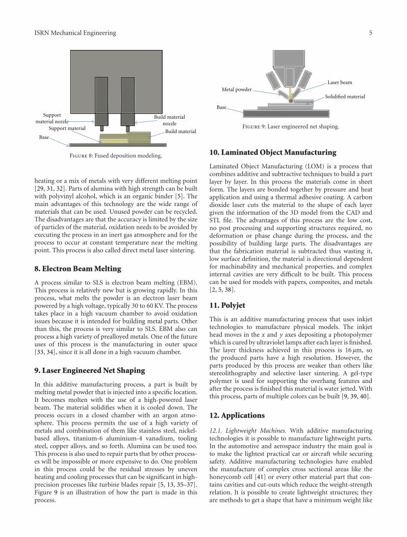
which is a medical grade PC. The main advantages of thisprocess are that no chemical post-processing required, noresins to cure, less expensive machine, and materials resultingin a more cost effective process [2, 5]. The disadvantages arethat the resolution on the z axis is low compared to otheradditive manufacturing process (0.25 mm), so if a smoothsurface is needed a finishing process is required and it is aslow process sometimes taking days to build large complexparts. To save time some models permit two modes; a fullydense mode and a sparse mode that save time but obviouslyreducing the mechanical properties [24]. In Figure 8 is shownthe basics fused deposition modeling process.
6. Prometal
Prometal is a three-dimensional printing process to buildinjection tools and dies. This is a powder-based process inwhich stainless steel is used. The printing process occurswhen a liquid binder is spurt out in jets to steel powder.The powder is located in a powder bed that is controlledby build pistons that lowers the bed when each layer isfinished and a feed piston that supply the material for eachlayer. After finishing, the residual powder must be removed.When building a mold no postprocessing is required. Ifa functional part is being built, sintering, infiltration, andfinishing processes are required [5, 11]. In the sinteringprocess, the part is heated to 350◦F for 24 hour hardeningthe binder fusing with the steel in a 60% porous specimen.In the infiltration process, the piece is infused with bronzepowder when they are heated together to more than 2000◦Fin an alloy of 60% stainless steel and 40% bronze [25–27].The same process, but with different sintering temperaturesand times, has been used with other materials like a tungstencarbide powder sintered with a zirconium copper alloy forthe manufacturing of rocket nozzles; these parts have betterproperties than CNC machined parts of the same material[28].
7. Selective Laser Sintering
This is a three-dimensional printing process in which apowder is sintered or fuses by the application of a carbondioxide laser beam. The chamber is heated to almost themelting point of the material. The laser fused the powderat a specific location for each layer specified by the design.The particles lie loosely in a bed, which is controlled bya piston, that is lowered the same amount of the layerthickness each time a layer is finished. This process offersa great variety of materials that could be used: plastics,metals, combination of metals, combinations of metals andpolymers, and combinations of metals and ceramics [13, 29,30]. Examples of the polymers that could be used are acrylicstyrene and polyamide (nylon), which show almost the samemechanical properties as the injected parts [29, 31]. It is alsopossible to use composites or reinforced polymers, that is,polyamide with fiberglass. They also could be reinforced withmetals like copper. For metals, a binder is necessary. Thiscould be a polymer binder, which will be later removed by
ISRN Mechanical Engineering 5
Supportmaterial nozzle
Support material
Base
Build materialnozzle
Build material
Figure 8: Fused deposition modeling.
heating or a mix of metals with very different melting point[29, 31, 32]. Parts of alumina with high strength can be builtwith polyvinyl alcohol, which is an organic binder [5]. Themain advantages of this technology are the wide range ofmaterials that can be used. Unused powder can be recycled.The disadvantages are that the accuracy is limited by the sizeof particles of the material, oxidation needs to be avoided byexecuting the process in an inert gas atmosphere and for theprocess to occur at constant temperature near the meltingpoint. This process is also called direct metal laser sintering.
8. Electron Beam Melting
A process similar to SLS is electron beam melting (EBM).This process is relatively new but is growing rapidly. In thisprocess, what melts the powder is an electron laser beampowered by a high voltage, typically 30 to 60 KV. The processtakes place in a high vacuum chamber to avoid oxidationissues because it is intended for building metal parts. Otherthan this, the process is very similar to SLS. EBM also canprocess a high variety of prealloyed metals. One of the futureuses of this process is the manufacturing in outer space[33, 34], since it is all done in a high vacuum chamber.
9. Laser Engineered Net Shaping
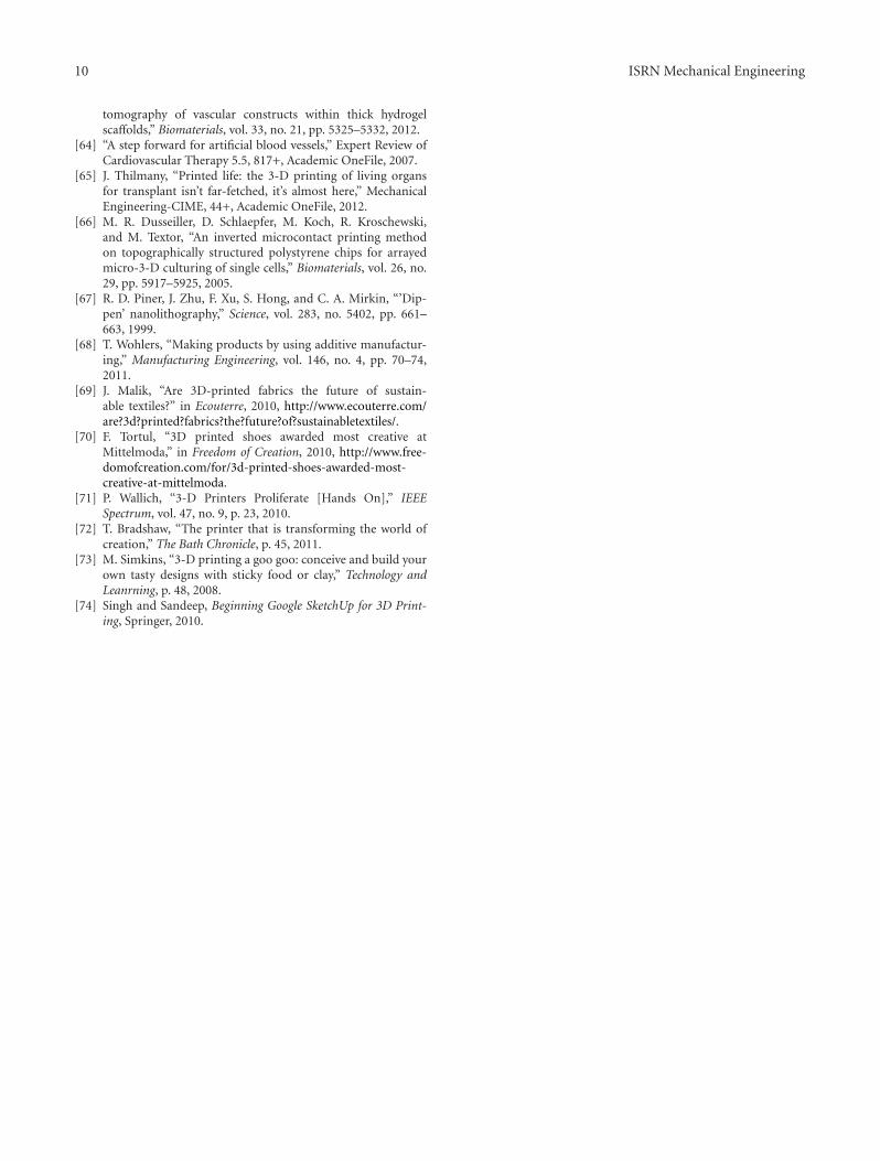
In this additive manufacturing process, a part is built bymelting metal powder that is injected into a specific location.It becomes molten with the use of a high-powered laserbeam. The material solidifies when it is cooled down. Theprocess occurs in a closed chamber with an argon atmo-sphere. This process permits the use of a high variety ofmetals and combination of them like stainless steel, nickel-based alloys, titanium-6 aluminium-4 vanadium, toolingsteel, copper alloys, and so forth. Alumina can be used too.This process is also used to repair parts that by other process-es will be impossible or more expensive to do. One problemin this process could be the residual stresses by unevenheating and cooling processes that can be significant in high-precision processes like turbine blades repair [5, 13, 35–37].Figure 9 is an illustration of how the part is made in thisprocess.
Base
Laser beam
Solidified materialMetal powder
Figure 9: Laser engineered net shaping.
10. Laminated Object Manufacturing
Laminated Object Manufacturing (LOM) is a process thatcombines additive and subtractive techniques to build a partlayer by layer. In this process the materials come in sheetform. The layers are bonded together by pressure and heatapplication and using a thermal adhesive coating. A carbondioxide laser cuts the material to the shape of each layergiven the information of the 3D model from the CAD andSTL file. The advantages of this process are the low cost,no post processing and supporting structures required, nodeformation or phase change during the process, and thepossibility of building large parts. The disadvantages arethat the fabrication material is subtracted thus wasting it,low surface definition, the material is directional dependentfor machinability and mechanical properties, and complexinternal cavities are very difficult to be built. This processcan be used for models with papers, composites, and metals[2, 5, 38].
11. Polyjet
This is an additive manufacturing process that uses inkjettechnologies to manufacture physical models. The inkjethead moves in the x and y axes depositing a photopolymerwhich is cured by ultraviolet lamps after each layer is finished.The layer thickness achieved in this process is 16 µm, sothe produced parts have a high resolution. However, theparts produced by this process are weaker than others likestereolithography and selective laser sintering. A gel-typepolymer is used for supporting the overhang features andafter the process is finished this material is water jetted. Withthis process, parts of multiple colors can be built [9, 39, 40].
12. Applications
12.1. Lightweight Machines. With additive manufacturingtechnologies it is possible to manufacture lightweight parts.In the automotive and aerospace industry the main goal isto make the lightest practical car or aircraft while securingsafety. Additive manufacturing technologies have enabledthe manufacture of complex cross sectional areas like thehoneycomb cell [41] or every other material part that con-tains cavities and cut-outs which reduce the weight-strengthrelation. It is possible to create lightweight structures; theyare methods to get a shape that have a minimum weight like

6 ISRN Mechanical Engineering
the hanging method and the soap film method [42]. Thehanging method and the soap fill method produce a verydifficult form of a structure which has been used for civilconstruction, but with additive manufacturing it is possibleto create structural parts for machines using the shapedescribed by these methods and reducing the total weight.Selective laser sintering, and electron beam are now usedin the aircraft and aerospace industries. Engineers performdesign within the manufacturing constrains but this processexpands the limits. With SLS and EBM, the limit will be theengineer’s imagination. They open a whole new dimensionof possible designs with almost any prealloyed metal powder[37]. With the traditional process these complex shapestructures will be expensive to do if at all possible. Withadditive manufacturing printing technologies like selectivelaser sintering or electron beam melting, hollow structures,which are less expensive than a solid one, can be made sinceless material is used.
12.2. Architectural Modeling. Creating an architecturalmodel can be very difficult for architects. Architects usuallybuild their models with hand techniques, but when complexmodels are on their minds making a physical model can be avery hard task. Modeling is very important for the architectsto study the models and their functionality. They are alsoneeded for architects to explain them to their customersand convince them to make the project a reality [43].Additive manufacturing technologies can provide architectsa very powerful tool for their business, by being able tocreate a physical model faster without worrying about thecomplexity of their design. It also achieves a better resolutionthan other processes used in architecture. Architects workwith CAD software, so there is no need for them to adaptto anything because the STL file is created from a CADfile. Stereolithography is a process very suitable for thearchitectural modeling because of the materials used and theprinting resolution [34–47].
12.3. Medical Applications. Additive manufacturing printingtechnologies have vast applications in the medical world.They are transforming the practice of medicine throughthe possibilities of making rapid prototypes and very highquality bone transplants and models of damaged bone ofthe patients for analysis. Additive manufacturing printingmethods permit to scan and build a physical model ofdefective bones from patients and give doctors a better ideaof what to expect and plan better the procedure, this willsave cost and time and help achieve a better result [48, 49].Bone transplants now can be done by printing them andadditive manufacturing methods make it possible to havea transplant that is practically identical to the original.Because of the limitless form or shape of what could bebuilt, doctors have the option to create a porous-controlledmaterial that will permit osteoconductivity or to create aprecise metal transplant identical to the original dependingon the bone to be replaced [50–52]. Characteristics ofthe transplants such as density, pore shape and size, andpore interconnectivity are important parameters that will
manipulate tissue ingrowth and mechanical properties of theimplant bone. The mechanical strength of these implants arethree to five times higher than others produced by otherprocesses and the possibility of inflammation caused bymicrodebris that breaks during the procedure is reduced[45]. Additive manufacturing is a very good tool for dentistsbecause they can easily build a plaster model of a patient’smouth or replace the teeth, which have a unique form withprocess like stereolithography, selective laser sintering andelectron beam melting [53–55].
According to PC Magazine [54], an 83-year-old Belgianwoman became the first-ever person to receive a transplantjawbone tailor-made for her face using a 3D printer and thesurgery time and recovery were a lot less than other patientsthat received the same procedure. The shapes of bones differtoo much between each person and additive manufacturingprinting produces transplants that fit better, and are easier toinsert and secure, reducing the time for the procedure andproduce a better cosmetic result [55, 56].
Stereolithography is being used to manufacture pros-thetic sockets. By using this technology to ensure that theform of the socket adapt better to the patient while beingmore cost-effective than hand or machined methods [57].Not only hard parts like bones can be produced, also it ispossible to print cells in a 3D array that with the possibilityof printing complex shapes and arrays human tissue can beprinted [58–61]. This technology will help patients that havelost tissue in accidents or from other reasons to recover fasterand with better cosmetic results. In addition 3D cell printingtechnologies offer the possibility of printing artificial bloodvessels that can be used in the coronary bypass surgery or anyother blood vessel procedure or diseases, like cardiovasculardefects and medical therapy [62–64]. The application of thisprinted blood vessels is in the future. Research in this area,also called bioprinting organs, will eventually lead to printedorgans, but this could take 20 years until someone achieves it[65].
Cell printing is not limited to print human tissue; itis also used in the field of molecular electronics. The pre-cision of high-resolution processes like nanolithographyand photolithography permits the creation of biochips andbiosensors [63, 66, 67].
12.4. Improving the Manufacturing of Fuel Cells. Additivemanufacturing technologies can be used in processes thatrequire a very precise thin film of a certain material. Inthe manufacture of polymer electrolyte membrane fuel cells(PEMFCs), it is necessary to precisely deposit a very thinlayer of platinum, needed for the oxidation and reductionreactions, with high utilization efficiency of the platinum.This could be critical for taking this technology to the masses.One of the other processes used is screen printing, but thisprocess is done by hand and compromises the uniformityand time efficiency. The process is greatly improved by usingthe 3D printing process to deposit the layer of platinum.In Figure 10, there is a comparison between the processes.The inkjet printing method is 4 to 5 times faster than screenprinting [15].

ISRN Mechanical Engineering 7
Screen printing
Gasdiffusion
layerPaint Dry Mass Desired
loadingYes
Electrode
No
Inject printing
Gasdiffusion
layerPrint
Desiredloading
YesElectrode
No
Figure 10: Screen printing compared to inkjet Printing [15].
12.5. Additive Manufacturing in Art. Additive manufacturingtechnologies are a very powerful tool to artist in the fashion,furniture, and lightning industry given the possibility ofvirtually manufacturing the most complex form imaginable.There are companies that manufacture furnishing comple-ments, lightning, and accessories including clothes using SLS[68–70].
12.6. Additive Manufacturing for Hobbyist. Additive manu-facturing technologies are reaching nonindustrial users. Thisrevolution started in 2007 with printers that could be as lowas $500 using a variant of the fused deposition modelingprocess. However, these low-cost printers are mostly soldas do-it-yourself (DIY) projects, so, technical ability on thepart of the users is required. However, these days withlarger companies entering the business 3D printers are closerto reaching the masses. At this time, plastics and ediblematerials like chocolate materials are only available [71–73].Users can use CAD software normally used by engineers.Easier ones for hobbyists are available which can be usedfor design. There are many apps that hobbyists can make 3Dmodels and print them using a 3D printer [74].
12.7. Strength Comparison. Studies have been made toanalyze the properties of the product in each process. Kimand Oh [16] compared the properties of nonmetal additivemanufacturing processes. They tested the specimens in thebuilding direction and perpendicular to the building direc-tion and they found very little influence in the buildingdirection in 3DP but an enormous influence in LOM [70].Figure 11 is a comparison of the strength for LOM, Polyjet,SL, SLS, FDM, and 3DP.
The strength of the material produced by Prometal, EBM,SLS, and LENS is compared in Figure 12. The studies weremade by [17–20].
13. Discussion and Conclusion
In this paper article is discussed the early versions of additivemanufacturing for making fast prototypes that was initiated
0 50 100
3DP
FDM
SLS
SL
Polyjet
LOM
Vertical strength (Mpa) Horizontal strength (Mpa)
Figure 11: Tensile strength of various 3D printing processes adapt-ed from [16].
by the necessity of speeding the process in model develop-ment and shortening the time between product developmentand market placement. Additive manufacturing processestake the information from a CAD file that is later convertedto an STL file. In this process, the drawing made in the CADsoftware is approximated by triangles and sliced containingthe information of each layer that is going to be printed.There is also a discussion of the relevant additive manu-facturing processes and their applications and a review ofhow the parts are made using these additive manufacturingprocesses. The continuous and increasing growth experi-enced since the early days and the successful results up todate, there is optimism that additive manufacturing has asignificant place in the future of manufacturing.

8 ISRN Mechanical Engineering
0 1000 2000
Ultimate strength (Mpa)Yield strength (Mpa)
LENS (316 stainless steel)
LENS (Ti-6Al-4V)
Prometal (420 stainless· · ·
EBM (Ti-6Al-4V)
SLS (steel/Cu-P/Ni powder)
Figure 12: Tensile strength of various 3D printing processes [17–20].
In 2004, the Society of Manufacturing Engineers did aclassification of the various technologies [11], but there areat least four additional significant technologies in 2012.
Additive manufacturing technologies have been wel-comed in the aerospace industry because of the possibilityto manufacture lighter structures to reduce weight, whichis the common goal of aircraft and spacecraft designers.In the automotive industry, additive manufacturing is ad-vantageous also in reproducing difficult-to-find parts, forexample, parts for classic cars. Additive manufacturing istransforming the practice of medicine; now it is possibleto have a precise model of a bone before a surgery andthe possibility of creating an accurate transplant, no matterhow complex its form is. Additive manufacturing is makingwork easier for architects, who now can print the 3D modelsof whatever complex shape for a civil project they have inmind. In addition, studies are reviewed which were aboutthe strength of products made in additive manufacturingprocesses. Review has been presented of studies consideringnonmetal material processes and metal material processes inwhich a comparison of strength of the products was madeby the various processes. However, there is still a lot of workand research to be accomplished before additive manufac-turing processes become the standard in the manufacturingindustry because not every commonly used manufacturingmaterial can be handled. The accuracy needs improvementto eliminate the necessity of a finishing process and to be ableto produce parts that require the highest levels of precision.
References
[1] S. Ashley, “Rapid prototyping systems,” Mechanical Engineer-ing, vol. 113, no. 4, p. 34, 1991.
[2] R. Noorani, Rapid Prototyping—Principles and Applications,John Wiley & Sons, 2006.
[3] J. Flowers and M. Moniz, “Rapid prototyping in technologyeducation,” Technology Teacher, vol. 62, no. 3, p. 7, 2002.
[4] C. K. Chua, S. M. Chou, S. C. Lin, K. H. Eu, and K. F. Lew,“Rapid prototyping assisted surgery planning,” InternationalJournal of Advanced Manufacturing Technology, vol. 14, no. 9,pp. 624–630, 1998.
[5] K. Cooper, Rapid Prototyping Technology, Marcel Dekker,2001.
[6] A. Kochan, “Rapid growth for rapid prototyping,” AssemblyAutomation, vol. 17, no. 3, pp. 215–217, 1997.
[7] T. Wohlers, Wohlers Report 2011, Wholers Associates, 2011.[8] T. Wohlers, “Additive Manufacturing Advances,” Manufactur-
ing Engineering, vol. 148, no. 4, pp. 55–56, 2012.[9] T. Wohlers, Wohlers Report 2010, Wholers Associates, 2010.
[10] T. Grimm, User’s Guide to Rapid Prototyping, Society ofManufacturing Engineers, 2004.
[11] P. P. Kruth, “Material incress manufacturing by rapid proto-typing techniques,” CIRP Annals—Manufacturing Technology,vol. 40, no. 2, pp. 603–614, 1991.
[12] T. Wohlers, Wohlers Report 2009, Wholers Associates, 2009.[13] J. W. Halloran, V. Tomeckova, S. Gentry et al., “Photopolymer-
ization of powder suspensions for shaping ceramics,” Journalof the European Ceramic Society, vol. 31, no. 14, pp. 2613–2619,2011.
[14] D. T. Pham and C. Ji, “Design for stereolithography,” Proceed-ings of the Institution of Mechanical Engineers, vol. 214, no. 5,pp. 635–640, 2000.
[15] A. D. Taylor, E. Y. Kim, V. P. Humes, J. Kizuka, and L. T.Thompson, “Inkjet printing of carbon supported platinum 3-D catalyst layers for use in fuel cells,” Journal of Power Sources,vol. 171, no. 1, pp. 101–106, 2007.
[16] G. D. Kim and Y. T. Oh, “A benchmark study on rapid pro-totyping processes and machines: quantitative comparisonsof mechanical properties, accuracy, roughness, speed, andmaterial cost,” Proceedings of the Institution of MechanicalEngineers, vol. 222, no. 2, pp. 201–215, 2008.
[17] J. P. Kruth, X. Wang, T. Laoui, and L. Froyen, “Lasers andmaterials in selective laser sintering,” Assembly Automation,vol. 23, no. 4, pp. 357–371, 2003.
[18] L. Facchini, E. Magalini, P. Robotti, and A. Molinari, “Micro-structure and mechanical properties of Ti-6Al-4V producedby electron beam melting of pre-alloyed powders,” RapidPrototyping Journal, vol. 15, no. 3, pp. 171–178, 2009.
[19] R. Shivpuri, X. Cheng, K. Agarwal, and S. Babu, “Evaluation of3D printing for dies in low volume forging of 7075 aluminumhelicopter parts,” Rapid Prototyping Journal, vol. 11, no. 5, pp.272–277, 2005.
[20] Y. Xiong, Investigation of the laser engineered net shapingprocess for nanostructured cermets [ProQuest Dissertations],University of California, 2009.
[21] H. Kim, C. Jae-Won, and R. Wicker, “Scheduling and processplanning for multiple material stereolithography,” Rapid Pro-totyping Journal, vol. 16, no. 4, pp. 232–240, 2010.
[22] M. Szilvœi-Nagy and G. Matyasi, “Analysis of STL files,”Mathematical and Computer Modelling, vol. 38, no. 7–9, pp.945–960, 2003.
[23] C. Iancu, D. Iancu, and A. Stamcioiu, “From Cad modelto 3D print via ”STL” file format,” http://www.utgjiu.ro/revmec/mecanica/pdf/2010-01/13 Catalin%20Iancu.pdf.
[24] S. Morvan, R. Hochsmann, and M. Sakamoto, “ProMetalRCT(TM) process for fabrication of complex sand molds andsand cores,” Rapid Prototyping, vol. 11, no. 2, pp. 1–7, 2005.

ISRN Mechanical Engineering 9
[25] R. C. T. ProMetal, “ProMetal RCT rapid prototyping anddigital sand casting services,” 2010, http://www.youtube.com/watch?v=Z8MaVaqNr3U.
[26] Ex One, “3D metal printing,” 2010, http://www.youtube.com/watch?v=i6Px6RSL9Ac&feature=related.
[27] D. W. Lipke, Y. Zhang, Y. Liu, B. C. Church, and K. H. Sand-hage, “Near net-shape/net-dimension ZrC/W-based compos-ites with complex geometries via rapid prototyping and dis-placive compensation of porosity,” Journal of the EuropeanCeramic Society, vol. 30, no. 11, pp. 2265–2277, 2010.
[28] J. P. Kruth, P. Mercelis, J. van Vaerenbergh, L. Froyen, and M.Rombouts, “Binding mechanisms in selective laser sinteringand selective laser melting,” Rapid Prototyping Journal, vol. 11,no. 1, pp. 26–36, 2005.
[29] T. Hwa-Hsing, C. Ming-Lu, and Y. Hsiao-Chuan, “Slurry-based selective laser sintering of polymer-coated ceramicpowders to fabricate high strength alumina parts,” Journal ofthe European Ceramic Society, vol. 31, no. 8, pp. 1383–1388,2011.
[30] G. V. Salmoria, R. A. Paggi, A. Lago, and V. E. Beal,“Microstructural and mechanical characterization of PA12/MWCNTs nanocomposite manufactured by selective lasersintering,” Polymer Testing, vol. 30, no. 6, pp. 611–615, 2011.
[31] D. Slavko and K. Matic, “Selective laser sintering of compositematerials technologies,” Annals of DAAAM & Proceedings, p.p1527, 2010.
[32] Technology Gateway, “NASA— EBF3—electron beam formfabrication,” 2009, http://www.youtube.com/watch?v=WrWHwHuWrzk.
[33] L. Murr, S. Gaytan, D. Ramirez et al., “Metal fabrication byadditive manufacturing using laser and electron beam meltingtechnologies,” Journal of Materials Science & Technology, vol.28, no. 1, pp. 1–14, 2012.
[34] C. Semetay, Laser engineered net shaping (LENS) modelingusing welding simulation concepts [ProQuest Dissertations andTheses], Lehigh University, 2007.
[35] Y. Xiong, Investigation of the laser engineered net shapingprocess for nanostructured cermets [ProQuest Dissertations andTheses], University of California, 2009.
[36] V. K. Balla, S. Bose, and A. Bandyopadhyay, “Processing ofbulk alumina ceramics using laser engineered net shaping,”International Journal of Applied Ceramic Technology, vol. 5, no.3, pp. 234–242, 2008.
[37] Y. S. Liao, H. C. Li, and Y. Y. Chiu, “Study of laminated objectmanufacturing with separately applied heating and pressing,”International Journal of Advanced Manufacturing Technology,vol. 27, no. 7-8, pp. 703–707, 2006.
[38] B. Vaupotic, M. Brezocnik, and J. Balic, “Use of PolyJettechnology in manufacture of new product,” Journal ofAchievements in Materials and Manufacturing Engineering, vol.18, no. 1-2, pp. 319–322, 2006.
[39] R. Singh, “Process capability study of polyjet printing for plas-tic components,” Journal of Mechanical Science and Technology,vol. 25, no. 4, pp. 1011–1015, 2011.
[40] V. Petrovic, J. Vicente, H. Gonzalez et al., “Additive lay-ered manufacturing: sectors of industrial application shownthrough case studies,” International Journal of ProductionResearch, vol. 49, no. 4, pp. 1061–1079, 2011.
[41] K. U. Bletzinger and E. Ramm, “Structural optimizationand form finding of light weight structures,” Computers andStructures, vol. 79, no. 22–25, pp. 2053–2062, 2001.
[42] A. Williams, “Architectural modelling as a form of research,”Architectural Research Quarterly, vol. 6, no. 4, pp. 337–347,2002.
[43] SweetOnionsCreations, “Architecture model and 3D print-ing—sweet onion creations,” 2007, http://www.youtube.com/watch?v=rEzugxybKmA.
[44] M. Phair, “Rapid prototyping: the next wave in architecturalmodeling,” Building Design & Construction, vol. 45, no. 11, pp.15–16, 2004.
[45] I. Gibson, T. Kvan, and W. Ling, “Rapid prototyping forarchitectural models,” Rapid Prototyping Journal, vol. 8, no. 2,pp. 91–99, 2002.
[46] J. Giannatsis, V. Dedoussis, and D. Karalekas, “Architecturalscale modelling using stereolithography,” Rapid PrototypingJournal, vol. 8, no. 3, pp. 200–207, 2002.
[47] F. Rengier, A. Mehndiratta, H. von Tengg-Kobligk et al., “3Dprinting based on imaging data: review of medical applica-tions,” International Journal of Computer Assisted Radiologyand Surgery, vol. 5, no. 4, pp. 335–341, 2010.
[48] W. J. James, M. A. Slabbekoorn, W. A. Edgin, and C. K.Hardin, “Correction of congenital malar hypoplasia usingstereolithography for presurgical planning,” Journal of Oraland Maxillofacial Surgery, vol. 56, no. 4, pp. 512–517, 1998.
[49] Chaput, Christophe, and J. B. Lafon, “Ceramic industry,” vol.161, no. 9, pp. 15–16, 2011.
[50] G. Fielding, A. Bandyopadhyay, and B. Susmita, “Effects ofsilica and zinc oxide doping on mechanical and biologicalproperties of 3D printed tricalcium phosphate tissue engineer-ing scaffolds,” Dental Materials, vol. 28, no. 2, pp. 113–122,2012.
[51] J. Suwanprateeb, R. Sanngam, W. Suvannapruk, and T.Panyathanmaporn, “Mechanical and in vitro performance ofapatite-wollastonite glass ceramic reinforced hydroxyapatitecomposite fabricated by 3D-printing,” Journal of MaterialsScience, vol. 20, no. 6, pp. 1281–1289, 2009.
[52] R. Makovec, “Digital technologies in dental laboratories,”Annals of DAAAM & Proceedings, p. p1579, 2010.
[53] R. van Noort, “The future of dental devices is digital,” DentalMaterials, vol. 28, no. 1, pp. 3–12, 2012.
[54] A. Moscaritolo, “Woman receives 3D printer? created trans-plant Jaw,” PC Magazine Online, 2012, http://www.pcmag.com/article2/0,2817,2399887,00.asp.
[55] S. J. Hollister, “Porous scaffold design for tissue engineering,”Nature Materials, vol. 4, no. 7, pp. 518–524, 2005.
[56] M. A. Stoodley, J. R. Abbott, and D. A. Simpson, “Titaniumcranioplasty using 3-D computer modelling of skull defects,”Journal of Clinical Neuroscience, vol. 3, no. 2, pp. 149–155,1996.
[57] N. Herbert, D. Simpson, W. D. Spence, and W. Ion, “A pre-liminary investigation into the development of 3-D printingof prosthetic sockets,” Journal of Rehabilitation Research andDevelopment, vol. 42, no. 2, pp. 141–146, 2005.
[58] B. Christensen, “New device prints human tissue,” 2009,http://www.livescience.com/5977-device-prints-human-tis-sue.html.
[59] T. Qian and Y. Wang, “Micro/nano-fabrication technologiesfor cell biology,” Medical and Biological Engineering andComputing, vol. 48, no. 10, pp. 1023–1032, 2010.
[60] S. J. Song, J. Choi, Y. D. Park et al., “Sodium alginate hydrogel-based bioprinting using a novel multinozzle bioprintingsystem,” Artificial Organs, vol. 35, no. 11, pp. 1132–1136, 2011.
[61] V. Mironov, N. Reis, and B. Derby, “Bioprinting: a beginning,”Tissue Engineering, vol. 12, no. 4, pp. 631–634, 2006.
[62] M. Conner, “3-D medical printer to print body parts,” EDN,vol. 55, no. 3, p. 9, 2010.
[63] L. Zhao, V. Lee, S. Yoo, G. Dai, and X. Intes, “The integrationof 3-D cell printing and mesoscopic fluorescence molecular
10 ISRN Mechanical Engineering
tomography of vascular constructs within thick hydrogelscaffolds,” Biomaterials, vol. 33, no. 21, pp. 5325–5332, 2012.
[64] “A step forward for artificial blood vessels,” Expert Review ofCardiovascular Therapy 5.5, 817+, Academic OneFile, 2007.
[65] J. Thilmany, “Printed life: the 3-D printing of living organsfor transplant isn’t far-fetched, it’s almost here,” MechanicalEngineering-CIME, 44+, Academic OneFile, 2012.
[66] M. R. Dusseiller, D. Schlaepfer, M. Koch, R. Kroschewski,and M. Textor, “An inverted microcontact printing methodon topographically structured polystyrene chips for arrayedmicro-3-D culturing of single cells,” Biomaterials, vol. 26, no.29, pp. 5917–5925, 2005.
[67] R. D. Piner, J. Zhu, F. Xu, S. Hong, and C. A. Mirkin, “’Dip-pen’ nanolithography,” Science, vol. 283, no. 5402, pp. 661–663, 1999.
[68] T. Wohlers, “Making products by using additive manufactur-ing,” Manufacturing Engineering, vol. 146, no. 4, pp. 70–74,2011.
[69] J. Malik, “Are 3D-printed fabrics the future of sustain-able textiles?” in Ecouterre, 2010, http://www.ecouterre.com/are?3d?printed?fabrics?the?future?of?sustainabletextiles/.
[70] F. Tortul, “3D printed shoes awarded most creative atMittelmoda,” in Freedom of Creation, 2010, http://www.free-domofcreation.com/for/3d-printed-shoes-awarded-most-creative-at-mittelmoda.
[71] P. Wallich, “3-D Printers Proliferate [Hands On],” IEEESpectrum, vol. 47, no. 9, p. 23, 2010.
[72] T. Bradshaw, “The printer that is transforming the world ofcreation,” The Bath Chronicle, p. 45, 2011.
[73] M. Simkins, “3-D printing a goo goo: conceive and build yourown tasty designs with sticky food or clay,” Technology andLeanrning, p. 48, 2008.
[74] Singh and Sandeep, Beginning Google SketchUp for 3D Print-ing, Springer, 2010.

International Journal of
AerospaceEngineeringHindawi Publishing Corporationhttp://www.hindawi.com Volume 2010
RoboticsJournal of
Hindawi Publishing Corporationhttp://www.hindawi.com Volume 2014
Hindawi Publishing Corporationhttp://www.hindawi.com Volume 2014
Active and Passive Electronic Components
Control Scienceand Engineering
Journal of
Hindawi Publishing Corporationhttp://www.hindawi.com Volume 2014
International Journal of
RotatingMachinery
Hindawi Publishing Corporationhttp://www.hindawi.com Volume 2014
Hindawi Publishing Corporation http://www.hindawi.com
Journal ofEngineeringVolume 2014
Submit your manuscripts athttp://www.hindawi.com
VLSI Design
Hindawi Publishing Corporationhttp://www.hindawi.com Volume 2014
Hindawi Publishing Corporationhttp://www.hindawi.com Volume 2014
Shock and Vibration
Hindawi Publishing Corporationhttp://www.hindawi.com Volume 2014
Civil EngineeringAdvances in
Acoustics and VibrationAdvances in
Hindawi Publishing Corporationhttp://www.hindawi.com Volume 2014
Hindawi Publishing Corporationhttp://www.hindawi.com Volume 2014
Electrical and Computer Engineering
Journal of
Advances inOptoElectronics
Hindawi Publishing Corporation http://www.hindawi.com
Volume 2014
The Scientific World JournalHindawi Publishing Corporation http://www.hindawi.com Volume 2014
SensorsJournal of
Hindawi Publishing Corporationhttp://www.hindawi.com Volume 2014
Modelling & Simulation in EngineeringHindawi Publishing Corporation http://www.hindawi.com Volume 2014
Hindawi Publishing Corporationhttp://www.hindawi.com Volume 2014
Chemical EngineeringInternational Journal of Antennas and
Propagation
International Journal of
Hindawi Publishing Corporationhttp://www.hindawi.com Volume 2014
Hindawi Publishing Corporationhttp://www.hindawi.com Volume 2014
Navigation and Observation
International Journal of
Hindawi Publishing Corporationhttp://www.hindawi.com Volume 2014
DistributedSensor Networks
International Journal of


