
REDESIGN AND COMPARISON OF STEEL IN THE DOME OF THE
AUDITORIUM AT THE UNIVERSITY OF ILLINOIS
BY
GEORGE EDWARD M°INTYRE
HARRY LLEWELLYN FOSTER
THESIS
FOR
DEGREE OF BACHELOR OF SCIENCE
ARCHITECTURAL ENGINEERING
COLLEGE OF ENGINEERING
UNIVERSITY OF ILLINOIS
1913

UNIVERSITY OF ILLINOIS
May 2 5 t h . 1913
THIS IS TO CERTIFY THAT THE THESIS PREPARED UNDER MY SUPERVISION BY
G eorge Edward M cIn tyre and H arry L le w e lly n F o s te r ..............................
ENTITLED R ed esign , and Compa r is o n o f S t e e l in th e Dome o f th e
A u d itoriu m o f the U n iy e r s i t y p f l l l i n o i s . ...
IS APPROVED BY ME AS FULFILLING THIS PART OF THE REQUIREMENTS FOR THE
DEGREE OF B a c h e lo r o f S c ie n c e in A r c h it e c t u r a l E n g in e e r in g
3 4 7 4 1 r»

TABLE OF CONTENTS.
I . Introfiuction Page i
I I . Number o f Trusses and Spacing ft 2
I I I . C alculation o f Loads ft 3
IV . E xp lan ation o f Drawings t! 6
V. E xp lan ation o f Stress and Tabulation Sheets 11 7
V I. Tabulation o f Proposed System it 8
V II. Tabulation o f Present System it 11
V III . Conclusions tt 21
IX. Drawings

1 .
I .
REDESIGN AND COMPARISON OF STEEL IN THE DOIiE
LLINOIS.
The Auditorium at the U niversity c f I l l in o is ,e r e c te d
OF THE
AUDITORIUM AT THE UNIVERSITY OF IL!
in 19CO is in general ou tlin e somewhat s im ilia r to the Pantheon
a* -om e.lt is a brick and stee l structure,the main body o f which
i s c ircu la r with a diameter o f one hundred and twenty feet and
- height o f one hundred and eleven fe e t .
The dome surmounting the central feature i s supported
oy txiirty s ix trusses o f s ix d iffe ren t types.These in turn are
carr ied by fourteen columns which extend to the foundations.The
center o f the dome ca rr ies a low lantern under which is located
a sk y -ligh t.A s the construction o f the lantern i s very simple no
changes were thought necessary in it ,th e r e fo r e i t ’ s weight need
not be considered except as t o . i t ' s a ffe c t upon the stresses in
the tru sses .
" •~® purpose o f th is th es is was to design , i f p03sible>
a system o f trusses which would span the entire bu ild ing and
1 9 di rec t l y on tne e x ter io r w alls thus making i t unnecessry to
provide columns fo r th e ir support except at the front o f the
bu ild in g where no bearing wall is a v a ila b le . While there is
some disadvantages in the use o f long trusses owing to the fact
that the members required are rather la r g e ,it seemed upon in
v e s tig a tion that th is would be more than o f fs e t by th e ir sim
p l i c i t y , ease o f erection and r ig id ity o f the whole when erected .

2.
Then too ;b y using long trusses the ex te r io r w alls,which are
e n t ire ly adquate fo r that purpose can he used a3 supports thus
making the use o f columns unnecessary.
A fter considering the problem at length i t was decid
ed that trusses o f ine hundred and twenty foot span and so mod
i f i e d as to reta in the contour o f the ex terior and in te r io r sh e lls
o f tire dome would be the best solu tion o f the problem. The cres
cent truss has the advantages o f low stresses in the web members,
transm its very l i t t l e outward thrust to the supports and makes
the domed ce ilin g e ffe c t p o ss ib le . Also i t provides a ready means
o f support for the suspended c e i l in g .
In order to avoid obstructing the sky -ligh t area under
the lantern i t was found necessary to omit the upper chord members
o f the tru sses at that point and substitu te in th e ir p lace a poly
gonal compression ring which would serve the same purpose but leave
the opening unobstructed. The low er chord members were run d ire ct
ly through to support the sky-ligh t in addition to th e ir function
in the tru ss ,
I I . NUMBER OF TRUSSES AND SPACING
In the choice o f the number o f trusses to be used i t
was decided that nine fu ll trusses would give the best r e su lts .
With th is arrangement the maximum spacing at the perim eter o f the
bu ild in g i s approximately twenty one fast while the longest
p u rlin s are twenty fe e t . This arrangement gives purlins which can
be econom ically constructed from single r o lle d shapes.

9o «
In designing the purlins account was taken o f the normal load
on ly ,th e thrust p a ra lle l to the ro o f being taken by sag rods
and the roo f covering which is t in on 7/8inch sheathing la id
diagonally to the r a fte r s ,
I I I . CALCULATION OF LOADS
Owing to the fact that the loads used in the o r ig in a l
design were not obtainable and that the purpose o f th is th e s is
i s to compare with the o ld system as w ell as to design a new one
, i t was necessary to ca lcu la te the to ta l dome load used. This was
done by making a solu tion o f the present system ,and by compar
ing the stresses obtained with those used in i t s design ,a fa ct
or was gotton by which the t o ta l load could be ca lcu la ted . This
load proved to be three hundred and th irteen tons on the en tire
dome or seventeen and one h a lf tons on each o f the eighteen h a lf
trusses o f the proposed system. In order to know the d is t r i -
butaticn o f the loads on the tr u s s e s , ca lcu la tion s were made as
fe llo w s : -
Wind Lcad-
A maximum wind load o f th ir ty pounds per square foot
on a v e r t ica l surface was assumed. This was reduced to i t s component normal to the ro o f by the straight l in e method; see
drawing number one,sheet four. Owing to the fact that the cover
ing o f the dome is t in and the sheathing i s la id giagonal to the
ra fte rs ,y e ,fo llo w in g the p ra ctice o f the best a u th orities on th is
subject,assumed that only the v e r t ic a l component o f the wind load
would cause stresses in the tru sses ,th e h orizon ta l component ^eing
taken by the ro o f covering.

' .
The normal loads as determined by the method mentioned above
were then resolved into th e ir v e r t ica l and h orizonta l components
by graphical methods which are illu s tra te d on drawing number one sheet
four. In determining the wind load on the roo f a maximum wind
pressure o f th ir ty pounds per square foot on a v e r t ica l surface
was assumed , ’out where the ro o f made an angle o f fo r ty -f iv e or
more degrees with the horizonta l the fu ll th ir ty pounds p9r s
square foot o f roo f was taken.
Snow Load-
In regard to snow load there is much d ifferen ce of
op in ion between engineers as to the proper va.lua to use how
ever a ll agree that i t i s never a maximum with maximum wind
lo a d . The lo c a l i t y in which a build ing i s to be erected in -
flunces the amount o f snow load and i t was decided to taka the
minimum amount as given in tab les based on the actual snow f a l l
in the lo c a l i t y o f Champaign for a period o f years. This amount
was ten pounds per square foot o f horizonta l p ro je c tio n o f the
r o o f and for ease in ca lcu la tion i t was reduced to i t s value
per square foot o f r o o f surface by cosin es. This gave a snow
load o f seven and one h a lf pounds per square foot o f ro o f
surface
Dead Load-
In arriv ing at the dead loads for a prelim inary de
sign i t i s the custom to take the weights o f the d ifferen t mater
i a l s from ta b les based on th e ir weights in trusses that have
a ctu a lly been b u ilt rather than to ca lcu la te the weight o f those
o f the truss in hand.
In th is problem the weights were : T in ,ten pounds per square
foot,sheath ing three pounds per square fo o t ,r a fte r s four rounds
per square foot .The purlins were designed to support the above
load s and th e ir actual weight determined.
Weight o f Trusses:
In ca lcu la tin g the weight o f the s te e l in the trusses
the best methods ava ilab le are l i t t l e more than rough approxi
m ations, There i s no doubt but that i t i s dependent on the span_1 jl!
and the area supported therefore the formula T = 25 - 13600 was
used in which W *“ weight o f truss per square foot o f area cover
ed,and 1 = the span o f the truss in fe e t . Taking the value o f 1 —
120 f e a t ■,W — 6.2 pounds per square foct o f area covered or 5.5
pounds per square foot o f ro o f surface .
Areas Supported At Panel Points:
The upper chord was divided into seven panels,each
seven feat nine inches in length . By m ultiplying the length
o f the purlins by seven feet nine inches the area support
ed at any panel was found. The t o ta l load on any panel was then
fonnd by m ultiplying the area supported at that point by the
values per square foot o f the d iffe re n t loads as was previously
determined. The loads thus obtained were without a doubt correct
and in ordinary p ra ctice would have been used,but as stated be
fore i t was the purpose o f the w riters to use the same loads as
were used in -the o r ig in a l design , consequently the to ta l load on
one h a lf o f a truss wa3 found and m ultip lied by eighteen to get
the en tire dome load .

!
6 .This was found to be somewhat below the o r ig in a l load ,so four
hundred and f i f t y pounds were added to the ca lcu lated loads at
each panel point making a to ta l load on each h a lf truss o f seven
teen and one h a lf tons and a t o ta l dome load o f three hundred
and th irteen ton s . This was,as nearly as could he ca lcu lated ..the
load used in the o r ig in a l design.
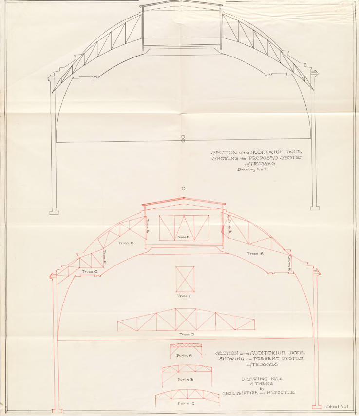
IV. E xp lan ation o f Drawings:
For convenience o f comparison and to i l lu s t r a te the
methods used in solving the stresses in the proposed system ,five
sheets o f drawings are appended. Sheet number one shows section s
through the dome in which drawing number one i s the ou tlin e o f
the proposed system and drawing number two i s an ou tlin e o f the
present system. Sheet number two shows the proposed system in
p lan . Sheet number three i s a plan o f the present system. Sheet
number four , drawing number one,shows the graphical methods used
in determining the v e r t ic a l wind load;drawing number two on the
same sheet sriows the stress diagram o f the graphical so lu tion o f
the tru ss and drawing number three shows the so lu tion o f the
s tre ss in the members o f the compression r in g . On sheet number
f iv e are presented several sc ale--drawings to i l lu s t r a te the
con stru ction o f the tru sses and the compression rin g .
7.
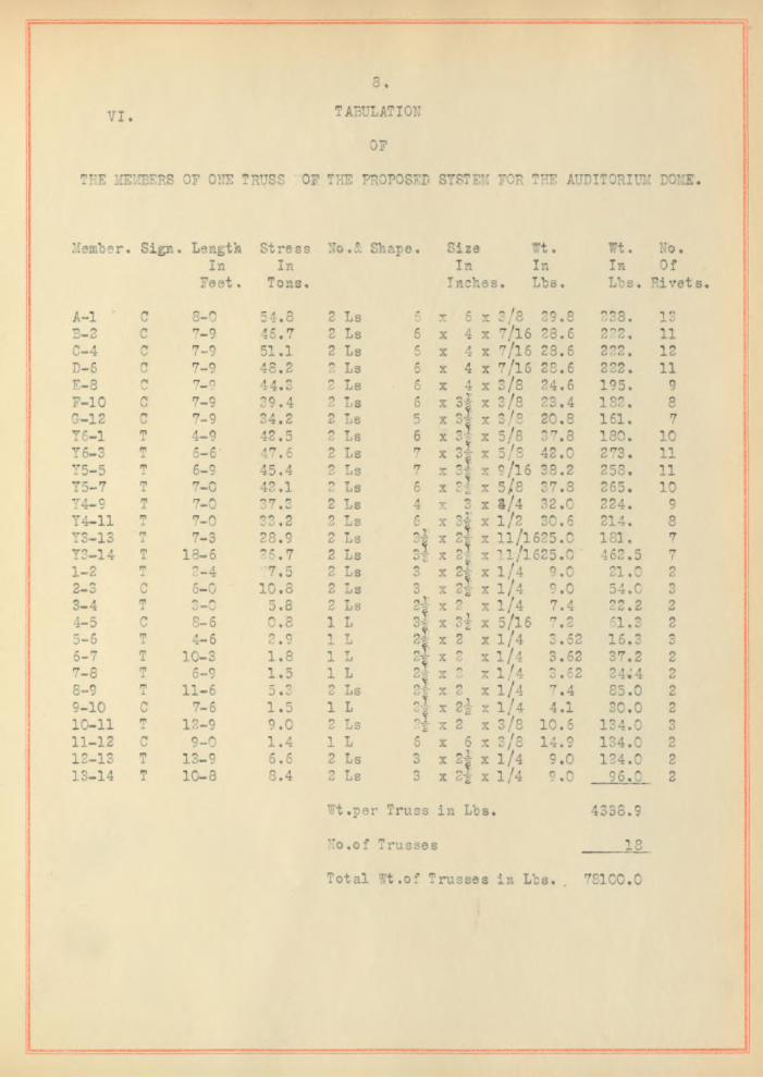
V. Explaination o f Stress and Tabulation Sheets:
In designing the members o f the proposed system the
ta b le s in R ick er ’ s "Design and Construction o f Roofs" were used
though a few check ca lcu la tion s were made by the l / r method. On
pages e ig h t#nine and ten are l i s t e d the members th e ir s ize , stress
and weight and the t o ta l weight o f the en tire system.
In gettin g the weights o f members o f the present
supporting system ,b lue pfcints o f the same ware obtained from the
o f f i c e o f the Supervising A rchitect and weights o f the d ifferen t
members l is t e d on pages eleven to twenty in c lu s iv e .
8
V I. TABULATION
OF
THE MEMBERS OF ONE TRUSS OF THE PROPOSED SYSTEM FOR THE AUDITORIUM DOME.
Member. Sign. Length Stress No,£ Shape. Size In In
Feet, Tons,
f t . In In
Inches. Lbs.
f t . No.In Of Lbs. R ivets,
A -l C 8-0 54,8 2 Ls 6 X 6 v 2/8 29.8 238. IS3-2 C 7-9 46.7 2 Ls 6 X 4 X 7/ 16 28.6 222. 11C-4 /*!U 7-9 51.1 2 Ls 5 X 4 X 7/ 16 23.6 222. 12D-6 c 7-9 48.2 2 Ls 6 X 4 X 7/16 28.6 222. 11E-S r» 7-0 44.3 2 Ls C.0 X 4 X 3/8 24.6 195. 9F-10 C 7-9 39.4 2 Ls 6 X 4
3f 3 2
X 2/8 23.4 182. 80-12 c 7-9 34.2 2 Ls 5 X X 3 /8 20.8 161. 7Y6-1 rp1 4-9 42.5 2 Ls 6 X X 5/8 37.8 180. 10Y 6-3 T 6 -6 1 47,6 2 Ls 7 X «■* I0 g X 5/8
9/1642.0 273. 11
Y5-5 6-8 45.4 2 Ls 7 X <5 r; ! *-'■ 2
X 38.2 258. 11Y5-7 T 7-0 42.1 o6 Ls 6 X X 5/8 37.8 265. 10Y4-9 T 7-0 37.3 2 Ls 4 X 3 X a/4 32,0 224. 9Y4-11 T 7-0 OO 0vU « <6 2 Ls 6 X 1
ni2-1
X 1 /2 30.6 214. 8Y3-13 m1 7-3 28.9 2 Ls o l
3iX X 11/1625.0
l l / l 625.0181. 7
Y3-14 T 13-6 36.7 2 Ls X X 462.5 71-2 mJL 2-4 7.5 2 Ls X 2-1-
&X 1 /4 9.0 21.0 2
2-3 C 6-0 10.8 2 Ls 3 X X i / 4 9.0 54.0 33-4 T vJ —O 5.8 2 Ls s i X 2 X 1 /4 7.4 22.2 24-5 no 8-6 0 .8 1 L X i
°2 X 5/16 7.2 61.3 25-6 T 4-6 2.9 1 L 4 X 2 X 1 /4 «62 16,36-7 T 10-3 1.8 1 L X r*<3. X i / 4 3.62 37.2 27-8 T 6-9 1 .5 1 L
4X o X 1 /4 3.62 24;4 2
8-8 rn1 11-6 D « v! 2 Ls X nC X 1 /4 7.4 85.0 28-10 c 7-6 1 .5 1 L '-2 X 2| X 1 /4 4.1 30.0 210-11 T 12-9 9.0 2 Ls nJL;; 2 X 2 X 3/8 10.6 134.0 311-12 C 9-0 1 .4 1 L 5 X 6 X 3/8 14.8 134.0 212-13 T 13-9 6.6 2 Ls 3 X 15 JL
4X 1/4 9.0 124.0 2
13-14 T 10-8 8.4 2 Ls 3 X X 1 /4 9.0 96 .C 2
f t .per Truss in Lbs.
N o,of Trusses
4338.8
Total f t .o f Trusses in Lbs. . 781C0.C
9
TABULATION
OF
COLUMN WEIGHTS FOR THE PROPOSED SYSTEM FOR THE AUDITORIUM DOME.
I'Tuiii'bsr 5; Shape.Size in Inches. Length. f t . /F t . Wt.
2 Channels 7 54-0 19.5 1052.0
26. Lattice Bars. 1-0 1.5 39.0
T ota l Wt. per C ol. 1091.C
No. o f C ols. 4
Total Wt. in Lbs. 42 64.0

1C
TABULATION
o f
PURLINS FOR THE PROPOSED SYSTEM FOR THE AUDITORIUM DOME.
Shape £ Number, Size in Inches. Length, f t . /F t , Wt.
18 Is 6 17-0 12.25 3746.0
18 Is 5 15-0 9.75 2630.0
18 Is 4 13-0 9.5 2230.0
18 Is 4 11-0 7.5 1485.0
18 Is 3 9-0 6.5 1052.0
4 Is 6 20-6 12.25 1004.0
2 Is 5 21-6 12.25 527.0
1 I 6 21-9 12.25 268.0
Total f t . o f Purlins in Lbs. 12942.0
Total ¥ t. o f Purlins in Tons, 6.47
TABULATION
o f
TOTAL WEIGHTS OF STEEL IN THE PROPOSED SYSTEM FOR THE AUDITORIUM DOME".
Total Weight o f Trusses in Lbs. 78,100.0
Weight o f Connections. (20 foOf Wt. Of T russes.) 15,620.0
Total Wt. o f Purlins 12,942,0
Total Wt. o f Columns 4 .364.0
Total Wt. in Lbs. 111,026.0
Total Wt. in Tons 55.51
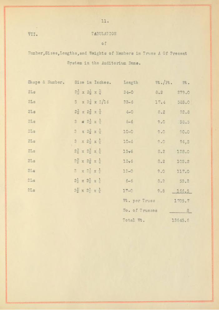
11
V II. TABULATION
o f
Number,Sizes,Lengths,and Weights o f Members in Truss A Of Present
System in the Auditorium Dome.
Shape & Number, Size in Inches. Length W t./P t, f t .
2Ls ol X 2i x i 34-0 3.2 279.0
2Ls 5 X s i x 5/16 33-6 17.4 583.0
2Ls 2 X 2 i x i 4-0 8.2 32.8
2Ls 3 * 2} x i 6-6 9.0 58.5
2Ls *3o X 2 i x i 10-0 9.0 80.0
2Ls 3r
X 2 i x i 10-6 9.0 94,5
2Ls 2 i X 2| x 1 1 5 t 6 8.2 128.0
2Ls 2| X 2f X j 12t 6 8.2 103.2
2Ls (ji X n_l 2 X i 1 " -0X <■’ *" ••. 9.0 117.0
2Ls 2| X 2i 1X 4 6-6 8.2 53.2
2Ls 3 l X 2| v 1X 4 17-0 9.8 166.5
Wt. per Truss 1705.7
No. o f Trusses 8
Total Wt. 13645.6
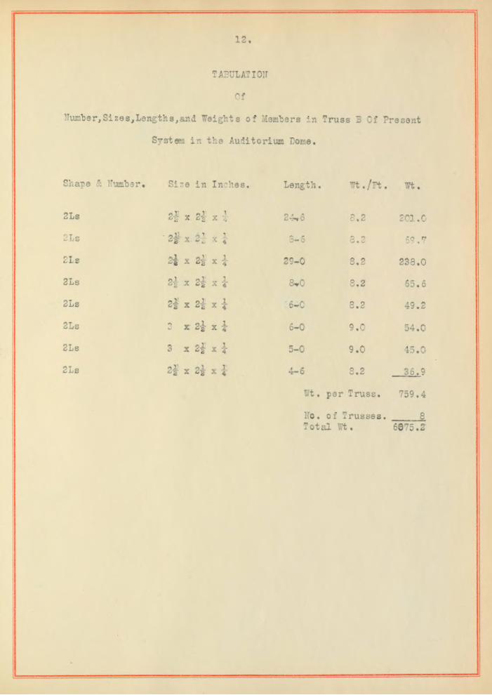
TABULATION
Of
Number,Sizes,Lengths,and Weights o f Members in Truss B Of Present
System in the Auditorium Dome,
Shape & Number# Si:- 9 in Inches. Length. Wt. /F t . Wt.
2Ls 2| X 2-1 X 4 24* 6 3.2 2 C1 . 0
2Ls - 9II X o T.* OlX 4 8-6 3.2 69,0
2Ls X 2* x i 29-0 3.2 238.0
2Ls X 2t x i 8*0 8 . 2 65.6
2Ls s i X 2| X | 6 - 0 8.2 49.2
2Ls X 2i x i 6 - 0 9.0 54.0
2Ls 3 X 2 f X 4 5-0 9.0 45.0
2Ls °2 X 2i X 4 4-6 8.2 36.9
f t . per Truss. 759.4
No. o f T russes. T ota l Wt.
86075.2

13
TABULATION
o f
Number,Size s,Lengths,and Weights o f Members in Truss C o f Present
System in the Auditorium Dome.
Shape 5: Number. S ize in Ineke
2Ls 9J.o 2 X 2 1 X 14
2Ls 3 X 2 i X 14
2Ls H X 2 | X 14
2Ls 2 -| X 2 | X 14*
2Ls 2| X -5.1: X JL4
2Ls 3 X X 14
2Ls 2 8' X 2| X 14
2Ls oj?C2r X 2i : X 14
2Ls 2 l X 2-1 X 14
Length. Wt. /F t . f t .
oo-u 8.2 189.0
24-0 ?.Q 216.0
5-0 8.2 41.0
4-0 8.2 32.8
5-0 8.2 41.0
4-0 9.0 36.0
6-6 8.2 53 .S
6-0 8.2 49.2
8-0 8.2 e5_sii*r. mt ,per Truss 723.9
No. o f 7 russes 8
Tot c±l- Wt. 5791.2

i
’ lumber
Shape
2Ls
2Ls
4Ls
4Ls
4Ls
4Ls
4Ls
4Ls
4Ls
4Ls
14.
TABULATION
o f
jSizes,Lengths,and Weights o f Members in Truss D o f Present
System in the Auditorium Dome.
Length. Wt. /F t . Wt.& Number. S ize , in Inches.
5 x 3|- x 3/8
5 x x 5 /l6
Six 2| x 5 /l6
2}x 2} x i
3|x 3 x 3/8
2|x 2| x
3 x 2| x -J
3 x 2| x tpi: v ll
- 2 X ^ 2 x 4
3|x 2-f ' x |
62-0 20.8 1290.0
63-0 17.4 1095.0
9-6 24.4 232.0
6-0 16.4 98.5
11-6 15.8 182.0
8-0 16 .4 131.0
12-0 18.0 216.0
9-6 18.0 171.0
12-6 16.4 205.0
11-0 19.6 216.0
Wt.per Truss 3836.5
O**O£3 T russes 4
Total Wt. 14346.0
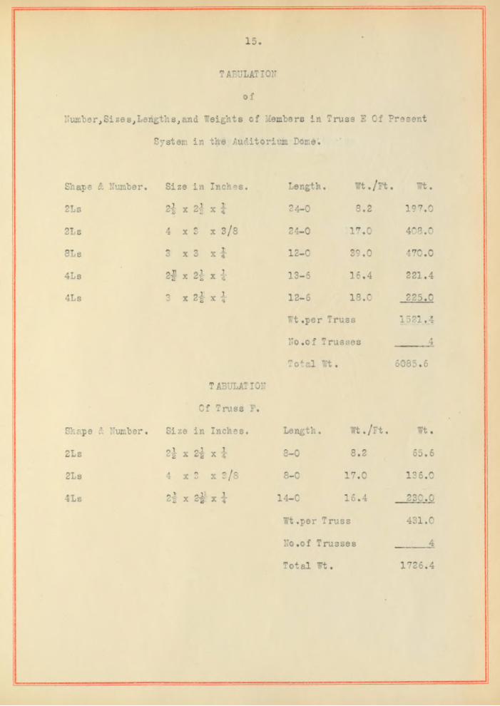
15
tabulation
o f
Number,Sizes,Lengths,and Weights o f Members in Truss E Of Present
System in the Auditorium Dome.
Shape & Number. Size in Inches, Length. w t ./p t . Wt.
2Ls 2-1 X * X 4 24-0 8 . 2 197.0
2Ls 4 x x 3 /8 24-0 17.0 408.0
SLs 3 x 3 X £ X 4 12-0 39.0 470.0
4Ls 2| x z l X 1 13-5 16.4 221.4
4Ls 3 x 2 2 X 1 12-6 18.0 225.0
W t.per Truss 1521.4
No .o f Trusses 4
Total Wt. 6085.6
TADULATION
Cf Truss F.
Shape Number. Si ze in Inches. Length. W t./F t. Wt,
2Ls 2 } x 2 i x ! 8 - 0 8.2 65.6
2Ls 4 x x 2 /8 8 - 0 17.0 136.0
4Ls - 12 f x 2| x i 14-0 16 .4 230.0
Wt .per Truss 431.0
No .o f Trusses 4
Total Wt. 1726.4

1 6 .
TABULATION .
o f
Number,Sizes,Lengths,and Weights o f Members in Purlin A o f Present
System in the Auditorium Dome.
Shape Si Number.Size in Inches. Length. f t . / F t . Wt.
2Ls 2$ x 2}x 14-0 8.2 115.0
2Ls 2f H x 15-0 8.2 123.0
4Ls 2f x Sj x 1 5-0 16.4 82.0
16 Bars L attice 2-0 1.25 40.0
Wt.per Purlin 360.6
No. o f Pu:’l ln s 8
Total Wt. 2880.0
TABULATION
Of Purlin B.
Shape Si Number. Size in Inches. Length. Wt. /F t . Wt.
2Ls Pl „ pi y 1122-0 8.2 180 .C
2Ls 2 x 2|- x 4 PA A<0 ■xmm v‘ 9.0 216.0
2Ls 2-} x 2 { x ’ | 9-0 8.2 7 3 . 7
4Ls 3 x. 2f x ' l 4-0 18-0 72.0
4Ls e l v a-J x i 4—0 16.4 65.6
4Ls 2-g x 2| X >; 2-0 16.4 49.2
4Ls 2| x 2-1 x 1 4-9 16.4 7 7 . 9
Wt. per P urlin . 734.4
No. o f P u rlin s. 8
T ot al Wt. 5875.2

17
Tabulation
o f
Number,Sizes,Lengths,and Weights o f Members in Purlin C o f Present
System in the Auditorium Dome.
Shape iq Number, Sizes in Inches, Length. f t . /F t . Wt.
2Ls 21 X 2 i x i 28-6 8.2 234.0
2Ls 1D'z X 2| x i 32-0 9.8 314.0
2Ls 2 i X 2-1 x i 7-0 8.2 57.3
4Ls 3 X 2t x i 4-6 18.0 31.0
4Ls 2 f X 2 i x 4-X 4 4-6 16.4 73.9
4Ls 2| X 21 x i 4-0 16 .4 65.7
4Ls 2-1 X«-v_l^ 2 x i 5-6 16.4 90.4
4Ls 2 f X 2l X i 5-6 15.4 90.4
2Ls 2| X 21- x 4 4-6
Wt, per
8.2
Purlin
35.8
1043.0
No. o f Purlins 8
Total f t • 8348.8
TABULATION
Of Purlin D«
Shape t Number. Size in Inches Length. f t . /F t . I t ,
20 Channels r0 8-0 8.0 1280.0

13
TABULATION
of-
Number,Sizes,Lengths,and Weights o f Members in Purlin E o f Present
System in the Auditorium Dome.
Shape & Number. Size in Inches, Length , Wt., /F t . wt. ■
2Ls X 2 i x 5/16 3-6 12,,2 102.7
2Ls 2-J x 2 i x i 9-0 8,,2 73.9
14 Ears L attice 1-6 1,.28 26.88
Wt .per Purlin 204.48
NO.of Purlins 4
' Total f t . 817.92#
TABULATION
o f
M iscellaneous Supporting Members o f the Dome.
Shape & Number. S izes in Inches. Length, f t . / F t . Wt.
41 s 0 21-0 84.0 1764.0
41 s 6 12-0 50.0 600.0
21 s 6 10-0 24.6 245.0
2 - Is 6 12-0 24.6 294.0
2 - Is 12 15-6 63.0 977.0
1 -Is 6 8-0 12.25 98.0
2978.0
Rods For Cross Bracing.
24 2 /4 12-0 1.5 422.0
Total Wt. 4410.0

19
TABULATION
o f
Number,Sizes,Lengths,and Weights o f Members in Columns A o f Present
System in the Auditorium Dome.
Shape & Number. Size in Inches. Length, Wt. /F t . Wt.
8Ls 5 x 3 x 5 / l 6 55-0 65.0 3580.0
37 Bars, L attice 2-6 1.49 137.8Bracing16Ls n X y. pX ‘-'2 x ^2 x i 10-0 65.6 556,0
4Ls p X y p X2 X 6% X i 12-0 16 .4 197.0
6Ls H- x 3 x 5 / l 6 9-0 29.6 356.0
2Ls 3 x 3 s i 14-0 9.8 137.0
Wt .o f 2 Columns and Bracing. 5037.0
No* o f Pairs o f Columns. 4
Total Wt• % 20146.0
TABULATION
$ f Column B.
Shape & Number. Size in Inches. Length. f t . /F t . f t .
2 Channels 7 54-0 19.5 1052.0
26 Bars L attice 1-0 1 .5 29.0
f t .per Column 1091,0
N o.of !Columns 6
Total f t . 6549.C
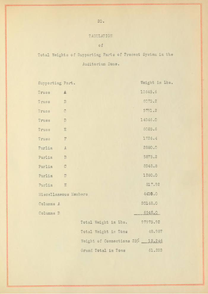
20
TABULATION
of
Total Weights o f Supporting Parts o f Present System in the
Auditorium Dome.
Supporting Part. Weight in Lbs.
Truss A 13645.6
T russ E 6075.2
Truss r* 5791.2
Truss D 14346.0
Truss E 6085.6
Truss TJ!r 1726.4
Purlin A 2880.0
Purlin E 5875.2
Purlin C 8348.8
Purlin D 1280.0
Purlin E 317.92
M iscellaneous Members 4410.0
Columns A 20148.0
Columns B 6546.0
Total Weight in Lbs. 97975.92
Total Weight in Tons 48,987
Weight o f Connections 25^ 12.246
Grand Total in Tons 61.223
21.
Y U j. . . Conclusion:
As stated at the outset the primary purpose o f th is
th e s is was tc redesign the stee l which supports the dome o f the
Auditorium, but i t was tbrs purpose also to compare the proposed
system with the o ld . Tith the idea o f comparison as w ell as re
design in mind i t was thought best to present drawings in plan
and section o f the two systems in order to give a defin ate idea
o f th e ir p o s it ion in the dome where a glance w ill show the great
er s im p lic ity o f the proposed system.
In arriv ing at the weight o f s tee l used in the pres
ent system, schedules o f the s izes and weights o f the members
were made and are shown on pages eleven to twenty in c lu s iv e .
The to ta l amount o f s tee l used in the present system is 61.23
tons while the proposed system w il l require 55.51 tons only,
a saving in favor o f the proposed system o f 5*72 tons or 9.35
per cent. The actual cost o f s tee l at the time the bu ild ing was
erected could not be obtained,though in the m ajority o f sim ilar
work done at that time i t was a t r i f l e over eighty d o lla rs a ton.
Assuming a p rice o f eighty d o lla rs per ton for the s te e l in place
there is an actual saving o f $457.50 in favor o f the proposed
system.
In addition to having the advantage o f lower co s t ,
the proposed system is much more simple th erfore i t would be more
rea d ily fabricated and erected . Being composed o f eighteen dupli
cate h a lf trusses as against th ir ty s ix trusses o f s ix d iffe ren t

22,
types in the o ld system i t i s obvious that i t has the advantage
o f s im p lic ity .
R ealizing that the o r ig in a l system was designed by a
reputable engineer and that the design may have been in fluenced
by conditions o f which we are not cognizant,we wish to state
that i t was not our in ten tion in the work here presented to
take a c r i t i c a l attitude unfavorable to the present system but
to present fa cts that in d ica te that the proposed system has some
advantages over the old .

-Sheat No 2.-


W in d-L oa d Norm al d oP u rlin s.
4 3 3 4
Wind L oa d Norix<$caU I‘‘= lo*
T r u s s D 'la g ra r Scale-£‘*lfd.
Diagv-ai
D R A W IN G S MO U2A a THESIS
b y
GEO-E-MelNTYRE and 14LTOSTER..
-bheei No j*
o laF-u*3+re.g>£) Didgram
•s~wr.su-.. 5TR,L<5C «5HELT ofthe PROPOdLDOYCTE.il °f SUPPORT
-f o r +He
AUDITORIUM DOME
"Wind L oa d o f 3 o lb jserscjT bod on a V e r t lealP la n e R e d u c e d d o l l s C om b on etvt N orm al
do \ We "R oo f-
h-14 in oy sd e m ©f T russ*•Scq l e i =12


![[Please list the analysis conducted] - Baja SAE Baja SAE Redesign Comparison... · Web view2016 Baja SAE Design Comparison Document 2016 Baja SAE Design Comparison Document 2016 Baja](https://cdn.vdocuments.site/doc/165x107/5ab1e61b7f8b9a284c8d112e/please-list-the-analysis-conducted-baja-baja-sae-redesign-comparisonweb-view2016.jpg)
