Page 1
DPR 250
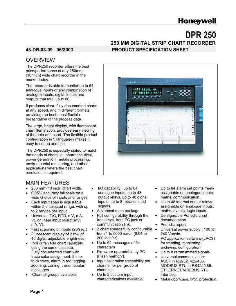
250 MM DIGITAL STRIP CHART RECORDER43-DR-03-09 06/2003 PRODUCT SPECIFICATION SHEET OVERVIEW The DPR250 recorder offers the best price/performance of any 250mm (10�inch) wide chart recorder in the market today. The recorder is able to monitor up to 64 analogue inputs or any combination of analogue inputs, digital inputs and outputs that total up to 80.
It produces clear, fully documented charts at any speed, and in different formats, providing the best, most flexible presentation of the process data.
The large, bright display, with fluorescent chart illumination, provides easy viewing of the data and chart. The flexible product configuration in 5 languages makes it easy to set up and use.
The DPR250 is especially suited to match the needs of chemical, pharmaceutical, power generation, metals processing, environmental monitoring, and other applications where the best chart resolution is required.
MAIN FEATURES • 250 mm (10 inch) chart width. • 0.05% accuracy full scale on a
wide choice of inputs and ranges. • Each input span is adjustable
within the selected range, with up to 2 ranges per input.
• Universal (T/C, RTD, mV, mA, V), or linear input board (mV, mA, V).
• Fast scanning of inputs (20/sec.) • Fluorescent display of 2 row of
16 digits, adjustable brightness. • Roll or fan fold chart capability
using the same cassette. Fully documented chart with trace color assignment, thin or thick trace, alarm in red tagging, zooming, zoning, trend, tabular, messages.
• Channel groups available.
• I/O capability : up to 64 analogue inputs, up to 48 output relays, up to 48 digital inputs, up to 8 retransmitted signals.
• Advanced math package • Full configurability through the
front keys, front PC jack or communication link.
• 2 chart speeds fully configurable from 1 to 5000 mm/h (0.04 to 200 inch/hr).
• Up to 64 messages of 64 characters
• Firmware upgradable by PC (Flash memory).
• Input calibration traceability per channel, or per group of channels.
• Up to 2 custom-input characterizations available.
• Up to 64 alarm set points freely assignable on analogue inputs, maths, communication.
• Up to 48 internal output relays assignable on analogue inputs, maths, events, logic inputs.
• Configurable Periodic chart documentation.
• Periodic report. • Universal power supply : 100 to
240 Vac/dc. • PC application software (LPCS)
for trending, monitoring, archiving, configuration.
• Up to 8 retransmitted signals. • Universal communication:
ASCII in RS232, 422/485. MODBUS RTU in RS422/485. ETHERNET/MODBUS RTU Interface.
• Metal door/case, IP55 protection.
Page 2
Clear and fully documented chart DPR250 Trend printing mode
_ 20.30 15 SEP 97 100 mm / h # 05
_ 20.35 AL01 (AN01) SP 100.0 ^ ON ADJUST OIL TEMPERATURE
0.000 400.0 800.0 1200 1600 2000(03) Furnace DEG C
21.00 15 SEP 97
CH11 30.23 RpmCH06 150.8 m3 / hCH01 70.20 °C
CH12 15.24 BARCH07 2.350 °CCH02 45.89 mV
CH13 50.36 L/mnCH08 560.8 RpmCH 03 12.66 Ohm
CH14 200.1 DEG CCH09 127.3 WhCH 04 258.1 Psi
CH15 800.5 Kg / hCH10 0.3680 ACH05 2358 °K
DI 01= OFF DI 02 = ON
21.15 DI02 = ON
0 (08) MOTOR K Rpm 2000
-100 0 100 (04) Pressure Psi 200 300 400
WATCH OIL PRESSURE_ 21.46 AL02 (04) SP 230.0 ^ ON
_ 22.00 15 SEP 97 GROUP A 100 mm / h # 05
_ 20.55 AL01 ( AN01) SP 100.0 ^ OFF
1 Heater
8 Motor B
2 Transmit
14
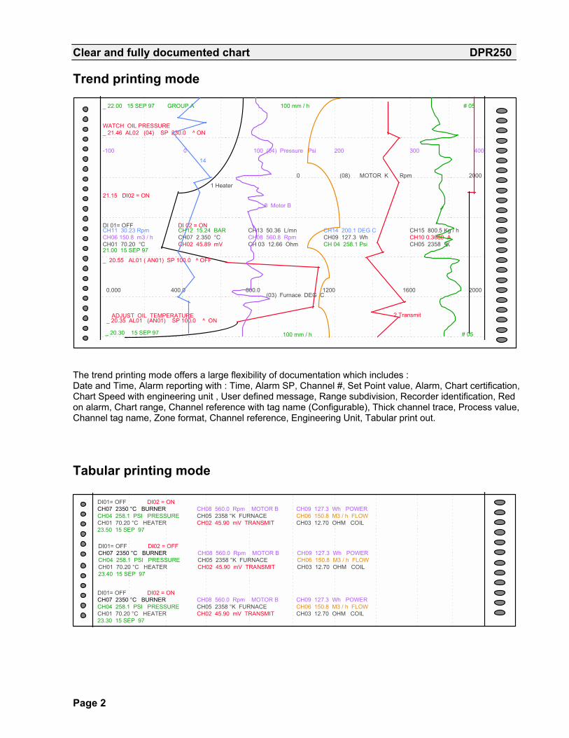
The trend printing mode offers a large flexibility of documentation which includes : Date and Time, Alarm reporting with : Time, Alarm SP, Channel #, Set Point value, Alarm, Chart certification, Chart Speed with engineering unit , User defined message, Range subdivision, Recorder identification, Red on alarm, Chart range, Channel reference with tag name (Configurable), Thick channel trace, Process value, Channel tag name, Zone format, Channel reference, Engineering Unit, Tabular print out. Tabular printing mode
DI01= OFF DI02 = ON CH07 2350 °C BURNER CH08 560.0 Rpm MOTOR B CH09 127.3 Wh POWERCH04 258.1 PSI PRESSURE CH05 2358 °K FURNACE CH06 150.8 M3 / h FLOWCH01 70.20 °C HEATER CH02 45.90 mV TRANSMIT CH03 12.70 OHM COIL23.50 15 SEP 97
DI01= OFF DI02 = OFFCH07 2350 °C BURNER CH08 560.0 Rpm MOTOR B CH09 127.3 Wh POWERCH04 258.1 PSI PRESSURE CH05 2358 °K FURNACE CH06 150.8 M3 / h FLOWCH01 70.20 °C HEATER CH02 45.90 mV TRANSMIT CH03 12.70 OHM COIL23.40 15 SEP 97
DI01= OFF DI02 = ON CH07 2350 °C BURNER CH08 560.0 Rpm MOTOR B CH09 127.3 Wh POWERCH04 258.1 PSI PRESSURE CH05 2358 °K FURNACE CH06 150.8 M3 / h FLOWCH01 70.20 °C HEATER CH02 45.90 mV TRANSMIT CH03 12.70 OHM COIL23.30 15 SEP 97

Page 3
Rugged, Simple and modular Construction DPR250
Cassette for roll or fan fold chart
Alarm/digital boards
Power supply
Mother Board
Ink Cartridge
Case
Chassis
Input boards
Terminals
Door
MMI Configuration keys
• Easy to install ... easy to use ... easy to maintain : The DPR250 with its modular design and rugged construction, simplifies maintenance. Many parts are common with the DPR180 thus reducing spare parts inventory. It's operator - friendly configuration keys, the sophisticated display, easy product configuration and customized charts insure accurate monitoring and recording of the process. • Easy access : the access to the chart, and the ink cartridge is very easy. The simple, modular construction of plug-in modules, along with the low cost and extra long life of consumables, further reduces the maintenance cost. • Universal power supply module : the universal switching mode power supply simplifies installation of the recorder by accepting voltages from 100 to 240 Vac/dc, 50/60 Hz. • Local configuration : A user friendly program with local language prompts (English, French, German, Italian or Spanish) permits a full configuration of the recorder using the front keys. A multilevel password protects against unauthorized changes of product configuration. • Digital Display : The Vacuum fluorescent dot matrix display, is 2 lines of 16 digits, 8.5 mm high (0.33�). This allows for flexible displaying and provides clear operator information. Display illumination is configurable to allow for improved viewing based on customer requirements. • Chart illumination : The chart illumination makes traces and current printed values immediately visible, even from a distance and in any ambient light condition. • Two paper types : Either chart roll or fan fold paper can be installed into the common chart cassette. The large capacity cassette holds 35 meters (115ft) of chart paper, reducing the maintenance time required between chart changes. Uses the same charts and ink cartridge as the DPR3000, thus providing for common consumables.
PC Configuration
Jack
• PC configuration : By using the front communication jack, the recorder can be configured from a personal computer, using an optional PC interface module. In addition to configuration, the PC interface provides the ability to upload, download, modify, store the recorder configuration and initiates service diagnostics as well as being able to upgrade the recorders product firmware. The PC Configuration software allows the creation of a custom characterization of up to 50 points for special ranges.

Page 4
DPR 250 FUNCTIONAL SPECIFICATIONS Technical data DPR250 Technology Microprocessor-based (32 bits), with non volatile memory.
Flash memory for product software upgrade, or specials, via the front jack. Analogue inputs
Number of inputs From 4 up to 64 in groups of 4. Note. Above 32 inputs could limit the total number of alarm outputs or digital inputs.
Input boards 2 types : 4 linear inputs per board : mV, V, mA 4 universal inputs per board : mV, V, mA, T/C, RTD, Ohms
Signal source Thermocouple with cold junction compensation, or with remote compensation temperature configurable between 0 to 80ºC (32 to 176ºF) Line resistance up to 1000 Ohms for T/C, mV, mA, V RTD Pt100 Ohms, 3 wire connections, 40 Ohms balanced max.
Basic math functions
Square root extraction or channel differential are standard.
Filter Digital filter configurable per input from 0 to 99 sec. Field calibration Channel calibration 0 to 100% span (or calibration of a group of identical channels)
can be made to certify sensor loop. Burnout T/C, mV, V (except following ranges) configurable to upscale, downscale or none
Volt : -500, 0, 500 mV ; -1, 0, 1V ; -2, 0, 2V; -5, 0, 5V ; 0, 10V ; -10, 0, 10V : Inherent to Zero volt. RTD : inherent upscale ; mA : inherent downscale.
Scanning time 2 channels = 105 msec, 4 ch = 210 msec, 8 ch = 420 msec, 12 ch = 630 msec, 16 ch = 840 msec, 20 ch = 1 sec, 24 ch = 1.2 sec, 32 ch = 1.6 sec, 64 ch = 3.3 sec.
Input impedance 10 MOhms for T/C and mV inputs; > 1 MOhm for V input Stray rejection Series mode > 60 dB. Common mode at 120 Vac > 130 dB Display Fluorescent
display 2 rows of 16 digits, 8.5 mm (.33 inch) high, matrix display. Can display 1 or 2 PV values (5 digits) per line, engineering units (5 digits), alarm status, tag name, math, speed, event messages etc.
Brightness The display brightness is configurable Record Chart 250 mm (10�) width Traces Up to 32 traces, configurable in 6 colors, thin or thick traces, plus digital traces Trace assignment Traces are configurable on analogue inputs, math, communication or digital inputs Scaling Per input, up to 2 analogue scales can be configured to be printed on the chart,
with engineering units, channel reference and tag name. Each input can be configured independently. The scale can be linear, with up to 10 sub-divisions
Print mode Trend : Up to 32 traces, with periodic chart documentation configurable in time, from 1 minute to 24 hours with date, time, scales, digital PV print-out over traces or on blank paper, with channel reference, digital traces, alarm messages and customer message. Tabular : Tabular print-out configurable in time from 1 to 1440 minutes with channel number, tag name, digital PV value, engineering unit, alarm status.
Zoning Each input can be scaled between 0 to 100% of the chart (minimum zone = 20%). Printing group Up to 2 groups of channels can be defined, with printing selection by :
Alarm, logic inputs or logic triggers Pen carriage speed 1.95 second full scale Chart length Roll or fan fold chart 35 meters (115 ft) Chart speed 1 or 2 chart speed, fully configurable, selected by : Logic input, alarm
communication, front key. Speed setting Speeds 1 and 2 are configurable from 1 (0.04�) up to 5000 mm/hr (200�)
Resolution Chart resolution is 0.19 mm (0.0075�)
Page 5
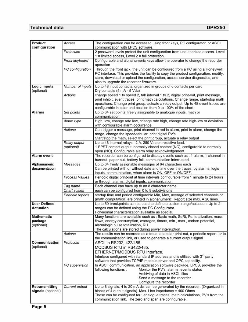
Technical data DPR250 Product configuration
Access The configuration can be accessed using front keys, PC configurator, or ASCII communication with LPCS software.
Protection 2 password levels protect the unit configuration from unauthorized access. Level 1 = limited access, Level 2 = full protection.
Front keyboard Configurable and alphanumeric keys allow the operator to change the recorder operation
PC configuration Through the front jack, the unit can be configured from a PC using a Honeywell PC interface. This provides the facility to copy the product configuration, modify, store, download or upload the configuration, access service diagnostics, and also to upgrade the recorder firmware.
Logic inputs (optional)
Number of inputs Up to 48 input contacts, organized in groups of 6 contacts per card Dry contacts (5 mA - 5 Vdc)
Actions change speed 1 to speed 2, tab interval 1 to 2, digital print-out, print message, print inhibit, event traces, print math calculations. Change range, start/stop math operations. Change print group, actuate a relay output. Up to 48 event traces are configurable in color and position from 0 to 100% of the chart
Alarms Set points Up to 64 set points, freely assignable to analogue inputs, math or communication.
Alarm type High, low, change rate low, change rate high, change rate high-low or deviation with configurable alarm occurrence.
Actions Can trigger a message, print channel in red in alarm, print in alarm, change the range, change the speed/tabular, print digital PV's Start/stop the math, select the print group, actuate a relay output
Relay output (optional)
Up to 48 internal relays : 2 A, 250 Vac on resistive load. 1 SPST contact output, normally closed contact (NC), configurable to normally open (NO). Configurable alarm relay acknowledgement.
Alarm event The recorder can be configured to display events such as : 1 alarm, 1 channel in burnout, paper out, battery fail, communication interrupted.
Alphanumeric documentation
Messages Up to 64 freely assignable messages of 64 characters each Can be printed with or without date and time over the traces, by alarms, logic inputs, communication, when alarm is ON, OFF or ON/OFF.
Process Values Periodic digital print-out at time intervals configurable from 1 minute to 24 hours or through alarms, digital inputs, communication.
Tag name Each channel can have up to an 8 character name Chart scales each can be configured from 0 to 9 subdivisions Periodic reports startup time and period configurable Min, Max, average of selected channels or
(math computation) are printed in alphanumeric. Report size max. = 20 lines. User-Defined Actuation
Up to 50 breakpoints can be used to define a custom range/actuation. Up to 2 ranges can be defined using the PC Configurator. Polynomial characterization available as special.
Mathematic package (optional)
Many functions are available such as : Basic math, SqRt, Fo, totalization, mass flows, energy consumption, averages, timers, min., max., carbon potential, alarm/logic pulse totalization, RH. The calculations are stored during power interruption.
Actions The results can be recorded as a trace, a tabular print-out, a periodic report, or to the communication link, or used to generate a current output signal
Communication (optional)
Protocols ASCII in RS232, 422/485. MODBUS RTU in RS422/485. ETHERNET/MODBUS RTU Interface, Interface configured with standard IP address and is utilized with 3rd party software that provides TCP/IP modbus driver and OPC capability.
PC supervision In ASCII communication, an application software package, LPCS, provides the following functions : Monitor the PV's, alarms, events status Archiving of data in ASCII files Send a message to the recorder Configure the recorder
Retransmitting signals (optional)
Current output Up to 8 signals, 4 to 20 mA dc, can be generated by the recorder. (Organized in blocks of 4 output signals). Max. Line impedance = 400 Ohms These can be configured for : analogue traces, math calculations, PV's from the communication link. The zero and span are configurable.
Page 6
Technical data DPR250
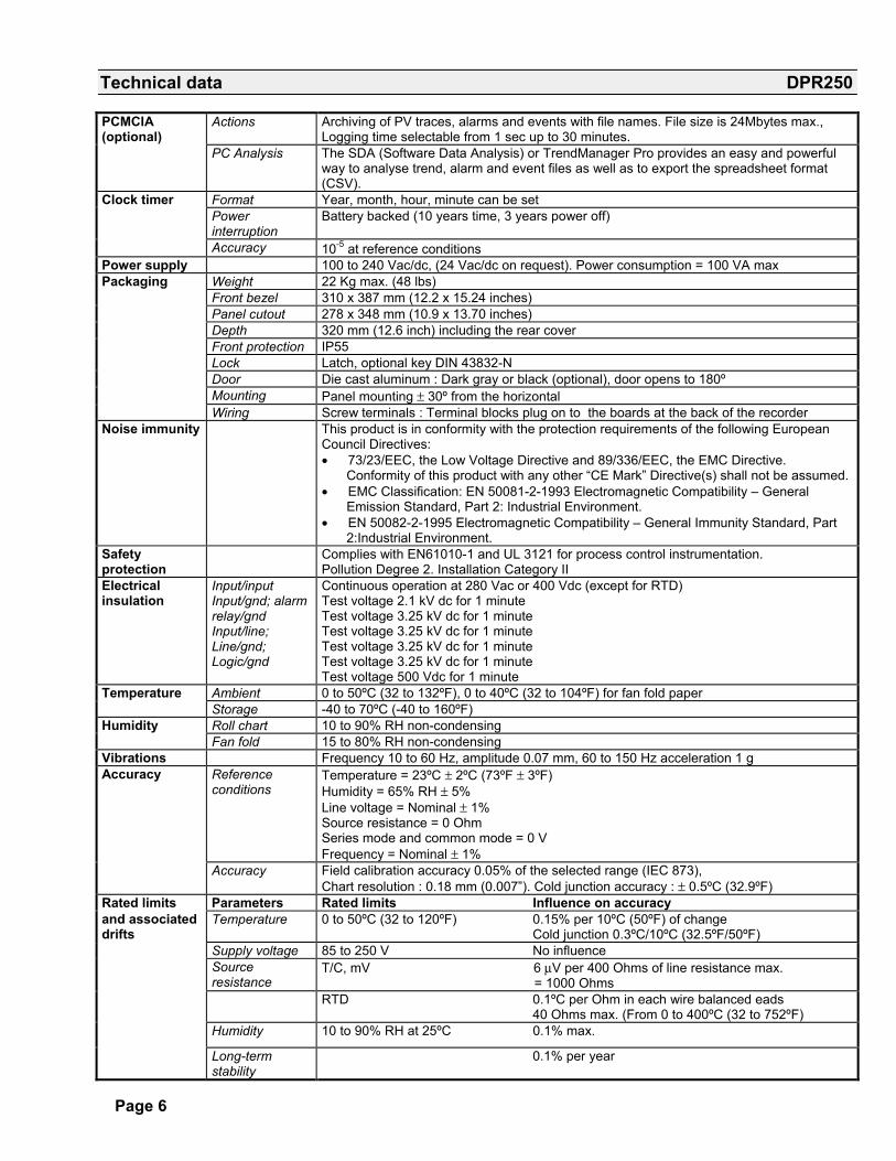
PCMCIA (optional)
Actions Archiving of PV traces, alarms and events with file names. File size is 24Mbytes max., Logging time selectable from 1 sec up to 30 minutes.
PC Analysis The SDA (Software Data Analysis) or TrendManager Pro provides an easy and powerful way to analyse trend, alarm and event files as well as to export the spreadsheet format (CSV).
Clock timer Format Year, month, hour, minute can be set Power
interruption Battery backed (10 years time, 3 years power off)
Accuracy 10-5 at reference conditions Power supply 100 to 240 Vac/dc, (24 Vac/dc on request). Power consumption = 100 VA max Packaging Weight 22 Kg max. (48 lbs) Front bezel 310 x 387 mm (12.2 x 15.24 inches) Panel cutout 278 x 348 mm (10.9 x 13.70 inches) Depth 320 mm (12.6 inch) including the rear cover Front protection IP55 Lock Latch, optional key DIN 43832-N Door Die cast aluminum : Dark gray or black (optional), door opens to 180º Mounting Panel mounting ± 30º from the horizontal Wiring Screw terminals : Terminal blocks plug on to the boards at the back of the recorder Noise immunity This product is in conformity with the protection requirements of the following European
Council Directives: • 73/23/EEC, the Low Voltage Directive and 89/336/EEC, the EMC Directive.
Conformity of this product with any other �CE Mark� Directive(s) shall not be assumed. • EMC Classification: EN 50081-2-1993 Electromagnetic Compatibility � General
Emission Standard, Part 2: Industrial Environment. • EN 50082-2-1995 Electromagnetic Compatibility � General Immunity Standard, Part
2:Industrial Environment. Safety protection
Complies with EN61010-1 and UL 3121 for process control instrumentation. Pollution Degree 2. Installation Category II
Electrical insulation
Input/input Input/gnd; alarm relay/gnd Input/line; Line/gnd; Logic/gnd
Continuous operation at 280 Vac or 400 Vdc (except for RTD) Test voltage 2.1 kV dc for 1 minute Test voltage 3.25 kV dc for 1 minute Test voltage 3.25 kV dc for 1 minute Test voltage 3.25 kV dc for 1 minute Test voltage 3.25 kV dc for 1 minute Test voltage 500 Vdc for 1 minute
Temperature Ambient 0 to 50ºC (32 to 132ºF), 0 to 40ºC (32 to 104ºF) for fan fold paper Storage -40 to 70ºC (-40 to 160ºF) Humidity Roll chart 10 to 90% RH non-condensing Fan fold 15 to 80% RH non-condensing Vibrations Frequency 10 to 60 Hz, amplitude 0.07 mm, 60 to 150 Hz acceleration 1 g Accuracy Reference
conditions Temperature = 23ºC ± 2ºC (73ºF ± 3ºF) Humidity = 65% RH ± 5% Line voltage = Nominal ± 1% Source resistance = 0 Ohm Series mode and common mode = 0 V Frequency = Nominal ± 1%
Accuracy Field calibration accuracy 0.05% of the selected range (IEC 873), Chart resolution : 0.18 mm (0.007�). Cold junction accuracy : ± 0.5ºC (32.9ºF)
Rated limits Parameters Rated limits Influence on accuracy and associated drifts
Temperature 0 to 50ºC (32 to 120ºF) 0.15% per 10ºC (50ºF) of change Cold junction 0.3ºC/10ºC (32.5ºF/50ºF)
Supply voltage 85 to 250 V No influence Source
resistance T/C, mV 6 µV per 400 Ohms of line resistance max. = 1000 Ohms
RTD 0.1ºC per Ohm in each wire balanced eads 40 Ohms max. (From 0 to 400ºC (32 to 752ºF)
Humidity 10 to 90% RH at 25ºC 0.1% max.
Long-term stability
0.1% per year
Page 7
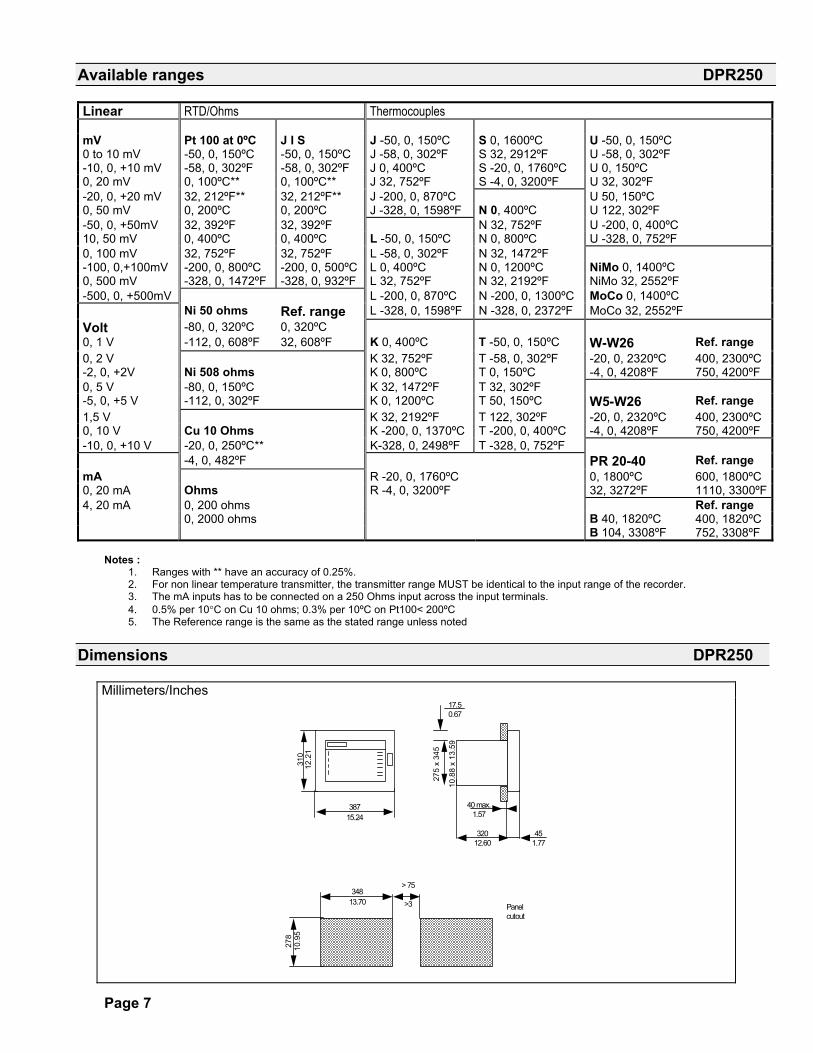
Available ranges DPR250
Linear RTD/Ohms Thermocouples mV Pt 100 at 0ºC J I S J -50, 0, 150ºC S 0, 1600ºC U -50, 0, 150ºC 0 to 10 mV -50, 0, 150ºC -50, 0, 150ºC J -58, 0, 302ºF S 32, 2912ºF U -58, 0, 302ºF -10, 0, +10 mV -58, 0, 302ºF -58, 0, 302ºF J 0, 400ºC S -20, 0, 1760ºC U 0, 150ºC 0, 20 mV 0, 100ºC** 0, 100ºC** J 32, 752ºF S -4, 0, 3200ºF U 32, 302ºF -20, 0, +20 mV 32, 212ºF** 32, 212ºF** J -200, 0, 870ºC U 50, 150ºC 0, 50 mV 0, 200ºC 0, 200ºC J -328, 0, 1598ºF N 0, 400ºC U 122, 302ºF -50, 0, +50mV 32, 392ºF 32, 392ºF N 32, 752ºF U -200, 0, 400ºC 10, 50 mV 0, 400ºC 0, 400ºC L -50, 0, 150ºC N 0, 800ºC U -328, 0, 752ºF 0, 100 mV 32, 752ºF 32, 752ºF L -58, 0, 302ºF N 32, 1472ºF -100, 0,+100mV -200, 0, 800ºC -200, 0, 500ºC L 0, 400ºC N 0, 1200ºC NiMo 0, 1400ºC 0, 500 mV -328, 0, 1472ºF -328, 0, 932ºF L 32, 752ºF N 32, 2192ºF NiMo 32, 2552ºF -500, 0, +500mV L -200, 0, 870ºC N -200, 0, 1300ºC MoCo 0, 1400ºC Ni 50 ohms Ref. range L -328, 0, 1598ºF N -328, 0, 2372ºF MoCo 32, 2552ºF Volt -80, 0, 320ºC 0, 320ºC 0, 1 V -112, 0, 608ºF 32, 608ºF K 0, 400ºC T -50, 0, 150ºC W-W26 Ref. range 0, 2 V K 32, 752ºF T -58, 0, 302ºF -20, 0, 2320ºC 400, 2300ºC -2, 0, +2V Ni 508 ohms K 0, 800ºC T 0, 150ºC -4, 0, 4208ºF 750, 4200ºF 0, 5 V -80, 0, 150ºC K 32, 1472ºF T 32, 302ºF -5, 0, +5 V -112, 0, 302ºF K 0, 1200ºC T 50, 150ºC W5-W26 Ref. range 1,5 V K 32, 2192ºF T 122, 302ºF -20, 0, 2320ºC 400, 2300ºC 0, 10 V Cu 10 Ohms K -200, 0, 1370ºC T -200, 0, 400ºC -4, 0, 4208ºF 750, 4200ºF -10, 0, +10 V -20, 0, 250ºC** K-328, 0, 2498ºF T -328, 0, 752ºF -4, 0, 482ºF PR 20-40 Ref. range mA R -20, 0, 1760ºC 0, 1800ºC 600, 1800ºC 0, 20 mA Ohms R -4, 0, 3200ºF 32, 3272ºF 1110, 3300ºF4, 20 mA 0, 200 ohms Ref. range 0, 2000 ohms B 40, 1820ºC 400, 1820ºC B 104, 3308ºF 752, 3308ºF
Notes :
1. Ranges with ** have an accuracy of 0.25%. 2. For non linear temperature transmitter, the transmitter range MUST be identical to the input range of the recorder. 3. The mA inputs has to be connected on a 250 Ohms input across the input terminals. 4. 0.5% per 10°C on Cu 10 ohms; 0.3% per 10ºC on Pt100< 200ºC 5. The Reference range is the same as the stated range unless noted
Dimensions DPR250
Millimeters/Inches
278
10.9
5
34813.70
> 75
>3 Panel cutout
32012.60
451.77
40 max.1.57
275
x 34
5
10.8
8 x
13.5
9
38715.24
310
12.2
1
17.50.67
Page 8
Sales and Service For application assistance, current specifications, pricing, or name of the nearest Authorized Distributor, contact one of the offices below. Warranty/Remedy Honeywell warrants goods of its manufacture as being free of defective materials and faulty work-manship. Contact your local sales office of warranty information. If warranted goods are returned to Honeywell during the period of coverage, Honeywell will repair of replace without charge those items it finds defective. The foregoing is Buyer�s sole remedy and is in lieu of all other warranties, expressed or implied, including those of merchantability and fitness for a particular purpose. Specifications may change without notice. The information we supply is believed to be accurate and reliable as of printing. However, we assume no responsibility for its use. While we provide application assistance personally, through our literature and the Honeywell website, it is up to the customer to determine the suitability of the product in the application. ASIA PACIFIC
Control Products Asia Pacific Headquarters Phone: +(65) 6355-2828 Fax: +(65) 6445-3033
Australia Honeywell Limited Phone: +(61) 2-9370-4500 FAX: +(61) 2-9370-4525 Toll Free 1300-36-39-36 Toll Free Fax: 1300-36-04-70
China – PRC - Beijing Honeywell China Inc. Phone: +(86-10) 8458-3280 Fax: +(86-10) 8458-3102
China – PRC - Shanghai Honeywell China Inc. Phone: (86-21) 6237-0237 Fax: (86-21) 6237-1237 China - Hong Kong S.A.R. Honeywell Ltd. Phone: +(852) 2953-6412 Fax: +(852) 2953-6767 China – PRC - Chengdu Honeywell China Inc. Phone: +(86-28) 6786-348 Fax: +(86-28) 6787-061 China – PRC - Guangzhou Honeywell China Inc. Phone: +(86-20) 3879-1169 Fax: +(86-20) 3879-1269 China – PRC - Shenzhen Honeywell China Inc. Phone: +(86) 755-518-1226 Fax: +(86) 755-518-1221 Indonesia Honeywell Indonesia Pte Ltd. Phone: +(62) 21-535-8833 FAX: +(62) 21-5367 1008 India TATA Honeywell Ltd. Phone: +(91) 20 687 0445/0446 Fax: +(91) 20 681 2243/ 687 5992 Japan Honeywell Inc Phone: +(81) 3 5440 1425 Fax: +(81) 3 5440 1368 South Korea Honeywell Korea Co Ltd Phone: +(822) 799-6167 Fax: +(822) 792-9013
Malaysia Honeywell Engineering Sdn Bhd Phone: +(60-3) 7958-4988 Fax: +(60-3) 7958-8922 New Zealand Honeywell Limited Phone: +(64-9) 623-5050 Fax: +(64-9) 623-5060 Toll Free (0800) 202-088 Philippines Honeywell Systems (Philippines) Inc. Phone: +(63-2) 636-1661 /1662 Fax: +(63-2) 638-4013 Singapore Honeywell South East Asia Phone: +(65) 6355-2828 Fax: +(65) 6445-3033 Thailand Honeywell Systems (Thailand) Ltd. Phone: +(662) 693-3099 FAX: +(662) 693-3085 Taiwan R.O.C. Honeywell Taiwan Ltd. Phone: +(886-2) 2245-1000 FAX: +(886-2) 2245-3242
EUROPE
Austria Honeywell Austria GmbH Phone: +43 (316)400123 FAX: +43 (316)40017 Belgium Honeywell SA/NV Phone: +31(0)205656999 FAX: +31(0)165330746 Bulgaria Honeywell EOOD Phone: +(359) 2 79 40 27 FAX: +(359) 2 79 40 90 Czech Republic Honeywell spol. s.r.o. Phone: +420-54324-5014 FAX: +420-54324-5011
Denmark Honeywell A/S Phone: +(45) 39 55 55 55 FAX: +(45) 39 55 55 58 Finland Honeywell OY Phone: +358 (3) 2727625 FAX: +358 (3) 2728600 France Honeywell SA Phone: +33 (0)1 60198075 FAX: +33 (0)1 60198201 Germany Honeywell AG Phone: +49 (69)8064336 FAX: +49 (69)806497336 Hungary Honeywell Kft. Phone: +36-1-451 4335 FAX: +36-1-451 4343 Italy Honeywell S.p.A. Phone: +39 02 9214 6503 FAX: +39 0292146377 The Netherlands Honeywell B.V. Phone: +31(0)205656999 FAX: +31(0)165330746 Norway Honeywell A/S Phone: (45) 39 55 55 55 Poland Honeywell Sp. zo.o Phone: +48-22-6060900 FAX: +48-22-6060901 Portugal Honeywell Portugal Lda Phone: +351 21 424 5000 FAX: +351 21 424 50 99 Romania Honeywell Bucharest Phone: 40212110076 FAX: +40 (40212103375) Commonwealth of Independent States (CIS) Z.A.O. Honeywell Phone: +(7 095) 796 98 36 FAX: +(7 095) 796 98 93 Slovak Republic Honeywell s.r.o. Phone: +421-2-58247 410 FAX: +421-2-58247 415
Spain Honeywell S.A. Phone: +34 (0)91313 61 00 FAX: +34 (0)91313 61 30
Sweden Honeywell AB Phone: +(46) 8 775 55 00 FAX: +(46) 8 775 56 00
Switzerland Honeywell AG Phone: +41 18552448 FAX: +(41) 1 855 24 45
Turkey Honeywell Turkey A.S. Phone: +90 216 575 6600 FAX: +90 216 575 6637
United Kingdom Honeywell Control Systems Ltd Phone: +(44) 1698 481730 FAX: +(44) 1698 481276 MIDDLE EAST
Abu Dhabi U A E Middle East Headquarters Honeywell Middle East Ltd Phone: +971 2 4041220 FAX: +971 2 4432536
Sultanate of Oman Honeywell & Co Oman LLC Phone: +968 701397 FAX +968 787351
Egypt Honeywell Egypt Ltd Phone: +202 4514460 /1/ 2/ 3/ 4/ 5/ 6 FAX : +2024514467
Saudia Arabia Honeywell Turki Arabia Limited Phone: +966-3-341-0140 Fax: +966-3-341-0216
Kuwait Honeywell Kuwait KSC Phone: +965 2421327 AFRICA
Mediterranean & African Distributors Honeywell SpA Phone: +39 (02) 250 10 604 FAX: +39 (02) 250 10 659
South Africa (Republic of) Honeywell Southern Africa Honeywell S.A. Pty. Ltd Phone: +27 11 6958000 FAX +27 118051504
NORTH AMERICA
Canada Honeywell LTD Phone: 1-800-737-3360 FAX: 1-800-565-4130
USA Honeywell Control Products, International Headquarters Phone: 1-800-537-6945 1-815-235-6847 FAX: 1-815-235-6545 E-mail: [email protected]
LATIN AMERICA
Argentina Honeywell S.A.I.C. Phone: +(54-11) 4383-3637 FAX: +(54-11) 4325-6470
Brazil Honeywell do Brasil & Cia Phone: +(55-11) 7266-1900 FAX: +(55-11) 7266-1905
Chile Honeywell Chile, S.A. Phone: +(56-2) 233-0688 FAX: +(56-2) 231-6679
Columbia Honeywell Columbia, S.A. Phone: +(57-1) 623-3239/3051 FAX: +(57-1) 623-3395
Ecuador Honeywell S.A. Phone: +(593-2) 981-560/1 FAX: +(593-2) 981-562
Mexico Honeywell S.A. de C.V. Phone: +(52) 55 5259-1966 FAX: +(52) 55 5570-2985
Peru Honeywell Peru Phone: +(511) 445-2136/1891 FAX: +(511) 348-3552
Puerto Rico Honeywell Inc. Phone: +(809) 792-7075 FAX: +(809) 792-0053
Trinidad Honeywell Inc Phone: +(868) 624-3964 FAX: +(868) 624-3969 Venezuela Honeywell CA Phone: +(58-2) 238-0211 FAX: +(58-2) 238-3391


![PORQUE HONEYWELL Patrick Bogaert]. 2 HONEYWELL - CONFIDENTIAL](https://cdn.vdocuments.site/doc/165x107/5665b4371a28abb57c900f84/porque-honeywell-patrick-bogaert-2-honeywell-confidential.jpg)
