Download - Radar Environment RF Generation - BGU

Radar Environment RF
Generation
Dr. Steffen Heuel
Technology Manager Aerospace & Defense
Rohde & Schwarz Munich, Germany

Typical navigation radar scenario
2
Tx
TxTx
Tx
Rx
Rx1+Rx2
Rx
Return from land clutter
North
N
S
W E
South
EastWest
Turning navigation
radar antenna
Visualization on a radar screen
Echoes are displayed in so called “range cells“
Coherent radars can also measure speed and
can therefore also display an echo in a
“Doppler cell“
The larger the radar return signal, the larger
the radar cross section i.e. the object, the
larger the dot on the screen

Conventional Test set-up for navigation radar testing
Tx
TxTx
Tx
Rx
Rx1+Rx2
Rx
Return from land clutter
Test ship with
radar under test
on board
Artificial targets
deployed on sea
ı Test Concept for Navigation Radars
Mount a real radar under test on a boat
Deploy artificial targets at the sea
ı Test Concept for airborne radars
Set up a flight campaign with artificial targets or use civil aircrafts
ı Test concept for ground radars
Set-up field-test in large area to test performance
3

Motivation and Approach
4
Target SimulationSea Clutter Simulation

Field-to-lab
ReduceCost, complexity & test
time
ImproveAccuracy, reliability &
repeatability

23.01.2017 6
Sea clutter generation

Radar Detection
Probability Density Function
23.01.2017 7
𝑃𝐹𝐴 False Alarm Probability
𝑃𝑀 Probability of Missing a Target
𝑃𝐷 Probability of Missing Detection
Rayleigh Distribution
Rice DistributionThreshold

Typical Sea Clutter
PPI view
23.01.2017 8
Range
Re
ce
ive
dP
ow
er
How to simulate
time and spatial
correlated sea
clutter?

ı Capillary waves
Wavelength of centimeters or less
Driven by local wind gusts
Stochastic model
ı Gravity waves
Wavelength of a few hundred meters down
to a meter
Created by stable winds over a large area
Physical model
Two scale model of the sea surface
23.01.2017 9
Courtesy of waterswaytravel.com
Courtesy of wikipedia.org
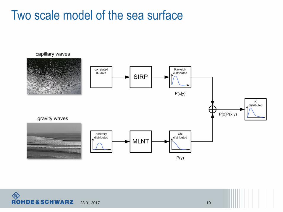
Two scale model of the sea surface
23.01.2017 10
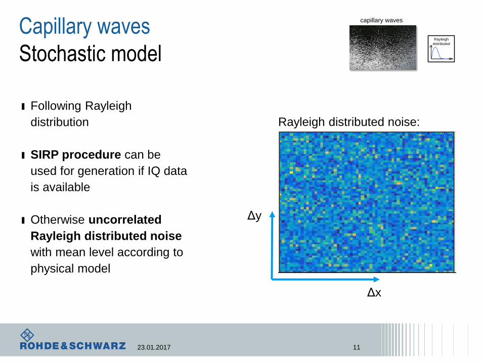
Capillary waves
Stochastic model
23.01.2017 11
ı Following Rayleigh
distribution
ı SIRP procedure can be
used for generation if IQ data
is available
ı Otherwise uncorrelated
Rayleigh distributed noise
with mean level according to
physical model
Rayleigh
distributed
capillary waves
Rayleigh distributed noise:
Δy
Δx

ı Use established model to simulate
sea surface
Parameters: average wave height and
period, spreading factor, sampling
frequency
ı Transform height of sea surface to
have a Chi-distribution
Transformation is performed with the
help of memoryless nonlinear
transformation (MLNT)
Shape parameter can be estimated
using available formulas
Gravity Waves
Physical Model
23.01.2017 12
Simulation of sea surface heights
arbitrary
distributed
gravity waves
Δy
Δx

23.01.2017 13
Data verification and signal
generation

IPIX datarecorded on Canadian East Coast in 1993
23.01.2017 14
KS-Test passed in 83% using
significance level α=0.05

Environment to multisegment waveform
|A|
R
|A|
R
|A|
R
...
Radar PPI
Map environment
to waveforms

ı Multisegment waveform (MSW) consists of multiple independent waveforms
ı Each radar “TX Pulse” triggers a segment (and the next segment…)
….
….
Segment
Marker
Segment
Marker
Segment
Marker
timeI/Q data
Environment simulation using multisegment
waveform (MSW)

Radar echo generation and environment simulation
R&S®SMW
Radar under
Test
RX
Antenna
Headmarker
TX Puls
Marker
+RF Out
TX
DigIQ,
LAN,
Ref
R&S®FSW
RF In
R&S®Radar Echo Generation
Sea Clutter
Additional RF
Signals, Echoes,
Jamming etc.

Measurement setup in the laboratory
Radar PPI
X-Band Radar TRX
Vector Signal
Generator
Dummy Load
Circulator
Signal and
Spectrum Analyser

Simulated Sea Clutter
Sea clutter
Moving target
Simulation
X-Band Radar
PPI Screenshot
Max range
set to 1.5NM
Radar suppresses sea
clutter in close range

Recorded Sea Clutter
ı Single radar echo
signal, moving target
with 100m/s in 5NM
range
ı Recorded sea clutter
Sea clutter
Moving target
Max range
set to 12NM
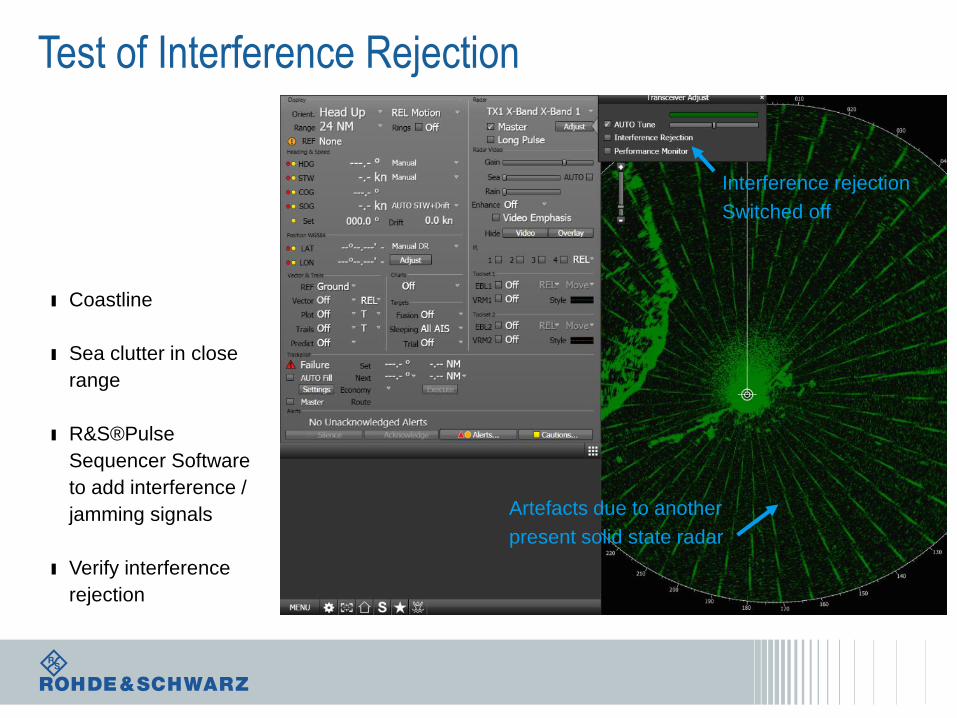
Test of Interference Rejection
ı Coastline
ı Sea clutter in close
range
ı R&S®Pulse
Sequencer Software
to add interference /
jamming signals
ı Verify interference
rejection
Interference rejection
Switched off
Artefacts due to another
present solid state radar
Thank you for
your attention!


