7/29/2019 Protecting Border Gateway Protocol for the Enterprise
http://slidepdf.com/reader/full/protecting-border-gateway-protocol-for-the-enterprise 1/19
Protecting Border Gateway Protocol for the Enterprise
ContentsSummary of Border Gateway Protocol
Summary of BGP Threats BGP Baseline Configurations
Baseline IP BGP Routing Tables BGP Threat Mitigations
BGP Neighbor Authentication with MD5
BGP Time To Live Security Check Configuring Maximum Prefixes
Filtering BGP Prefixes with Prefix Lists Filtering BGP Prefixes with Autonomous System Path Access Lists
AS Path Length Limiting
Infrastructure ACLs
Control Plane Policing
Conclusions
Acknowledgments
References
Summary of Border Gateway Protocol
The Border Gateway Protocol (BGP), which is defined in RFC 1163 and RFC 1267, is an Exterior Gateway Protocol (EGP) that
is most often associated with the Internet and with Service Provider (SP) networks. Because many networks utilize static routingand a single connection for Internet access, BGP is unnecessary. However, as organizations increase their web presence andreliance on the Internet for revenue, the need for reliable and geographically diverse Internet connectivity has become more
common. These needs are often met through multi-home configurations that require BGP for connectivity to an SP's BGP-
speaking routers. This emerging trend requires organizations to obtain a high level of BGP and BGP Security expertise that is
typically found in SPs. This document is intended to assist enterprise administrators who are using or investigating the use of
BGP as a routing protocol in their network.
Summary of BGP Threats
Administrators must understand many important aspects of BGP as a protocol to assess where it may be susceptible to various
forms of attack and where it must be protected. First, unlike other routing protocols that typically provide their own transport
layer (Layer 4) protocol, BGP relies on TCP as its transport protocol. BGP is susceptible to the same attacks that target any
TCP-based protocol, and it must be protected similarly. Additionally, because BGP as an application is vulnerable to various
threats, administrators must mitigate the risk and potential impact of associated exploit attempts. Some of these threats includethe following:
BGP Route Manipulation – This scenario occurs when a malicious device alters the contents of the BGP routing table,
which can, among other impacts, prevent traffic from reaching its intended destination without acknowledgement or
notification.
BGP Route Hijacking – This scenario occurs when a rogue BGP peer maliciously announces a victim's prefixes in an effortto reroute some or all traffic to itself for untoward purposes (for example, to view contents of traffic that the router would
otherwise not be able to read).
BGP Denial of Service (DoS) – This scenario occurs when a malicious host sends unexpected or undesirable BGP traffic to
a victim in an attempt to expend all available BGP or CPU resources, which results in a lack of resources for valid BGP
traffic processing.
Finally, inadvertent mistakes (or non-malicious actions) among BGP peers can also have a disruptive impact on a router's BGPprocess. Thus, security techniques should be applied to mitigate any impacts from these kinds of events as well.
This document will not cover all details of the BGP protocol itself, nor is it intended to detail the various forms of possible
attacks against BGP or BGP processes; however, the References section of this document does provide additional resources onthese topics. This paper will highlight several of the most important BGP security techniques that are used by SPs and show
their applicability in non-SP environments. No single security measure can adequately protect BGP. Like any security approach,applying several mechanisms to provide a "defense-in-depth" approach is the best method to help secure this protocol.
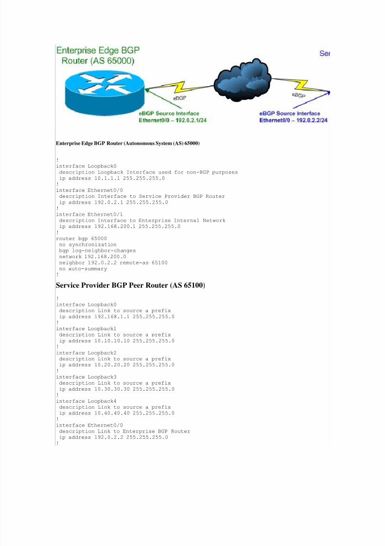
BGP Baseline ConfigurationsThe following Cisco IOS router configurations will be used as the baselines to demonstrate the various BGP security techniquesthat are described in this document:
Figure 1. BGP Peering Network Diagram
7/29/2019 Protecting Border Gateway Protocol for the Enterprise
http://slidepdf.com/reader/full/protecting-border-gateway-protocol-for-the-enterprise 2/19
Enterprise Edge BGP Router (Autonomous System (AS) 65000)
!
interface Loopback0
description Loopback Interface used for non-BGP purposes
ip address 10.1.1.1 255.255.255.0
!
interface Ethernet0/0description Interface to Service Provider BGP Router
ip address 192.0.2.1 255.255.255.0
!
interface Ethernet0/1
description Interface to Enterprise Internal Network
ip address 192.168.200.1 255.255.255.0
!
router bgp 65000
no synchronization
bgp log-neighbor-changes
network 192.168.200.0
neighbor 192.0.2.2 remote-as 65100
no auto-summary
!
Service Provider BGP Peer Router (AS 65100) !
interface Loopback0
description Link to source a prefix
ip address 192.168.1.1 255.255.255.0
!
interface Loopback1
description Link to source a prefix
ip address 10.10.10.10 255.255.255.0
!
interface Loopback2
description Link to source a prefix
ip address 10.20.20.20 255.255.255.0
!
interface Loopback3
description Link to source a prefixip address 10.30.30.30 255.255.255.0
!
interface Loopback4
description Link to source a prefix
ip address 10.40.40.40 255.255.255.0
!
interface Ethernet0/0
description Link to Enterprise BGP Router
ip address 192.0.2.2 255.255.255.0
!
7/29/2019 Protecting Border Gateway Protocol for the Enterprise
http://slidepdf.com/reader/full/protecting-border-gateway-protocol-for-the-enterprise 3/19
interface Ethernet0/1
description Link to source a prefix
ip address 192.168.210.1 255.255.255.0
!
router bgp 65100
no synchronization
bgp log-neighbor-changes
network 10.10.10.0 mask 255.255.255.0
network 10.20.20.0 mask 255.255.255.0network 10.30.30.0 mask 255.255.255.0
network 10.40.40.0 mask 255.255.255.0
network 192.168.1.0
network 192.168.210.0
neighbor 192.0.2.1 remote-as 65000
neighbor 192.0.2.1 default-originate
no auto-summary
!
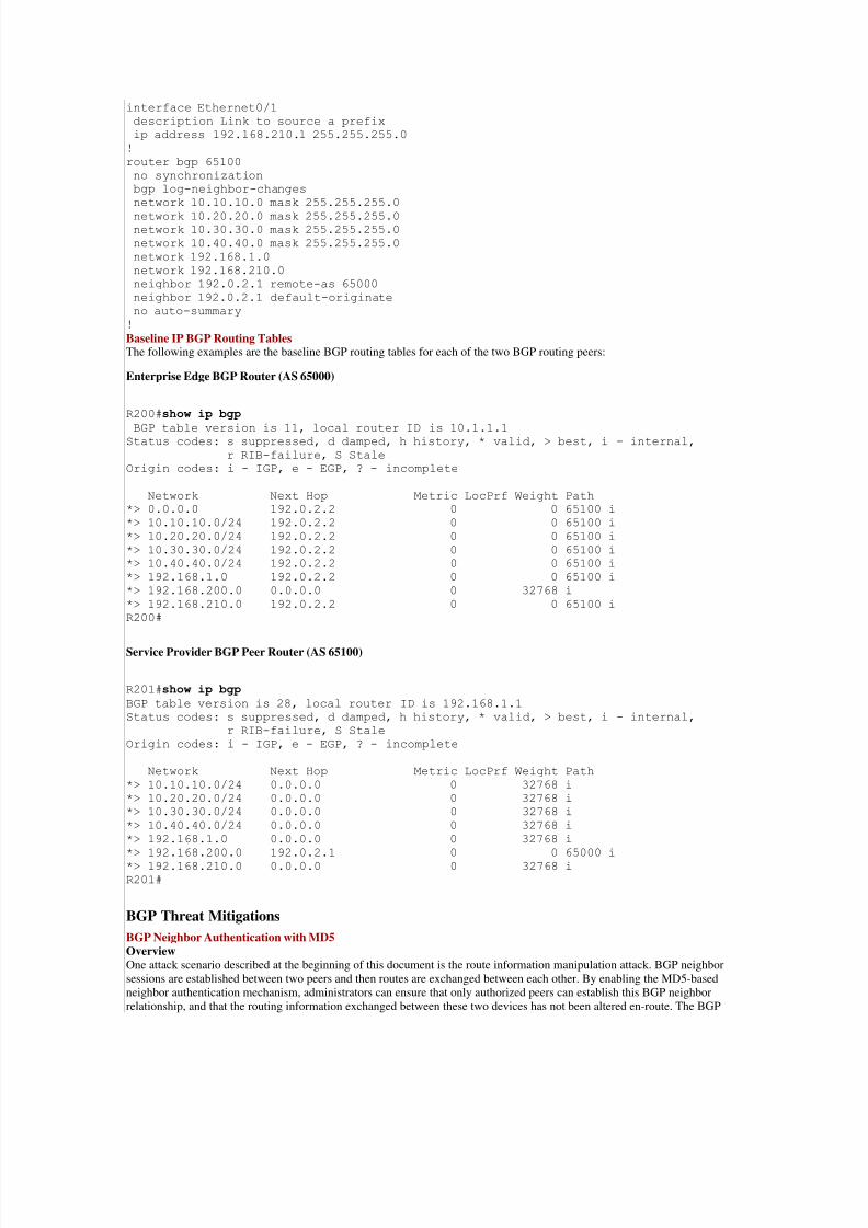
Baseline IP BGP Routing TablesThe following examples are the baseline BGP routing tables for each of the two BGP routing peers:
Enterprise Edge BGP Router (AS 65000)
R200#show ip bgp
BGP table version is 11, local router ID is 10.1.1.1Status codes: s suppressed, d damped, h history, * valid, > best, i - internal,
r RIB-failure, S Stale
Origin codes: i - IGP, e - EGP, ? - incomplete
Network Next Hop Metric LocPrf Weight Path
*> 0.0.0.0 192.0.2.2 0 0 65100 i
*> 10.10.10.0/24 192.0.2.2 0 0 65100 i
*> 10.20.20.0/24 192.0.2.2 0 0 65100 i
*> 10.30.30.0/24 192.0.2.2 0 0 65100 i
*> 10.40.40.0/24 192.0.2.2 0 0 65100 i
*> 192.168.1.0 192.0.2.2 0 0 65100 i
*> 192.168.200.0 0.0.0.0 0 32768 i
*> 192.168.210.0 192.0.2.2 0 0 65100 i
R200#
Service Provider BGP Peer Router (AS 65100)
R201#show ip bgp
BGP table version is 28, local router ID is 192.168.1.1
Status codes: s suppressed, d damped, h history, * valid, > best, i - internal,
r RIB-failure, S Stale
Origin codes: i - IGP, e - EGP, ? - incomplete
Network Next Hop Metric LocPrf Weight Path
*> 10.10.10.0/24 0.0.0.0 0 32768 i
*> 10.20.20.0/24 0.0.0.0 0 32768 i
*> 10.30.30.0/24 0.0.0.0 0 32768 i
*> 10.40.40.0/24 0.0.0.0 0 32768 i
*> 192.168.1.0 0.0.0.0 0 32768 i
*> 192.168.200.0 192.0.2.1 0 0 65000 i
*> 192.168.210.0 0.0.0.0 0 32768 i
R201#
BGP Threat Mitigations
BGP Neighbor Authentication with MD5
OverviewOne attack scenario described at the beginning of this document is the route information manipulation attack. BGP neighbor
sessions are established between two peers and then routes are exchanged between each other. By enabling the MD5-based
neighbor authentication mechanism, administrators can ensure that only authorized peers can establish this BGP neighbor
relationship, and that the routing information exchanged between these two devices has not been altered en-route. The BGP
7/29/2019 Protecting Border Gateway Protocol for the Enterprise
http://slidepdf.com/reader/full/protecting-border-gateway-protocol-for-the-enterprise 4/19
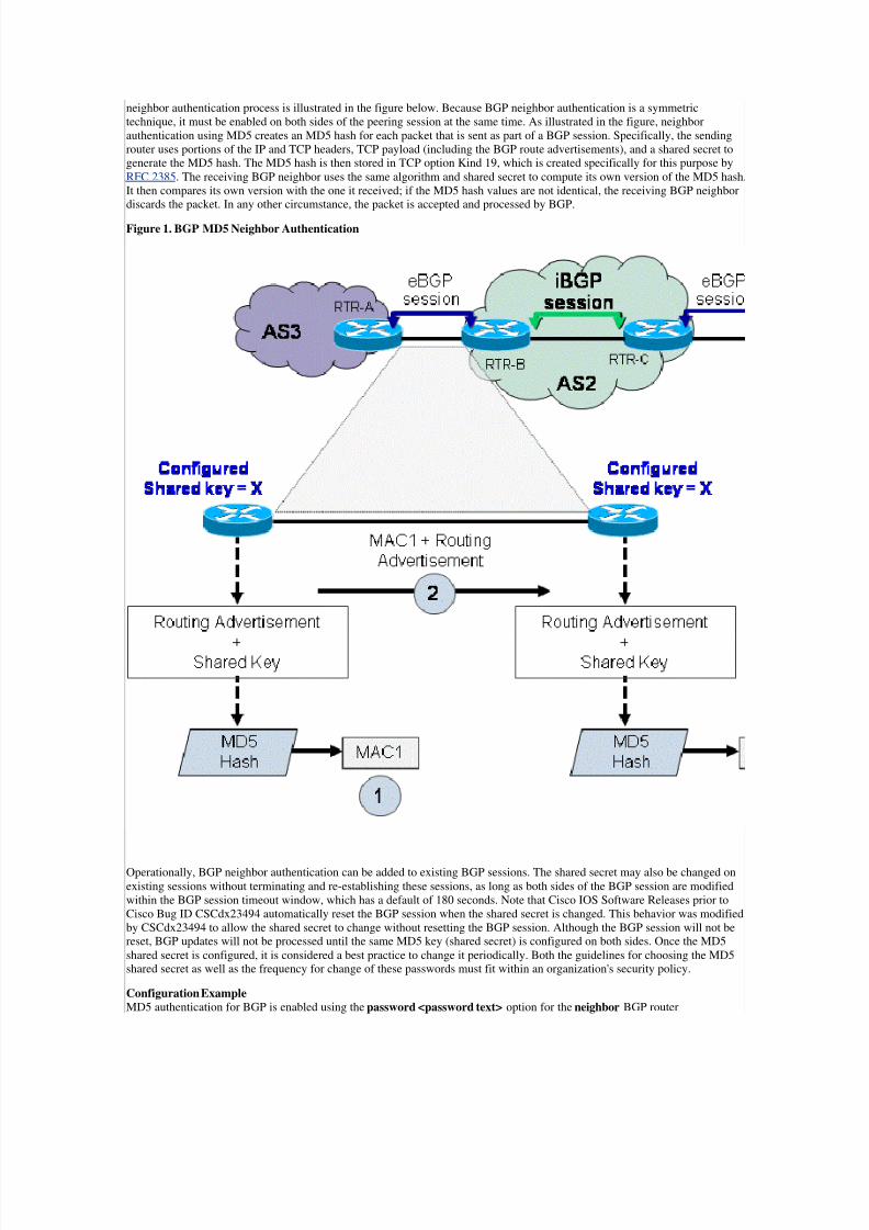
neighbor authentication process is illustrated in the figure below. Because BGP neighbor authentication is a symmetric
technique, it must be enabled on both sides of the peering session at the same time. As illustrated in the figure, neighbor
authentication using MD5 creates an MD5 hash for each packet that is sent as part of a BGP session. Specifically, the sending
router uses portions of the IP and TCP headers, TCP payload (including the BGP route advertisements), and a shared secret togenerate the MD5 hash. The MD5 hash is then stored in TCP option Kind 19, which is created specifically for this purpose by
RFC 2385. The receiving BGP neighbor uses the same algorithm and shared secret to compute its own version of the MD5 hash.
It then compares its own version with the one it received; if the MD5 hash values are not identical, the receiving BGP neighbordiscards the packet. In any other circumstance, the packet is accepted and processed by BGP.
Figure 1. BGP MD5 Neighbor Authentication
Operationally, BGP neighbor authentication can be added to existing BGP sessions. The shared secret may also be changed on
existing sessions without terminating and re-establishing these sessions, as long as both sides of the BGP session are modified
within the BGP session timeout window, which has a default of 180 seconds. Note that Cisco IOS Software Releases prior to
Cisco Bug ID CSCdx23494 automatically reset the BGP session when the shared secret is changed. This behavior was modified
by CSCdx23494 to allow the shared secret to change without resetting the BGP session. Although the BGP session will not bereset, BGP updates will not be processed until the same MD5 key (shared secret) is configured on both sides. Once the MD5
shared secret is configured, it is considered a best practice to change it periodically. Both the guidelines for choosing the MD5shared secret as well as the frequency for change of these passwords must fit within an organization's security policy.
Configuration ExampleMD5 authentication for BGP is enabled using the password <password text> option for the neighbor BGP router

7/29/2019 Protecting Border Gateway Protocol for the Enterprise
http://slidepdf.com/reader/full/protecting-border-gateway-protocol-for-the-enterprise 5/19
configuration command. The following example illustrates the configuration of this feature:
Enterprise Edge BGP Router (AS 65000)
!
interface Loopback0
description Loopback Interface used for non-BGP purposes
ip address 10.1.1.1 255.255.255.0!
interface Ethernet0/0
description Interface to Service Provider BGP Router
ip address 192.0.2.1 255.255.255.0
!
interface Ethernet0/1
description Interface to Enterprise Internal Network
ip address 192.168.200.1 255.255.255.0
!
router bgp 65000
no synchronization
bgp log-neighbor-changes
network 192.168.200.0
neighbor 192.0.2.2 remote-as 65100
neighbor 192.0.2.2 password C!SC)
no auto-summary!
Service Provider BGP Peer Router (AS 65100)
!
interface Loopback0
description Link to source a prefix
ip address 192.168.1.1 255.255.255.0
!
interface Loopback1
description Link to source a prefix
ip address 10.10.10.10 255.255.255.0
!
interface Loopback2
description Link to source a prefix
ip address 10.20.20.20 255.255.255.0!
interface Loopback3
description Link to source a prefix
ip address 10.30.30.30 255.255.255.0
!
interface Loopback4
description Link to source a prefix
ip address 10.40.40.40 255.255.255.0
!
interface Ethernet0/0
description Link to Enterprise BGP Router
ip address 192.0.2.2 255.255.255.0
!
interface Ethernet0/1
description Link to source a prefix
ip address 192.168.210.1 255.255.255.0
!
router bgp 65100
no synchronization
bgp log-neighbor-changes
network 10.10.10.0 mask 255.255.255.0
network 10.20.20.0 mask 255.255.255.0
network 10.30.30.0 mask 255.255.255.0
network 10.40.40.0 mask 255.255.255.0
network 192.168.1.0
network 192.168.210.0

7/29/2019 Protecting Border Gateway Protocol for the Enterprise
http://slidepdf.com/reader/full/protecting-border-gateway-protocol-for-the-enterprise 6/19
neighbor 192.0.2.1 remote-as 65000
neighbor 192.0.2.1 password C!SC) neighbor 192.0.2.1 default-originate
no auto-summary
!
Verification Example
As the following examples show, a network administrator can examine the output of the TCP Transmission Control Block (TCB) address to verify that a BGP neighbor session is using MD5 authentication.
BGP Neighbor Authentication When MD5 is Enabled
R200#show tcp brief
TCB Local Address Foreign Address (state)
05E29840 192.0.2.1.13297 192.0.2.2.179 ESTAB
R200#show tcp tcb 05E29840
Connection state is ESTAB, I/O status: 1, unread input bytes: 0
Connection is ECN Disabled, Mininum incoming TTL 254, Outgoing TTL 255
Local host: 192.0.2.1, Local port: 13297 Foreign host: 192.0.2.2, Foreign port: 179 ---output removed for brevity---
SRTT: 300 ms, RTTO: 303 ms, RTV: 3 ms, KRTT: 0 ms
minRTT: 0 ms, maxRTT: 368 ms, ACK hold: 200 ms
Status Flags: active open
Option Flags: nagle, path mtu capable, md5 ---output truncated---
The presence of md5 in the preceding Option Flags output indicates that BGP neighbor authentication with MD5 is now enabled
between these two BGP peers.
BGP Neighbor Authentication When MD5 is Not Enabled
R200#show tcp brief
TCB Local Address Foreign Address (state)
04F852C0 192.0.2.1.55407 192.0.2.2.179 ESTAB
R200#show tcp tcb 04F852C0 Connection state is ESTAB, I/O status: 1, unread input bytes: 0
Connection is ECN Disabled, Mininum incoming TTL 254, Outgoing TTL 255
Local host: 192.0.2.1, Local port: 55407 Foreign host: 192.0.2.2, Foreign port: 179
---output removed for brevity---
SRTT: 99 ms, RTTO: 1539 ms, RTV: 1440 ms, KRTT: 0 ms
minRTT: 4 ms, maxRTT: 300 ms, ACK hold: 200 ms
Status Flags: active open
Option Flags: nagle, path mtu capable ---output truncated---
The absence of the md5 flag in the preceding Option Flags output indicates that BGP neighbor authentication with MD5 is not
currently enabled between these two BGP peers.
Troubleshooting Examples
If BGP neighbor authentication is incorrectly configured (for example, it is either configured on only one peer or the MD5shared secret (password) does not match on both peers), the following types of syslog messages will be generated:
No Password Set on Remote Peer
Dec 3 15:01:52: %TCP-6-BADAUTH: No MD5 digest from 192.0.2.2(179) to 192.0.2.1(51954)
Incorrect Password Set on Remote Peer
Dec 3 15:01:57: %TCP-6-BADAUTH: Invalid MD5 digest from 192.0.2.2(22285) to

7/29/2019 Protecting Border Gateway Protocol for the Enterprise
http://slidepdf.com/reader/full/protecting-border-gateway-protocol-for-the-enterprise 7/19
192.0.2.1(179)
Refer to Neighbor Router Authentication for more information about BGP peer authentication with MD5.
BGP Time To Live Security CheckOverviewAnother BGP attack scenario that is listed at the beginning of this document is a Denial of Service (DoS) attack against the BGP
process. The BGP Time To Live (TTL) security check is designed to protect the BGP process from these kinds of CPU-
utilization-based attacks and route manipulation attempts. The BGP protocol must be examined in greater detail to understandhow this protection technique works.
The BGP protocol defines two types of sessions: internal BGP sessions (iBGP), which are established between peers within the
same Autonomous System (AS), and external BGP sessions (eBGP), which are established between peers in two different ASs.
eBGP sessions are the BGP sessions that are established between an Enterprise and its upstream SP.
By default and per the RFC, when eBGP is configured, the IP header TTL for all neighbor session packets is set to 1. This
setting was originally assumed to be useful because it prevents the establishment of an eBGP session beyond a single hop.However, an attacker could be located up to 255 hops away and still send spoofed packets to the BGP-speaking router
successfully. For example, an attacker could send large amounts of TCP SYN packets to the BGP peer in hopes of
overwhelming the BGP process. The BGP MD5 neighbor authentication technique described earlier in this document does not
protect against this kind of attack and can actually exacerbate its effects by causing the router CPU to expend resources while it
attempts to compute MD5 hashes on large numbers of attack packets. Therefore, another mechanism was required to defendagainst BGP DoS attacks. The BGP TTL check uses a clever modification to the original BGP RFC to accomplish this goal.
The BGP TTL security check leverages the fact that the vast majority of Internet SP eBGP peering sessions are established
between routers that are adjacent to each other (for example, either between directly connected interfaces or possibly betweenloopbacks). Because successful TTL spoofing is considered nearly impossible, a mechanism that is based on an expected TTLvalue was developed to provide a simple, robust defense from infrastructure attacks that are based on forged BGP packets. The
concept was originally defined and subsequently modified in the following documents: BGP TTL Security Hack (BTSH) andBGP in The Generalized TTL Security Mechanism (GTSM) .
When the BGP TTL security check is enabled, the initial TTL value for an eBGP packet is set to 255 rather than 1, and a"minimum TTL-value" is enforced on all BGP packets that are associated with that eBGP session. Because the IP header TTL
value is decremented by each router hop along its path to its final destination, the diameter from which an attacker couldpossibly source packets is restricted to those routers that are directly connected.
The BGP TTL security check is not required nor is it considered useful for iBGP sessions. The BGP TTL security check was
first introduced in Cisco IOS Software Releases 12.0(27)S, 12.3(7)T, and 12.2(25)S.Refer to BGP Support for TTL Security Check for more information.
Configuration Example
BGP TTL security check is enabled using the ttl-security option for the neighbor BGP router configuration command. Thefollowing example illustrates the configuration of this feature:
Enterprise Edge BGP Router (AS 65000)
!
interface Loopback0
description Loopback Interface used for non-BGP purposes
ip address 10.1.1.1 255.255.255.0
!
interface Ethernet0/0
description Interface to Service Provider BGP Router
ip address 192.0.2.1 255.255.255.0
!
interface Ethernet0/1
description Interface to Enterprise Internal Network
ip address 192.168.200.1 255.255.255.0
!
router bgp 65000
no synchronization
bgp log-neighbor-changes
network 192.168.200.0
neighbor 192.0.2.2 remote-as 65100
neighbor 192.0.2.2 ttl-security hops 1
no auto-summary
!
7/29/2019 Protecting Border Gateway Protocol for the Enterprise
http://slidepdf.com/reader/full/protecting-border-gateway-protocol-for-the-enterprise 8/19
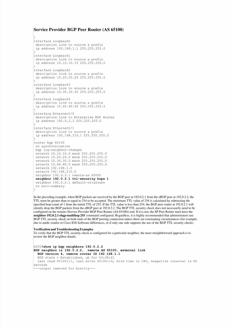
Service Provider BGP Peer Router (AS 65100)
!
interface Loopback0
description Link to source a prefix
ip address 192.168.1.1 255.255.255.0
!
interface Loopback1
description Link to source a prefix
ip address 10.10.10.10 255.255.255.0
!
interface Loopback2
description Link to source a prefix
ip address 10.20.20.20 255.255.255.0
!
interface Loopback3
description Link to source a prefix
ip address 10.30.30.30 255.255.255.0
!
interface Loopback4
description Link to source a prefix
ip address 10.40.40.40 255.255.255.0
!
interface Ethernet0/0description Link to Enterprise BGP Router
ip address 192.0.2.2 255.255.255.0
!
interface Ethernet0/1
description Link to source a prefix
ip address 192.168.210.1 255.255.255.0
!
router bgp 65100
no synchronization
bgp log-neighbor-changes
network 10.10.10.0 mask 255.255.255.0
network 10.20.20.0 mask 255.255.255.0
network 10.30.30.0 mask 255.255.255.0
network 10.40.40.0 mask 255.255.255.0
network 192.168.1.0
network 192.168.210.0neighbor 192.0.2.1 remote-as 65000
neighbor 192.0.2.1 ttl-security hops 1
neighbor 192.0.2.1 default-originate
no auto-summary
!
In the preceding example, when BGP packets are received by the BGP peer at 192.0.2.1 from the eBGP peer at 192.0.2.2, the
TTL must be greater than or equal to 254 to be accepted. The minimum TTL value of 254 is calculated by subtracting the
specified hop-count of 1 from the initial TTL of 255. If the TTL value is less than 254, the BGP peer router at 192.0.2.1 will
silently drop the BGP packets from the eBGP peer at 192.0.2.2. The BGP TTL security check does not necessarily need to be
configured on the remote (Service Provider BGP Peer Router (AS 65100)) end. If it is not, the SP Peer Router must have the
neighbor 192.0.2.1 ebgp-multihop 255 command configured. Regardless, it is highly recommended that administrators use
BGP TTL security check on both ends of the BGP peering connection unless there are extenuating circumstances (for example,
due to multi-vendor or Cisco IOS Software differences, or if only one side supports the use of the BGP TTL security check).
Verification and Troubleshooting ExamplesTo verify that the BGP TTL security check is configured for a particular neighbor, the most straightforward approach is toreview the BGP neighbor details:
R200#show ip bgp neighbors 192.0.2.2 BGP neighbor is 192.0.2.2, remote AS 65100, external linkBGP version 4, remote router ID 192.168.1.1 BGP state = Established, up for 03:28:41
Last read 00:00:11, last write 00:00:14, hold time is 180, keepalive interval is 60
seconds
---output removed for brevity---

7/29/2019 Protecting Border Gateway Protocol for the Enterprise
http://slidepdf.com/reader/full/protecting-border-gateway-protocol-for-the-enterprise 9/19
External BGP neighbor may be up to 1 hop away.
Transport(tcp) path-mtu-discovery is enabled
Connection state is ESTAB, I/O status: 1, unread input bytes: 0
Connection is ECN Disabled, Mininum incoming TTL 254, Outgoing TTL 255
Local host: 192.0.2.1, Local port: 55407
Foreign host: 192.0.2.2, Foreign port: 179
---output truncated---
Refer to BGP Support for TTL Security Check for more information.
Configuring Maximum Prefixes
OverviewAnother BGP concern addressed at the beginning of this document is the inadvertent misconfiguration of BGP neighbors, which
can have potentially unintended consequences to existing BGP sessions. The previous mitigation techniques are intended to
prevent unauthorized packets from affecting the BGP process; however, when a legitimate eBGP peer is misconfigured, neithertechnique will prevent the BGP process from being disrupted. BGP may cause a disruption by attempting to install too many
routes in its routing table.
BGP prefixes are stored in router memory, and the more BGP prefixes that a router must store, the more memory is consumed.
In some BGP configurations, a subset of all Internet prefixes can be stored, such as when only a default route or routes for a
provider's customer networks are required. In other cases, the entire Internet routing table may be needed. (The January 2009
version of the CIDR Report recorded 284,121 prefixes in the Internet Routing Table.) In many cases, due to CPU or memory
limitations, a Cisco IOS device cannot accept the amount of prefixes that is contained in the Internet routing table. In addition,inadvertent configurations have been known to cause route de-aggregation, which can cause a rapid increase in the number of
prefixes that the BGP process encounters. To prevent CPU or memory exhaustion, administrators are advised to considerconfiguring the maximum number of prefixes that can be accepted on a per-neighbor basis.
The BGP maximum prefix feature allows administrators to control the number of prefixes that can be installed from a neighbor.When configured, this feature will terminate a neighbor relationship when the number of received prefixes from the peer
exceeds the configured maximum prefix limit. Although this feature is commonly used for external BGP peers, it can also beapplied to internal BGP peers.
To effectively configure this feature, the normal maximum expected number of routes should be well known and understood.
Typically, the maximum prefix threshold would be set slightly higher to accommodate unexpected changes. In addition, it may
be useful to modify the default behavior of resetting the eBGP session because it can be disruptive to traffic flow. Another
option involves logging a warning message when the threshold is exceeded.
Note: An enhancement to this feature that was introduced in Cisco IOS Software Releases 12.0(22)S and 12.2(15)T allows the
automatic reestablishment of a peering session that was terminated when the configured maximum prefix limit was exceeded.No intervention from the network operator is required when this feature is enabled.
Configuration ExampleWhen configuring this feature by using the neighbor maximum-prefix BGP router configuration command, at least one
argument is required, which is the maximum number of prefixes that are accepted before a peer is shutdown. In addition, thefollowing optional parameters can be configured after the number of maximum prefixes to be accepted.
Threshold Value – the percentage at which to generate a warning message, which ranges between 1 – 100 %
Restart Interval – the amount of time in minutes (between 1 – 65535) after which the terminated BGP connection will berestarted
Warning-only – a syslog warning message that will be generated once the prefix limit is exceeded (the BGP connection willnot be terminated)
The following maximum-prefix command will set a limit of five prefixes to be received from the BGP peer at 192.0.2.2. Oncefour prefixes are received (for example, greater than 70 percent of five), a warning message will be issued. Once the limit of five
prefixes has been reached, the BGP session will be terminated and restarted in 30 minutes.
neighbor 192.0.2.2 maximum-prefix 5 70 restart 30
In the following configuration, the maximum number of prefixes that will be accepted by the Local BGP Router is five. Once
the number of prefixes that are received from the BGP peer at 192.0.2.2 exceeds five, a log message will be generated, and theBGP neighbor relationship will be terminated.
Enterprise Edge BGP Router (AS 65000)
!
7/29/2019 Protecting Border Gateway Protocol for the Enterprise
http://slidepdf.com/reader/full/protecting-border-gateway-protocol-for-the-enterprise 10/19
interface Loopback0
description Loopback Interface used for non-BGP purposes
ip address 10.1.1.1 255.255.255.0
!
interface Ethernet0/0
description Interface to Service Provider BGP Router
ip address 192.0.2.1 255.255.255.0
!
interface Ethernet0/1description Interface to Enterprise Internal Network
ip address 192.168.200.1 255.255.255.0
!
router bgp 65000
no synchronization
bgp log-neighbor-changes
network 192.168.200.0
neighbor 192.0.2.2 remote-as 65100
neighbor 192.0.2.2 maximum-prefix 5
no auto-summary
!
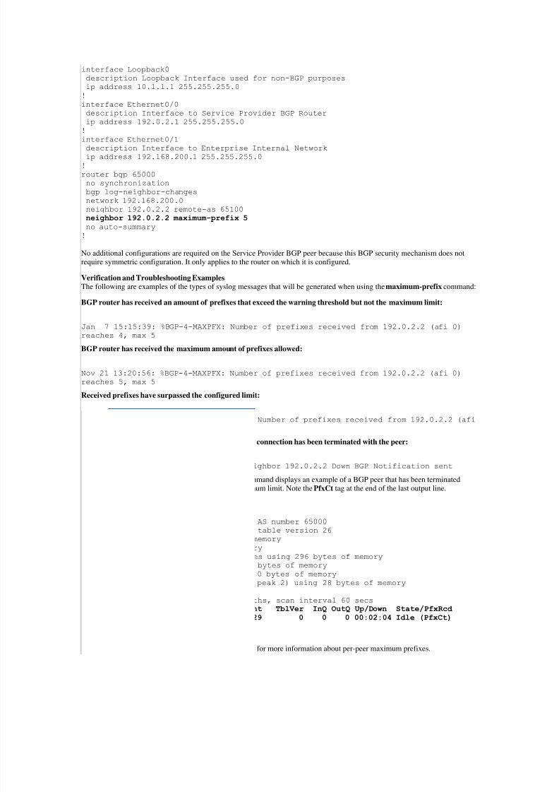
No additional configurations are required on the Service Provider BGP peer because this BGP security mechanism does notrequire symmetric configuration. It only applies to the router on which it is configured.
Verification and Troubleshooting ExamplesThe following are examples of the types of syslog messages that will be generated when using the maximum-prefix command:
BGP router has received an amount of prefixes that exceed the warning threshold but not the maximum limit:
Jan 7 15:15:39: %BGP-4-MAXPFX: Number of prefixes received from 192.0.2.2 (afi 0)
reaches 4, max 5
BGP router has received the maximum amount of prefixes allowed:
Nov 21 13:20:56: %BGP-4-MAXPFX: Number of prefixes received from 192.0.2.2 (afi 0)
reaches 5, max 5
Received prefixes have surpassed the configured limit:
Nov 21 13:20:56: %BGP-3-MAXPFXEXCEED: Number of prefixes received from 192.0.2.2 (afi
0): 6 exceeds limit 5
After too many prefixes have been received, the BGP connection has been terminated with the peer:
Nov 21 13:20:56: %BGP-5-ADJCHANGE: neighbor 192.0.2.2 Down BGP Notification sent
The following output of the show ip bgp summary command displays an example of a BGP peer that has been terminatedbecause the number of prefixes has exceeded the maximum limit. Note the PfxCt tag at the end of the last output line.
R200#show ip bgp summary
BGP router identifier 10.1.1.1, local AS number 65000
BGP table version is 26, main routing table version 26
1 network entries using 132 bytes of memory
1 path entries using 52 bytes of memory
2/1 BGP path/bestpath attribute entries using 296 bytes of memory0 BGP route-map cache entries using 0 bytes of memory
0 BGP filter-list cache entries using 0 bytes of memory
Bitfield cache entries: current 1 (at peak 2) using 28 bytes of memory
BGP using 508 total bytes of memory
BGP activity 24/23 prefixes, 24/23 paths, scan interval 60 secs
Neighbor V AS MsgRcvd MsgSent TblVer InQ OutQ Up/Down State/PfxRcd 192.0.2.2 4 65100 20335 20329 0 0 0 00:02:04 Idle (PfxCt) R200#
Refer to Configuring the BGP Maximum-Prefix Feature for more information about per-peer maximum prefixes.
7/29/2019 Protecting Border Gateway Protocol for the Enterprise
http://slidepdf.com/reader/full/protecting-border-gateway-protocol-for-the-enterprise 11/19
Filtering BGP Prefixes with Prefix Lists
OverviewIn addition to restricting the maximum number prefixes that BGP is allowed to install, another important BGP session protection
mechanism is the individual filtering of prefixes to prevent BGP from inadvertently installing unwanted or illegal prefixes in therouting table. Whether due to malicious intent or simple misconfiguration, prefix filtering should be configured to allow a
network administrator to permit or deny specific prefixes that are sent to or received from each BGP peer. This configuration
ensures that network traffic is sent over the intended paths. Prefix lists should be applied to each eBGP peer in both inbound and
outbound directions. Prefix lists can be configured to specifically allow only those prefixes that are permitted by the routing
policy of a network, which is an example of white list-based filtering. If this configuration is not feasible due to the largenumber of prefixes that are received, a prefix list can be configured to specifically block known undesirable prefixes (a
technique known as black list filtering). These prefixes should include unallocated IP address space and networks that are
reserved by RFC 3330 for special use, such as for internal or testing purposes. Outbound prefix lists should be configured to
specifically permit only the prefixes that an organization intends to advertise. For the same reason best practices recommend that
access control lists (ACLs) deny packets that use special-use addressing and packets that are sourced from addresses belonging
to the enterprise IP address space, inbound and outbound prefix lists should, either explicitly or implicitly, prevent receipt andtransmission of IP address space that is referenced by the following RFCs:
RFC 1918, which defines reserved address space that is not a valid source address on the Internet
RFC 2827, which provides anti-spoofing guidelines
RFC 3330, which defines special-use addresses that might require filtering
Configuration Example
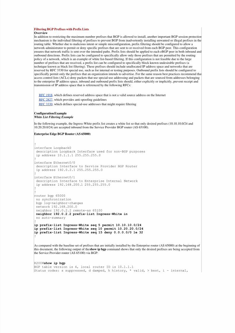
White List Filtering Example
In the following example, the Ingress-White prefix list creates a white list so that only desired prefixes (10.10.10.0/24 and10.20.20.0/24) are accepted inbound from the Service Provider BGP router (AS 65100).
Enterprise Edge BGP Router (AS 65000)
!
interface Loopback0
description Loopback Interface used for non-BGP purposes
ip address 10.1.1.1 255.255.255.0
!
interface Ethernet0/0
description Interface to Service Provider BGP Router
ip address 192.0.2.1 255.255.255.0
!interface Ethernet0/1
description Interface to Enterprise Internal Network
ip address 192.168.200.1 255.255.255.0
!
!
router bgp 65000
no synchronization
bgp log-neighbor-changes
network 192.168.200.0
neighbor 192.0.2.2 remote-as 65100
neighbor 192.0.2.2 prefix-list Ingress-White in no auto-summary
!
ip prefix-list Ingress-White seq 5 permit 10.10.10.0/24ip prefix-list Ingress-White seq 10 permit 10.20.20.0/24
ip prefix-list Ingress-White seq 15 deny 0.0.0.0/0 le 32 !
As compared with the baseline set of prefixes that are initially installed by the Enterprise router (AS 65000) at the beginning of
this document, the following output of the show ip bgp command shows that only the desired prefixes are being accepted fromthe Service Provider router (AS 65100) via BGP:
R200#show ip bgp
BGP table version is 4, local router ID is 10.1.1.1
Status codes: s suppressed, d damped, h history, * valid, > best, i - internal,
7/29/2019 Protecting Border Gateway Protocol for the Enterprise
http://slidepdf.com/reader/full/protecting-border-gateway-protocol-for-the-enterprise 12/19
r RIB-failure, S Stale
Origin codes: i - IGP, e - EGP, ? - incomplete
Network Next Hop Metric LocPrf Weight Path
*> 10.10.10.0/24 192.0.2.2 0 0 65100 i *> 10.20.20.0/24 192.0.2.2 0 0 65100 i *> 192.168.200.0 0.0.0.0 0 32768 i
R200#
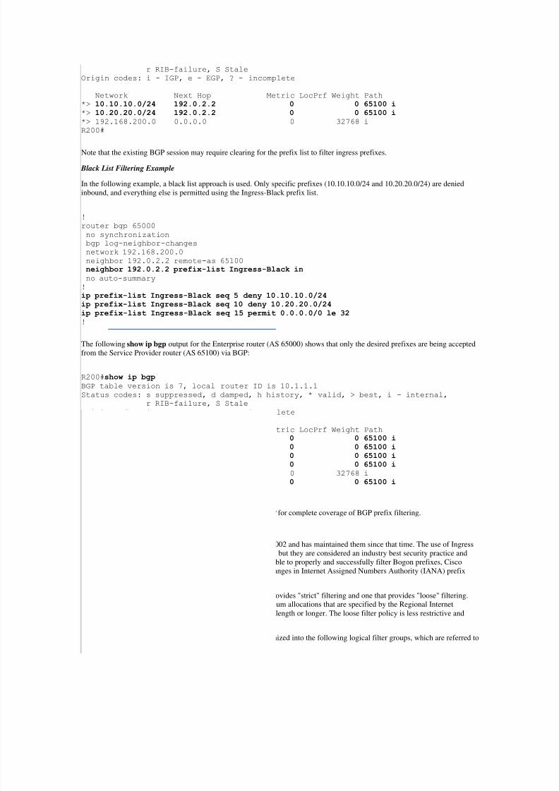
Note that the existing BGP session may require clearing for the prefix list to filter ingress prefixes.
Black List Filtering Example
In the following example, a black list approach is used. Only specific prefixes (10.10.10.0/24 and 10.20.20.0/24) are denied
inbound, and everything else is permitted using the Ingress-Black prefix list.
!
router bgp 65000
no synchronization
bgp log-neighbor-changes
network 192.168.200.0
neighbor 192.0.2.2 remote-as 65100
neighbor 192.0.2.2 prefix-list Ingress-Black in
no auto-summary!
ip prefix-list Ingress-Black seq 5 deny 10.10.10.0/24ip prefix-list Ingress-Black seq 10 deny 10.20.20.0/24ip prefix-list Ingress-Black seq 15 permit 0.0.0.0/0 le 32
!
The following show ip bgp output for the Enterprise router (AS 65000) shows that only the desired prefixes are being accepted
from the Service Provider router (AS 65100) via BGP:
R200#show ip bgp
BGP table version is 7, local router ID is 10.1.1.1
Status codes: s suppressed, d damped, h history, * valid, > best, i - internal,
r RIB-failure, S Stale
Origin codes: i - IGP, e - EGP, ? - incomplete
Network Next Hop Metric LocPrf Weight Path*> 0.0.0.0 192.0.2.2 0 0 65100 i *> 10.30.30.0/24 192.0.2.2 0 0 65100 i *> 10.40.40.0/24 192.0.2.2 0 0 65100 i *> 192.168.1.0 192.0.2.2 0 0 65100 i *> 192.168.200.0 0.0.0.0 0 32768 i
*> 192.168.210.0 192.0.2.2 0 0 65100 i R200#
Refer to Connecting to a Service Provider Using External BGP for complete coverage of BGP prefix filtering.
Ingress Prefix Filter Templates
Cisco initially created and published Ingress Prefix Filters in 2002 and has maintained them since that time. The use of Ingress
Prefix Filters is not mandated or required by Standards Bodies, but they are considered an industry best security practice andCisco advocates their usage. To ensure that organizations are able to properly and successfully filter Bogon prefixes, Cisco
continues to provide updates to the Ingress Prefix Filters as changes in Internet Assigned Numbers Authority (IANA) prefixallocations and other modifications dictate.
Cisco maintains two types of Ingress Prefix Filters, one that provides "strict" filtering and one that provides "loose" filtering.The strict filter policy restricts prefixes according to the minimum allocations that are specified by the Regional Internet
Registries (RIRs), which are typically allocated to a /20 prefix length or longer. The loose filter policy is less restrictive andgenerally enforces a minimum prefix length of /24.
Strict and loose Ingress Prefix Filter policy templates are organized into the following logical filter groups, which are referred toas phases:
7/29/2019 Protecting Border Gateway Protocol for the Enterprise
http://slidepdf.com/reader/full/protecting-border-gateway-protocol-for-the-enterprise 13/19
Phase 1 – Deny Special Prefixes (1 – 99)
Phase 2 – Deny Your Own Prefixes (100 – 199)
Phase 3 – Deny IXP Prefixes (200 – 299)
Phase 4 – Deny Bogon Prefixes (300 – 399)
Phase 5 – Permit Critical Infrastructure Prefixes (400 – 699)
Phase 6 – Permit RIR Prefixes On The Minimum Allocation That Is Advertised by the RIR for the 'Strict Filter' or Permit
RIR Prefixes On The Minimum Allocation To A /24 for the 'Loose Filter' (4000 –
8999)
Phase 7 – Permit The Rest Between /8 and /24 (10000 – 10999)
Prefix Filter Modifications
Each time the IANA IPv4 registry is updated to reflect the allocation or deallocation of IPv4 address space, Cisco updates thestrict and loose Ingress Prefix Filter templates.
The current IANA IPv4 registry is available at the following link:http://www.iana.org/assignments/ipv4-address-space/ipv4-address-space.txt
The strict and loose Ingress Prefix Filter templates are available at the following link:
ftp://ftp-eng.cisco.com/cons/isp/security/Ingress-Prefix-Filter-Templates
Note: The ftp-eng.cisco.com domain requires passive FTP from inside the Cisco network.
Update Notifications and Mailing List
An externally available mailing list has been created to allow interested parties to subscribe and receive notifications each timethe strict and loose Ingress Prefix Filter templates have been updated to reflect a prefix allocation to an RIR, prefix deallocation
from an RIR, or a prefix change in the IANA IPv4 registry.
To join to the strict and loose Ingress Prefix Filter templates announce mailing list, send an e-mail message to ipv4-ingress-
[email protected]. Once the subscription request has been received, you will recieve a confirmation e-mailmessage to confirm you are interested in subscribing to the mailing list. Interested parties must respond to this confirmation
message to receive announcement notifications. Once you have been successfully subscribed to the mailing list, you will receivea welcome message that contains your subscription information. Save this message for future reference should you need to
unsubscribe from the mailing list.
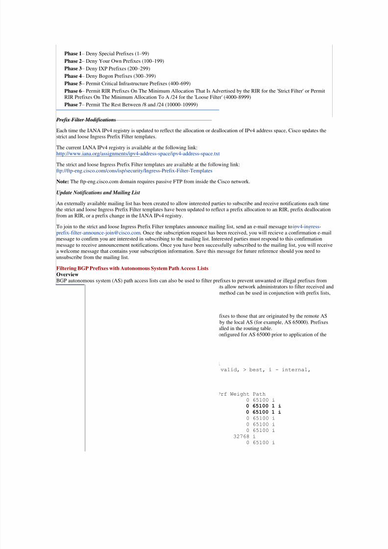
Filtering BGP Prefixes with Autonomous System Path Access Lists
OverviewBGP autonomous system (AS) path access lists can also be used to filter prefixes to prevent unwanted or illegal prefixes from
inadvertently being installed in the routing table by BGP. AS path access lists allow network administrators to filter received andadvertised prefixes based on the AS path attribute of a prefix. This filtering method can be used in conjunction with prefix lists,which filter based on prefix, to establish a robust set of BGP route filters.
Configuration ExampleThis configuration example uses AS path access lists to restrict inbound prefixes to those that are originated by the remote AS
(for example, AS 65100) and outbound prefixes to those that are originated by the local AS (for example, AS 65000). Prefixes
that are sourced from all other autonomous systems are filtered and not installed in the routing table.
The following example shows the show ip bgp output of the router that is configured for AS 65000 prior to application of theAS path list:
R200#show ip bgp
BGP table version is 1, local router ID is 10.1.1.1
Status codes: s suppressed, d damped, h history, * valid, > best, i - internal,
r RIB-failure, S Stale
Origin codes: i - IGP, e - EGP, ? - incomplete
Network Next Hop Metric LocPrf Weight Path
* 0.0.0.0 192.0.2.2 0 0 65100 i
* 10.10.10.0/24 192.0.2.2 0 0 65100 1 i * 10.20.20.0/24 192.0.2.2 0 0 65100 1 i * 10.30.30.0/24 192.0.2.2 0 0 65100 i
* 10.40.40.0/24 192.0.2.2 0 0 65100 i
* 192.168.1.0 192.0.2.2 0 0 65100 i
* 192.168.200.0 0.0.0.0 0 32768 i
* 192.168.210.0 192.0.2.2 0 0 65100 i
R200#

7/29/2019 Protecting Border Gateway Protocol for the Enterprise
http://slidepdf.com/reader/full/protecting-border-gateway-protocol-for-the-enterprise 14/19
Note that the AS path of 65100 1 indicates that some of the routes appear to originate in AS 1. This scenario was accomplishedby configuring a route map on the router at AS 65100, which prepends certain outbound BGP routing updates (10.10.10.0/24
and 10.20.20.0/24) with an AS of 1 (see configuration below). This configuration will cause two specific BGP routes from this
router to appear as if they originate from AS 1, not AS 65100. The necessary configuration for the SP Provider BGP Peer Routeris shown in the following example:
Service Provider BGP Peer Router (AS 65100)
!
router bgp 65100
no synchronization
bgp log-neighbor-changes
network 10.10.10.0 mask 255.255.255.0
network 10.20.20.0 mask 255.255.255.0
network 10.30.30.0 mask 255.255.255.0
network 10.40.40.0 mask 255.255.255.0
network 192.168.1.0
network 192.168.210.0
neighbor 192.0.2.1 remote-as 65000
neighbor 192.0.2.1 default-originate
neighbor 192.0.2.1 route-map as-path out
no auto-summary
!
access-list 1 permit 10.10.10.0 0.0.0.255access-list 1 permit 10.20.20.0 0.0.0.255
!
route-map as-path permit 10 match ip address 1set as-path prepend 1
!
route-map as-path permit 20 !
The router that is configured for AS 65000 now has an AS path list that was applied to all inbound routing updates using the
filter-list command, which requires that the update originate from AS 65100.
router bgp 65000no synchronization
bgp log-neighbor-changes
network 192.168.200.0
neighbor 192.0.2.2 remote-as 65100
neighbor 192.0.2.2 filter-list 1 inneighbor 192.0.2.2 filter-list 2 out
no auto-summary
!
! The following as-path access-list filter restricts all
! incoming BGP routes to those that originated in AS 65100
ip as-path access-list 1 permit ^65100$ ! The following as-path access-list filter restricts all
! outgoing BGP routes to those that originated within the local (65000) AS
ip as-path access-list 2 permit ^$
!
With the above filter list applied to the router configured for AS 65000, no routes from the peer with AS 1 in its AS path arevisible:
R200#show ip bgp
BGP table version is 1, local router ID is 10.1.1.1
Status codes: s suppressed, d damped, h history, * valid, > best, i - internal,
r RIB-failure, S Stale
Origin codes: i - IGP, e - EGP, ? - incomplete

7/29/2019 Protecting Border Gateway Protocol for the Enterprise
http://slidepdf.com/reader/full/protecting-border-gateway-protocol-for-the-enterprise 15/19
Network Next Hop Metric LocPrf Weight Path
* 0.0.0.0 192.0.2.2 0 0 65100 i
* 10.30.30.0/24 192.0.2.2 0 0 65100 i
* 10.40.40.0/24 192.0.2.2 0 0 65100 i
* 192.168.1.0 192.0.2.2 0 0 65100 i
* 192.168.200.0 0.0.0.0 0 32768 i
* 192.168.210.0 192.0.2.2 0 0 65100 i
R200#
AS Path Length Limiting
OverviewIn addition to filtering routes based on specific AS paths (AS number), it is also possible to filter routes by limiting the number
of AS path segments that each route can include. This limiting is performed primarily to prevent the router from expending too
much memory when it stores routes with long AS paths. The bgp maxas-limit feature allows administrators to set a limit on the
number of AS path segments that are associated with any route. Administrators should note that because this feature is a routerconfiguration command that is not tied to any specific BGP neighbor, all neighbors will be treated uniformly according to the
specified policy. Prior to the functionality change for the Cisco bug associated with CSCee30718, the value that can be enteredfor this argument is a number from 1 to 255. Following the functionality change associated with CSCee30718, it is possible to
configure a higher threshold value (up to 2,000) for the AS path segment length. Advertising a route with an AS path length that
exceeds 255 may result in an adverse impact when sending long AS path segments to downstream BGP routers. Because CiscoIOS Software limits the prepending value to 10 using route maps, the most that a Cisco device could add is 21 AS identifiers, or
10 on ingress, 10 on egress, and 1 for normal BGP AS processing. An administrator can set the bgp maxas-limit to 234, whichresults in a maximum AS path length of 255 AS identifiers that can be sent to the downstream BGP peers. Using a conservative
value of 200 can simplify the configuration and also prevent this condition. Administrators are advised to configure and fullytest any limit in a lab environment prior to deployment on a production router. The bgp maxas-limit command was introducedin Cisco IOS Software Release 12.2 and in 12.0(17)S in the 12.0S train.
Please refer to the Team Cymru BGP/ASN Analysis Report for up-to-date information on the longest AS path length that iscurrently being advertised on the Internet.
Configuration ExampleTo configure BGP to discard routes with an AS path segment length that exceeds a specified value, use the bgp maxas-limitcommand in router configuration mode.
The following output of the show ip bgp command displays the BGP routes that are being accepted from the Service Provider
router (AS 65100) prior to configuring the bgp maxas-limit command. Note that the 65100 1 1 1 1 1 1 AS path length consistsof a total of seven AS path segments.
Router-Ent#show ip bgp
BGP table version is 1, local router ID is 10.1.1.1
Status codes: s suppressed, d damped, h history, * valid, > best, i - internal,
r RIB-failure, S Stale
Origin codes: i - IGP, e - EGP, ? - incomplete
Network Next Hop Metric LocPrf Weight Path
* 0.0.0.0 192.0.2.2 0 0 65100 i
* 10.10.10.0/24 192.0.2.2 0 0 65100 1 1 1 1 1 1 i * 10.20.20.0/24 192.0.2.2 0 0 65100 1 1 1 1 1 1 i * 10.30.30.0/24 192.0.2.2 0 0 65100 1 1 1 1 1 1 i * 10.40.40.0/24 192.0.2.2 0 0 65100 1 1 1 1 1 1 i * 192.168.1.0 192.0.2.2 0 0 65100 1 1 1 1 1 1 i * 192.168.210.0 192.0.2.2 0 0 65100 1 1 1 1 1 1 i
Router-Ent#
In the following configuration, the maximum length of the AS path that will be accepted is five segments. Once the number of AS path segments that are received exceeds five, the route will not be placed into the BGP routing table, and a log message willbe generated. Routes that are already installed are not affected. Only routes that are received in updates subsequent to
application of this configuration will be subjected to the policy.
Enterprise Edge BGP Router (AS 65000)
!
interface Loopback0
description Loopback Interface used for non-BGP purposes
ip address 10.1.1.1 255.255.255.0

7/29/2019 Protecting Border Gateway Protocol for the Enterprise
http://slidepdf.com/reader/full/protecting-border-gateway-protocol-for-the-enterprise 16/19
!
interface Ethernet0/0
description Interface to Service Provider BGP Router
ip address 192.0.2.1 255.255.255.0
!
interface Ethernet0/1
description Interface to Enterprise Internal Network
ip address 192.168.200.1 255.255.255.0
!
router bgp 65000
no synchronization
bgp log-neighbor-changes
bgp maxas-limit 5 network 192.168.200.0
neighbor 192.0.2.2 remote-as 65100
no auto-summary
!
No additional configurations are required on the Service Provider BGP peer because this BGP security mechanism does notrequire symmetric configuration. It only applies to the router on which it is configured.
Verification and Troubleshooting ExamplesThis following example is the syslog message that will be generated when the bgp maxas-limit command is used and the
number of AS path segments that are received exceeds the configured threshold:
Feb 17 12:22:24: %BGP-6-ASPATH: Long AS path 65100 1 1 1 1 1 1 received from
192.0.2.2: More than
configured MAXAS-LIMIT
The following show ip bgp output for the Enterprise router (AS 65000) shows that after clearing the BGP session, only theroutes with an AP path length of less than five are now being accepted from the Service Provider router (AS 65100) via BGP:
Router-Ent#show ip bgp BGP table version is 3, local router ID is 10.1.1.1
Status codes: s suppressed, d damped, h history, * valid, > best, i - internal,
r RIB-failure, S Stale
Origin codes: i - IGP, e - EGP, ? - incomplete
Network Next Hop Metric LocPrf Weight Path*> 0.0.0.0 192.0.2.2 0 0 65100 i
*> 192.168.200.0 0.0.0.0 0 32768 i
Router-Ent#
Refer to the bgp maxas-limit command for more information.
Infrastructure ACLs
OverviewTo protect infrastructure devices and minimize the risk, impact, and effectiveness of direct infrastructure attacks, administrators
are advised to deploy infrastructure ACLs (iACLs) to perform policy enforcement of traffic that is sent to infrastructureequipment. Administrators can construct an iACL by explicitly permitting only authorized BGP traffic that is sent to
infrastructure devices in accordance with existing security policies and configurations. Care should be taken to allow requiredtraffic for other routing and administrative access prior to denying all unauthorized traffic.
Configuration Example
Although the following iACL includes the filtering of certain IP address ranges from which infrastructure devices are notnormally expected to receive packets, it is neither an exhaustive ACL nor is it applicable all network environments. This iACL
serves as an example and should be modified and tested by each network administrator prior to deployment in productionenvironments. Because BGP mitigation is the focus of this document, the BGP-specific entries appear in bold text.
ip access-list extended Infrastructure-ACL-Policy
!--- Anti-spoofing entries are shown here.
!--- Deny special-use address sources.
!--- Refer to RFC 3330 for additional special use addresses.
deny ip host 0.0.0.0 any

7/29/2019 Protecting Border Gateway Protocol for the Enterprise
http://slidepdf.com/reader/full/protecting-border-gateway-protocol-for-the-enterprise 17/19
deny ip 127.0.0.0 0.255.255.255 any
deny ip 224.0.0.0 31.255.255.255 any
!--- Filter RFC 1918 space.
deny ip 10.0.0.0 0.255.255.255 any
deny ip 172.16.0.0 0.15.255.255 any
deny ip 192.168.0.0 0.0.255.255 any
!--- Deny your space as source from entering your AS.
!--- Deploy only at the AS edge.
deny ip 192.168.200.0 0.0.0.255 any!--- Permit known-good BGP peers permit tcp host 192.0.2.2 host 192.0.2.1 eq bgp permit tcp host 192.0.2.2 eq bgp host 192.0.2.1!--- Deny all other BGP packetsdeny tcp any any eq bgpdeny tcp any eq bgp any
!--- Deny access to internal infrastructure addresses.
deny ip any 192.168.200.0 0.0.0.255
!-- Permit/deny all other Layer 3 and Layer 4 traffic in accordance
!-- with existing security policies and configurations
!--- Permit transit traffic.
permit ip any any
!-- Apply iACL to interfaces in the ingress direction
!
interface Ethernet0/0
description Interface to Service Provider BGP Routerip address 192.0.2.1 255.255.255.0
ip access-group Infrastructure-ACL-Policy in
!
Additional information about iACLs is in Protecting Your Core: Infrastructure Protection Access Control Lists.
Control Plane Policing
OverviewControl Plane Policing (CoPP) can be used to block untrusted BGP access to the device. CoPP may be configured on a device to
protect the management and control planes to minimize the risk and effectiveness of direct infrastructure attacks by explicitly
permitting, and if configured, rate limiting, only authorized traffic that is sent to infrastructure devices in accordance with
existing security policies and configurations. It should be noted that dropping traffic from unknown or untrusted IP addressesmay prevent hosts with dynamically assigned IP addresses from connecting to the Cisco IOS device.
Configuration ExampleIn the following simplistic example, only BGP traffic from the trusted BGP peer (192.0.2.2) is permitted to reach the route
processor (RP). All other BGP traffic is dropped. Note that all other traffic destined to the RP is not classified or policed in thisexample. This CoPP configuration would require modification if administrators intend to include other control plane and
management plane traffic that is of interest. It is further recommended that thorough testing be conducted prior to deployingCoPP in production environments. Because CoPP does not affect transit IP traffic, no policies need be defined for this traffic.
access-list 152 deny tcp host 192.0.2.2 any eq bgp
access-list 152 deny tcp host 192.0.2.2 eq bgp any
access-list 152 permit tcp any any eq bgp
access-list 152 permit tcp any eq bgp any
access-list 152 deny ip any any
!
class-map match-all class-bgp
match access-group 152
!
policy-map policy-bgp
class class-bgp
drop
!
control-plane
service-policy input policy-bgp
!
In the preceding CoPP example, the ACL entries that match the BGP packets with the permit action result in the packets being
matched or classified into the policy map and hence discarded by the drop function, while packets that match the deny action are
7/29/2019 Protecting Border Gateway Protocol for the Enterprise
http://slidepdf.com/reader/full/protecting-border-gateway-protocol-for-the-enterprise 18/19
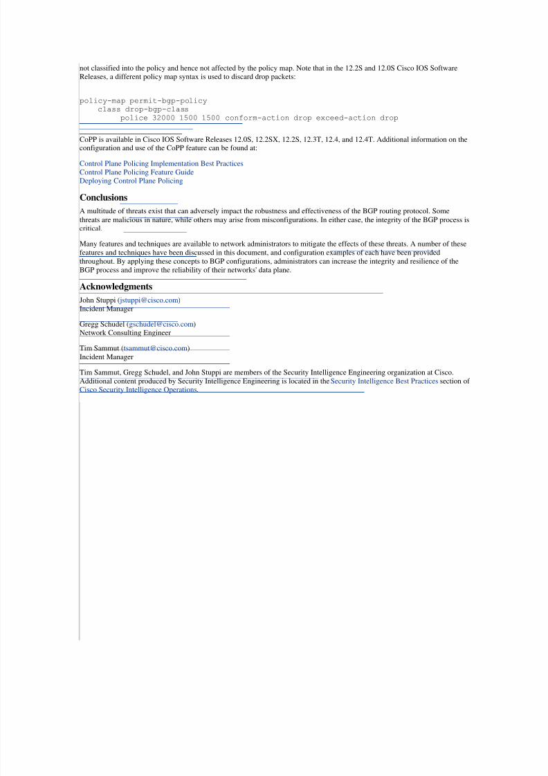
not classified into the policy and hence not affected by the policy map. Note that in the 12.2S and 12.0S Cisco IOS SoftwareReleases, a different policy map syntax is used to discard drop packets:
policy-map permit-bgp-policy
class drop-bgp-class
police 32000 1500 1500 conform-action drop exceed-action drop
CoPP is available in Cisco IOS Software Releases 12.0S, 12.2SX, 12.2S, 12.3T, 12.4, and 12.4T. Additional information on theconfiguration and use of the CoPP feature can be found at:
Control Plane Policing Implementation Best Practices
Control Plane Policing Feature GuideDeploying Control Plane Policing
Conclusions
A multitude of threats exist that can adversely impact the robustness and effectiveness of the BGP routing protocol. Some
threats are malicious in nature, while others may arise from misconfigurations. In either case, the integrity of the BGP process iscritical.
Many features and techniques are available to network administrators to mitigate the effects of these threats. A number of these
features and techniques have been discussed in this document, and configuration examples of each have been provided
throughout. By applying these concepts to BGP configurations, administrators can increase the integrity and resilience of the
BGP process and improve the reliability of their networks' data plane.
Acknowledgments
John Stuppi ( [email protected]) Incident Manager
Gregg Schudel ([email protected]) Network Consulting Engineer
Tim Sammut ([email protected])
Incident Manager
Tim Sammut, Gregg Schudel, and John Stuppi are members of the Security Intelligence Engineering organization at Cisco.
Additional content produced by Security Intelligence Engineering is located in the Security Intelligence Best Practices section of Cisco Security Intelligence Operations.
ReferencesBGP Vulnerability Testing: Separating Fact from FUD v1.1http://www.nanog.org/mtg-0306/pdf/ciag-bgp-v1-1.pdf
RFC 1163
http://www.ietf.org/rfc/rfc1163.txt?number=1163"http://www.ietf.org/rfc/rfc1163.txt?number=1163
RFC 1267http://www.ietf.org/rfc/rfc1267.txt?number=1267
RFC 2385http://tools.ietf.org/html/rfc2385
RFC 1918
http://www.ietf.org/rfc/rfc1918.txt?number=1918
RFC 3330http://www.ietf.org/rfc/rfc3330.txt?number=3330
RFC 2827
http://www.ietf.org/rfc/rfc2827.txt?number=2827
BGP Support for TTL Security Check http://www.cisco.com/en/US/docs/ios/12_3t/12_3t7/feature/guide/gt_btsh.html
Neighbor Router Authenticationhttp://www.cisco.com/en/US/docs/ios/iproute/command/reference/irp_bgp3.html#wp1015208
CIDR Report

7/29/2019 Protecting Border Gateway Protocol for the Enterprise
http://slidepdf.com/reader/full/protecting-border-gateway-protocol-for-the-enterprise 19/19
http://www.cidr-report.org/as2.0/
Configuring the BGP Maximum-Prefix Featurehttp://www.cisco.com/en/US/tech/tk365/technologies_configuration_example09186a008010a28a.shtml
Connecting to a Service Provider Using External BGPhttp://www.cisco.com/en/US/docs/ios/iproute/configuration/guide/irp_bgp_external_sp.html
Protecting Your Core: Infrastructure Protection Access Control Lists
http://www.cisco.com/en/US/tech/tk648/tk361/technologies_white_paper09186a00801a1a55.shtml
Control Plane Policing Implementation Best Practiceshttp://www.cisco.com/web/about/security/intelligence/coppwp_gs.html
Control Plane Policing Feature Guide
http://www.cisco.com/en/US/docs/ios/12_3t/12_3t4/feature/guide/gtrtlimt.html
Deploying Control Plane Policinghttp://www.cisco.com/en/US/products/ps6642/products_white_paper0900aecd804fa16a.shtml
Team Cymru BGP/ASN Analysis Reporthttp://www.cymru.com/BGP/summary.html
bgp maxas-limit
http://www.cisco.com/en/US/docs/ios/12_2/iproute/command/reference/1rfbgp1.html#wp1254976
Parkhurst, William R., Ph.D. "Cisco BGP-4 Command and Configuration Handbook." April 27, 2001
This document is part of Cisco Security Intelligence Operations.
This document is provided on an "as is" basis and does not imply any kind of guarantee or warranty, including the warranties of
merchantability or fitness for a particular use. Your use of the information on the document or materials linked from the
document is at your own risk. Cisco reserves the right to change or update this document at any time.
Back to Top
Cisco Security Intelligence Operations


