
PROFIBUS System
Engineering and
Monitoring
Andy Verwer,
Verwer Training
& Consultancy
Ltd
Accredited PI
Training Centre
PROFINET,
PROFIBUS and IO-
Link Seminar
Siemens
Manchester, 9th
November 2016
PROFIBUS System Engineering & Monitoring, Andy Verwer, page 2Practical Aspects of PROFIBUS, PROFINET and IO-Link, November 2016
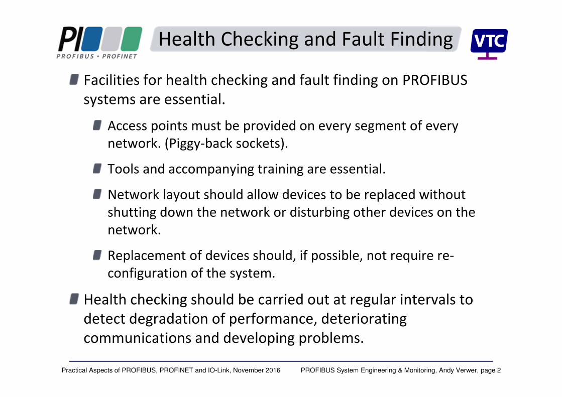
Facilities for health checking and fault finding on PROFIBUS
systems are essential.
Access points must be provided on every segment of every
network. (Piggy-back sockets).
Tools and accompanying training are essential.
Network layout should allow devices to be replaced without
shutting down the network or disturbing other devices on the
network.
Replacement of devices should, if possible, not require re-
configuration of the system.
Health checking should be carried out at regular intervals to
detect degradation of performance, deteriorating
communications and developing problems.
Health Checking and Fault Finding

PROFIBUS System Engineering & Monitoring, Andy Verwer, page 3Practical Aspects of PROFIBUS, PROFINET and IO-Link, November 2016
Permanent Monitoring
Health checking takes time and can only show degradation at the time of the health check.
How much better to integrate the health checking tools into the network?
To give permanent monitoring of system health.
Automatically report failures.
Give pre-warning of impending failures and performance degradation.
A number of tools have appeared on the market which are designed to be permanently connected to the network to provide 24/7 network monitoring.

PROFIBUS System Engineering & Monitoring, Andy Verwer, page 4Practical Aspects of PROFIBUS, PROFINET and IO-Link, November 2016
Permanent monitoring tools
PROCENTEC COMbricks
(Monitors up to four separate networks with 20 DP, Fibre-
Optic or PA segments)
Indu-Sol’s INspektor
network monitor (one DP segment)
Softing’sPROFIBUS Monitor (one DP segment)
PROCENTEC diagnostic hub
(five DP segments)
Siemens diagnostic repeater (three DP segments)
PROFIBUS System Engineering & Monitoring, Andy Verwer, page 5Practical Aspects of PROFIBUS, PROFINET and IO-Link, November 2016
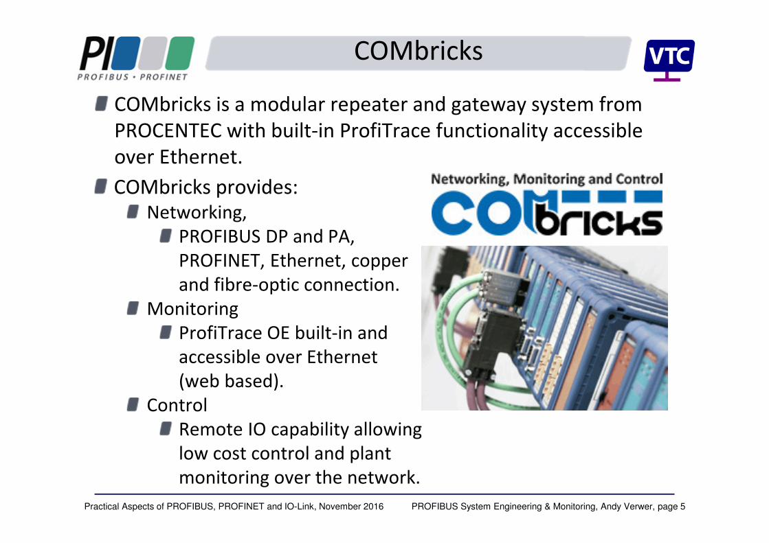
COMbricks
COMbricks is a modular repeater and gateway system from
PROCENTEC with built-in ProfiTrace functionality accessible
over Ethernet.
COMbricks provides:
Networking,
PROFIBUS DP and PA,
PROFINET, Ethernet, copper
and fibre-optic connection.
Monitoring
ProfiTrace OE built-in and
accessible over Ethernet
(web based).
Control
Remote IO capability allowing
low cost control and plant
monitoring over the network.
PROFIBUS System Engineering & Monitoring, Andy Verwer, page 6Practical Aspects of PROFIBUS, PROFINET and IO-Link, November 2016
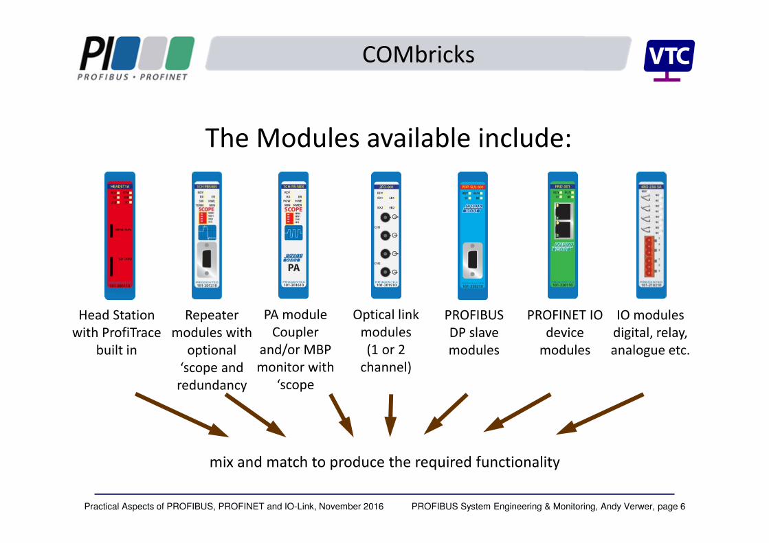
Head Station
with ProfiTrace
built in
Repeater
modules with
optional
‘scope and
redundancy
PROFIBUS
DP slave
modules
IO modules
digital, relay,
analogue etc.
PROFINET IO
device
modules
Optical link
modules
(1 or 2
channel)
mix and match to produce the required functionality
The Modules available include:
PA module
Coupler
and/or MBP
monitor with
‘scope
COMbricks
PROFIBUS System Engineering & Monitoring, Andy Verwer, page 7Practical Aspects of PROFIBUS, PROFINET and IO-Link, November 2016
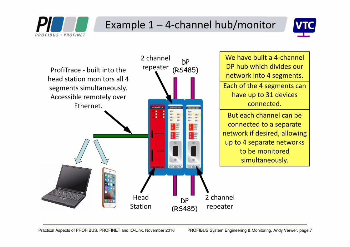
Head
Station
Each of the 4 segments can
have up to 31 devices
connected.
But each channel can be
connected to a separate
network if desired, allowing
up to 4 separate networks
to be monitored
simultaneously.
2 channel
repeater
2 channel
repeater
ProfiTrace - built into the
head station monitors all 4
segments simultaneously.
Accessible remotely over
Ethernet.
Example 1 – 4-channel hub/monitor
We have built a 4-channel
DP hub which divides our
network into 4 segments.
DP (RS485)
DP (RS485)

PROFIBUS System Engineering & Monitoring, Andy Verwer, page 8Practical Aspects of PROFIBUS, PROFINET and IO-Link, November 2016
Example 2 DP/PA coupler/monitor
1 channel
‘scope
repeater
Head
Station
PA coupler
module
This unit can be used as a
stand-alone DP/PA
coupler with both DP and
PA segments monitored
by the head station.
The unit acts like a
transparent link allowing
high-speed DP operation
(up to 1.5Mbit/s)
Ethernet
DP
(RS485)
PA
(MBP)
The same unit can also
simply be configured to
just monitor the signals
on an existing coupler or
link.
These modules incorporate an
oscilloscope function providing
remote waveform visualisation
and bar chart.

PROFIBUS System Engineering & Monitoring, Andy Verwer, page 9Practical Aspects of PROFIBUS, PROFINET and IO-Link, November 2016
Multiple network monitoring
Each COMbricks unit can monitor up to four different
networks, each running at different speeds.
Each network can incorporate DP (RS4845), PA (MBP) or Fibre
Optic (FO) connection via plug-in modules
Up to 20 segments can be connected to a single Head Station.
Multiple COMbricks units can be
incorporated into a factory or
plant.
Centrally located reporting can
be used to provide 24/7
monitoring and health checking.

PROFIBUS System Engineering & Monitoring, Andy Verwer, page 10Practical Aspects of PROFIBUS, PROFINET and IO-Link, November 2016
Engineering Access
Engineering access to the networks and devices is essential
for:
Setting up new/replacement devices;
Configuring equipment;
Accessing device parameters and diagnostics.
Such access can be achieved in a number of ways:
Direct (local) or centralised (remote) access, over the network;
Manufacturer specific interface/software;
Open standardised, vendor-independent methods.
Open methods have the major advantage that the same
software, tools and methods can be used on all supporting
equipment.

PROFIBUS System Engineering & Monitoring, Andy Verwer, page 11Practical Aspects of PROFIBUS, PROFINET and IO-Link, November 2016
OPC
Originally standing for “Object Linking and Embedding for
Process control”, OPC has become the main standard for data
sharing in distributed control and monitoring systems.
OPC is almost universally used for accessing process and
engineering information on automation and control systems.
OPC is actually a set of open standards administered by the
OPC Foundation (www.opcfoundation.org).
OPC servers provide read/write access to data which they hold.
OPC clients can remotely access the data in a vendor
independent way.
There are thousands of different OPC servers and clients
available.

PROFIBUS System Engineering & Monitoring, Andy Verwer, page 12Practical Aspects of PROFIBUS, PROFINET and IO-Link, November 2016
FDT/DTM
Another widely-used standard is the “Field Device Tool” (FDT)
standard.
This defines an open standardised framework for engineering
tools that are used in automation and control systems.
FDT tools are low cost (can be free!) and provide manufacturer
independent access to a wide range of devices.
FDT tools require “Device Type Managers” (DTMs) to access
the data within devices.
There are two different types of DTM provided (usually free):
Communications DTMs (CommDTMs) – establish a
communication route to the devices.
Device DTMs – to access data within a particular type of device.

PROFIBUS System Engineering & Monitoring, Andy Verwer, page 13Practical Aspects of PROFIBUS, PROFINET and IO-Link, November 2016
Simple web browser
07 November
2016
ProfiTrace streaming
FDT/DTM Tools
OPC / SCADA access Alarm handling
Remote monitoring via Ethernet
COMbricks unit
PROFIBUS System Engineering & Monitoring, Andy Verwer, page 14Practical Aspects of PROFIBUS, PROFINET and IO-Link, November 2016
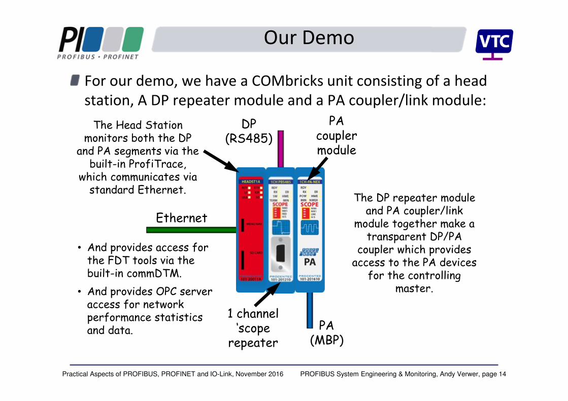
Our Demo
For our demo, we have a COMbricks unit consisting of a head
station, A DP repeater module and a PA coupler/link module:
1 channel ‘scope
repeater
PA coupler module
Ethernet
DP (RS485)
PA (MBP)
The Head Station monitors both the DP
and PA segments via the built-in ProfiTrace,
which communicates via standard Ethernet.
The DP repeater module and PA coupler/link
module together make a transparent DP/PA
coupler which provides access to the PA devices
for the controlling master.
• And provides access for the FDT tools via the built-in commDTM.
• And provides OPC server access for network performance statistics and data.

PROFIBUS System Engineering & Monitoring, Andy Verwer, page 15Practical Aspects of PROFIBUS, PROFINET and IO-Link, November 2016
FDT/DTM
• The FDT provides a standardised framework in
which the required DTMs can be loaded and run.
• The device DTMs operate underneath the
CommDTM in order to provide a route to the
devices.
CommDTM
Device DTMs
DP
PA
COMbricks
transparent
coupler and
Ethernet
gateway
Devices
Eth
ern
et


