
58STA/STX4-WAY MULTIPOISE INDUCED-COMBUSTIONGAS FURNACEInput Capacities: 45,000 thru 155,000 Btuh
Product Data
A04039
THE CARRIER 58STA/STX GAS FURNACEThe 58STA/STX 4--way Multipoise Gas Furnaces feature Carrier’sQuieTecht noise reduction system for incredibly quiet induceddraft operation. Applications are easy with 4--way multipoisedesign, through-the-furnace downflow venting, 13 differentventing options, and a door designed for easy service access. Aninner blower door is provided for tighter sealing in sensitiveapplications. The 58STA/STX furnaces are approved for use withnatural or propane gas, and the 58STX is approved for use in LowNOx Air Management Districts.
STANDARD FEATURES— QuieTecht noise reduction system
— Microprocessor based control centerLED diagnostics and self test featureAdjustable heating air temperatureriseAdjustable cooling airflow
— 4--way Multipoise furnace, 13 vent applications
— Compact design -- only 33--1/3 in. (847 mm) tall
— Power Heatt Igniter
— Draft safeguard switch to ensure proper furnaceventing
— Inner door for tighter sealing
— HYBRID HEATr Dual Fuel System compatible
— All models are chimney friendly when used withaccessory vent kit
— Twinning in Upflow, Downflow and Horizontal
— Residential installations eligible for consumerfinancing through the Retail Credit Program

2
A02169
HEAT EXCHANGERA02015
CONTROL BOARD
A02170
INDUCER BLOWER
MODEL NUMBER NOMENCLATURE
58STA 045 100 08
58STA 4--Way Multipoise Nominal Cooling Size58STX Low NOx version (Airflow at .5 e.s.p.)
(400 CFM per 12,000 Btuh)08---800 CFM12---1200 CFM14---1400 CFM16---1600 CFM
Input Capacity 20---2000 CFM045---44,000 Btuh 110---110,000 Btuh 22---2200 CFM070---66,000 Btuh 135---132,000 Btuh090---88,000 Btuh 155---154,000 Btuh Series Number
58STA/STX

3
FURNACE COMPONENTS
INDUCER MOROR ASSEMBLY
PRESSURE SWITCHES
FLUE COLLECTOR
BOX
GAS VALVE
HOT SURFACE IGNITER
MANUAL RESET LIMIT SWITCHES
CONTROL
VENT ELBOW*
MAIN LIMIT SWITCH(BEHIND
DRAFT SAFEGUARD SWITHCH
BLOWER AND MOTOR
RATING PLATE NOT SHOWN
(LOCATED ON BLOWER DOOR)
GAS MANIFOLD
GAS BURNER
BLOWER DOOR SAFETY SWITCH
FLAME SENSOR
*Elbow may be turned to a different
position, depending on type of installation.
A04138
NOTE: The 58STA/STX Furnaces are factory shipped for use with natural gas. These furnaces can be field-converted for propane gas witha factory-authorized and listed accessory conversion kit.
58STA/STX

4
CARRIER ACCESSORIES
CONTROLS:THERMOSTATSAND ZONING
Available in programmable andnon-programmable models,Carrier thermostats maintain aconstant temperature level in thehome.
For the ultimate in homecomfort, Carrier’s 2, 4, and8-zone systems allowtemperature control ofindividual “zones” of the home.This is accomplished through aseries of electronic dampers andremote room sensors. The4-zone system is shown.
A97432
MECHANICALOR ELECTRONICAIR CLEANER
Cleans the air of smoke, dirt,and many pollens commonlyfound. Saves decorating andcleaning expenses by keepingcarpets, furniture, and drapescleaner.
Electronic air cleaner isshown.
A04008
A01484
MODEL HUMCCLFPHUMIDIFIER
By adding moisture to winter-dryair, a Carrier humidifier can oftenimprove comfort and keepfurniture, rugs, and draperies inbetter condition. Moisturizinghousehold air also helps to retainnormal body heat and providescomfort at lower temperatures.
A02121EXTERNAL FILTER
RACK(SIDE OR BOTTOM)Custom--made filter rack foreasy connection when areturn plenum already exists.Provides easy access forcleaning filter.
Accessories
ELECTRONIC AIR CLEANER (EAC) Model EACB
MECHANICAL AIR CLEANER Models EZXCAB, FILCAB
HUMIDIFIER Model HUM
HEAT RECOVERY VENTILATOR Model HRV
ENERGY RECOVERY VENTILATOR Model ERV
UV LIGHTS Model UVL
THERMOSTAT ---NON-PROGRAMMABLE
For use with 1-speed Air Conditioner --- deg. F/C, Auto Changeover --- TP---NAC, TC---NAC
For use with 1-speed Heat Pump --- deg. F/C, Auto Changeover --- TP---NHP, TC---NHP*
For use with 2-speed Air Conditioner --- deg. F/C, Auto Changeover --- TP---NRH*
For use with multi-use / stage configurations --- deg. F/C, Auto Changeover/Temperature and HumidityControl --- TP---PRH{
THERMOSTAT ---PROGRAMMABLE
For use with 1-speed Air Conditioner --- deg. F/C, Auto Changeover, 7-Day Programmable ---TP---PAC
For use with 1-speed Heat Pump --- deg. F/C, Auto Changeover, 7-Day Programmable ---TP---PHP*
For use with 2-speed Air Conditioner --- deg. F/C, Auto Changeover, 7-Day Programmable ---TP---PRH*
For use with 1-speed Air Conditioner --- deg. F/C, 5---2 Day Programmable --- TP---PAC
For use with multi-stage applications --- deg. F/C, Auto Changeover, 7-Day Programmable --- TC---PHP}
For multi-use / stage configurations --- deg. F/C, Auto Changeover, 7-Day Programmable/Temperature andHumidity Control ---TP---PRH{
ZONING CONTROL
Comfort™ Series 3-Zone Kit --- ZONECC3ZAC01, ZONECC3ZHP01
2 Performance™ Series ComfortZone™ II Zoning/Temperature and Humidity Control --- ZONECC2KIT01---B
4 Performance™ Series ComfortZone™ II Zoning/Temperature and Humidity Control --- ZONECC4KIT01---B
8 Performance™ Series ComfortZone™ II Zoning/Temperature and Humidity Control --- ZONECC8KIT01---B
* Model HP and 2S thermostat must be field converted to air conditioner operation.† Thermidistat Control can be configured for multiple use and staging, it must be configured for each specific application.
} Dual Fuel thermostat is used with furnace and heat pump application.
58STA/STX

5
CARRIER ACCESSORIES
DESCRIPTION58STA/STX
PART NO. 045-08
045-12
070-08
070-12
070-16
090-14
090-16
090-20
110-12
110-16
110-22
135-16
135-22
155-20
Performance Series Filter Cabinet
FILCABCC0016 X X X X X X X
FILCABCC0020 X X X X X
FILCABCC0024 X X
Cartridge Media Filter
FILCCCAR0016 X X X X X X X
FILCCCAR0020 X X X X X
FILCCCAR0024 X X
EZ Flex Media Filter with End Caps
EXPXXUNV0016 X X X X X X X
EXPXXUNV0020 X X X X X
EXPXXUNV0024 X X
Replacement EZ Flex Filter Media
EXPXXFIL0016 X X X X X X X
EXPXXFIL0020 X X X X X
EXPXXFIL0024 X X
External Bottom Return Filter Rack
KGAFR0401B14 X X X X
KGAFR0501B17 X X X
KGAFR0601B21 X X X X X
KGAFR0701B24 X X
External Side Return Filter Rack KGAFR0801SRE X X X X X X X X X X X X X X
Unframed Filter 3/4-in. (19 mm)
KGAWF1301UFR† X X X X X X X
KGAWF1401UFR X X X X X
KGAWF1501UFR X X
KGAWF1306UFR† X X X X X X X
KGAWF1406UFR X X X X X
KGAWF1506UFR X X
Flue Extension KGAFE0112UPH X X X X X X X X X X X X X X
Twinning Kit KGATW0601HSI X X X X X X X X X X X X X X
Combustible Floor Base KGASB0201ALL X X X X X X X X X X X X X X
Downflow Vent Guard KGAVG0101DFG X X X X X X X X X X X X X X
Vent Extension Kit KGAVE0101DNH X X X X X X X X X X X X X X
Chimney Adapter KitKGACA02014FC X X X X X X X X X X X
KGACA02015FC X X X
Natural-to-Propane Conversion Kit* KGANP4601ALL X X X X X X X X X X X X X X
Propane-to-Natural Conversion Kit KGAPN3901ALL X X X X X X X X X X X X X X
Label Kit KGALB0101KIT X X X X X X X X X X X X X X
Air Leakage Kit (Qty 10) KGBAC0110DGK X X X X X X X X X X X X X X
Gas Orifice Kit (Qty 50)
KGAHA0150N42
See Installation Instructions for model,altitude, and heat value usages.
KGAHA0250N43(factory supplied)
KGAHA0350N44
KGAHA0450N45
KGAHA0550N46
KGAHA1550N47
KGAHA1650N48
KGAHA0650P54
KGAHA0750P55
KGAHA5750125
KGAHA5750130
KGAHA0850P56
* Factory-authorized and field installed. Fuel conversion kits are AGA/CGA recognized.† Suitable for Side Return Filter Rack (KGAFR0801SRE)
X = Accessory
S = Standard
58STA/STX

6
PHYSICAL DATA
UNIT SIZE
045 070 090
08 12 08 12 16 14 16
OUTPUT CAPACITY BTUH*(Nonweatherized ICS) †
58STX Upflow; all 58STA 35,000 36,000 53,000 54,000 53,000 71,000 71,000
58STX Downflow/Horizontal 34,000 34,000 51,000 51,000 51,000 68,000 68,000
INPUT BTUH*58STX Upflow; all 58STA 44,000 44,000 66,000 66,000 66,000 88,000 88,000
58STX Downflow/Horizontal 42,000 42,000 63,000 63,000 63,000 84,000 84,000
AFUE%* Nonweatherized ICS 80.0 80.0 80.0 80.0 80.0 80.0 80.0
SHIPPING WEIGHT --- LB (KG) 104 (47) 107 (49) 111 (50) 115 (52) 126 (57) 127 (58) 140 (64)
CERTIFIED TEMP RISE RANGE ° F (° C) 30---60(17---33)
20---50(11---28)
40---70(22---39)
30---60(17---33)
25---55(14---30)
40---70(22---39)
30---60(17---33)
CERTIFIED EXTSTATIC PRESSURE
Heating 0.10 0.10 0.12 0.12 0.12 0.15 0.15
Cooling 0.50 0.50 0.50 0.50 0.50 0.50 0.50
AIRFLOW CFM‡Heating 920 1250 720 1195 1450 1375 1505
Cooling 845 1160 900 1200 1530 1385 1720
LIMIT CONTROL SPST
HEATING BLOWER CONTROL Solid-State Time Operation
BURNERS (Monoport) 2 2 3 3 3 4 4
GAS CONNECTION SIZE 1/2---in. NPT
GAS VALVE (Redundant) Manufacturer White-Rodgers
Minimum Inlet Pressure (In. wc) 4.5 (Natural Gas)
Maximum Inlet Pressure (In. wc) 13.6 (Natural Gas)
IGNITION DEVICE Hot Surface
* Gas input ratings are certified for elevations to 2000 ft. (610 M). In USA, for elevations above 2000 ft. (605 M), reduce ratings 4 percent for each 1000 ft.(305 M) above sea level. In Canada, derate the unit 10 percent for elevations 2000 to 4500 ft (610 to 1372 M) above sea level. Refer to National Fuel GasCode NFPA 54/ANSI Z223.1---2006 Table F.1 (d) or furnace Installation Instructions.
† Capacity in accordance with U.S. Government DOE test procedures.
‡ Airflow shown is for bottom only return ---air supply. For air delivery above 1800 CFM, see Air Delivery Table for other options. A filter is required for eachreturn-air supply.
ICS — Isolated Combustion System
BLOWER PERFORMANCE DATA
UNIT SIZE
045 070 090
08 12 08 12 16 14 16
DIRECT---DRIVE MOTOR Hp (PSC) 1/5 1/3 1/5 1/3 1/2 1/3 1/2
MOTOR FULL LOAD AMPS 2.9 5.2 2.9 5.2 7.9 5.2 7.9
RPM (Nominal) 1075---3 1075---3 1075---3 1075---3 1075---3 1075---3 1075---3
BLOWER WHEEL DIAMETER X WIDTHS --- IN. (mm) 10 x 6(254 x 152)
10 x 6(254 x 152)
10 x 6(254 x 152)
10 x 6(254 x 152)
11 x 8(279 x 203)
10 x 8(254 x 203)
10 x 10(254 x 254)
ECM---Electronically Commutated Motor, Variable Speed
58STA/STX
7
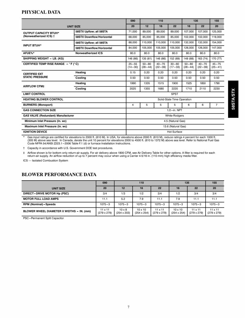
PHYSICAL DATA
UNIT SIZE
090 110 135 155
20 12 16 22 16 22 20
OUTPUT CAPACITY BTUH*(Nonweatherized ICS) †
58STX Upflow; all 58STA 71,000 89,000 89,000 89,000 107,000 107,000 125,000
58STX Downflow/Horizontal 68,000 85,000 85,000 85,000 102,000 102,000 119,000
INPUT BTUH*58STX Upflow; all 58STA 88,000 110,000 110,000 110,000 132,000 132,000 154,000
58STX Downflow/Horizontal 84,000 105,000 105,000 105,000 126,000 126,000 147,000
AFUE%* Nonweatherized ICS 80.0 80.0 80.0 80.0 80.0 80.0 80.0
SHIPPING WEIGHT --- LB. (KG) 146 (66) 135 (61) 146 (66) 152 (69) 149 (68) 163 (74) 170 (77)
CERTIFIED TEMP RISE RANGE --- ° F (° C) 25---55(14---30)
50---80(28---44)
40---70(22---39)
30---60(17---33)
50---80(28---44)
40---70(22---39)
45---75(25---41)
CERTIFIED EXTSTATIC PRESSURE
Heating 0.15 0.20 0.20 0.20 0.20 0.20 0.20
Cooling 0.50 0.50 0.50 0.50 0.50 0.50 0.50
AIRFLOW CFM‡Heating 1990 1335 1515 1900 1525 1850 1790
Cooling 2025 1355 1680 2220 1710 2110 2230
LIMIT CONTROL SPST
HEATING BLOWER CONTROL Solid-State Time Operation
BURNERS (Monoport) 4 5 5 5 6 6 7
GAS CONNECTION SIZE 1/2---in. NPT
GAS VALVE (Redundant) Manufacturer White-Rodgers
Minimum Inlet Pressure (In. wc) 4.5 (Natural Gas)
Maximum Inlet Pressure (In. wc) 13.6 (Natural Gas)
IGNITION DEVICE Hot Surface
* Gas input ratings are certified for elevations to 2000 ft. (610 M). In USA, for elevations above 2000 ft. (610 M), reduce ratings 4 percent for each 1000 ft.(305 M) above sea level. In Canada, derate the unit 10 percent for elevations 2000 to 4500 ft. (610 to 1372 M) above sea level. Refer to National Fuel GasCode NFPA 54/ANSI Z223.1---2006 Table F.1 (d) or furnace Installation Instructions.
† Capacity in accordance with U.S. Government DOE test procedures.
‡ Airflow shown is for bottom only return-air supply. For air delivery above 1800 CFM, see Air Delivery Table for other options. A filter is required for eachreturn-air supply. An airflow reduction of up to 7 percent may occur when using a Carrier 4-5/16 in. (110 mm) high efficiency media filter.
ICS — Isolated Combustion System
BLOWER PERFORMANCE DATA
UNIT SIZE
090 110 135 155
20 12 16 22 16 22 20
DIRECT---DRIVE MOTOR Hp (PSC) 3/4 1/3 1/2 3/4 1/2 3/4 3/4
MOTOR FULL LOAD AMPS 11.1 5.2 7.9 11.1 7.9 11.1 11.1
RPM (Nominal) ---Speeds 1075---3 1075---3 1075---3 1075---3 1075---3 1075---3 1075---3
BLOWER WHEEL DIAMETER X WIDTHS --- IN. (mm) 11 x 11(279 x 279)
10 x 8(254 x 203)
10 x 10(254 x 254)
11 x 11(279 x 279)
10 x 10(254 x 254)
11 x 11(279 x 279)
11 x 11(279 x 279)
PSC---Permanent Split Capacitor
58STA/STX
8
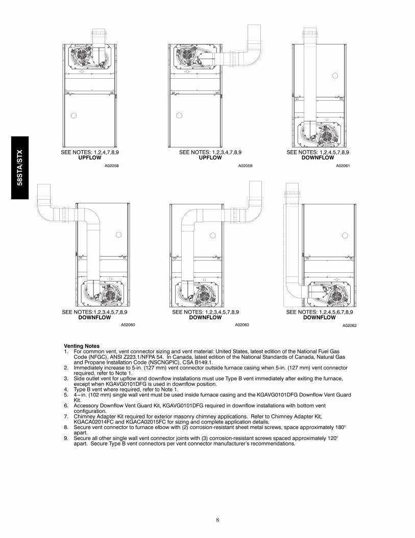
A02058
SEE NOTES: 1,2,4,7,8,9UPFLOW
SEE NOTES: 1,2,3,4,7,8,9UPFLOW
SEE NOTES: 1,2,4,5,7,8,9DOWNFLOW
A02059 A02061
SEE NOTES:1,2,3,4,5,7,8,9DOWNFLOW
SEE NOTES: 1,2,3,4,5,7,8,9DOWNFLOW
SEE NOTES: 1,2,4,5,6,7,8,9DOWNFLOW
A02060 A02063 A02062
Venting Notes1. For common vent, vent connector sizing and vent material: United States, latest edition of the National Fuel GasCode (NFGC), ANSI Z223.1/NFPA 54. In Canada, latest edition of the National Standards of Canada, Natural Gasand Propane Installation Code (NSCNGPIC), CSA B149.1.
2. Immediately increase to 5-in. (127 mm) vent connector outside furnace casing when 5-in. (127 mm) vent connectorrequired, refer to Note 1.
3. Side outlet vent for upflow and downflow installations must use Type B vent immediately after exiting the furnace,except when KGAVG0101DFG is used in downflow position.
4. Type B vent where required, refer to Note 1.5. 4--- in. (102 mm) single wall vent must be used inside furnace casing and the KGAVG0101DFG Downflow Vent GuardKit.
6. Accessory Downflow Vent Guard Kit, KGAVG0101DFG required in downflow installations with bottom ventconfiguration.
7. Chimney Adapter Kit required for exterior masonry chimney applications. Refer to Chimney Adapter Kit,KGACA02014FC and KGACA02015FC for sizing and complete application details.
8. Secure vent connector to furnace elbow with (2) corrosion-resistant sheet metal screws, space approximately 180°apart.
9. Secure all other single wall vent connector joints with (3) corrosion-resistant screws spaced approximately 120°apart. Secure Type B vent connectors per vent connector manufacturer’s recommendations.
58STA/STX
9
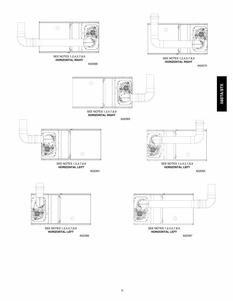
HORIZONTAL RIGHTSEE NOTES 1,2,4,5,7,8,9
A02068
HORIZONTAL RIGHTSEE NOTES 1,2,4,7,8,9
A02069
HORIZONTAL RIGHTSEE NOTES 1,2,4,5,7,8,9
A02070
HORIZONTAL LEFTSEE NOTES 1,2,4,7,8,9
A02064HORIZONTAL LEFT
SEE NOTES 1,2,4,5,7,8,9
A02065
HORIZONTAL LEFTSEE NOTES 1,2,4,5,7,8,9
A02066HORIZONTAL LEFT
SEE NOTES 1,2,4,5,7,8,9
A02067
58STA/STX
10
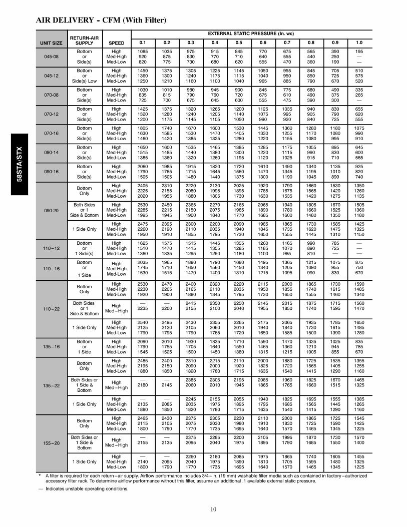
AIR DELIVERY -- CFM (With Filter)
UNIT SIZERETURN-AIRSUPPLY SPEED
EXTERNAL STATIC PRESSURE (In. wc)
0.1 0.2 0.3 0.4 0.5 0.6 0.7 0.8 0.9 1.0
045-08Bottomor
Side(s)
HighMed-HighMed-Low
1085920820
1035875775
975830730
915770680
845710620
770640555
675555470
565440360
390250190
195——
045-12Bottomor
Side(s) Low
HighMed-HighMed-Low
145013601250
137513001210
130512401160
122511751100
114511151040
10501040965
955950885
845850790
705725670
510575520
070-08Bottomor
Side(s)
HighMed-HighMed-Low
1030835725
1010815700
980790675
945760645
900720600
845675555
775610475
680490390
490375300
335265—
070-12Bottomor
Side(s)
HighMed-HighMed-Low
142513201200
137512801175
132012401145
126512051105
120011401050
11251075990
1035995920
940905840
830790725
655620555
070-16Bottomor
Side(s)
HighMed-HighMed-Low
180516301460
174015851420
167015301385
160014701325
153014051280
144513301220
136012551155
128011701080
11801080995
1075990910
090-14Bottomor
Side(s)
HighMed-HighMed-Low
165015151385
160014851360
153514401320
146513801260
138513001195
128512201120
117511151025
1055990915
895830710
645600565
090-16Bottomor
Side(s)
HighMed-HighMed-Low
206017901505
198517651505
191517151480
182016451440
172015601375
161014701300
149013451190
134011951045
11351010890
925820740
090-20
BottomOnly
HighMed-HighMed-Low
240522252020
231021551955
222020801880
213019951805
202518951730
192017851630
179016751535
166015651420
153014201275
135012601135
Both Sidesor 1
Side & Bottom
HighMed-HighMed-Low
253022851995
245022151945
236521501900
227020751840
216519851770
206518901685
194017801600
180516601480
167015251350
150513601180
1 Side OnlyHigh
Med-HighMed-Low
247522601950
239521901910
230021101855
220020351795
209019401730
198518451650
186517351555
173016201445
158514751310
142513251150
110---12Bottomor
1 Side(s)
HighMed-HighMed-Low
162515101360
157514701335
151514151295
144513551250
135512851180
126011851100
11651070985
990890810
785725⎯
⎯⎯⎯
110---16Bottomor
1 Side
HighMed-HighMed-Low
203517451530
196517101515
188016501470
179015601400
168014501310
149513401215
136512051095
12151090990
1075955830
875750670
110---22
BottomOnly
HighMed-HighMed-Low
253022301920
247022051900
240021651880
232021101845
222020351795
211519501730
200018551650
186517401555
173016151460
159014851340
Both Sidesor 1
Side & Bottom
HighMed---High
⎯2235
⎯2200
24152155
23502100
22502040
21451955
20151850
18751740
17151595
15601470
1 Side OnlyHigh
Med-HighMed-Low
254021251790
249521201795
243021051790
235520601765
226520101720
217519401650
206518401585
193517301500
178516151390
165014851280
135---16Bottomor1 Side
HighMed-HighMed-Low
209017901545
201017551525
193017051500
183516401450
171015501380
159014651315
147013601215
133512101005
1025945855
835785670
135---22
BottomOnly
HighMed-HighMed-Low
248521951880
240021501850
231020901820
221520001780
211019201715
200018251635
188017201540
172515651415
153514051290
135512551160
Both Sides or1 Side &Bottom
HighMed---High
⎯2180
⎯2145
23852060
23052010
21951945
20851865
19601765
18251660
16701515
14651325
1 Side OnlyHigh
Med-HighMed-Low
⎯21351880
⎯20851850
224520351820
215519751780
205518951715
194017951635
182516851540
169515651415
155514451290
138512651160
155---20
BottomOnly
HighMed-HighMed-Low
246521151800
243021051790
237520751770
230520301735
223019801695
211019101640
200018301570
186517251465
172515901345
154514251225
Both Sides or1 Side &Bottom
HighMed---High
⎯2155
⎯2135
23752095
22852040
22001975
21051895
19951790
18701685
17301550
15701400
1 Side OnlyHigh
Med-HighMed-Low
⎯21401800
⎯20951790
226020401770
218019751735
208518901695
197518101640
186517051570
174015951465
160514801345
145513251225
* A filter is required for each return ---air supply. Airflow performance includes 3/4---in. (19 mm) washable filter media such as contained in factory---authorizedaccessory filter rack. To determine airflow performance without this filter, assume an additional .1 available external static pressure.
— Indicates unstable operating conditions.
58STA/STX
11
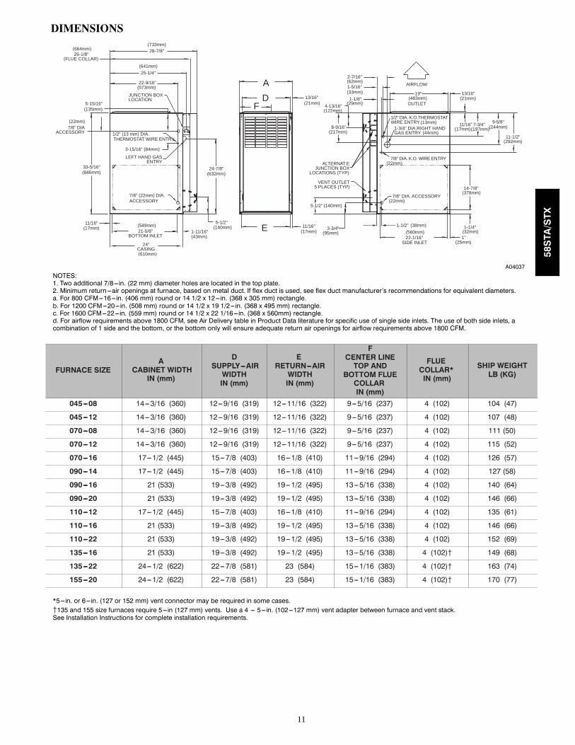
DIMENSIONS
2-7/16"
1-1/8"
28-7/8" (733mm)
25-1/4"
22-9/16"
JUNCTION BOX LOCATION
7/8" DI A ACCESSORY 1/2" (13 mm) DIA.
THERMOSTAT WIRE ENTRY
3-15/16" (84mm)
LEFT HAND GAS ENTRY
33-5/16" 24-7/8"
5-1/2"
7/8" (22mm) DIA.ACCESSORY
11/16"
21-5/8" BOTTOM INLE T
1-11/16"
13/16"
11/16"
4-13/16"
AIRFLOW
19"
OUTLE T
13/16"
11/16" 8-9/16"
VENT OUTLE T 5 PLACES (TYP)
3-3/4"
1-3/4" DIA.RIGHT HAND GAS ENTRY
7/8" DIA. K.O. WIRE ENTRY
SIDE INLE T
14-7/8"
7/8" DIA. ACCESSORY
1-1/4"
1" 22-1/16"
A D
F
E
(FLUE COLLAR)
5-15/16"(135mm)
24" CASING
1-5/16"
1/2" DIA. K.O.THERMOSTAT WIRE ENTRY
ALTERNAT E JUNCTION BOX
LOCATIONS (TYP)
26-1/8"
1-1/2"
7-3/4" 9-5/8"
11-1/2"
5-1/2"
(664mm)
(641mm)
(573mm)
(22mm)
(846mm)
(17mm) (549mm)
(610mm)
(43mm)
(140mm)
(632mm)
(17mm)
(140mm)
(95mm)
(21mm) (122mm)
(217mm)
(62mm)
(33mm)
(29mm) (483mm)
(13mm)
(44mm)
(22mm)
(22mm)
(38mm) (560mm)
(25mm)
(32mm)
(378mm)
(17mm) (197mm) (244mm)
(292mm)
(21mm)
A04037
NOTES:1. Two additional 7/8---in. (22 mm) diameter holes are located in the top plate.2. Minimum return ---air openings at furnace, based on metal duct. If flex duct is used, see flex duct manufacturer’s recommendations for equivalent diameters.a. For 800 CFM---16---in. (406 mm) round or 14 1/2 x 12---in. (368 x 305 mm) rectangle.b. For 1200 CFM---20---in. (508 mm) round or 14 1/2 x 19 1/2---in. (368 x 495 mm) rectangle.c. For 1600 CFM---22---in. (559 mm) round or 14 1/2 x 22 1/16---in. (368 x 560mm) rectangle.d. For airflow requirements above 1800 CFM, see Air Delivery table in Product Data literature for specific use of single side inlets. The use of both side inlets, acombination of 1 side and the bottom, or the bottom only will ensure adequate return air openings for airflow requirements above 1800 CFM.
FURNACE SIZEA
CABINET WIDTHIN (mm)
DSUPPLY---AIRWIDTHIN (mm)
ERETURN---AIRWIDTHIN (mm)
FCENTER LINETOP AND
BOTTOM FLUECOLLARIN (mm)
FLUECOLLAR*IN (mm)
SHIP WEIGHTLB (KG)
045---08 14---3/16 (360) 12---9/16 (319) 12---11/16 (322) 9---5/16 (237) 4 (102) 104 (47)
045---12 14---3/16 (360) 12---9/16 (319) 12---11/16 (322) 9---5/16 (237) 4 (102) 107 (48)
070---08 14---3/16 (360) 12---9/16 (319) 12---11/16 (322) 9---5/16 (237) 4 (102) 111 (50)
070---12 14---3/16 (360) 12---9/16 (319) 12---11/16 (322) 9---5/16 (237) 4 (102) 115 (52)
070---16 17---1/2 (445) 15---7/8 (403) 16---1/8 (410) 11---9/16 (294) 4 (102) 126 (57)
090---14 17---1/2 (445) 15---7/8 (403) 16---1/8 (410) 11---9/16 (294) 4 (102) 127 (58)
090---16 21 (533) 19---3/8 (492) 19---1/2 (495) 13---5/16 (338) 4 (102) 140 (64)
090---20 21 (533) 19---3/8 (492) 19---1/2 (495) 13---5/16 (338) 4 (102) 146 (66)
110---12 17---1/2 (445) 15---7/8 (403) 16---1/8 (410) 11---9/16 (294) 4 (102) 135 (61)
110---16 21 (533) 19---3/8 (492) 19---1/2 (495) 13---5/16 (338) 4 (102) 146 (66)
110---22 21 (533) 19---3/8 (492) 19---1/2 (495) 13---5/16 (338) 4 (102) 152 (69)
135---16 21 (533) 19---3/8 (492) 19---1/2 (495) 13---5/16 (338) 4 (102){ 149 (68)
135---22 24---1/2 (622) 22---7/8 (581) 23 (584) 15---1/16 (383) 4 (102){ 163 (74)
155---20 24---1/2 (622) 22---7/8 (581) 23 (584) 15---1/16 (383) 4 (102){ 170 (77)
*5---in. or 6---in. (127 or 152 mm) vent connector may be required in some cases.{135 and 155 size furnaces require 5---in (127 mm) vents. Use a 4 --- 5---in. (102---127 mm) vent adapter between furnace and vent stack.See Installation Instructions for complete installation requirements.
58STA/STX

12
A08471
EFFICIENCYRATINGCERTIFIED
MEETS DOE RESIDENTIAL CONSERVATIONSERVICES PROGRAM STANDARDS.
Before purchasing this appliance, read importantenergy cost and efficiency information availablefrom your retailer.
58STA/STX
13
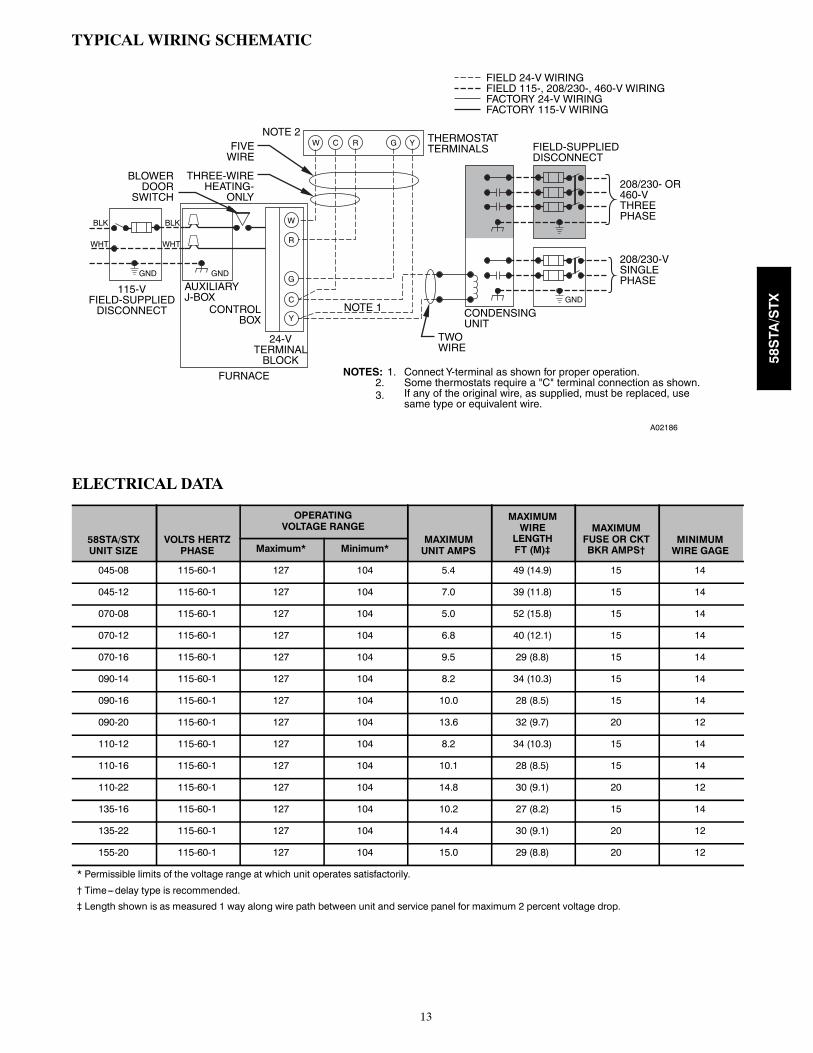
TYPICAL WIRING SCHEMATIC
A02186
ELECTRICAL DATA
58STA/STXUNIT SIZE
VOLTS HERTZPHASE
OPERATINGVOLTAGE RANGE
MAXIMUMUNIT AMPS
MAXIMUMWIRELENGTHFT (M)‡
MAXIMUMFUSE OR CKTBKR AMPS†
MINIMUMWIRE GAGEMaximum* Minimum*
045-08 115-60-1 127 104 5.4 49 (14.9) 15 14
045-12 115-60-1 127 104 7.0 39 (11.8) 15 14
070-08 115-60-1 127 104 5.0 52 (15.8) 15 14
070-12 115-60-1 127 104 6.8 40 (12.1) 15 14
070-16 115-60-1 127 104 9.5 29 (8.8) 15 14
090-14 115-60-1 127 104 8.2 34 (10.3) 15 14
090-16 115-60-1 127 104 10.0 28 (8.5) 15 14
090-20 115-60-1 127 104 13.6 32 (9.7) 20 12
110-12 115-60-1 127 104 8.2 34 (10.3) 15 14
110-16 115-60-1 127 104 10.1 28 (8.5) 15 14
110-22 115-60-1 127 104 14.8 30 (9.1) 20 12
135-16 115-60-1 127 104 10.2 27 (8.2) 15 14
135-22 115-60-1 127 104 14.4 30 (9.1) 20 12
155-20 115-60-1 127 104 15.0 29 (8.8) 20 12
* Permissible limits of the voltage range at which unit operates satisfactorily.
† Time---delay type is recommended.
‡ Length shown is as measured 1 way along wire path between unit and service panel for maximum 2 percent voltage drop.
58STA/STX

14
TYPICAL INSTALLATION
CONDENSINGUNIT
AIRFLOW
ELECTRONICAIR CLEANER
GAS-FIREDWATER HEATER
HUMIDIFIER
A02184
58STA/STX

15
58STA/STX

16
GUIDE SPECIFICATIONSGas Furnace58STA/STXGeneralSYSTEM DESCRIPTIONFurnish a _________________ fixed capacity gas--fired
furnace for use with natural gas or propane (factoryauthorized conversion kit required for propane); furnishcold air return plenum; furnish external medial cabinet foruse with accessory media filter or standard filter.QUALITY ASSURANCEUnit will be designed, tested and constructed to the
current ANSI Z 21.47/CSA 2.3 design standard forgas--fired central furnaces.Unit will be 3rd party certified by CSA to the current
ANSI Z 21.47/CSA 2.3 design standard for gas--firedcentral furnaces.Unit will carry the CSA Blue StarR and Blue FlameR
labels.Unit efficiency testing will be performed per the current
DOE test procedure as listed in the Federal Register.Unit will be certified for capacity and efficiency and
listed in the latest GAMA Consumer’s Directory ofCertified Efficiency Ratings.Unit shall carry the current Federal Trade Commission
Energy Guide efficiency label.DELIVERY, STORAGE AND HANDLINGUnit shall be shipped as single package only and is
stored and handled per unit manufacturer’srecommendations.WARRANTY (for inclusion by specifying engineer)U.S. and Canada only. Warranty certificate available
upon request.ProductsEQUIPMENTComponents shall include: slow--opening gas valve to
reduce ignition noise, regulate gas flow, with electricswitch gas shut--off; flame proving sensor, hot surfaceigniter, pressure switch assembly, flame rollout switch,blower and inducer assembly, 40va transformer;low--voltage (heating) (heating/cooling) thermostat.Blower Wheel and Blower Motor
Galvanized blower wheel shall be centrifugal type,statically and dynamically balanced. Blower motor of PSCtype shall be permanently lubricated with sealed bearings,of _______hp, and shall be multiple--speed direct drive.Blower motor shall be soft mounted to the blower scroll toreduce vibration transmission.FiltersFurnace may have reusable--type filters. Filter shall be
_______ in. (mm) (x) _______in. (mm). An accessory
high efficiency Media Filter is available as an option._______________ Media Filter.CasingCasing shall be of .030 in. (.76) thickness minimum,
pre--painted galvanized steel.Inducer Motor
Inducer motor shall be soft mounted to reduce vibrationtransmission.Draft Safeguard Switch
Draft Safeguard Switch (blocked vent safeguard) shallbe factory installed to reduce the possibility of vent gasinfiltration due to a blocked or restricted vent pipe.Heat Exchangers
Heat exchangers shall be a 4-Pass 20 gage aluminizedsteel of fold--and--crimp sectional design when appliedoperating under negative pressure.ControlsControl shall include a micro--processor based
integrated electronic control board with at least 11 servicetroubleshooting codes displayed via diagnostic flashingLED light on the control, a self--test feature that checks allmajor functions of the furnace within one minute, and areplaceable automotive--type circuit protection fuse.Multiple operational settings available including, separateblower speeds for heating, cooling and continuous fan.Continuous fan speed may be adjusted from thethermostat. Cooling airflow will be selectable between 350or 400 CFM per ton of air conditioning.OPERATING CHARACTERISTICSHeating Capacity shall be ________ Btuh input;
________ Btuh output capacity.Fuel Gas Efficiency shall be 80% AFUE. Air delivery
shall be ___________ cfm minimum at 0.50 in. wcexternal static pressure.Dimensions shall be: depth __________ in. (mm);
width _________ in. (mm); height_________in. (mm)(casing only). Height shall be_________in. (mm) withA/C coil and _____________in. (mm) overall withplenum.ELECTRICAL REQUIREMENTSElectrical supply shall be 115 volts, 60 Hz,
single--phase (nominal). Minimum wire size shallbe_________AWG; maximum fuse size or circuit breakershall be __________Amps.SPECIAL FEATURESRefer to section of the product data sheet identifying
accessories and descriptions for specific features andavailable enhancements.
Copyright 2009 Carrier Corp. D 7310 W. Morris St. D Indianapolis, IN 46231 Printed in U.S.A. Edition Date: 02/09
Manufacturer reserves the right to change, at any time, specifications and designs without notice and without obligations.
Catalog No: 58ST---6PD
Replaces: 58ST---5PD
58STA/STX


