Principles of Physical Metallurgy
Prof. R. N. Ghosh
Questions and Answers
Exercise:
1. From handbook find out melting points and Young’s Modulus of a few common metals (Fe, Al, Cu, Pb, Ni, Zn, Sn, W, Ti, Mg, Cr). Is there a correlation between the two?
2. Find out from handbook atomic weights and density of Au, Ag, Al, Cu, Ni, Pb. Is there a correlation between the two?
Answer:
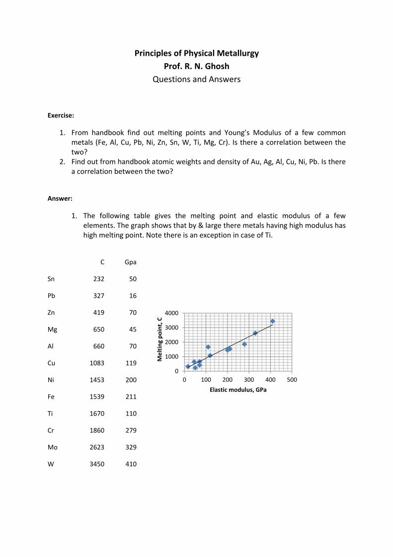
1. The following table gives the melting point and elastic modulus of a few elements. The graph shows that by & large there metals having high modulus has high melting point. Note there is an exception in case of Ti.
0
1000
2000
3000
4000
0 100 200 300 400 500
Melting point, C
Elastic modulus, GPa
C Gpa
Sn 232 50
Pb 327 16
Zn 419 70
Mg 650 45
Al 660 70
Cu 1083 119
Ni 1453 200
Fe 1539 211
Ti 1670 110
Cr 1860 279
Mo 2623 329
W 3450 410
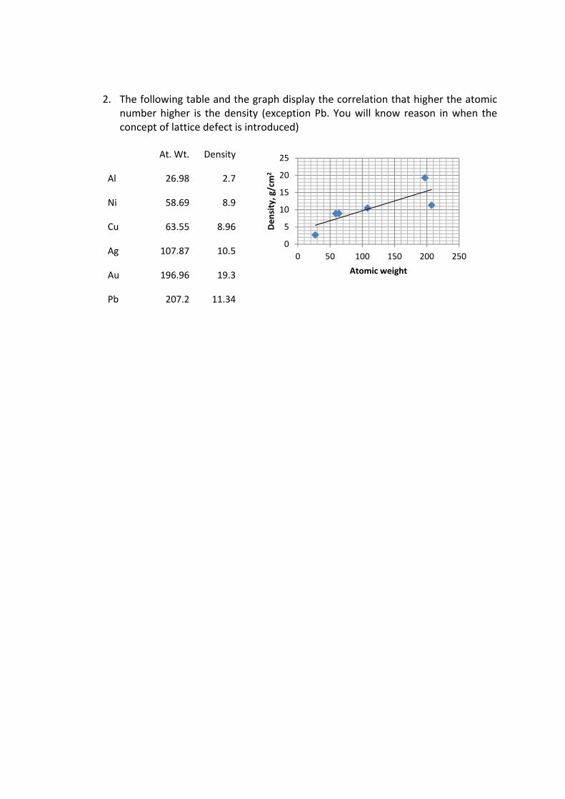
2. The following table and the graph display the correlation that higher the atomic number higher is the density (exception Pb. You will know reason in when the concept of lattice defect is introduced)
At. Wt. Density
Al 26.98 2.7
Ni 58.69 8.9
Cu 63.55 8.96
Ag 107.87 10.5
Au 196.96 19.3
Pb 207.2 11.34
0
5
10
15
20
25
0 50 100 150 200 250
Density, g/cm
2Atomic weight
Exercise:
1. What are the three primary bonds in materials? Which is the strongest? Why? 2. What is the electronic configuration of silicon atom? What type of bond do you expect here? 3. Inert gases have completely filled outer cell yet the boiling point of these increases with the
atomic number. Explain why it is so. 4. Find out from Handbook the melting points of metals in the 4th row of the periodic table (K‐
Zn). Which has the highest melting point? Explain this in terms of their electronic configurations.
5. Stiffness of C‐C bond is around 200N/m. Estimate its elastic modulus assuming the distance between the atoms to be 2x10‐10m. Which form of carbon has such a modulus?
Answer:
1. Three primary bonds are covalent, ionic and metallic. Boiling or melting points of
material are indicators of the strength of the bond. C‐C bond (covalent) in diamond is
possibly the strongest bond. Its melting point is ~3700°C. Its atomic diameter is
small. It is verified by x‐ray diffraction technique.
2. Atomic number of Si is 14. Its electronic configuration is 1s22s22p63s23p2. It has four
atoms in the outer cell like carbon. It also forms covalent bond. Its atomic diameter
is larger. The bond is not as strong as C‐C bond. Its melting pint is 1410°C.
3. Inert gases have completely filled outer cell. As you go down the group (from He to
Xe) the diameter increases as more orbits are added. As the diameter increases the
centre of orbital electrons will no longer coincide with the nucleus. The deviation
increases with the increase in diameter. Such atoms will therefore behave like
dipoles & promote bonding due to van der Waal force. Boiling point of He (Z=2) & Xe
(Z=54) are 4.2°K & 165°K respectively.
4. The fourth row of periodic table has several metals with atomic numbers varying
from 19 (K) to 30(Zn). Their melting points are given in the following table. Electronic
configuration of Ar (18) is 1s22s22p63s23p6. K atom has one more electron. Its
preferred site is 4s. The next atom Ca has 2 electron in 4s cell. Thereafter electrons
occupy 3d cell. Unpaired 3d electrons too participate in bond formation. If the
number of such electron increases the cohesive energy and hence melting point
increases. (Mn: exception?). In Zn all 3d electrons are paired & do not take part in
bonding. In this case number of electrons that take part in bond formation is less.
Therefore its melting point is low.
K 19
Ca 20
Sc 21
Ti 22 V 23 Cr 24
Mn25 Fe26 Co27 Ni28 Cu29 Zn30
64 833 1539 1668 1900 1875 1245 1539 1495 1453 1083 419
5. The bond is often visualized as a stiff spring which breaks without deformation. The
relation between the force (F) needed to snap a bond and the stiffness (strength) of
the bond (S) is given by F = S��where � is the minimum distance of separation at
which the bond breaks. Note that the dimension of stiffness is N/m. The cross
sectional area is of the order of a2. Therefore stress � = F/a2 = (S/a) (�/a) = E��where
E is modulus & � is strain. Thus E = S/a. If a is of the order of inter atomic distance
(a~0.2nm). E = 200/ (0.2x10‐9) = 1012 N/m2 = 1000 GPa.
Exercise:
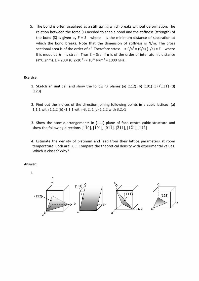
1. Sketch an unit cell and show the following planes (a) (112) (b) (101) (c) 111 (d) (123)
2. Find out the indices of the direction joining following points in a cubic lattice: (a) 1,1,1 with 1,1,2 (b) ‐1,1,1 with ‐3, 2, 1 (c) 1,1,2 with 3,2,‐1
3. Show the atomic arrangements in (111) plane of face centre cubic structure and show the following directions 110 , 101 , 011 , 211 , 121 , 112
4. Estimate the density of platinum and lead from their lattice parameters at room temperature. Both are FCC. Compare the theoretical density with experimental values. Which is closer? Why?
Answer:
1.
b
c
a
(112)
(101)
(123)
c
b a
111

2.
3.
4. The relation between density (�) & lattice parameter (a) is given by where
n= number of atom /unit cell, A = atomic weight & N=Avogrado number. For platinum A=192.09, n=4 fcc, N=6.02x10²³ & a=3.9239 Angstrom. On substitution�� = 21.45 gm/cc. Experimental density of Pt = 21.47. For lead A=207.2, n=4 fcc, a=4.9502Angstrom. On substitution in the expression for density �= 11.35 Experimental density =11.34. The estimation of x‐ray density in based on assumptions that all sites are occupied and atoms are hard. If there are vacancies in the lattice real density should be less than x‐ray density. If atoms are soft the density should be higher.
In a cubic crystal a direction [uvw] lies on a plane (hkl)
then hu+kv+lw=0. Using this three close packed
direction lying on (111) are [‐110], [‐101] & {0‐11].
These are shown by firm line. Three [112] directions
are [11‐2], [‐211] & [1‐21]. These are shown as dotted
lines.
110
101
011
211
121
211
If the coordinate of first point is u1, v1, w1 & the
second point is u2, v2, w2 the indices of the line
joining the two points can easily be shown with the
help of the diagram on the left is [u2‐u1, v2‐v1, w2‐
w1]. Line joining point 111 with 112 is shown try
others.
111
112
[001]
Exercise:
6. What is the basic difference between engineering & stereographic projections? Show with the help of a neat sketch the relation between a plane and a pole drawn on a projection plane.
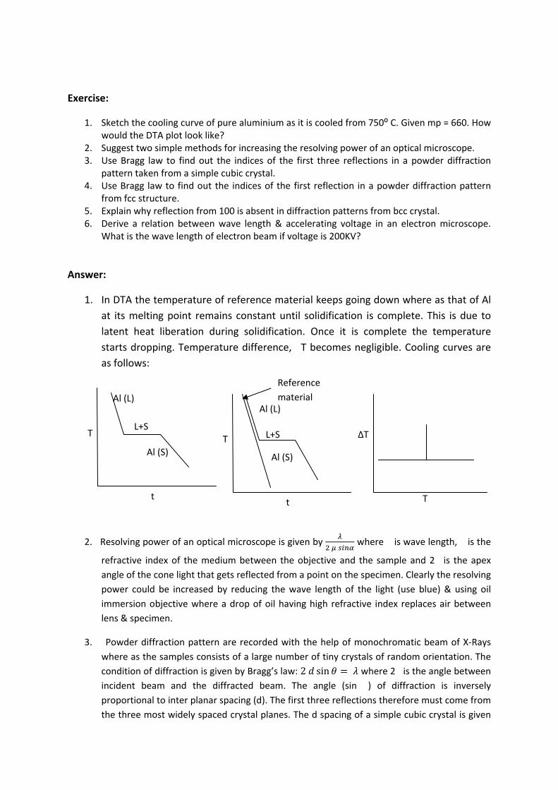
7. Draw a standard (001) projection of cubic crystal showing poles of low indices planes: (100), (110) and (111). List the [112] poles lying on plane (111)
8. You are given a standard 001 projection of a cubic crystal. Comment on the size of the crystal.
9. Why do you need to bring the two poles of stereographic projection on a longitude of the Wulff net by rotating it about its centre to measure the angle between the two?
Answer:
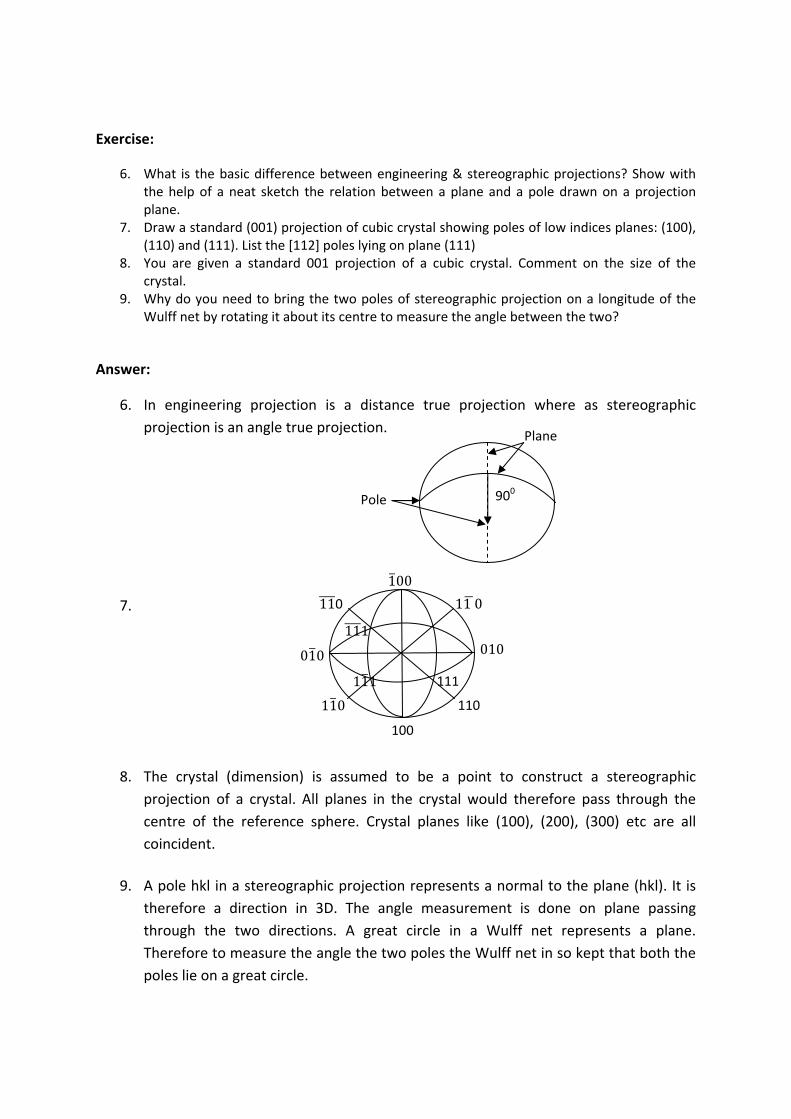
6. In engineering projection is a distance true projection where as stereographic
projection is an angle true projection.
7.
8. The crystal (dimension) is assumed to be a point to construct a stereographic
projection of a crystal. All planes in the crystal would therefore pass through the
centre of the reference sphere. Crystal planes like (100), (200), (300) etc are all
coincident.
9. A pole hkl in a stereographic projection represents a normal to the plane (hkl). It is
therefore a direction in 3D. The angle measurement is done on plane passing
through the two directions. A great circle in a Wulff net represents a plane.
Therefore to measure the angle the two poles the Wulff net in so kept that both the
poles lie on a great circle.
900
Plane
Pole
010
11 0
100
010
100
110
110 110
111
111
111
Exercise:
1. Sketch the cooling curve of pure aluminium as it is cooled from 750⁰ C. Given mp = 660. How would the DTA plot look like?
2. Suggest two simple methods for increasing the resolving power of an optical microscope. 3. Use Bragg law to find out the indices of the first three reflections in a powder diffraction
pattern taken from a simple cubic crystal. 4. Use Bragg law to find out the indices of the first reflection in a powder diffraction pattern
from fcc structure. 5. Explain why reflection from 100 is absent in diffraction patterns from bcc crystal. 6. Derive a relation between wave length & accelerating voltage in an electron microscope.
What is the wave length of electron beam if voltage is 200KV?
Answer:
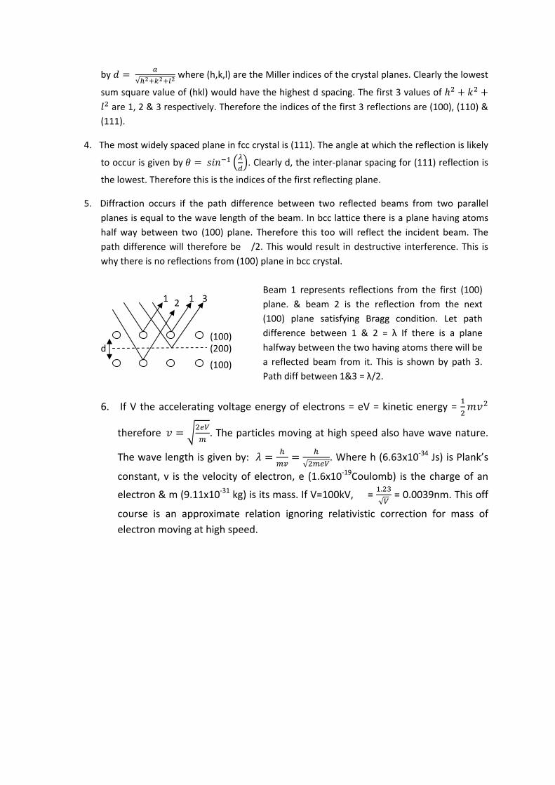
1. In DTA the temperature of reference material keeps going down where as that of Al
at its melting point remains constant until solidification is complete. This is due to
latent heat liberation during solidification. Once it is complete the temperature
starts dropping. Temperature difference, �T becomes negligible. Cooling curves are
as follows:
2. Resolving power of an optical microscope is given by
where � is wave length, � is the
refractive index of the medium between the objective and the sample and 2� is the apex
angle of the cone light that gets reflected from a point on the specimen. Clearly the resolving
power could be increased by reducing the wave length of the light (use blue) & using oil
immersion objective where a drop of oil having high refractive index replaces air between
lens & specimen.
3. Powder diffraction pattern are recorded with the help of monochromatic beam of X‐Rays
where as the samples consists of a large number of tiny crystals of random orientation. The
condition of diffraction is given by Bragg’s law: 2 sin where 2� is the angle between incident beam and the diffracted beam. The angle (sin �) of diffraction is inversely
proportional to inter planar spacing (d). The first three reflections therefore must come from
the three most widely spaced crystal planes. The d spacing of a simple cubic crystal is given
T
t
Al (L)
Al (S)
L+S T
t
Al (L)
Al (S)
L+S ΔT
T
Reference
material
by √
where (h,k,l) are the Miller indices of the crystal planes. Clearly the lowest
sum square value of (hkl) would have the highest d spacing. The first 3 values of
are 1, 2 & 3 respectively. Therefore the indices of the first 3 reflections are (100), (110) &
(111).
4. The most widely spaced plane in fcc crystal is (111). The angle at which the reflection is likely
to occur is given by . Clearly d, the inter‐planar spacing for (111) reflection is
the lowest. Therefore this is the indices of the first reflecting plane.
5. Diffraction occurs if the path difference between two reflected beams from two parallel
planes is equal to the wave length of the beam. In bcc lattice there is a plane having atoms
half way between two (100) plane. Therefore this too will reflect the incident beam. The
path difference will therefore be��/2. This would result in destructive interference. This is
why there is no reflections from (100) plane in bcc crystal.
6. If V the accelerating voltage energy of electrons = eV = kinetic energy =
therefore . The particles moving at high speed also have wave nature.
The wave length is given by: √
. Where h (6.63x10‐34 Js) is Plank’s
constant, v is the velocity of electron, e (1.6x10‐19Coulomb) is the charge of an
electron & m (9.11x10‐31 kg) is its mass. If V=100kV, � = .
√ = 0.0039nm. This off
course is an approximate relation ignoring relativistic correction for mass of
electron moving at high speed.
d (100)
(100)
(200)
1 2 1 3 Beam 1 represents reflections from the first (100)
plane. & beam 2 is the reflection from the next
(100) plane satisfying Bragg condition. Let path
difference between 1 & 2 = λ If there is a plane
halfway between the two having atoms there will be
a reflected beam from it. This is shown by path 3.
Path diff between 1&3 = λ/2.
Exercise:
7. If tensile stress strain plot beyond elastic limit is given by � = k�n show that necking (plastic
instability) sets in when true strain exceeds n.
8. Derive a relation between true strain and engineering strain.
9. The size of Brinell indentation taken on a steel specimen was found to be 5mm. Diameter of
the ball indenter is 10mm. Estimate its hardness.
10. Does necking take place during compressive loading?
11. Estimate the size of Vickers indentation on a specimen taken with 10kg load if its hardness is
200VHN. What will be the size of indent if load used were 30kg?
12. At what temperature does time dependent deformation become measurable?
13. What problem do you anticipate in measuring hardness of lead?
14. A specimen having initial length lo is deformed under tension in two stages. In stage I it is
deformed to a length of l1 and subsequently it is deformed to a length l2. Find out
engineering and true stain in each of these stages. Which of these follows additive rule if you
have to estimate final strain? Assume that deformation is uniform.
Answer:
1. Necking sets in during tensile test when the load (P) reaches its peak value. This is
given by P = ��A where � is the stress and A is the cross sectional area. Take log
& differentiate to getA
dAd
P
dP
. This becomes zero when P is maximum.
Since reduction in area (‐dA/A) is equal to true strain increment (d�) it gives:
d
d. Since � = k�n it can be shown:
/1 nknkd
d nn Therefore:
strain at which necking sets in is given by �= n.
2. True strain (d�) is defined as change in length (dl) over instantaneous length (l).
Let initial length be lo and final length l so that engineering strain (e) is = (l‐l0)/l0.
Therefore to obtain true strain one has to integrate the following equation
between limits lo & l. el
dll
l
l
l
dll
l
1lnlnln0
0
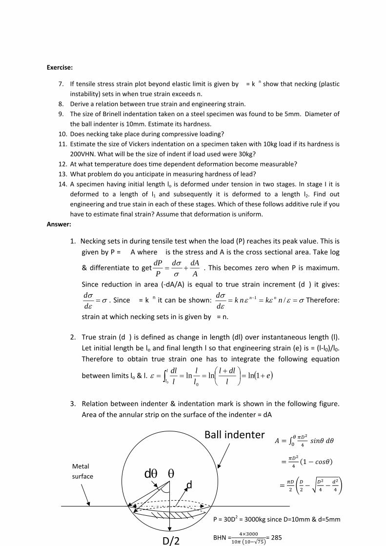
3. Relation between indenter & indentation mark is shown in the following figure.
Area of the annular strip on the surface of the indenter = dA
Metal
surface
D/2
d
Ball indenter
d
1
P = 30D2 = 3000kg since D=10mm & d=5mm
BHN =√
= 285

4. Necking does not occur under compressive load because stress decreases with
strain (note that in this case cross section area increases with deformation).
There may be instability of another kind. This is known as buckling. It is
determined by length to diameter ratio. Cylindrical test piece with higher height
to diameter ratio is prone to such instability.
5. Vickers hardness VHN = P/A where P is load and A in area of indentation mark.
The indenter is a square based pyramid with apex angle =136⁰. If the diagonal of
the indentation is d the area of indentation can be obtained as follows:
6. Creep is a time dependent deformation. It is a strong function of temperature. It becomes
measurable when test temperature is greater than 0.5 times the melting point of the metal
in degree Kelvin.
7. Melting point of lead is low (~327°C). Tm = 600°K. Room temperature (~300°K) = 0.5Tm.
Therefore it would creep and the size of indentation will increase with time. A more precise
control of time is required to get reproducible result.
8. Engineering strain in stage I = e1 = and that in stage II = e2 = whereas total strain = et
= However true strain in stage I = �1 = and that in stage II = �2 = and total
strain = �t = It is easily noted that in case of true strain �t =
. This is not true for engineering strain.
Length of one side of indentation = d/√2 if the apex angle = θ using simple trigonometric relation the area of one of the triangular faces of the indentation can be shown to be =
2sin
1
22
2
d. There are 4 such faces.
Therefore VHN defined as P/A is given by:
22
854.1
2sin2
d
P
d
P
. If P =10kg d =
0.304mm & if P=30kg d=0.527mm
Vertical
section
d
h
Top view
Exercise:
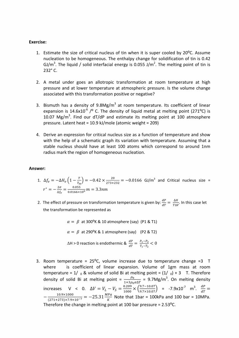
1. Estimate the size of critical nucleus of tin when it is super cooled by 20⁰C. Assume nucleation to be homogeneous. The enthalpy change for solidification of tin is 0.42 GJ/m3. The liquid / solid interfacial energy is 0.055 J/m2. The melting point of tin is 232° C.
2. A metal under goes an allotropic transformation at room temperature at high pressure and at lower temperature at atmospheric pressure. Is the volume change associated with this transformation positive or negative?
3. Bismuth has a density of 9.8Mg/m3 at room temperature. Its coefficient of linear expansion is 14.6x10‐6 /⁰ C. The density of liquid metal at melting point (271⁰C) is 10.07 Mg/m3. Find our dT/dP and estimate its melting point at 100 atmosphere pressure. Latent heat = 10.9 kJ/mole (atomic weight = 209)
4. Derive an expression for critical nucleus size as a function of temperature and show with the help of a schematic graph its variation with temperature. Assuming that a stable nucleus should have at least 100 atoms which correspond to around 1nm radius mark the region of homogeneous nucleation.
Answer:
1. ∆ ∆ 1 0.42 0.0166 GJ/m3 and Critical nucleus size =
∗∆
.
.3.3
2. The effect of pressure on transformation temperature is given by: ∆
∆. In this case let
the transformation be represented as
3. Room temperature = 25⁰C, volume increase due to temperature change =3��T where ���is coefficient of linear expansion. Volume of 1gm mass at room temperature = 1/�0 & volume of solid Bi at melting point = (1/�0) + 3��T. Therefore
density of solid Bi at melting point = ∆ = 9.7Mg/m3. On melting density
increases �V < 0. ∆ . . .
. . = ‐7.9x10‐7 m3.
.
.25.31 Note that 1bar = 100kPa and 100 bar = 10MPa.
Therefore the change in melting point at 100 bar pressure = 2.53⁰C.
at 300⁰K & 10 atmosphere (say) (P1 & T1)
at 290⁰K & 1 atmosphere (say) (P2 & T2)
H > 0 reaction is endothermic & 0
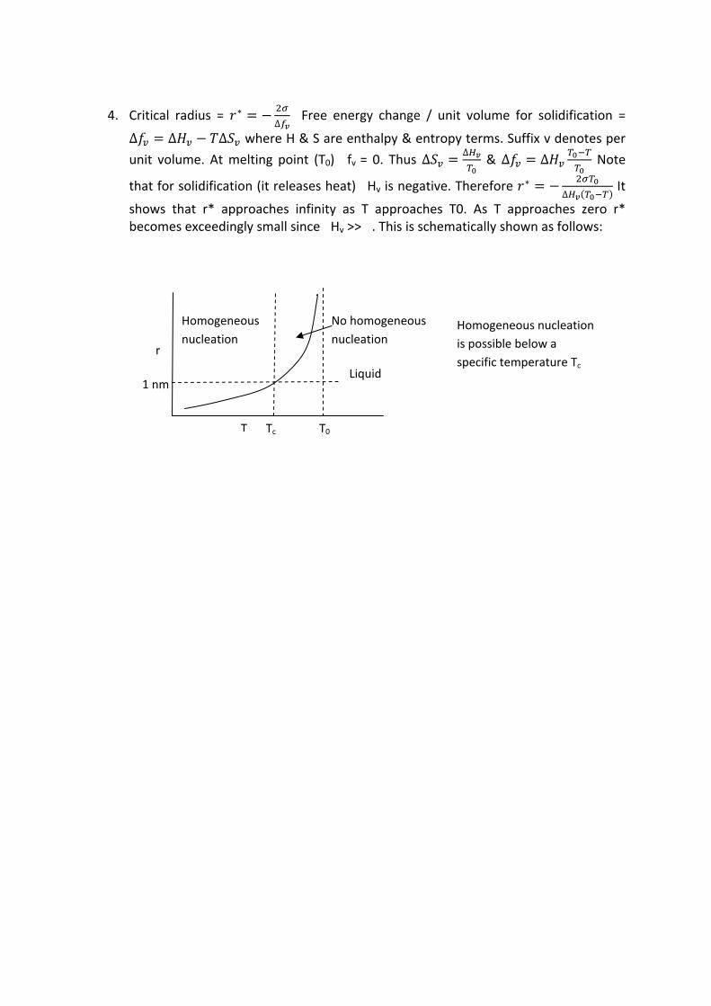
4. Critical radius = ∗∆
Free energy change / unit volume for solidification =
∆ ∆ ∆ where H & S are enthalpy & entropy terms. Suffix v denotes per
unit volume. At melting point (T0) �fv = 0. Thus ∆∆
& ∆ ∆ Note
that for solidification (it releases heat) �Hv is negative. Therefore ∗∆
It
shows that r* approaches infinity as T approaches T0. As T approaches zero r* becomes exceedingly small since �Hv >> �. This is schematically shown as follows:
r
T T0
1 nm
Homogeneous
nucleation
Liquid
No homogeneous
nucleationHomogeneous nucleation
is possible below a
specific temperature Tc
Tc
Exercise:
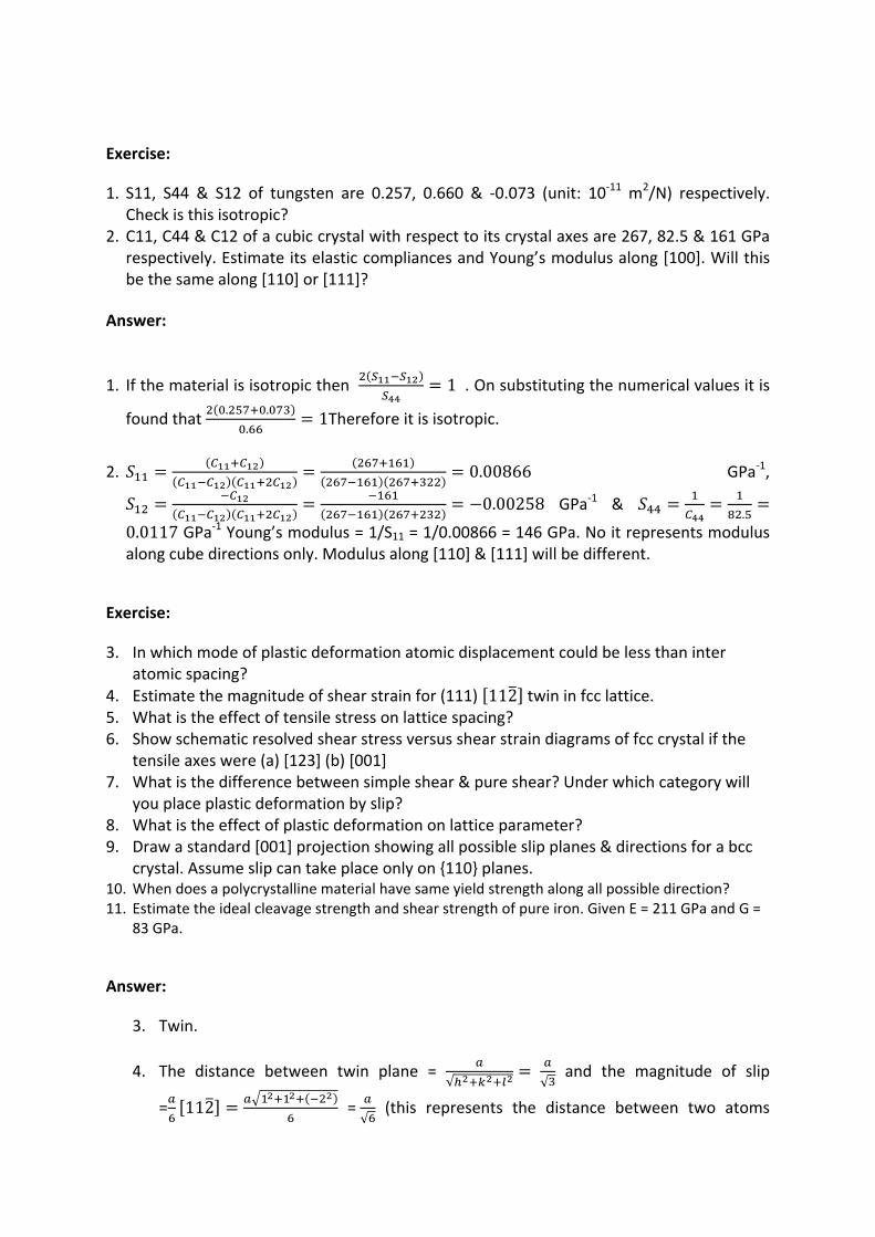
1. S11, S44 & S12 of tungsten are 0.257, 0.660 & ‐0.073 (unit: 10‐11 m2/N) respectively. Check is this isotropic?
2. C11, C44 & C12 of a cubic crystal with respect to its crystal axes are 267, 82.5 & 161 GPa respectively. Estimate its elastic compliances and Young’s modulus along [100]. Will this be the same along [110] or [111]?
Answer:
1. If the material is isotropic then 1 . On substituting the numerical values it is
found that . .
.1Therefore it is isotropic.
2. 0.00866 GPa‐1,
0.00258 GPa‐1 & .
0.0117 GPa‐1 Young’s modulus = 1/S11 = 1/0.00866 = 146 GPa. No it represents modulus along cube directions only. Modulus along [110] & [111] will be different.
Exercise:
3. In which mode of plastic deformation atomic displacement could be less than inter atomic spacing?
4. Estimate the magnitude of shear strain for (111) 112 twin in fcc lattice. 5. What is the effect of tensile stress on lattice spacing? 6. Show schematic resolved shear stress versus shear strain diagrams of fcc crystal if the
tensile axes were (a) [123] (b) [001] 7. What is the difference between simple shear & pure shear? Under which category will
you place plastic deformation by slip? 8. What is the effect of plastic deformation on lattice parameter? 9. Draw a standard [001] projection showing all possible slip planes & directions for a bcc
crystal. Assume slip can take place only on {110} planes. 10. When does a polycrystalline material have same yield strength along all possible direction? 11. Estimate the ideal cleavage strength and shear strength of pure iron. Given E = 211 GPa and G =
83 GPa.
Answer:
3. Twin.
4. The distance between twin plane = √
√ and the magnitude of slip
= 112 =√ (this represents the distance between two atoms

along 112 ). Shear strain is the ratio of magnitude of slip to the distance between
the two planes √
√ √0.71
5. Lattice spacing increases with tensile stress till it reaches its elastic limit. Elastic strain
is equal to the ratio of change in lattice spacing along the tensile axis to its original
value =∆
.
6.
7. Simple shear represents displacement or slip on a plane along a specified direction.
This is schematically represented as follow:
8. Plastic deformation does not alter crystal structure or its dimension. Lattice
parameter after deformation is still the same.
9.
RSS
Shear strain
[123]
RSS [001]
Shear
In case of [123] initially resolved shear
stress reaches its critical value for a
single slip system. Therefore all 3
stages of deformation are seen. In
case of [001] RSS reaches CRSS
simultaneously on several slip system
(8 to be precise). Therefore 3 distinct
stages are not seen.
Slip systems of bcc crystal are {101} 111 There
are 12 such system. These are shown in standard
projection. For a pole lying within a stereographic
triangle slip plane & direction having maximum
resolved shear stress lie in the adjacent triangle. This
is shown for one case where the pole is marked as a
circle. The slip plane is 101 and slip direction is
[111].
100
010001
110
101
01
100
010
110 110
110
011
101
111
111111
111
x
Simple shear: x is normal to plane on
which shear has taken place & y is
displacement. Displacement gradient is:
. Using the notation used it
is e12. All other components are zero.
The matrix is not symmetric. Slip is a
simple shear
0 00 0 00 0 0
0 2⁄ 02⁄ 0 00 0 0
0 2⁄ 02⁄ 0 0
0 0 0
Pure shear: simple shear (eij) is equal to sum of pure shear
(ij) and rotation (ij) as shown above. This makes the
strain matrix symmetric.
x
/2
/2

10. Strength of a crystal may vary with the direction of loading. Polycrystalline metals
may have a large number of grains. Its properties will be a function of the entire
group. If these are randomly oriented then one would expect its properties to be
isotropic.
11. Ideal shear strength 13.21 . For estimating cleavage strength
please see problem 15 of chapter 1. This gives & since
a is nearly equal to a0. Thus√ .
67 . These are nearly
two orders of magnitude higher than the real strength of iron.
Exercise:
1. FCC crystals have more packing density than BCC crystal yet why solubility of carbon in FCC form of iron is higher than in its BCC form?
2. What is the effect of temperature on the concentration of vacancy? 3. If the ratio of iron ions to oxygen ions is 0.994 in FeO, what fraction of Fe sites are filled
with Fe3+ ions? What is the ratio of Fe3+ to O2‐ ions? 4. What are the major differences between an edge & screw dislocation? Which of these
can cross slip? Answer:
1. FCC has the maximum packing density (74%). However the interstitial sites where the carbon atoms are located are larger than those in BCC structure. Packing density in BCC is relatively low (68%). However there is more number of interstitial sites for every Fe atom. The gaps are distributed amongst more number of sites. Therefore these are too small to accommodate carbon atoms. This is why solubility is low.
2. The fraction of vacant lattice sites in a crystal is given by where k is
Boltzmann constant, qv is the energy needed to create a vacancy and T is the
temperature in degree Absolute. As the T increases too increases.
3. Ionic crystals must maintain charge neutrality. In this iron oxide fraction of vacant Fe2+
sites = 1‐0.994 = 0.006. The reason that stoichiometry is not maintained indicates that for every O2‐ vacancy there are 2 Fe3+ ions. Thus the fraction of vacant O2‐ sites = 0.003. Note that to maintain charge neutrality there could have been 0.006 vacant O2‐ sites. In that event stoichiometry would have been FeO.
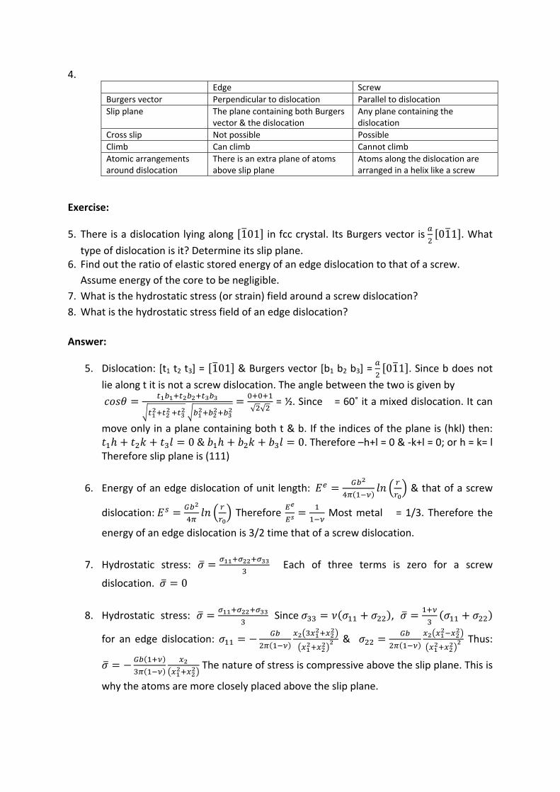
4. Edge Screw
Burgers vector Perpendicular to dislocation Parallel to dislocation
Slip plane The plane containing both Burgers vector & the dislocation
Any plane containing the dislocation
Cross slip Not possible Possible
Climb Can climb Cannot climb
Atomic arrangements around dislocation
There is an extra plane of atoms above slip plane
Atoms along the dislocation are arranged in a helix like a screw
Exercise:
5. There is a dislocation lying along 101 in fcc crystal. Its Burgers vector is 011 . What
type of dislocation is it? Determine its slip plane. 6. Find out the ratio of elastic stored energy of an edge dislocation to that of a screw.
Assume energy of the core to be negligible.
7. What is the hydrostatic stress (or strain) field around a screw dislocation?
8. What is the hydrostatic stress field of an edge dislocation?
Answer:
5. Dislocation: [t1 t2 t3] = 101 & Burgers vector [b1 b2 b3] = 011 . Since b does not
lie along t it is not a screw dislocation. The angle between the two is given by
√ √
= ½. Since � = 60˚ it a mixed dislocation. It can
move only in a plane containing both t & b. If the indices of the plane is (hkl) then: 0& 0. Therefore –h+l = 0 & ‐k+l = 0; or h = k= l
Therefore slip plane is (111)
6. Energy of an edge dislocation of unit length: & that of a screw
dislocation: Therefore Most metal � = 1/3. Therefore the
energy of an edge dislocation is 3/2 time that of a screw dislocation.
7. Hydrostatic stress: Each of three terms is zero for a screw
dislocation. 0
8. Hydrostatic stress: Since ,
for an edge dislocation: & Thus:
The nature of stress is compressive above the slip plane. This is
why the atoms are more closely placed above the slip plane.
Exercise:
9. Assume that dislocations are arranged in an array in three dimensions described as a
cubic lattice. If average number of dislocations intersecting a plane is � /unit area show
that the average distance between two dislocations is proportional to √ (1/�).
10. Dislocation density of annealed metal is 1012 m‐2. Find out elastic stored energy per
unit volume.
11. Elastic stored energy / unit length of an edge dislocation is given by
. Does this mean it can approach infinity as r becomes very large?
12. What is the difference between a kink and a jog? An edge dislocation crosses
another dislocation which is perpendicular to the slip plane. Show with neat diagram the
effect of such an interaction.13. A perfect dislocation moving on plane 111 interacts with
another moving on 111 . What are the different reactions possible? Which of these are
Lomer locks?
14. On what planes can a screw dislocation having Burgers vector
111 could move in a BCC crystal? What will be the slip plane if it were an edge
dislocation?
Answer:
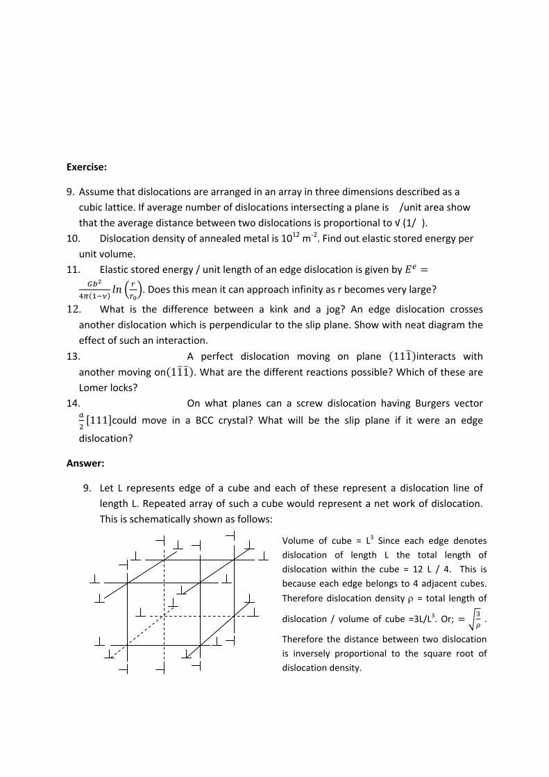
9. Let L represents edge of a cube and each of these represent a dislocation line of
length L. Repeated array of such a cube would represent a net work of dislocation.
This is schematically shown as follows:
Volume of cube = L3 Since each edge denotes
dislocation of length L the total length of
dislocation within the cube = 12 L / 4. This is
because each edge belongs to 4 adjacent cubes.
Therefore dislocation density = total length of
dislocation / volume of cube =3L/L3. Or; .
Therefore the distance between two dislocation
is inversely proportional to the square root of
dislocation density.
10. Previous problem shows that the average distance between two dislocation = L. The
stress field of a dislocation can be assumed to extend over a distance = L/2.
Or; 0.86 . which is approximately: Energy of a dislocation
consists of two parts. U = Ucore + Ustrain & The strain energy =
where � represents angle between dislocation and Burgers vector.
For edge dislocation ��= �/2 whereas for screw �=0. To estimate energy of a
dislocation let us assume b=0.25nm and r0 = 5b and R = �‐0.05 = 10‐6 Therefore
.800 0.63 0.5 . Assume
G=50GPa Energy / unit length of dislocation = 0.5 50 10 0.0625 10
J/m2 = 1.56 x 10‐9 J/m Therefore elastic stored energy / unit volume = U� = 1.56 x 10‐9
x 1012 = 1.56 kJ/m3
11. No. Because dislocations do not occur in isolation. If the average distance between
dislocations is L average value of r = 0.5L. Therefore energy of dislocations is always
finite. Approximately this is equal to 0.5 Gb2.
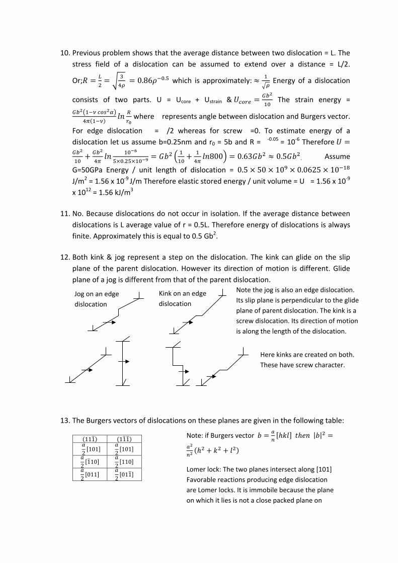
12. Both kink & jog represent a step on the dislocation. The kink can glide on the slip
plane of the parent dislocation. However its direction of motion is different. Glide
plane of a jog is different from that of the parent dislocation.
13. The Burgers vectors of dislocations on these planes are given in the following table:
111 111
2101
2101
2110
2110
2011
2011
Note the jog is also an edge dislocation.
Its slip plane is perpendicular to the glide
plane of parent dislocation. The kink is a
screw dislocation. Its direction of motion
is along the length of the dislocation.
Jog on an edge
dislocation
Kink on an edge
dislocation
Here kinks are created on both.
These have screw character.
Note: if Burgers vector | |
Lomer lock: The two planes intersect along [101]
Favorable reactions producing edge dislocation
are Lomer locks. It is immobile because the plane
on which it lies is not a close packed plane on
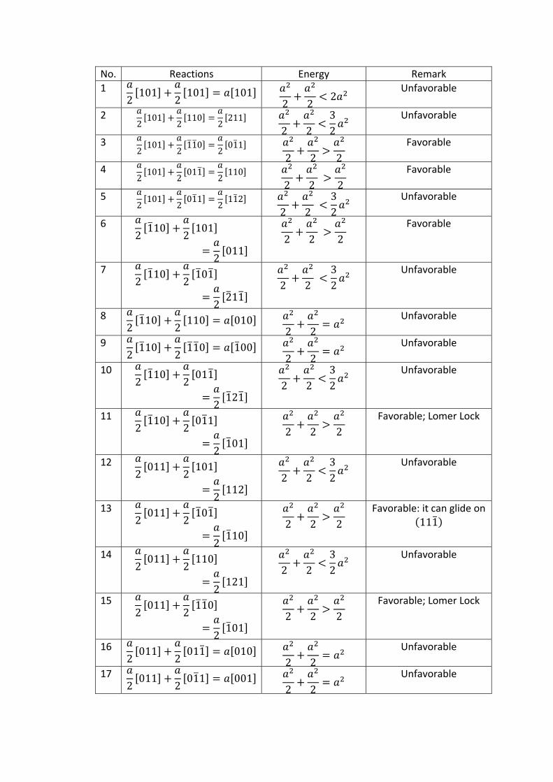
No. Reactions Energy Remark
1 2101
2101 101
2 22
Unfavorable
2 2101
2110
2211
2 232
Unfavorable
3 2101
2110
2011
2 2 2
Favorable
4 2101
2011
2110
2 2 2
Favorable
5 2101
2011
2112
2 232
Unfavorable
6 2110
2101
2011
2 2 2
Favorable
7 2110
2101
2211
2 232
Unfavorable
8 2110
2110 010
2 2
Unfavorable
9 2110
2110 100
2 2
Unfavorable
10 2110
2011
2121
2 232
Unfavorable
11 2110
2011
2101
2 2 2
Favorable; Lomer Lock
12 2011
2101
2112
2 232
Unfavorable
13 2011
2101
2110
2 2 2
Favorable: it can glide on
111
14 2011
2110
2121
2 232
Unfavorable
15 2011
2110
2101
2 2 2
Favorable; Lomer Lock
16 2011
2011 010
2 2
Unfavorable
17 2011
2011 001
2 2
Unfavorable
14. Let the slip plane be one of the 12 {110} planes. Dislocation & the Burgers vector
must lie on slip plane. The Possible glide planes are 110 , 101 , 011 . The best
way to check if dot product of Burgers vector & plane normal is equal to zero (b.n =
0). If the slip plane were of type {112} the slip plane for this case would be
211 , 121 & 112 . Try to find out the possible slip plane of type {123}.
If it were an edge dislocation one must specify its direction. It could glide only if it
lies on one of the slip planes. For example an edge dislocation 111 lying along
211 could glide on 011 . Find other possibilities.
Exercise:
15. An fcc crystal is pulled along [123]. What is the possible combination of glide plane &
direction? Estimate the force on the mobile dislocation if applied tensile stress is
100MPa & lattice parameter = 0.36nm.16. What is the force acting on a dislocation b [010] lying along [100] if the applied stress
is given by0 0 00 00 0 0
? Will this help it glide?
17. An edge dislocation moving on a crystal plane stops at an obstacle. A second
dislocation having the same Burgers vector & lying on the same plane approaches the same on application of a shear stress of magnitude 140MPa. Estimate the distance of separation if E = 210GPa, Poisson ratio = 0.3 & lattice parameter = 0.362nm. What will be the distance between the two if they were screw dislocation?
18. A dislocation is pinned between two obstacles spaced 1micron apart. What will be the magnitude of stress to bow the dislocation into a semi circle? Hence estimate its yield strength. Given G = 100 GPa, Burgers vector = 0.25nm
19. Nickel sheet is being rolled at room temperature in a rolling mill (diameter = 50cm, rpm = 200). Initial thickness is 20mm and thickness after rolling is 10mm. Estimate average strain rate, energy that will be stored in material if final dislocation density is 1011/cm2 , total energy / unit volume spent during rolling (assume flow stress = 300MPa), adiabatic temperature rise if specific heat = 0.49J/g/K
20. Iron (a = 0.286nm and G = 70GPa) is deformed to a shear strain of 0.3. What distance a dislocation could move, if dislocation density remains constant at 1014 /m2? What will be the average dislocation velocity if strain rate is 10‐2 /s? Estimate its shear strength.
21. Polycrystalline aluminum with average grain size of 10micron is subjected to shear stress of 50MPa. If a dislocation source located at the centre of a grain emits dislocations which pile up at the boundary what is the stress it would experience? (G=70GPa, b=0.3nm)
Answer:
15. Look at the standard project & identify the the slip plane & direction having highest
resolved shear stress. In this case it is 111 101 . Therefore resolved shear
stress: . √ √ √
& √ √ √
The force on dislocation which is mobile is given by 100.
√10
√=0.012 N/m
16. The force on a dislocation is given by The subscripts can have
values 1, 2 or 3. Since only non zero compoments of �, b & t are �22, b2 & t1.
Therefore subscript i has to be 3 ( 1
0& 1, 1 Thus This being an edge
dislocation can climb due to a force acting along its Burgers vector. Since the force is
against x3 it can help it climb down.
17. Assume that the dislocations lie on (001) plane. Let this be the glide plane. Since x2 =
0 only non zero force acting on the dislocation is given by Since both
dislocations have positive b they would repel each other. Here it is balanced by a
force acting on the second dislocation which is �b. Therefore the distance between
the two is given by .
.59.7
18. Shear stress�� is given by . 25 This represents shear
strength. YS is usually = 2 x shear stregth = 50MPa.
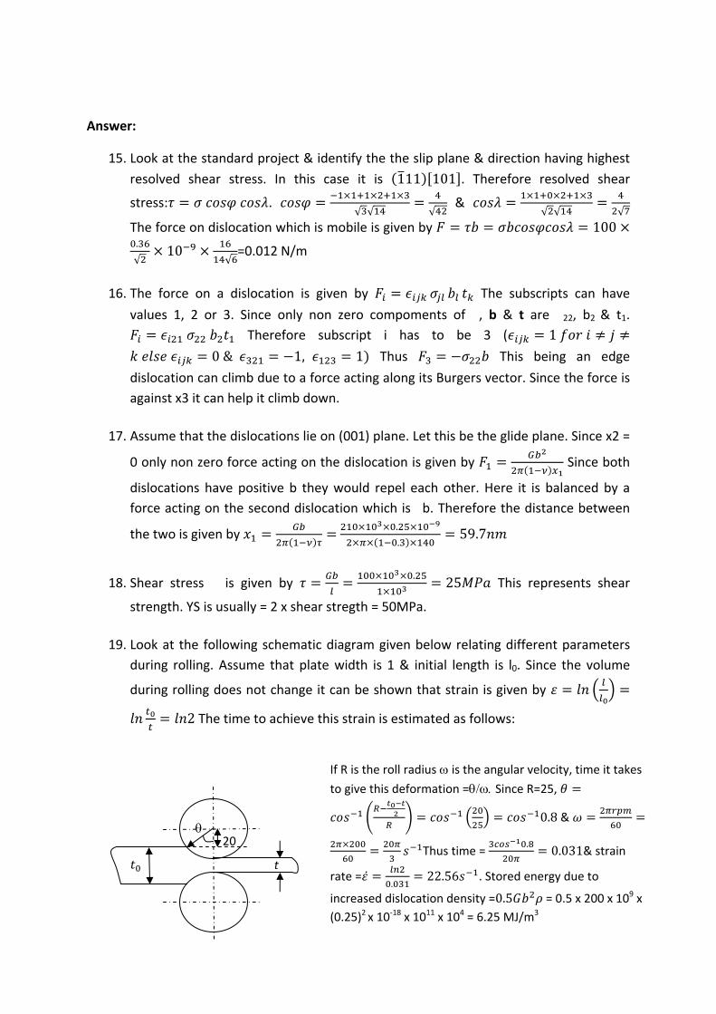
19. Look at the following schematic diagram given below relating different parameters
during rolling. Assume that plate width is 1 & initial length is l0. Since the volume
during rolling does not change it can be shown that strain is given by
2 The time to achieve this strain is estimated as follows:
If R is the roll radius is the angular velocity, time it takes
to give this deformation =Since R=25,
0.8 &
Thus time = .
0.031& strain
rate =.
22.56 . Stored energy due to
increased dislocation density =0.5 = 0.5 x 200 x 109 x
(0.25)2 x 10‐18 x 1011 x 104 = 6.25 MJ/m3
t
20
Energy spent =flow stress x strain = 300 ln(2) = 208 MJ/m3. This shows only a very small amount of the total enegy is stored within the metal. Bulk of it is dissipated as
heat. Assuming the process of rolling is adiabatic temperature increase∆.
.46
20. Total strain (�) is given by ̅ where � is dislocation density, b is Burgers vector
& ̅ is the average glide distance of dislocation. Burgers vector b = a/√3 =0.248nm.
Therefore ̅ .
.1.21 10 . This is equal to 1.21micron
which is less than its grain size. The average velocity = 1.21x10‐3 m/s.
21. The force experienced by a dislocation due to another at a distance x on the slip
plane is given by . Since the dislocation source is at the centre of the
grain, it is at a distance = d/2 from the disloaction at grain boundary. Therefore
x=d/2. Thus This may be assumed to be the resisting force acting on the
source. The net force acting on the source = �b‐F which is 50
10 0.3 10 .
.0.015 0.00057 0.014 /
Exercise:
22. Estimate the distance between dislocations in a tilt boundary of alumunium if the
misorientation angle is 5⁰. Given lattice parameter of Al = 0.405nm. Crystal structure
is fcc.
23. A more precise expression for low energy grain biundary is given by
where A is an constant. This is valid over the range 0 < ��< 10⁰.
Find a reasonable estimate of A. Given lattice parameter of Ni (fcc) = 0.35nm, G =
76MPa Poisson ratio = 0.3 (Hint: assume dislocation core radius as 5b & the
minimum distance between dislocation to be twice this. The doslocation core
energy )
24. Estimate the dislocation spacing and energy of a low angle boundary in copper
crystal (fcc b = 0.25nm) if tilt angle = 1⁰. Given G = 48MPa & � = 0.3
25. Use the expression given in problem 2 to find our the tilt angle (�max) at which the
enegry of a low angle boundary is the maximum. Hence show that
1
26. Estimate the energy of the free surface of polycrystalline copper from its heat of
sublimation. Does this vary from grain to grain? Given Ls = 338 kJ/mole; a = 0.36 nm
Answer:
22. Burgers vector of a dislocation in a tilt boundary = 110√
.
√0.29
The spacing between the two dislocations is given by . 180 3.32
23. Burgers vector =√
.
√0.25 When the dislocations are 10b apart energy of
the low angle boundary = (since boundary consists of one dislocation of unit
length at every distance of h). h = 2r0 =10b. Thus where �
= b/10b = 0.1rad & A =‐1.42
24. Since poisson ratio is same as in the previous problem 1.42
.
. 1.42 0.13 J/m2
25. Differentiating the expression for E: 0 Thus
1 On substituting the magtitude of A from the previous problem
5.1⁰ & (note A = 1+ln �max)
1 1
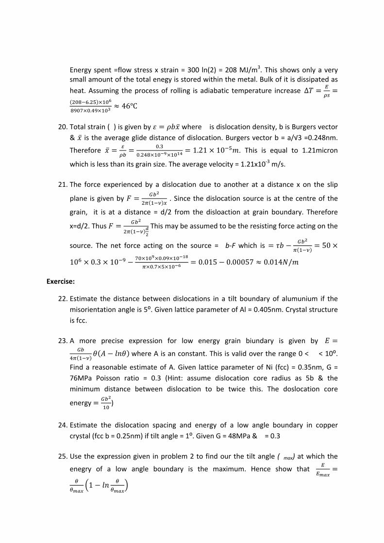
26. Energy of the free surface depends on the way atoms are arranged. This varies from
grain to grain depending on their orientations. If Z is the cordination number, the
number of bonds of type AA in one mole of pure metal = where N0 is Avogrado
number. If � is the energy of one bond, where Ls is heat of sublimation.
The free surface has a set of broken bonds. Energy of a broken bond is
approximately �/2. The number depends on the indices of the top surface. If it were
(111) there will be 3 broken bonds / atom (There are 6 bonds on the plane 3 beneath
& 3 above it). Energy of free surface is therefore = 3�/2 J/atom. If na is number of
atom / unit area surcae free energy The arrangements of atom in (111)
plane is shown below. On substituion in expression for √
√
2.5 /
√2
60⁰
0.5
0.5√2
60
4
√3
Exercise:
1. If iron is kept at 1200˚K in a carburizing atmosphere for 8hrs to obtain a carbon concentration of 0.75 at a depth of 0.5mm. Find the time it would take to reach same carbon concentration at depth of 7.5mm at 1250˚K. (Given D0 = 0.2x10
‐4 m2/s & Q = 143kJ/mole/˚K)
2. A steel containing 0.2 % carbon was heated to 950˚K for 15 hours. Find the depth of layer in which there is no carbide. Assume that steel consists of ferrite and carbide. The solubility of carbon in ferrite at this temperature is 0.015% and % C at the surface is negligible. (Given D0 = 2x10
‐6 m2/s & Q = 84.4kJ/mole/˚K) 3. The concentration of carbon on the surface of iron is maintained at 1.00% at
1175˚K for 2hours. Estimate the depth at which % C would be 0.5%. Use the diffusivity values given in question1. Assume initial carbon content of iron to be negligible.
Answer:
1. If iron is kept at high temperature in an environment having high carbon potential it
diffuses into iron. The depth of carburization (x) is proportional to√ . Therefore
Since Therefore
.
. .=10.14 hours
2. If initial carbon in steel is Ci & soluble carbon in ferrite is C� amount carbon to
removed / unit cross section through a distance dx = (Ci‐C�)dx = flux of carbon atom
in time dt = ‐Jdt = Assuming carbon concentration at surface as 0
Thus or; 2
10.
4.55 10 m2/s Now Ci = 0.2 & Ca = 0.015 Therefore
. .
. .0.00063m = 0.63mm
3. Carbon content at surface Cs = 1.00, Initial carbon C0 = 0.0 & carbon content at a
distance x C=0.5
√ Or,
. – .
. √ Or,
√0.477
Or, 0.477 2 0.2 10.
2 3600 =0.000425m
=0.445mm
Exercise:
1. Nickel, Aluminium & Copper have face cantered cubic structure yet Ni is soluble in copper whereas Al has only a limited solubility. Explain why it is so?
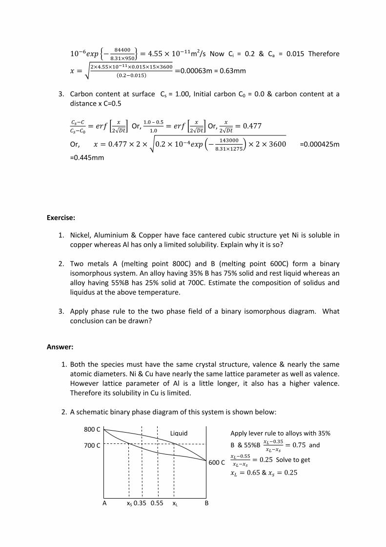
2. Two metals A (melting point 800C) and B (melting point 600C) form a binary isomorphous system. An alloy having 35% B has 75% solid and rest liquid whereas an alloy having 55%B has 25% solid at 700C. Estimate the composition of solidus and liquidus at the above temperature.
3. Apply phase rule to the two phase field of a binary isomorphous diagram. What conclusion can be drawn?
Answer:
1. Both the species must have the same crystal structure, valence & nearly the same atomic diameters. Ni & Cu have nearly the same lattice parameter as well as valence. However lattice parameter of Al is a little longer, it also has a higher valence. Therefore its solubility in Cu is limited.
2. A schematic binary phase diagram of this system is shown below:
800 C
700 C
600 C
Liquid
A B xS xL 0.35 0.55
Apply lever rule to alloys with 35%
B & 55%B.
0.75 and .
0.25 Solve to get
0.65 & 0.25
3. Phase rule at constant pressure states P+F =C+1. In the two phase field P=2, it is a
binary system therefore C=2. On substitution in the above expression F=1. It has only
one degree of freedom. If temperature is constant compsitions of coexisting liquid &
solid are fixed. This is given by the intersection of the tie line at the specified
temperature. If you specify composition of the solid the composition of coexisting
liquid and the temperature are fixed.
Exercise:
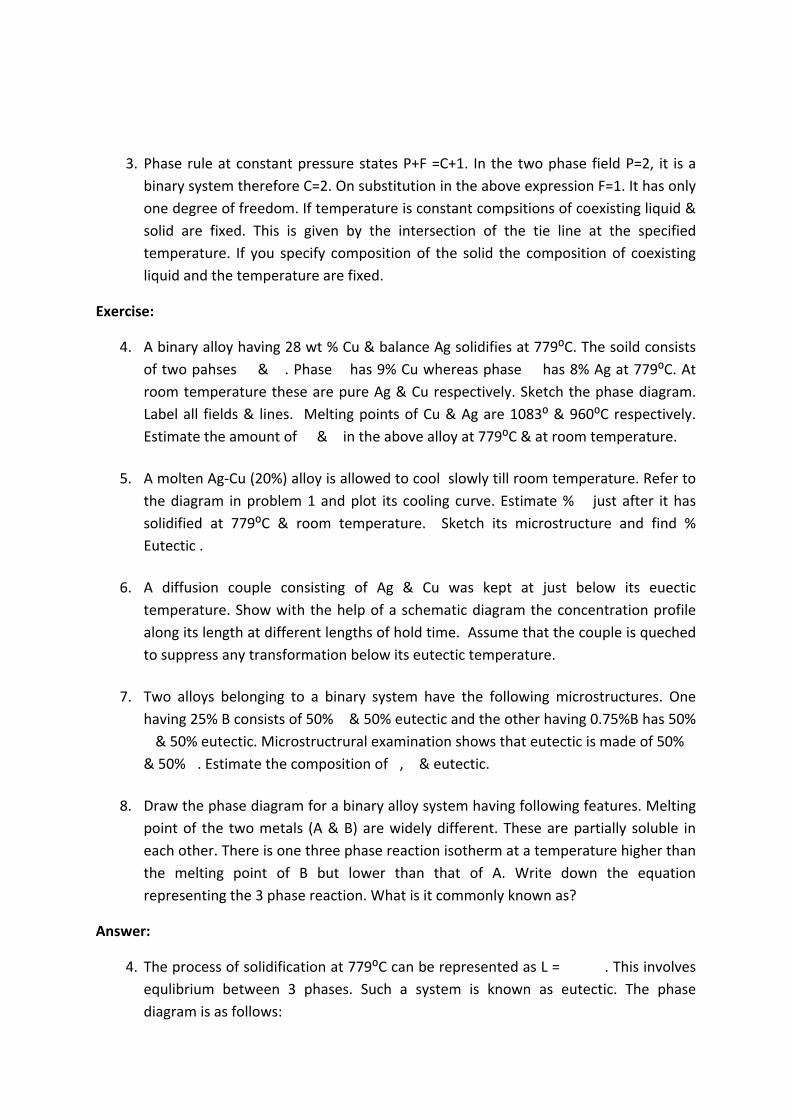
4. A binary alloy having 28 wt % Cu & balance Ag solidifies at 779⁰C. The soild consists
of two pahses ��&��. Phase � has 9% Cu whereas phase�� has 8% Ag at 779⁰C. At
room temperature these are pure Ag & Cu respectively. Sketch the phase diagram.
Label all fields & lines. Melting points of Cu & Ag are 1083⁰ & 960⁰C respectively.
Estimate the amount of ��& � in the above alloy at 779⁰C & at room temperature.
5. A molten Ag‐Cu (20%) alloy is allowed to cool slowly till room temperature. Refer to
the diagram in problem 1 and plot its cooling curve. Estimate % � just after it has
solidified at 779⁰C & room temperature. Sketch its microstructure and find %
Eutectic .
6. A diffusion couple consisting of Ag & Cu was kept at just below its euectic
temperature. Show with the help of a schematic diagram the concentration profile
along its length at different lengths of hold time. Assume that the couple is queched
to suppress any transformation below its eutectic temperature.
7. Two alloys belonging to a binary system have the following microstructures. One
having 25% B consists of 50% � & 50% eutectic and the other having 0.75%B has 50%
� & 50% eutectic. Microstructrural examination shows that eutectic is made of 50% �
& 50% �. Estimate the composition of �, � & eutectic.
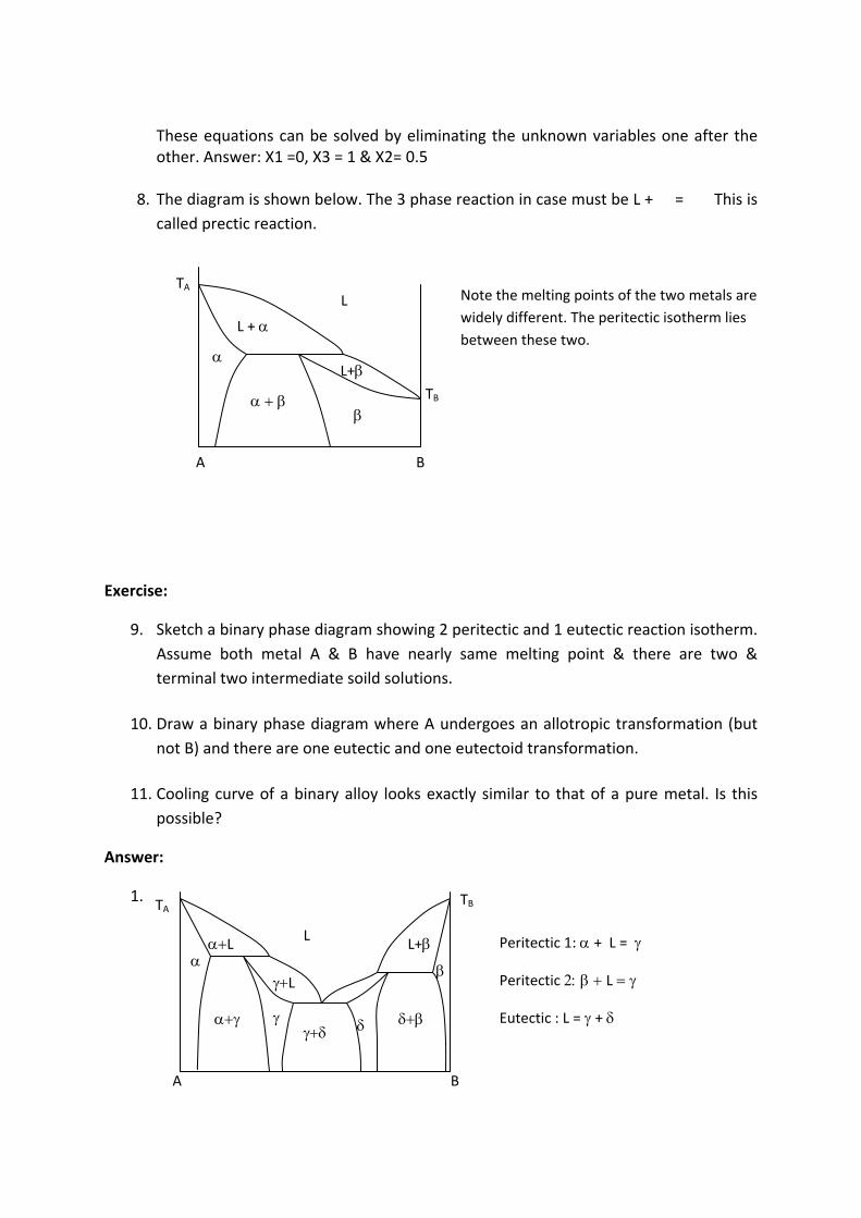
8. Draw the phase diagram for a binary alloy system having following features. Melting
point of the two metals (A & B) are widely different. These are partially soluble in
each other. There is one three phase reaction isotherm at a temperature higher than
the melting point of B but lower than that of A. Write down the equation
representing the 3 phase reaction. What is it commonly known as?
Answer:
4. The process of solidification at 779⁰C can be represented as L = �����. This involves
equlibrium between 3 phases. Such a system is known as eutectic. The phase
diagram is as follows:
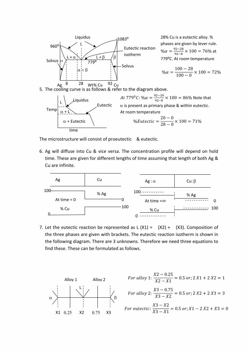
5. The cooling curve is as follows & refer to the diagram above.
The microstructure will consist of proeutectic � & eutectic. 6. Ag will diffuse into Cu & vice versa. The concentration profile will depend on hold
time. These are given for different lengths of time assuming that length of both Ag &
Cu are infinite.
7. Let the eutectic reaction be represented as L (X1) = � (X2) + � (X3). Composition of
the three phases are given with brackets. The eutectic reaction isotherm is shown in
the following diagram. There are 3 unknowns. Therefore we need three equations to
find these. These can be formulated as follows.
Liquidus Eutectic
+ Eutectic
+ L
L
Temp
time
%20 028 0
100 71%
779 : % 100 86% Note that
is present as primary phase & within eutectic.
At room temperature
%100 28100 0
100 72%
28% Cu is a eutectic alloy. %
phases are given by lever rule.
% 100 76% at
779⁰C. At room temperature 779⁰
Liquidus
28 8 92
1083⁰
960⁰
L
L + L +
Ag Cu Wt% Cu
Solvus Solvus
Eutectic reaction
isotherm
Ag Cu
% Ag 100
0
% Cu 0
100
At time = 0
Ag : Cu:
% Ag 100
0
% Cu
0
100
At time =∞
X1 X2 X3
L
Alloy 1 Alloy 2 1:2 0.252 1
0.5 ; 2 1 2 2 1
2:3 0.753 2
0.5 ; 2 2 2 3 3
:3 23 1
0.5 ; 1 2 2 3 0
These equations can be solved by eliminating the unknown variables one after the other. Answer: X1 =0, X3 = 1 & X2= 0.5
8. The diagram is shown below. The 3 phase reaction in case must be L + ��= ���This is
called prectic reaction.
Exercise:
9. Sketch a binary phase diagram showing 2 peritectic and 1 eutectic reaction isotherm.
Assume both metal A & B have nearly same melting point & there are two &
terminal two intermediate soild solutions.
10. Draw a binary phase diagram where A undergoes an allotropic transformation (but
not B) and there are one eutectic and one eutectoid transformation.
11. Cooling curve of a binary alloy looks exactly similar to that of a pure metal. Is this
possible?
Answer:
1.
L
L +
TA
A B
TB
Note the melting points of the two metals are
widely different. The peritectic isotherm lies
between these two.
L+
L
L L+
L
A B
TA TB
Peritectic 1: + L =
PeritecticL
Eutectic : L = +
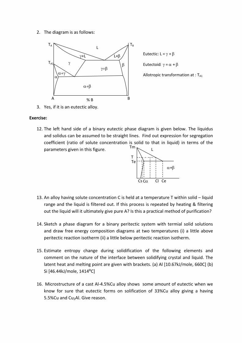
2. The diagram is as follows:
3. Yes, if it is an eutectic alloy.
Exercise:
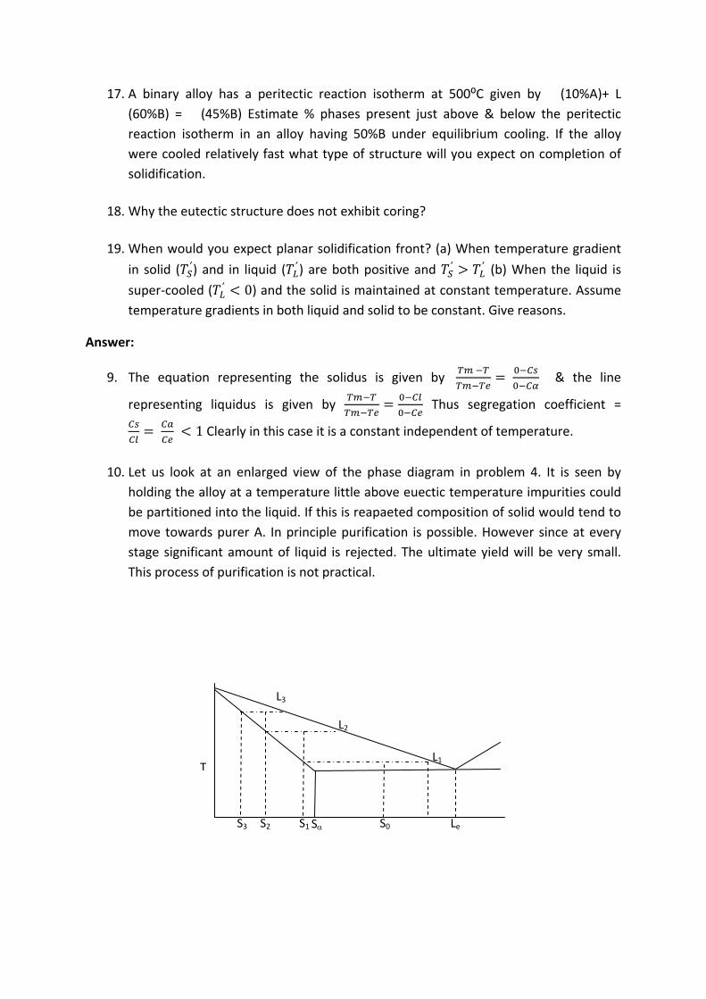
12. The left hand side of a binary eutectic phase diagram is given below. The liquidus
and solidus can be assumed to be straight lines. Find out expression for segregation
coefficient (ratio of solute concentration is solid to that in liquid) in terms of the
parameters given in this figure.
13. An alloy having solute concentration C is held at a temperature T within solid – liquid
range and the liquid is filtered out. If this process is repeated by heating & filtering
out the liquid will it ultimately give pure A? Is this a practical method of purification?
14. Sketch a phase diagram for a binary peritectic system with termial solid solutions
and draw free energy composition diagrams at two temperatures (i) a little above
peritectic reaction isotherm (ii) a little below peritectic reaction isotherm.
15. Estimate entropy change during solidification of the following elements and
comment on the nature of the interface between solidifying crystal and liquid. The
latent heat and melting point are given with brackets. (a) Al [10.67kJ/mole, 660C] (b)
Si [46.44kJ/mole, 1414⁰C]
16. Microstructure of a cast Al‐4.5%Cu alloy shows some amount of eutectic when we
know for sure that eutectic forms on solification of 33%Cu alloy giving a having
5.5%Cu and Cu2Al. Give reason.
L
A B % B
TA TB
+L L+ TA1
Eutectic: L = +
Eutectoid = +
Allotropic transformation at : TA1
Tm
Te
L
+
Ce C Cl
T
Cs
17. A binary alloy has a peritectic reaction isotherm at 500⁰C given by � (10%A)+ L
(60%B) = � (45%B) Estimate % phases present just above & below the peritectic
reaction isotherm in an alloy having 50%B under equilibrium cooling. If the alloy
were cooled relatively fast what type of structure will you expect on completion of
solidification.
18. Why the eutectic structure does not exhibit coring?
19. When would you expect planar solidification front? (a) When temperature gradient
in solid ( ′ ) and in liquid ( ′ ) are both positive and ′ ′ (b) When the liquid is
super‐cooled ( ′ 0) and the solid is maintained at constant temperature. Assume
temperature gradients in both liquid and solid to be constant. Give reasons.
Answer:
9. The equation representing the solidus is given by & the line
representing liquidus is given by Thus segregation coefficient =
1 Clearly in this case it is a constant independent of temperature.
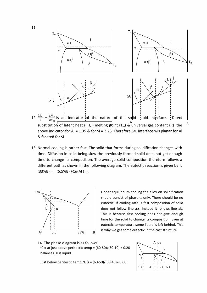
10. Let us look at an enlarged view of the phase diagram in problem 4. It is seen by
holding the alloy at a temperature little above euectic temperature impurities could
be partitioned into the liquid. If this is reapaeted composition of solid would tend to
move towards purer A. In principle purification is possible. However since at every
stage significant amount of liquid is rejected. The ultimate yield will be very small.
This process of purification is not practical.
S0 Le S
L1
S1
L2
L3
S2 S3
T
11.
12. ∆ ∆ is an indicator of the nature of the solid liquid interface. Direct
substitution of latent heat (�Hm) melting point (Tm) & universal gas contant (R) the
above indicator for Al = 1.35 & for Si = 3.26. Therefore S/L interface wis planar for Al
& faceted for Si.
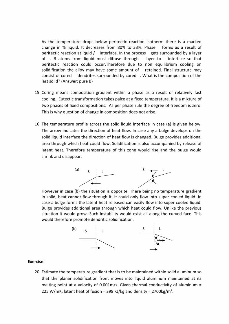
13. Normal cooling is rather fast. The solid that forms during solidification changes with
time. Diffusion in solid being slow the previously formed solid does not get enough
time to change its composition. The average solid composition therefore follows a
different path as shown in the following diagram. The eutectic reaction is given by L
(33%B) = � (5.5%B) +Cu2Al (�).
14. The phase diagram is as follows:
5.5 33% Al
Tm a
b
Under equilibrium cooling the alloy on solidification
should consist of phase only. There should be no eutectic. If cooling rate is fast composition of solid
does not follow line a. Instead it follows line ab. This is because fast cooling does not give enough
time for the solid to change its composition. Even at
eutectic temperature some liquid is left behind. This
is why we get some eutectic in the cast structure.
10 45 50 60
L
Alloy
% at just above peritectic temp = (60‐50)/(60‐10) = 0.20
balance 0.8 is liquid.
Just below peritectic temp: % = (60‐50)/(60‐45)= 0.66
+L
+
TA
G
A
L L
L+
+L
+L
+
TA
TB TB
G
L
A B B
L
As the temperature drops below peritectic reaction isotherm there is a marked change in % liquid. It decreases from 80% to 33%. Phase�� forms as a result of peritectic reaction at lquid / � interface. In the process � gets surrounded by a layer of��. B atoms from liquid must diffuse through � layer to � interface so that peritectic reaction could occur.Therefore due to non equilibrium cooling on solidification the alloy may have some amount of � retained. Final structure may consist of cored�� dendrites surrounded by cored �. What is the composition of the last solid? (Answer: pure B)
15. Coring means composition gradient within a phase as a result of relatively fast
cooling. Eutectic transformation takes palce at a fixed temperature. It is a mixture of
two phases of fixed compositions. As per phase rule the degree of freedom is zero.
This is why question of change in composition does not arise.
16. The temperature profile across the solid liquid interface in case (a) is given below.
The arrow indicates the direction of heat flow. In case any a bulge develops on the
solid liquid interface the direction of heat flow is changed. Bulge provides additional
area through which heat could flow. Solidification is also accompanied by release of
latent heat. Therefore temperature of this zone would rise and the bulge would
shrink and disappear.
However in case (b) the situation is opposite. There being no temperature gradient in solid, heat cannot flow through it. It could only flow into super cooled liquid. In case a bulge forms the latent heat released can easily flow into super cooled liquid. Bulge provides additional area through which heat could flow. Unlike the previous situation it would grow. Such instability would exist all along the curved face. This would therefore promote dendritic solidification.
Exercise:
20. Estimate the temperature gradient that is to be maintained within solid aluminum so
that the planar solidification front moves into liquid aluminum maintained at its
melting point at a velocity of 0.001m/s. Given thermal conductivity of aluminum =
225 W/mK, latent heat of fusion = 398 KJ/kg and density = 2700kg/m3.
S L S L (a)
S LS L(b)
21. What is partition coefficient? Derive Scheil equation for solidification of binary
alloys. State the assumptions made during its derivation. What is the composition of
the last solid that forms during solidification of a terminal solid solution of a binary
eutectic system?
22. Use the equations derived in the previous question to plot how the compositions at
the solid liquid interface keep changing as it moves while an Ag 5% Cu alloy is
directionally solidified. Ag‐Cu binary phase diagram has a eutectic reaction isotherm
at 779⁰C where an alloy containing 28.1%Cu solidifies as a mixture of � having
8.8%Cu and � having 92%Cu. The melting point of Ag is 960⁰C. The solidus and
liquidus lines may be assumed to be straight lines. What is the amount of eutectic in
the final structure?
23. What is constitutional super‐cooling? When does this take place?
24. Derive an expression for solute concentration just ahead of a planar solidification
front moving a constant velocity in a binary isomorphous alloy in absence of any
convection current in liquid and diffusion in solid.
Answer:
17. Heat balance per unit area across a planar solidification front is given by ′
′ where K is thermal conductivity. T’ denotes temperature gradient. Suffix
S & L represent solid & liquid respectively. Lv is latent heat of fusion / unit volume
and V is velocity of the planar front. Since the temperature of liquid aluminum is
constant ′ 0and thus ′
∴ ′ 0.001 4776 /
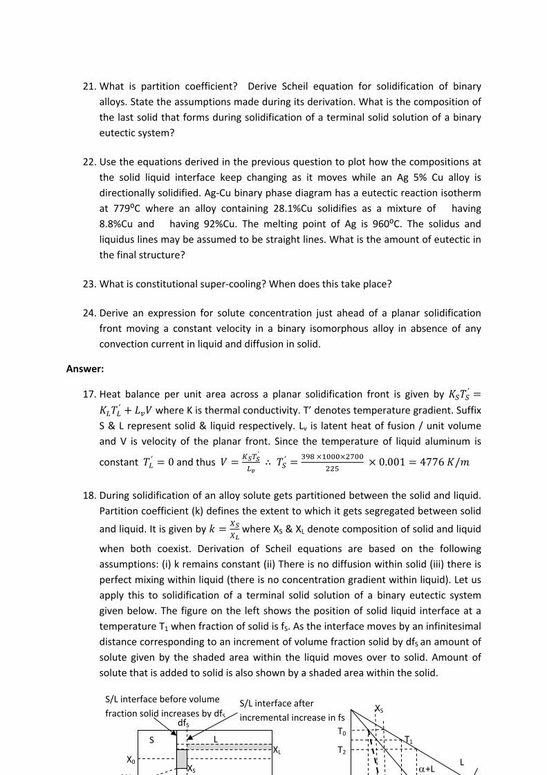
18. During solidification of an alloy solute gets partitioned between the solid and liquid.
Partition coefficient (k) defines the extent to which it gets segregated between solid
and liquid. It is given by where XS & XL denote composition of solid and liquid
when both coexist. Derivation of Scheil equations are based on the following
assumptions: (i) k remains constant (ii) There is no diffusion within solid (iii) there is
perfect mixing within liquid (there is no concentration gradient within liquid). Let us
apply this to solidification of a terminal solid solution of a binary eutectic system
given below. The figure on the left shows the position of solid liquid interface at a
temperature T1 when fraction of solid is fS. As the interface moves by an infinitesimal
distance corresponding to an increment of volume fraction solid by dfS an amount of
solute given by the shaded area within the liquid moves over to solid. Amount of
solute that is added to solid is also shown by a shaded area within the solid.
XS
T0
T2 T1
L +L
kX
X0 XS
XL S L
dfS
S/L interface before volume
fraction solid increases by dfS S/L interface after
incremental increase in fs

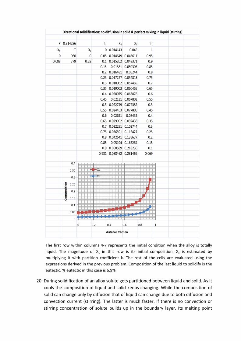
19. The phase diagram is shown in the following sketch. The results are given in an Excel sheet.
Apply conservation of solute. Equate the filled in area: 1
Note that . The final expression in obtained by integration
∴ 1 1 . Substitute initial condition: 0;
to evaluate the constant C. This is given by .Thus 1
1 .These two give the amount of solid and liquid like
lever rule in case of equilibrium solidification. These are known as Scheil equation.
Note that when XL approaches eutectic composition (XE) still there will be some liquid
left. This is given by: . The last solid that forms has the same
composition as that of the eutectic.
Note that the entries in first 3 columns give %
solute in both solid and liquid at melting point and
eutectic temperature. Partition coefficient k is
estimated from these entries. The next 3 columns
give fraction solid and solute concentrations in
solid and liquid. 1
0 28
L
960
749
% Cu
k 0.314286 fs XS XL fL
XS T XL 0 0.014143 0.045 1
0 960 0 0.05 0.014649 0.046611 0.95
0.088 779 0.28 0.1 0.015202 0.048371 0.9
0.15 0.01581 0.050305 0.85
0.2 0.016481 0.05244 0.8
0.25 0.017227 0.054813 0.75
0.3 0.018062 0.057469 0.7
0.35 0.019003 0.060465 0.65
0.4 0.020075 0.063876 0.6
0.45 0.02131 0.067803 0.55
0.5 0.022749 0.072382 0.5
0.55 0.024453 0.077805 0.45
0.6 0.02651 0.08435 0.4
0.65 0.029052 0.092438 0.35
0.7 0.032291 0.102744 0.3
0.75 0.036591 0.116427 0.25
0.8 0.042641 0.135677 0.2
0.85 0.05194 0.165264 0.15
0.9 0.068589 0.218236 0.1
0.931 0.088462 0.281469 0.069
Directional solidification: no diffusion in solid & perfect mixing in liquid (stirring)
0
0.05
0.1
0.15
0.2
0.25
0.3
0.35
0.4
0 0.2 0.4 0.6 0.8 1
Composition
distance fraction
XL
XS
The first row within columns 4‐7 represents the initial condition when the alloy is totally
liquid. The magnitude of XL in this row is its initial composition. XS is estimated by
multiplying it with partition coefficient k. The rest of the cells are evaluated using the
expressions derived in the previous problem. Composition of the last liquid to solidify is the
eutectic. % eutectic in this case is 6.9%
20. During solidification of an alloy solute gets partitioned between liquid and solid. As it
cools the composition of liquid and solid keeps changing. While the composition of
solid can change only by diffusion that of liquid can change due to both diffusion and
convection current (stirring). The latter is much faster. If there is no convection or
stirring concentration of solute builds up in the boundary layer. Its melting point

becomes significantly lower than that of the liquid away from the interface. If the
temperature gradient beyond the solid liquid interface is less than a critical value
constitutional super cooling occurs. This promotes solidification. If the gradient is
more than the critical value the solid liquid interface remains planar.
21. The following sketch shows a part of the phase diagram indicating the temperature
range over which solidification takes place in an alloy having a given composition
(X0). Here it takes place between T1 and T3. T2 is an intermediate temperature.
Composition of solid & liquid at the interface within this range is given by the solidus
and the liquidus. If partition coefficient is k composition of the first solid to form is
kX0. Subsequent solid would have higher solute content. The composition profile as a
function of the distance from the mold face is also shown in the next sketch. As the
planar front moves the liquid too at the interface will become richer in solute.
Therefore mass transfer within the liquid due to diffusion will keep increasing. This
would continue until the temperature reaches T3. At this stage the composition of
the liquid at the interface would be X0/k, whereas that of the solid should be X0.
Hereafter the composition of the liquid and solid would not change even if the front
moves. Velocity (v) of the front would be determined by the rate at which solute
would diffuse within the liquid. Since the concentration of solute would not change
hereafter the velocity of the front should remain constant. This stage, called steady
state would continue until the width of the remaining liquid becomes too small to
maintain its steady state composition. In such a situation the final transient stage
begins. The concentration starts building up. In case the alloy is a terminal solid
solution of a eutectic system the last liquid to solidify would be eutectic whereas in
case of an isomorphous system it would be pure B. During steady state the growth of
solid layer needs to dispose of an additional amount of solute given by . This has to diffuse through the stagnant liquid. The rate at which the solute would
diffuse is given by where D is diffusivity and x is the distance from the
solidification front. The concentration of solute ahead of the interface could
therefore be evaluated by equating these two.
Constant of integration is determined from initial condition that at 0,
/ . Thus we get 1
;
% B XL XS
T2
X0
T1
T3
kX0 X0/k
X0 kX0
L S
XS
XL X0 kX0
L S X0/k
X0 kX0
L S XS XL
(a) Initial stage (b) Steady state
(c) Final stage
Exercise:
1. FCC is a more close packed structure yet solubility of carbon in austenite which is
FCC is higher than that in ferrite which is BCC. Why it is so?
2. Sketch the microstructure of 0.2% C steel. Calculate %Pearlite % cementite, %
proeutectoid ferrite and % total ferrite.
3. Estimate the ratio of the widths of ferrite and cementite plates in lamellar pearlite.
4. Sketch the temperarture – time diagram during the heating cycle of a 0.8% C steel.
Use standard Fe‐Fe3C phase diagram.
5. Estimate %Cm in Ledeburite just below eutectic and just above eutectoid
temeratures. What is its structure at room temperature?
Answer:
1. There are 2 types of interstitial sites octahedral & tetrahedral. In FCC the former is
significantly larger than the latter. Whereas in BCC these are nearly same. The total
open space is shared by more number of sites. Therfore interstitial gap in BCC is
much smaller than that of FCC. This is why carbon which occupies interstitial site has
higher solubility in austenite (FCC).
2. The stucture would consist of proeutectoid ferrite and pearlite. Assume solubility of
carbon in ferrite is negligible. Refer to phase diagram to get % Pearlite in 0.2%
carbon steel = .
.100 25 Balance 75% is proeutectoid ferrite. % Cementite =
.
.100 3% and total ferrite = 97%.
3. Assume density of ferrite and cementite to be same (Note that in reality density of
cementite is a little higher than that of ferrite). % ferrite in pearlite = . .
.
100 88. Balance 12% is cementite. Therefore the ratio of the widths of the two =
12/88. This is approximately equal to 1:7.
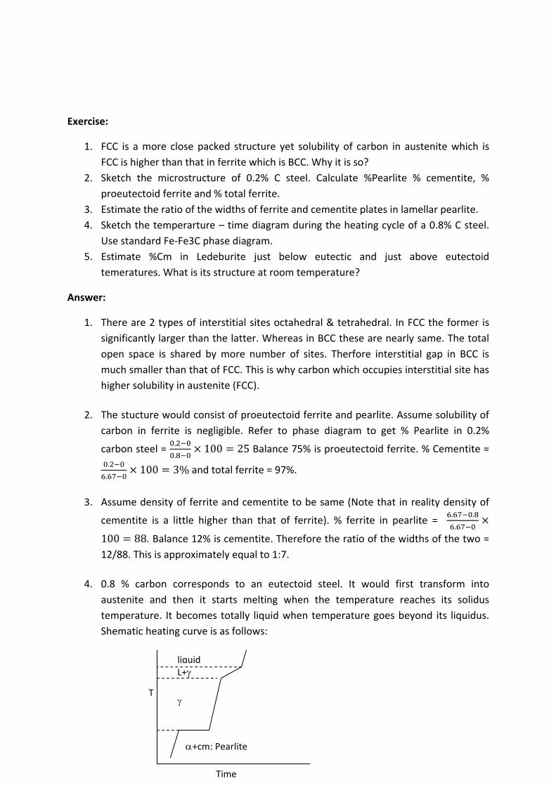
4. 0.8 % carbon corresponds to an eutectoid steel. It would first transform into
austenite and then it starts melting when the temperature reaches its solidus
temperature. It becomes totally liquid when temperature goes beyond its liquidus.
Shematic heating curve is as follows:
T
Time
liquid L+
+cm: Pearlite
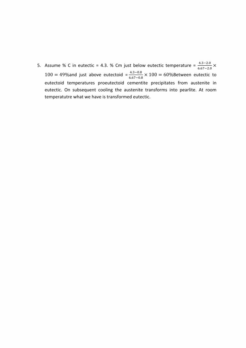
5. Assume % C in eutectic = 4.3. % Cm just below eutectic temperature = . .
. .
100 49%and just above eutectoid = . .
. .100 60%Between eutectic to
eutectoid temperatures proeutectoid cementite precipitates from austenite in
eutectic. On subsequent cooling the austenite transforms into pearlite. At room
temperatutre what we have is transformed eutectic.
Iron – Cementite Meta‐stable Binary Phase diagram
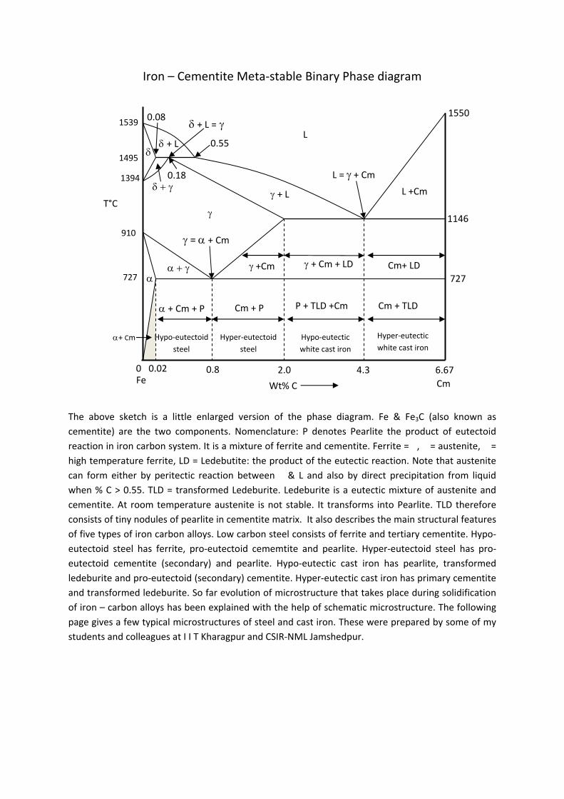
The above sketch is a little enlarged version of the phase diagram. Fe & Fe3C (also known as
cementite) are the two components. Nomenclature: P denotes Pearlite the product of eutectoid
reaction in iron carbon system. It is a mixture of ferrite and cementite. Ferrite = �, � = austenite, � =
high temperature ferrite, LD = Ledebutite: the product of the eutectic reaction. Note that austenite
can form either by peritectic reaction between � & L and also by direct precipitation from liquid
when % C > 0.55. TLD = transformed Ledeburite. Ledeburite is a eutectic mixture of austenite and
cementite. At room temperature austenite is not stable. It transforms into Pearlite. TLD therefore
consists of tiny nodules of pearlite in cementite matrix. It also describes the main structural features
of five types of iron carbon alloys. Low carbon steel consists of ferrite and tertiary cementite. Hypo‐
eutectoid steel has ferrite, pro‐eutectoid cememtite and pearlite. Hyper‐eutectoid steel has pro‐
eutectoid cementite (secondary) and pearlite. Hypo‐eutectic cast iron has pearlite, transformed
ledeburite and pro‐eutectoid (secondary) cementite. Hyper‐eutectic cast iron has primary cementite
and transformed ledeburite. So far evolution of microstructure that takes place during solidification
of iron – carbon alloys has been explained with the help of schematic microstructure. The following
page gives a few typical microstructures of steel and cast iron. These were prepared by some of my
students and colleagues at I I T Kharagpur and CSIR‐NML Jamshedpur.
T°C
Wt% C
0.8 2.00.02 0
1539
1495
1394
727
910
L
+ L
+ L
+ Cm + P
Cm+ LD
1550
4.3 6.67
L +Cm
+Cm
Cm + TLD
+ Cm + LD
P + TLD +Cm Cm + P
1146
727
Cm Fe
Hyper‐eutectic
white cast iron Hypo‐eutectic
white cast iron
Hyper‐eutectoid
steel
Hypo‐eutectoid
steel
+ Cm
0.18
0.55
0.08
L = + Cm
= + Cm
+ L =

Typical microstructures of steel and cast iron
Fig A1: Microstructure of 0.15% carbon steel consisting of ferrite (bright) and pearlite (dark). Lamellar feature pearlite is not visible. (Curtsey G Das CSIR‐NML Jamshedpur)
Fig A2: Microstructure of medium carbon steel consisting of ferrite (bright) and pearlite (dark). Amount of pearlite increases with % carbon. (Curtsey G Das CSIR‐NML Jamshedpur).
Fig A3: Microstructure of a near eutectoid steel having a little pro‐eutectoid cementite in a matrix of pearlite. In some of regions finer details of pearlitic (lamellar) structure is visible.
Fig A4: SEM image of 0.84% C steel having nearly 100% pearlite. Lamellar feature is clearly visible. The dark region is pro‐eutectoid cementite. (Curtsey G Das CSIR‐NML Jamshedpur)
Fig A5: Microstructure of hyper‐eutectic white cast iron showing primary carbides (cm). The rest of the region consists of a mixture of pearlite and cementite or transformed eutectic (ledeburite).
Fig A6: Microstructure of grey cast iron having graphite flakes in a matrix consisting of mostly ferrite and some amount of pearlite. (Curtsey G Das CSIR‐NML Jamshedpur)

Exercise:
1. If an eutectoid steel is kept at 700⁰C what change do you expect? 2. What is the limitation of phase diagram? 3. If a piece of steel having 0.8 % carbon has martensitic stucture can it be converted to
fully pearlite structure by holding it at 700⁰ C? 4. Suggest a method of getting a mixture of Pearlite, Bainite & Martensite in an
eutectoid steel. 5. Which microstructure in eutectoid steel has maximum hardenss? Give reason.
Answer:
6. Lamellar structure is unstable as it has large surface area. Initially the cementite plates would break down in to globular structure. Size of the globule will grow with time. Cementite is also metastable on prolonged thermal exposure it breaks down in to ferrite and graphite.
7. Phase diagram does not show the effect of cooling rate. It gives the expected phases in an alloy at a given temperature under equilibrium condition.
8. No. To get pearlitic structure it must be heated back to austenite state then cooled slowly.
9. This is possible through two step isothermal transformation in Pearlitic & Bainitic region followed by queching. The cooling scheme is shown below. Note that no transformation takes place during quenching (fast cooling: the virtical step in cooling curve) if temperature is above Ms.
10. Martenstic structure has the maximum hardness. This is because of the presence of carbon atoms in the interstices is far in excess of its normal solubility in ferrite lattice. This results in tetragonal lattice distortion. This makes dislocation movement very difficult. This in conjuction with extremely fine microstructure account for the high hardness of Martensite.
T
t
P
B
+P
+M
Ms
Mf
Exercise:
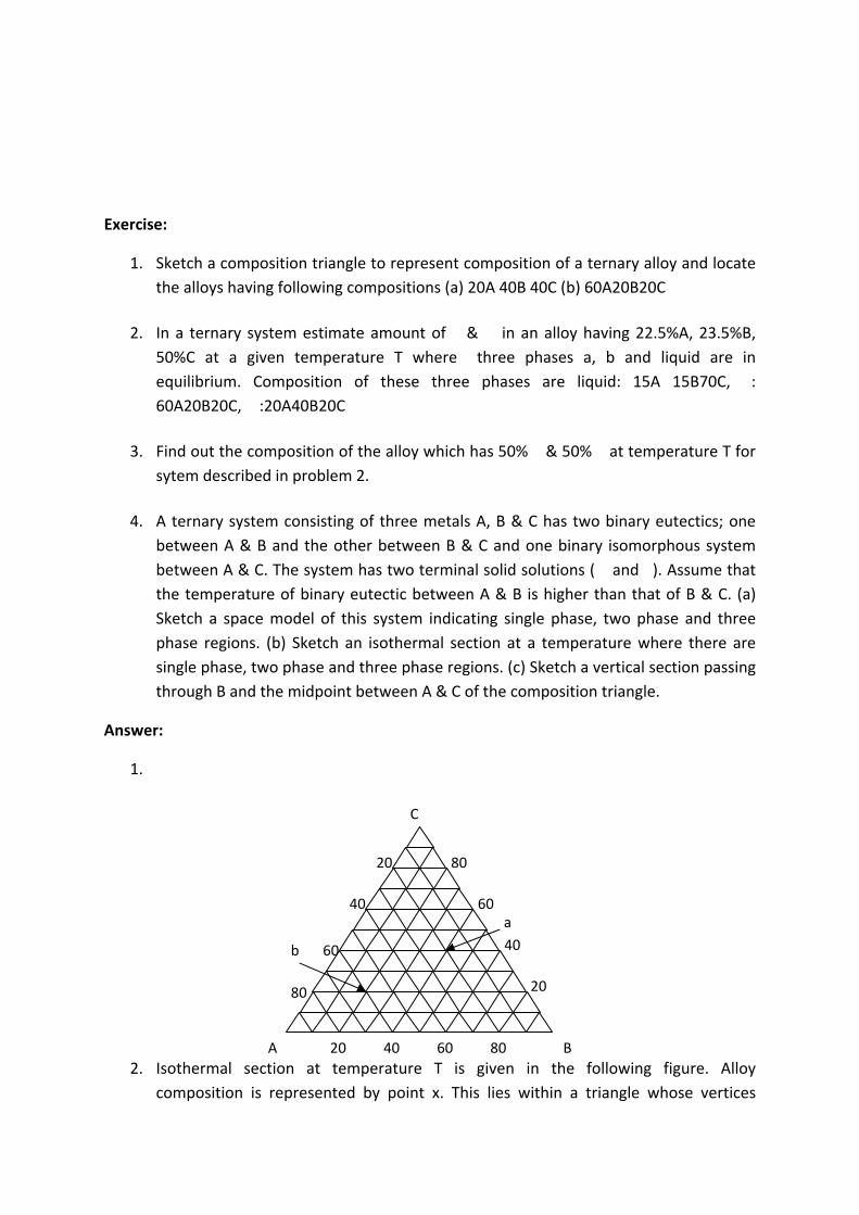
1. Sketch a composition triangle to represent composition of a ternary alloy and locate
the alloys having following compositions (a) 20A 40B 40C (b) 60A20B20C
2. In a ternary system estimate amount of � &�� in an alloy having 22.5%A, 23.5%B,
50%C at a given temperature T where three phases a, b and liquid are in
equilibrium. Composition of these three phases are liquid: 15A 15B70C, �:
60A20B20C,��:20A40B20C
3. Find out the composition of the alloy which has 50% � & 50% � at temperature T for
sytem described in problem 2.
4. A ternary system consisting of three metals A, B & C has two binary eutectics; one
between A & B and the other between B & C and one binary isomorphous system
between A & C. The system has two terminal solid solutions (��and �). Assume that
the temperature of binary eutectic between A & B is higher than that of B & C. (a)
Sketch a space model of this system indicating single phase, two phase and three
phase regions. (b) Sketch an isothermal section at a temperature where there are
single phase, two phase and three phase regions. (c) Sketch a vertical section passing
through B and the midpoint between A & C of the composition triangle.
Answer:
1.
2. Isothermal section at temperature T is given in the following figure. Alloy
composition is represented by point x. This lies within a triangle whose vertices
A B
C
20 40 60 80
20
40
60
8020
40
60
80
b
a
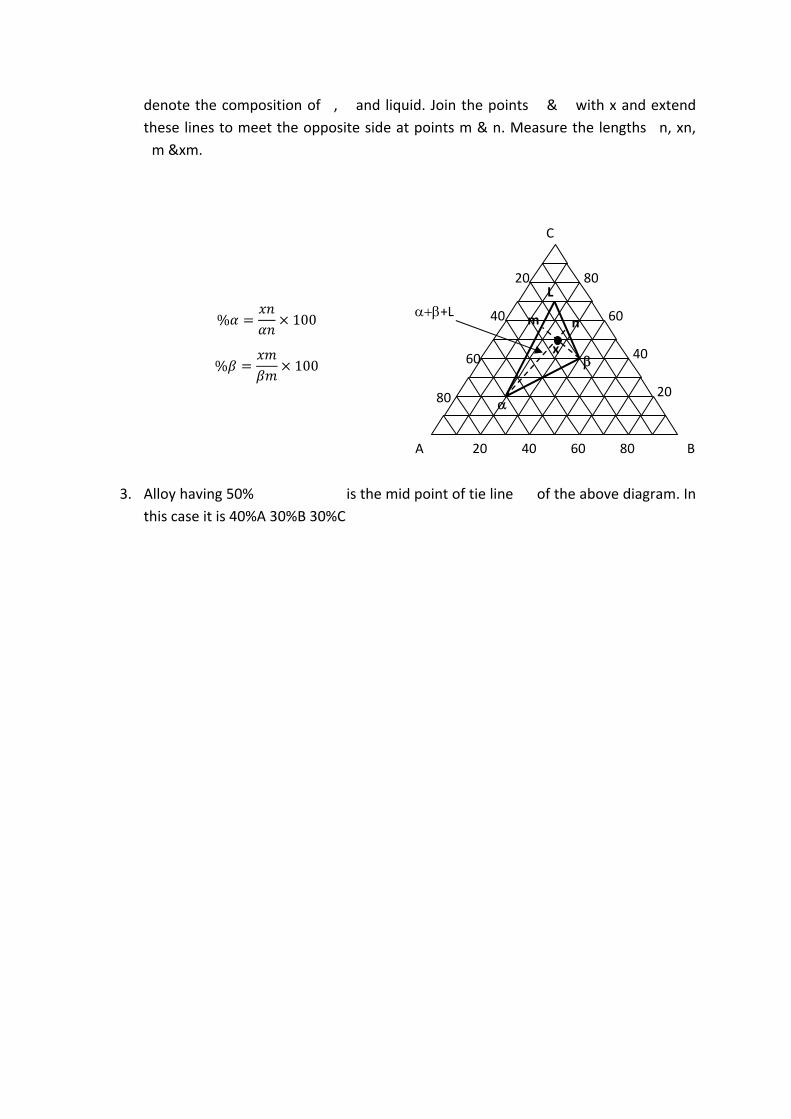
denote the composition of �, � and liquid. Join the points � & � with x and extend
these lines to meet the opposite side at points m & n. Measure the lengths �n, xn,
�m &xm.
3. Alloy having 50%����������� is the mid point of tie line �� of the above diagram. In
this case it is 40%A 30%B 30%C
A B
C
20 40 60 80
20
40
60
80 20
40
60
80
+L
L
x
m n % 100
% 100
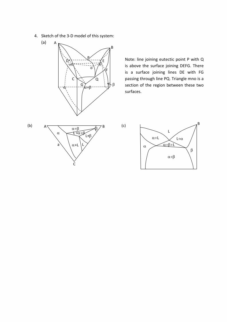
4. Sketch of the 3‐D model of this system:
(a)
(b) (c)
L
B
L LL
A B
C
L
L+
+L
L +
a
A B
C
D E
F
G
P
Q
o m n
Note: line joining eutectic point P with Q
is above the surface joining DEFG. There
is a surface joining lines DE with FG
passing through line PQ. Triangle mno is a
section of the region between these two
surfaces.
Exercise:
1. List a few advantages & limitation of hot working.
2. List a few advantages and limitations of cold working.
3. Estimate energy required to extrude 250mm diameter billet of aluminium to 25mm
diameter rod. Given flow stress of aluminium = 10MPa and therefore find out the
amount of force needed. Process efficency = 70%. Neglet work hardening.
4. If the maximum strain per pass in a wire drwing operation is 0.65 how many drawing
passes will be rquired to draw wire of 0.25mm dia from 5mm wire rod?
Answers:
1. Advatages: Hotworking is done above recrystallisation temperature where flow
stress is very low therefore it is possible to give large deformation with minimum
effort ( energy rquired is less). No futher heat treatment is required. Product is in
annealed / normalised state. Limitation: Metal tends to oxidise. Scaling leads to loss
of material. Tool life is shortened because of abrasive scale, high temperature and
lack of lubrication. Poor surface finish & difficulty in precise guage control. It is
necessary to pickle hot rolled sheets before cold rolling to remove oxide scale.
2. Advantages: Good surface finish & precise guage control. Gives higher strength.
Limitation: needs intermediate annealing because of work hardening, deformation /
pass is limited by flow stress which increases with deformation, more energy
intensive, needs more powerful equipment, Makes the material anisotropic.
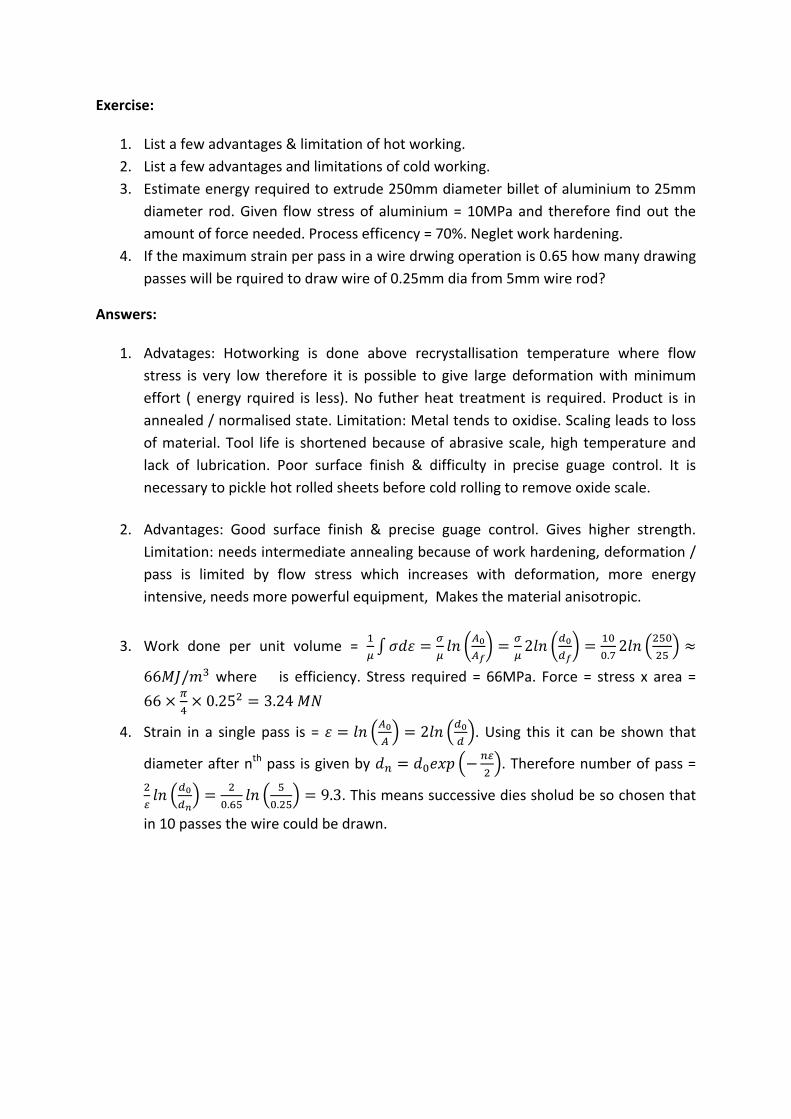
3. Work done per unit volume = 2.2
66 / where�� is efficiency. Stress required = 66MPa. Force = stress x area =
66 0.25 3.24
4. Strain in a single pass is = 2 . Using this it can be shown that
diameter after nth pass is given by . Therefore number of pass =
. .9.3. This means successive dies sholud be so chosen that
in 10 passes the wire could be drawn.
Exercise:
5. While designing rolling process discuss whether large reduction in a single pass is
prefrerable to smaller reductions in successive passes?
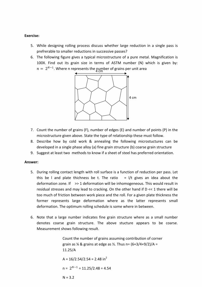
6. The following figure gives a typical microstructure of a pure metal. Magnification is
100X. Find out its grain size in terms of ASTM number (N) which is given by:
2 . Where n represents the number of grains per unit area
7. Count the number of grains (F), number of edges (E) and number of points (P) in the
microstructure given above. State the type of relationship these must follow.
8. Describe how by cold work & annealing the following microstuctures can be
developed in a single phase alloy (a) fine grain structure (b) coarse grain structure
9. Suggest at least two methods to know if a sheet of steel has preferred orientation.
Answer:
5. During rolling contact length with roll surface is a function of reduction per pass. Let
this be l and plate thichness be t. The ratio�� = l/t gives an idea about the
deformation zone. If � >> 1 deformation will be inhomogeneous. This would result in
residual stresses and may lead to cracking. On the other hand if D << 1 there will be
too much of friction between work piece and the roll. For a given plate thickness the
former represents large deformation where as the latter represents small
deformation. The optimum rolling schedule is some where in between.
6. Note that a large number indicates fine grain structure where as a small number
denotes coarse grain structure. The above stucture appears to be coarse.
Measurement shows following result.
4 cm
4 cm
Count the number of grains assuming contribution of corner
grain as ¼ & grains at edge as ½. Thus n= (6+3/4+9/2)/A =
11.25/A
A = 16/2.54/2.54 = 2.48 in2
n = 2 = 11.25/2.48 = 4.54
N = 3.2
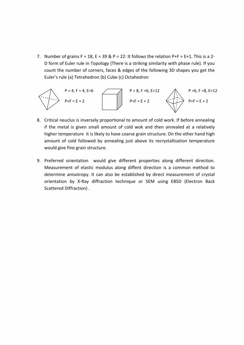
7. Number of grains F = 18, E = 39 & P = 22: It follows the relation P+F = E+1. This is a 2‐
D form of Euler rule in Topology (There is a striking similarity with phase rule). If you
count the number of corners, faces & edges of the following 3D shapes you get the
Euler’s rule (a) Tetrahedron (b) Cube (c) Octahedron
8. Critical neuclus is inversely proportional to amount of cold work. If before annealing
if the metal is given small amount of cold wok and then annealed at a relatively
higher temperature it is likely to have coarse grain structure. On the other hand high
amount of cold followed by annealing just above its recrystallisation temperature
would give fine grain structure.
9. Preferred orientation would give different properties along different direction.
Measurement of elastic modulus along diffent direction is a common method to
determine anisotropy. It can also be established by direct measurement of crystal
orientation by X‐Ray diffraction technique or SEM using EBSD (Electron Back
Scattered Diffraction) .
P = 4, F = 4, E=6
P+F = E + 2
P = 8, F =6, E=12
P+F = E + 2
P =6, F =8, E=12
P+F = E + 2
Exercise:
1. What types of alloys would respond to precipitation hardening?
2. Why Aluminium alloy rivets are strored in refigerator?
3. For a lens shaped�� nucleus formed at �� interface estimate the angle � if ��� = 500
and ��� = 600mJ/m2 and hence find out the shape factor of the precipitate.
4. Critical radii for both homogeneous and heterogeneous nucleation are the same yet
the latter is more likely to occur. Give reason.
5. A batch of age hadrenable alloy has been overagred by mistake. Is there any way to
slavage these?
Answers:
1. Alloys which at room temperture has at least two phases and on heating beyond a
temperature attains a single phase structure (solid) can respond to precipitation
hardening provided it satisfies the following conditions i) on queching precipitation
could be suppressed ii) on heating or aging precipitates that nucleates are cohent
with the matrix.
2. Alumunium alloy rivets are first solution treated to get supersaturated solid solution
so that they are soft and could be easily deformed durring rivetting. If these are not
stored at subzero temperature after solution treatment they would age and become
strong and relatively brittle. Therefore it would become unusable.
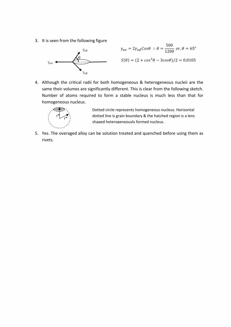
3. It is seen from the following figure
4. Although the critical radii for both homogeneous & heterogeneous nucleii are the
same their volumes are significantly different. This is clear from the following sketch.
Number of atoms required to form a stable nucleus is much less than that for
homogeneous nucleus.
5. Yes. The overaged alloy can be solution treated and quenched before using them as
rivets.
2 ∴5001200
, 65°
2 3 /2 0.0105
r* r*
Dotted circle represents homogeneous nucleus. Horizontal
dotted line is grain boundary & the hatched region is a lens
shaped heterogeneously formed nucleus.
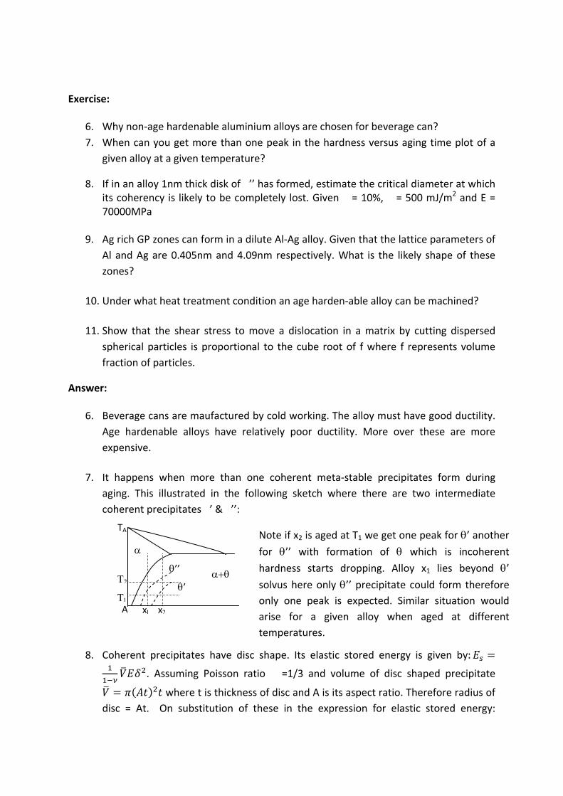
Exercise:
6. Why non‐age hardenable aluminium alloys are chosen for beverage can?
7. When can you get more than one peak in the hardness versus aging time plot of a
given alloy at a given temperature?
8. If in an alloy 1nm thick disk of �’’ has formed, estimate the critical diameter at which its coherency is likely to be completely lost. Given � = 10%, � = 500 mJ/m2 and E = 70000MPa
9. Ag rich GP zones can form in a dilute Al‐Ag alloy. Given that the lattice parameters of
Al and Ag are 0.405nm and 4.09nm respectively. What is the likely shape of these
zones?
10. Under what heat treatment condition an age harden‐able alloy can be machined?
11. Show that the shear stress to move a dislocation in a matrix by cutting dispersed
spherical particles is proportional to the cube root of f where f represents volume
fraction of particles.
Answer:
6. Beverage cans are maufactured by cold working. The alloy must have good ductility.
Age hardenable alloys have relatively poor ductility. More over these are more
expensive.
7. It happens when more than one coherent meta‐stable precipitates form during
aging. This illustrated in the following sketch where there are two intermediate
coherent precipitates �’ & �’’:
8. Coherent precipitates have disc shape. Its elastic stored energy is given by:
. Assuming Poisson ratio�� =1/3 and volume of disc shaped precipitate
where t is thickness of disc and A is its aspect ratio. Therefore radius of
disc = At. On substitution of these in the expression for elastic stored energy:
Note if x2 is aged at T1 we get one peak for ’ another for ’’ with formation of which is incoherent hardness starts dropping. Alloy x1 lies beyond ’ solvus here only ’’ precipitate could form therefore
only one peak is expected. Similar situation would
arise for a given alloy when aged at different
temperatures.
A
TA
’
’’
x x
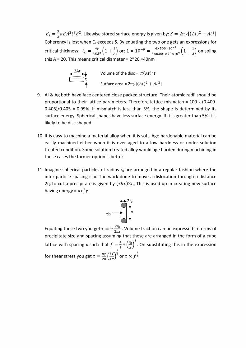
. Likewise stored surface energy is given by: 2
Coherency is lost when Es exceeds S. By equating the two one gets an expressions for
critical thickness: 1 or; 1 10.
1 on soling
this A = 20. This means critical diameter = 2*20 =40nm
9. Al & Ag both have face centered close packed structure. Their atomic radii should be
proportional to their lattice parameters. Therefore lattice mismatch = 100 x (0.409‐
0.405)/0.405 = 0.99%. If mismatch is less than 5%, the shape is determined by its
surface energy. Spherical shapes have less surface energy. If it is greater than 5% it is
likely to be disc shaped.
10. It is easy to machine a material alloy when it is soft. Age hardenable material can be
easily machined either when it is over aged to a low hardness or under solution
treated condition. Some solution treated alloy would age harden during machining in
those cases the former option is better.
11. Imagine spherical particles of radius r0 are arranged in a regular fashion where the
inter‐particle spacing is x. The work done to move a dislocation through a distance
2r0 to cut a precipitate is given by 2 This is used up in creating new surface
having energy = .
Equating these two you get . Volume fraction can be expressed in terms of
precipitate size and spacing assuming that these are arranged in the form of a cube
lattice with spacing x such that . On substituting this in the expression
for shear stress you get or ∝
b x
2r0
2At
t
Volume of the disc =
Surface area = 2
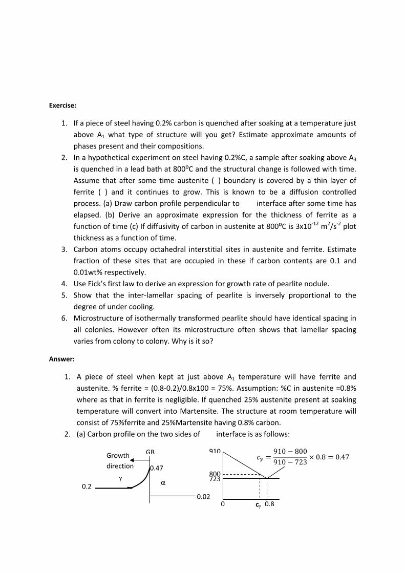
Exercise:
1. If a piece of steel having 0.2% carbon is quenched after soaking at a temperature just
above A1 what type of structure will you get? Estimate approximate amounts of
phases present and their compositions.
2. In a hypothetical experiment on steel having 0.2%C, a sample after soaking above A3
is quenched in a lead bath at 800⁰C and the structural change is followed with time.
Assume that after some time austenite (�) boundary is covered by a thin layer of
ferrite (�) and it continues to grow. This is known to be a diffusion controlled
process. (a) Draw carbon profile perpendicular to ��� interface after some time has
elapsed. (b) Derive an approximate expression for the thickness of ferrite as a
function of time (c) If diffusivity of carbon in austenite at 800⁰C is 3x10‐12 m2/s‐2 plot
thickness as a function of time.
3. Carbon atoms occupy octahedral interstitial sites in austenite and ferrite. Estimate
fraction of these sites that are occupied in these if carbon contents are 0.1 and
0.01wt% respectively.
4. Use Fick’s first law to derive an expression for growth rate of pearlite nodule.
5. Show that the inter‐lamellar spacing of pearlite is inversely proportional to the
degree of under cooling.
6. Microstructure of isothermally transformed pearlite should have identical spacing in
all colonies. However often its microstructure often shows that lamellar spacing
varies from colony to colony. Why is it so?
Answer:
1. A piece of steel when kept at just above A1 temperature will have ferrite and
austenite. % ferrite = (0.8‐0.2)/0.8x100 = 75%. Assumption: %C in austenite =0.8%
where as that in ferrite is negligible. If quenched 25% austenite present at soaking
temperature will convert into Martensite. The structure at room temperature will
consist of 75%ferrite and 25%Martensite having 0.8% carbon.
2. (a) Carbon profile on the two sides of ��� interface is as follows:
0.2
0.02
GBGrowth
direction
910
800723
0.80 c
910 800910 723
0.8 0.47 0.47

(b) To derive a simple relation we assume: densities of austenite and ferrite are the same.
Therefore wt % =vol %. Area of interface = 1. Carbon gradient in austenite is constant. This is
given by following sketch
From the above one gets: On substituting L :
On integration thickness of ferrite layer at any time t =
(c) 10. .
. . 2.33 10 or 1.53 10 Note that this
estimate is valid only for short time.
3. Number of octahedral site in austenite = 1 / atom of Fe. Atomic wt of carbon = 12 and Fe =
56. Atom fraction carbon in austenite = .
. ..
0.0047. In one unit cell
there are 4 Fe atoms and 4 interstitial sites. Fraction of these that are occupied = 0.0047.
This mean amongst 100 unit cell the number of carbon atom is approximately 2
(~400x0.0047).
Whereas in ferrite the number of such sites / Fe atom = 3. Atom fraction carbon .
0.00047. In one unit cell there are 2Fe atoms. Number of carbon atom =
0.00094. There are 6 sites / unit cell. Fraction of these that are occupied = 0.00094/12 =
7.8x10‐5. This means there is approximately one carbon atom in approximately 1000 unit
cells.
4. Super cooling is necessary for Pearlite to nucleate:
C0
C
C
x
L
austenite ferrite
Carbon gradient in = ∴ flux of carbon crossing the
interface in time dt to move this by dx =
This is equal to flux of carbon rejected by
as it grows by dx = . L is obtained by
equating the hatched area of the adjoining figure.
/2
x
T0
TE
%C
cm
Pearlite colony grows as carbon
diffuses from / interface to cm / interface. Flux of C / unit
area =
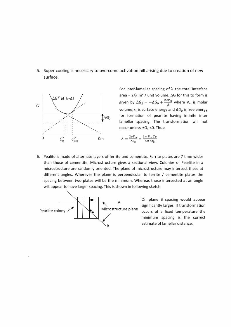
5. Super cooling is necessary to overcome activation hill arising due to creation of new
surface.
6. Pealite is made of alternate layers of ferrite and cementite. Ferrite plates are 7 time wider
than those of cementite. Microstructure gives a sectional view. Colonies of Pearlite in a
microstructure are randomly oriented. The plane of microstructure may intersect these at
different angles. Wherever the plane is perpendicular to ferrite / cementite plates the
spacing between two plates will be the minimum. Whereas those intersected at an angle
will appear to have larger spacing. This is shown in following sketch:
.
Pearlite colony Microstructure plane
A
B
On plane B spacing would appear
significantly larger. If transformation
occurs at a fixed temperature the
minimum spacing is the correct
estimate of lamellar distance.
G
G0
Cm
∆ at TE‐T
For inter‐lamellar spacing of the total interface area = 2/ m2 / unit volume. G for this to form is
given by ∆ ∆ where Vm is molar
volume, is surface energy and ∆ is free energy for formation of pearlite having infinite inter
lamellar spacing. The transformation will not
occur unless G <0. Thus:
∆ ∆ ∆
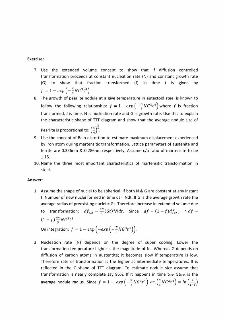
Exercise:
7. Use the extended volume concept to show that if diffusion controlled
transformation proceeds at constant nucleation rate (N) and constant growth rate
(G) to show that fraction transformed (f) in time t is given by
1
8. The growth of pearlite nodule at a give temperature in eutectoid steel is known to
follow the following relationship: 1 where f is fraction
transformed, t is time, N is nucleation rate and G is growth rate. Use this to explain
the characteristic shape of TTT diagram and show that the average nodule size of
Pearlite is proportional to: .
9. Use the concept of Bain distortion to estimate maximum displacement experienced
by iron atom during martensitic transformation. Lattice parameters of austenite and
ferrite are 0.356nm & 0.286nm respectively. Assume c/a ratio of martensite to be
1.15.
10. Name the three most important characteristics of martensitic transformation in
steel.
Answer:
1. Assume the shape of nuclei to be spherical. If both N & G are constant at any instant
t. Number of new nuclei formed in time dt = Ndt. If G is the average growth rate the
average radius of preexisting nuclei = Gt. Therefore increase in extended volume due
to transformation: . Since 1 ∴
1
On integration: 1 .
2. Nucleation rate (N) depends on the degree of super cooling. Lower the
transformation temperature higher is the magnitude of N. Whereas G depends on
diffusion of carbon atoms in austentite; it becomes slow if temperature is low.
Therefore rate of transformation is the higher at intermediate temperatures. It is
reflected in the C shape of TTT diagram. To estimate nodule size assume that
transformation is nearly complete say 95%. If it happens in time t0.95 Gt0.95 is the
average nodule radius. Since 1 ,
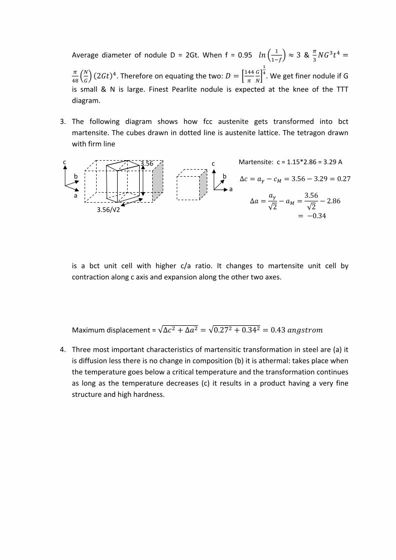
Average diameter of nodule D = 2Gt. When f = 0.95 3 &
2 . Therefore on equating the two: . We get finer nodule if G
is small & N is large. Finest Pearlite nodule is expected at the knee of the TTT
diagram.
3. The following diagram shows how fcc austenite gets transformed into bct
martensite. The cubes drawn in dotted line is austenite lattice. The tetragon drawn
with firm line
is a bct unit cell with higher c/a ratio. It changes to martensite unit cell by
contraction along c axis and expansion along the other two axes.
Maximum displacement = √∆ ∆ √0.27 0.34 0.43
4. Three most important characteristics of martensitic transformation in steel are (a) it
is diffusion less there is no change in composition (b) it is athermal: takes place when
the temperature goes below a critical temperature and the transformation continues
as long as the temperature decreases (c) it results in a product having a very fine
structure and high hardness.
a a
c c
b b
3.56
3.56/√2
∆ 3.56 3.29 0.27
∆√2
3.56
√22.86
0.34
Martensite: c = 1.15*2.86 = 3.29 A
Exercise:
11. Explain why bainite does not form during continuous cooling in plain carbon steel.
12. Why do not you have long carbide plates like Pearlite in Baintite?
13. Use the equation given in the lecture note for total free energy change for
nucleation of martensite and find out the expressions for critical nucleus size and
activation hill.
14. Use the above expressions to estimate critical nucleus size and activation hill if �Gv =
‐180MJ/m3, A = 3 GPa, � = 18 mJ/m2.
Answer:
1. Bainite is a low temperature eutectoid transformation. For it to form in steel it must
be cooled below a critical temperature. This corresponds to the knee of TTT diagram.
During continuous cooling once you avoid the knee unless you allow isothermal
holding Bainite cannot form as it needs longer hold time since the reaction is very
slow.
2. Bainite forms at low temperature where rate of carbon diffusion is very slow
although nucleation rate is high because of high degree of super cooling. You have a
situation where there are more nuclei and limited (short) diffusion distance over
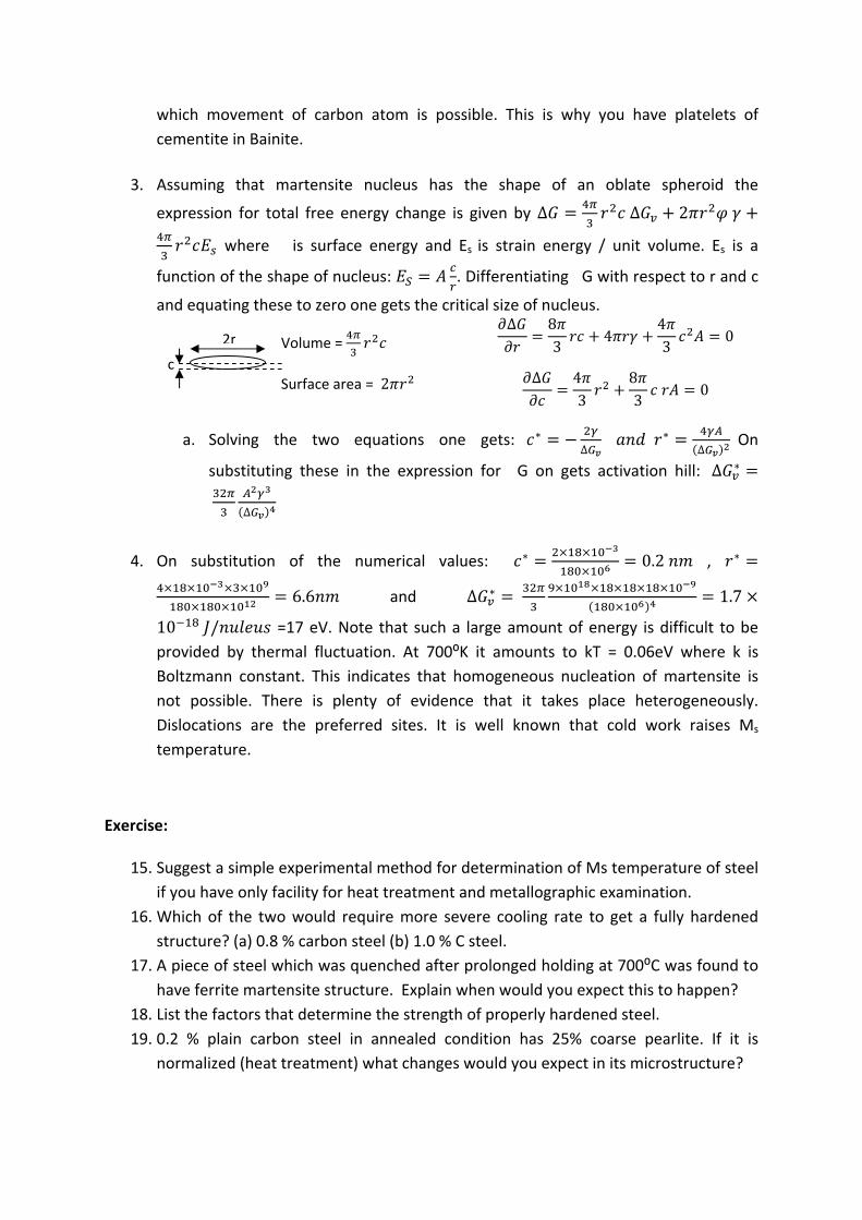
which movement of carbon atom is possible. This is why you have platelets of
cementite in Bainite.
3. Assuming that martensite nucleus has the shape of an oblate spheroid the
expression for total free energy change is given by ∆ ∆ 2
where � is surface energy and Es is strain energy / unit volume. Es is a
function of the shape of nucleus: . Differentiating �G with respect to r and c
and equating these to zero one gets the critical size of nucleus.
a. Solving the two equations one gets: ∗∆
∗∆
On
substituting these in the expression for �G on gets activation hill: ∆ ∗
∆
4. On substitution of the numerical values: ∗ 0.2 , ∗
6.6 and ∆ ∗ 1.7
10 / =17 eV. Note that such a large amount of energy is difficult to be
provided by thermal fluctuation. At 700⁰K it amounts to kT = 0.06eV where k is
Boltzmann constant. This indicates that homogeneous nucleation of martensite is
not possible. There is plenty of evidence that it takes place heterogeneously.
Dislocations are the preferred sites. It is well known that cold work raises Ms
temperature.
Exercise:
15. Suggest a simple experimental method for determination of Ms temperature of steel
if you have only facility for heat treatment and metallographic examination.
16. Which of the two would require more severe cooling rate to get a fully hardened
structure? (a) 0.8 % carbon steel (b) 1.0 % C steel.
17. A piece of steel which was quenched after prolonged holding at 700⁰C was found to
have ferrite martensite structure. Explain when would you expect this to happen?
18. List the factors that determine the strength of properly hardened steel.
19. 0.2 % plain carbon steel in annealed condition has 25% coarse pearlite. If it is
normalized (heat treatment) what changes would you expect in its microstructure?
2r
c
Volume =
Surface area = 2
∆ 83
443
0
∆ 43
83
0
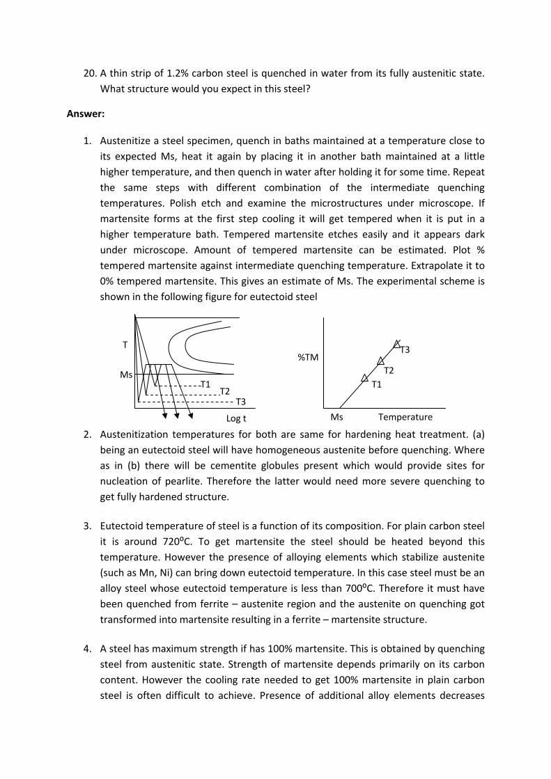
20. A thin strip of 1.2% carbon steel is quenched in water from its fully austenitic state.
What structure would you expect in this steel?
Answer:
1. Austenitize a steel specimen, quench in baths maintained at a temperature close to
its expected Ms, heat it again by placing it in another bath maintained at a little
higher temperature, and then quench in water after holding it for some time. Repeat
the same steps with different combination of the intermediate quenching
temperatures. Polish etch and examine the microstructures under microscope. If
martensite forms at the first step cooling it will get tempered when it is put in a
higher temperature bath. Tempered martensite etches easily and it appears dark
under microscope. Amount of tempered martensite can be estimated. Plot %
tempered martensite against intermediate quenching temperature. Extrapolate it to
0% tempered martensite. This gives an estimate of Ms. The experimental scheme is
shown in the following figure for eutectoid steel
2. Austenitization temperatures for both are same for hardening heat treatment. (a)
being an eutectoid steel will have homogeneous austenite before quenching. Where
as in (b) there will be cementite globules present which would provide sites for
nucleation of pearlite. Therefore the latter would need more severe quenching to
get fully hardened structure.
3. Eutectoid temperature of steel is a function of its composition. For plain carbon steel
it is around 720⁰C. To get martensite the steel should be heated beyond this
temperature. However the presence of alloying elements which stabilize austenite
(such as Mn, Ni) can bring down eutectoid temperature. In this case steel must be an
alloy steel whose eutectoid temperature is less than 700⁰C. Therefore it must have
been quenched from ferrite – austenite region and the austenite on quenching got
transformed into martensite resulting in a ferrite – martensite structure.
4. A steel has maximum strength if has 100% martensite. This is obtained by quenching
steel from austenitic state. Strength of martensite depends primarily on its carbon
content. However the cooling rate needed to get 100% martensite in plain carbon
steel is often difficult to achieve. Presence of additional alloy elements decreases
T
Ms
Log t
T1 T2
T3
%TM
Temperature Ms
T1
T2
T3
critical cooling rate. Alloy steels are easy to harden. Therefore strength of hardened
steel would depend on its carbon content, section size (thickness) and other alloy
elements present & their amounts in the steel.
5. As against furnace cooling in the case of annealing the job is allowed to cool in air
while normalizing. This being significantly faster normalized structure would have
finer pearlite and a little less amount of ferrite. However the total amount of
cementite would still be the same. Only the carbon content and therefore the
amount of cementite in pearlite would decrease.
6. On quenching the microstructure of steel will consist of martensite and some
retained austenite. Both Ms & Mf temperature of steel decreases with % carbon.
Steels having beyond 0.7%C has subzero Mf temperature.
Exercise:
21. Cooling rate at the center of a steel rod on quenching in oil from 850⁰C is given by
1.4 10 . ⁰C/s, where d is diameter in mm. Which of the following steel
would have 100% martensite at its centre if its diameter is 50mm? Critical cooling
rate (CCR ⁰C/sec) of steel to get 100% martensite is a function of composition.
Assume that it is given by log 4.3 3.3 /1.6 (a) AISI 4340 steel having 0.4C, 0.7Mn, 1.8Ni, 0.8Cr,0.25Mo (b) AISI 3130:
0.3C,0.7Mn,1.3Ni,0.6Cr
22. Find out the diameters of the above steels (see problem 1) that would have 100%
martensite at its center on quenching in the same medium.

23. Explain why thicker sections are more susceptible to cracking during hardening heat
treatment.
24. Critical diameter of a certain grade of steel for oil quench, water quench and ideal
quench are DO, DW and DI respectively. Arrange these in descending order.
25. List the factors that determine hardenability of steel. Which of these are preferred?
Give reasons.
26. What is meant by severity of quench? List the factors that determine this. What is its
dimension?
Answer:
1. Cooling rate at the centre = 1.4 10 50 . 8.28⁰C/sec. CCR of the two steels are (a) 5.8 ⁰C/s (b) 48.4 ⁰C/s. Cooling rate is higher than CCR of (a) but lower than
that of (b). Therefore (a) will have 100% martensite at its center.
2. (a) 5.8 14000 . ∴.
.60.5 (b)
.
.20
3. The difference in cooling rate between the centre and the surface is much more in a
thicker section. As soon as the temperature at the surface crosses Ms temperature,
martensite forms accompanied by volume expansion. The core is still soft austenite
and can accommodate deformation if required. However later when its temperature
goes below Ms it would expand, when outer core which is already transformed is
hard and cannot accommodate deformation. A tensile stress therefore develops at
the surface and it becomes prone to cracking. If thickness is less the difference in
temperature is not large. Transformation takes place almost simultaneously with
little chance of developing high tensile stress at the surface. The following sketch
illustrates this.
4. DI, DW, DO
5. Hardenability increases with increasing carbon content, alloy addition (except
cobalt), lower inclusion content and coarse austenite grain size. The first three are
preferred. Finer grain size gives better crack resistance (toughness). Martensite
formed in coarse austenite grain is more prone to cracking.
6. It a measure of the rate at which heat can be extracted from the quenched steel. It is
defined as the ratio of h/2k where k is the thermal conductivity of steel and h is
convective heat transfer coefficient between steel and quenching medium.
+M
T
Log t
Ms
Dotted line: thin sheet
Firm line: thick sheet. T
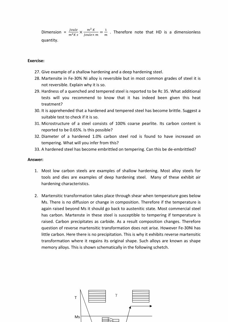
Dimension =
. Therefore note that HD is a dimensionless
quantity.
Exercise:
27. Give example of a shallow hardening and a deep hardening steel.
28. Martensite in Fe‐30% Ni alloy is reversible but in most common grades of steel it is
not reversible. Explain why it is so.
29. Hardness of a quenched and tempered steel is reported to be Rc 35. What additional
tests will you recommend to know that it has indeed been given this heat
treatment?
30. It is apprehended that a hardened and tempered steel has become brittle. Suggest a
suitable test to check if it is so.
31. Microstructure of a steel consists of 100% coarse pearlite. Its carbon content is
reported to be 0.65%. Is this possible?
32. Diameter of a hardened 1.0% carbon steel rod is found to have increased on
tempering. What will you infer from this?
33. A hardened steel has become embrittled on tempering. Can this be de‐embrittled?
Answer:
1. Most low carbon steels are examples of shallow hardening. Most alloy steels for
tools and dies are examples of deep hardening steel. Many of these exhibit air
hardening characteristics.
2. Martensitic transformation takes place through shear when temperature goes below
Ms. There is no diffusion or change in composition. Therefore if the temperature is
again raised beyond Ms it should go back to austenitic state. Most commercial steel
has carbon. Martenste in these steel is susceptible to tempering if temperature is
raised. Carbon precipitates as carbide. As a result composition changes. Therefore
question of reverse martensitic transformation does not arise. However Fe‐30Ni has
little carbon. Here there is no precipitation. This is why it exhibits reverse martensitic
transformation where it regains its original shape. Such alloys are known as shape
memory alloys. This is shown schematically in the following schetch.
T
Ms
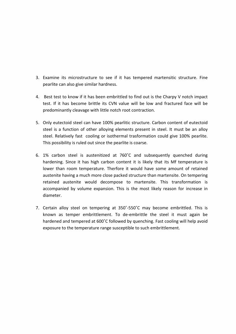
3. Examine its microstructure to see if it has tempered martensitic structure. Fine
pearlite can also give similar hardness.
4. Best test to know if it has been embrittled to find out is the Charpy V notch impact
test. If it has become brittle its CVN value will be low and fractured face will be
predominantly cleavage with little notch root contraction.
5. Only eutectoid steel can have 100% pearlitic structure. Carbon content of eutectoid
steel is a function of other alloying elements present in steel. It must be an alloy
steel. Relatively fast cooling or isothermal trasformation could give 100% pearlite.
This possibility is ruled out since the pearlite is coarse.
6. 1% carbon steel is austenitized at 760˚C and subsequently quenched during
hardening. Since it has high carbon content it is likely that its Mf temperature is
lower than room temperature. Therfore it would have some amount of retained
austenite having a much more close packed structure than martensite. On tempering
retained austenite would decompose to martensite. This transformation is
accompanied by volume expansion. This is the most likely reason for increase in
diameter.
7. Certain alloy steel on tempering at 350˚‐550˚C may become embrittled. This is
known as temper embrittlement. To de‐embrittle the steel it must again be
hardened and tempered at 600˚C followed by quenching. Fast cooling will help avoid
exposure to the temperature range susceptible to such embrittlement.

Exercise:
1. Induction heating followed by quenching is a common method of surface hardening
of steel. Can it be applied to an alloy steel having 18Cr8Ni0.15C?
2. Can steel having 0.1% carbon be case carburized at 850⁰C?
3. Cite three main reasons for surface hardening of steel.
4. Explain why core refining heat treatment may not be required for case carburized
aluminium killed steel.
5. What is the white layer on steel that forms during nitriding?
Answers:
1. No. 18Cr8Ni0.15C is austenitic steel. It cannot be hardened by heating & quenching.
2. It would carburize but the process would be too slow. At 850⁰C it will have ferrite
austenite structure. Solubility of carbon in ferrite is very small. Only the austenitic
region will pick up carbon. The concentration gradient for carbon to diffuse into
austenite is also less. Since both temperature & concentration gradients are low rate
of carbon pick up will be extremely slow. Therefore carburization at 850C is not
recommended. The following figure illustrates how %C at the interfaces can be
estimated.
3. Three most important reasons for surface hardening are: (i) to have hard surface but
soft (tough) core in components like gears, shafts etc. (Hardening is often
accompanied by loss of toughness.) (ii) to overcome section size effect which makes
it difficult to get the required surface hardness in large sections by quenching and
(iii) to get a favorable residual stress on the surface which would inhibit crack
initiation.
4. Purpose of core refining treatment is to get fine austenite grain in case carburized
steel. Aluminum killed steel are resistant to austenitic grain growth. Aluminum
910 850910 723
0.8 0.26
22 0.8
1147 8501147 723
; 1.16
∆ 1.16 0.26 0.9
723
910 850
1147
0.1 0.8 2.0 Cs Ci
%C
T
reacts with dissolved oxygen to form oxide particles during solidification. These are
located along austenite grain boundaries and restrict their movements. In such steel
grain growth during carburization heat treatment may not be significant. This is why
core refining treatment may not be necessary. Steels having micro alloying elements
like Nb, V, and Ti too are resistant to grain growth. These too do not need core
refining treatment.
5. Nitriding is done on steel after it has been hardened and tempered. Sample is heated
to around 500⁰C which is lower than the eutectoid transformation temperature in
Fe‐N phase diagram. The eutectoid consists of ferrite and Fe4N. While some N would
diffuse through ferrite to form fine carbo‐nitrides some may form a white nitride
layer made of Fe4N at the surface. This is hard and brittle. It is harmful and it must be
removed by lapping.
Exercise:
1. Microstructure of a cold rolled annealed mild steel sheet shows elongated pearlitic
region in equiaxed ferritic matrix. Comment on the processing route that will give
this type of microstructure.
2. Name three common grades of steel produced by ingot route. Which of these has
higher yield?
3. Why does compressive stress develops at the surface in a case carburized and
subsequently case hardened steel?
4. Why low carbon content is preferred in most structural application? Is high strength
not a major criterion?
5. What is the composition of the steel designated as 25Mn1S14? What is the role of
sulfur in this steel?
Answer: 1. Elongated pearlite is a sign of cold work whereas equiaxed ferrite means annealed
structure. It looks that the steel was cold worked when both pearlite and ferrite got elongated. Later on annealing just below eutectoid temperature ferrite has re‐crystallized but pearlite remains untransformed. To modify pearlite shape it must be heated above the eutectoid temperature.
2. Steel produced by ingot route is classified as killed, semi‐killed and rimming steel. This is based on the way the dissolved oxygen in molten steel is removed. Rimming steel has the highest yield. The oxygen gets removed by the reaction between dissolved carbon and oxygen with evolution of CO bubbles as the steel cools in mold. This gives the rimming action. Formation of solid crust at the top of the ingot does not allow the gas to go out. It remains entrapped as porosity and balance the shrinkage associated with solidification. There is no shrinkage pipe. Therefore the
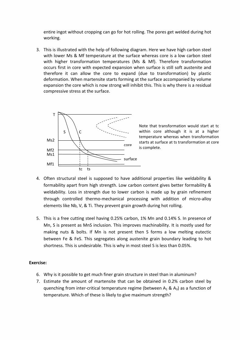
entire ingot without cropping can go for hot rolling. The pores get welded during hot working.
3. This is illustrated with the help of following diagram. Here we have high carbon steel with lower Ms & Mf temperature at the surface whereas core is a low carbon steel with higher transformation temperatures (Ms & Mf). Therefore transformation occurs first in core with expected expansion when surface is still soft austenite and therefore it can allow the core to expand (due to transformation) by plastic deformation. When martensite starts forming at the surface accompanied by volume expansion the core which is now strong will inhibit this. This is why there is a residual compressive stress at the surface.
4. Often structural steel is supposed to have additional properties like weldability &
formability apart from high strength. Low carbon content gives better formability &
weldability. Loss in strength due to lower carbon is made up by grain refinement
through controlled thermo‐mechanical processing with addition of micro‐alloy
elements like Nb, V, & Ti. They prevent grain growth during hot rolling.
5. This is a free cutting steel having 0.25% carbon, 1% Mn and 0.14% S. In presence of
Mn, S is present as MnS inclusion. This improves machinability. It is mostly used for
making nuts & bolts. If Mn is not present then S forms a low melting eutectic
between Fe & FeS. This segregates along austenite grain boundary leading to hot
shortness. This is undesirable. This is why in most steel S is less than 0.05%.
Exercise:
6. Why is it possible to get much finer grain structure in steel than in aluminum?
7. Estimate the amount of martensite that can be obtained in 0.2% carbon steel by
quenching from inter‐critical temperature regime (between A1 & A3) as a function of
temperature. Which of these is likely to give maximum strength?
Ms1
Ms2
Mf2
Mf1 surface
core
C S
T
tc ts
Note that transformation would start at tc within core although it is at a higher temperature whereas when transformation starts at surface at ts transformation at core is complete.
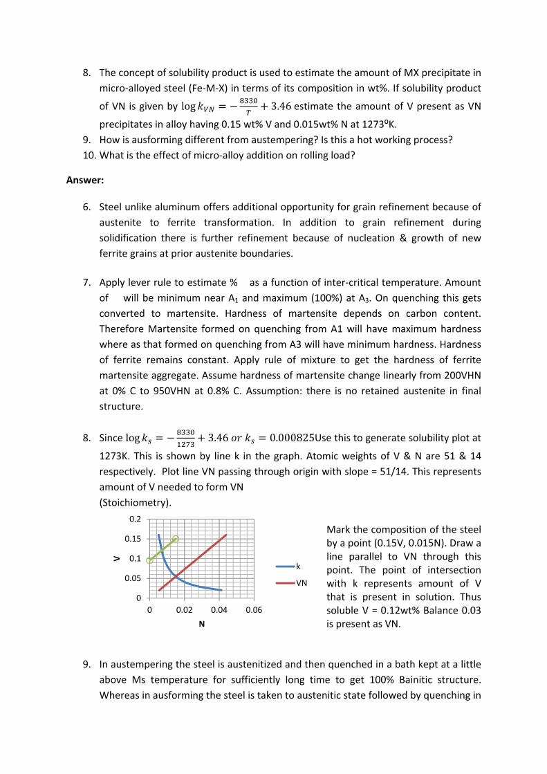
8. The concept of solubility product is used to estimate the amount of MX precipitate in
micro‐alloyed steel (Fe‐M‐X) in terms of its composition in wt%. If solubility product
of VN is given by log 3.46estimate the amount of V present as VN
precipitates in alloy having 0.15 wt% V and 0.015wt% N at 1273⁰K.
9. How is ausforming different from austempering? Is this a hot working process?
10. What is the effect of micro‐alloy addition on rolling load?
Answer:
6. Steel unlike aluminum offers additional opportunity for grain refinement because of
austenite to ferrite transformation. In addition to grain refinement during
solidification there is further refinement because of nucleation & growth of new
ferrite grains at prior austenite boundaries.
7. Apply lever rule to estimate % � as a function of inter‐critical temperature. Amount
of�� will be minimum near A1 and maximum (100%) at A3. On quenching this gets
converted to martensite. Hardness of martensite depends on carbon content.
Therefore Martensite formed on quenching from A1 will have maximum hardness
where as that formed on quenching from A3 will have minimum hardness. Hardness
of ferrite remains constant. Apply rule of mixture to get the hardness of ferrite
martensite aggregate. Assume hardness of martensite change linearly from 200VHN
at 0% C to 950VHN at 0.8% C. Assumption: there is no retained austenite in final
structure.
8. Since log 3.46 0.000825Use this to generate solubility plot at
1273K. This is shown by line k in the graph. Atomic weights of V & N are 51 & 14
respectively. Plot line VN passing through origin with slope = 51/14. This represents
amount of V needed to form VN
(Stoichiometry). Mark the composition of the steel by a point (0.15V, 0.015N). Draw a line parallel to VN through this point. The point of intersection with k represents amount of V that is present in solution. Thus soluble V = 0.12wt% Balance 0.03 is present as VN.
9. In austempering the steel is austenitized and then quenched in a bath kept at a little
above Ms temperature for sufficiently long time to get 100% Bainitic structure.
Whereas in ausforming the steel is taken to austenitic state followed by quenching in
0
0.05
0.1
0.15
0.2
0 0.02 0.04 0.06
V
N
k
VN
a bath kept at a temperature a little above Md and subjected to plastic deformation
before quenching to get martensitic structure. Md temperature corresponds to a
temperature above which martensite does not form even if austenite is being
deformed. Since plastic deformation during ausforming takes place below re‐
crystallization temperature of austenite it is a cold working process.
10. In the case of Nb containing steel grain boundaries get pinned by nano sized NbCN
precipitates formed soon after rolling at high temperature. Finish rolling is done
below its re‐crystallization temperature. This gives rise to elongated austenitic grains
which ultimately transform to ferrite pearlite structure. This process would need
higher rolling load. Whereas steels having V as micro alloy addition precipitation
occurs during finish rolling stage to inhibit grain growth. Therefore rolling load here
is low.
Exercise:
1. Compare the crystal structures of two alloy steels having nominal carbon content (a)
18%Cr (b) 18%Cr8%Ni. Can these be hardened by conventional quenching from a
high temperature?
2. High speed cutting tools are made of 18W4Cr1V0.6C and it is used in hardened and
tempered condition. Unlike normal hardened and tempered plain carbon tool steel it
does not lose its cutting ability even when it is red hot. Explain why it is so.
3. How is the mechanism of strengthening in maraging steel different from that in
conventional ultra high strength steel?
4. Explain why commercial steels / alloys having lower stacking fault energy exhibit
higher creep resistance.
5. Does all steel suitable for ausforming exhibit transformation induced plasticity?
Answers:
1. (a) BCC: ferrite (b) FCC: austenite. 18%Cr steel cannot be transformed to austenite
which is the main criterion for conventional hardening process by heating &
quenching. This is because amount of ferrite stabilizer present is beyond � loop.
Therefore it cannot be hardened by this method. 18Cr8Ni on the other hand is
austenitic at room temperature. Steels that could be hardened by conventional
process develop martensitic structure on quenching to room temperature.
Therefore this too cannot be hardened as above. However through cold work and
subzero quenching some martensite may form in 18Cr8Ni steel.
2. High speed tool steel retains its hardness even when it is red hot because it has
significant amount of strong carbide former which precipitates during the 4th stage
of tempering (gives secondary hardening) before these are put to use. The
precipitate is coherent with the matrix. This gives it excellent micro‐structural
stability to resist particle coarsening and retain its hardness.
3. Martensite in normal steel is hard primarily due to carbon. Presence of excess
carbon is responsible for tetragonal distortion. This is why martensite in normal steel
has BCT structure. Maraging steel has very little carbon. Therefore martensite that
forms here is BCC. In virtual absence of carbon it is soft. It can be cold worked to give
desired shape and increase its strength. On aging at around 500⁰C inter‐metallic
compounds precipitate. This results in further increase in strength. Therefore apart
from solid solution strengthening unlike conventional steel martensite in maraging
steel derives its strength from cold working and precipitation hardening.
4. All creep resisting alloys have precipitates which obstruct movement of dislocation
that is responsible for deformation. Usually precipitates are strong. Stress required
to shear these is high. Therefore dislocations held up at obstacles can move either by
climb (restricted to edge dislocation) or cross slip (restricted to screw dislocation).
There are also restrictions imposed by crystal structure on slip planes and burgers
vectors of mobile dislocations. If stacking fault energy is high the partials join to form
a perfect dislocation that could either cross slip or climb depending on its character.
If SFE is low the distance between the two partial is large. It would require higher
stress to join these. Therefore lower SFE gives higher creep resistance.
5. No not all. Only steels whose Ms temperature is little lower than room temperature
and
Md temperature is higher than room temperature would respond to transformation
induced plasticity if it is heavily deformed above Md temperature. Such steels are in
metastable state during service. If a crack develops in the steel martensite would
form at crack tip. Such a transformation is accompanied by volume expansion
resulting in local deformation. The region surrounding the crack tip would resist such
deformation. Therefore more work has to be done so that the crack would grow.
This gives the steel high yield strength and toughness. Such steels are known as TRIP
steel.
Exercise:
1. Why there is excessive grain growth in the heat affected zone of a welded structure
even if it is made of micro alloyed steel?
2. Most structural steels have some amount Mn primarily to take care of the hot
shortness problem because of residual sulfur in steel. Some amount of Si is also
present. It is added to remove dissolved oxygen in steel. ASTM A516 Grade 60 is a
common grade of steel used for the construction of welded vessels. It has 021C,

0.66Mn, 0.45Si, S <0.035, P < 0.035. Examine if it is suitable for construction of
welded pressure vessel.
3. What are the precautions that need to be taken to weld creep resistant steel tubes
having 0.15C, o.5Mn, 0.54Si, 2.25Cr, 1.0Mo (this corresponds to ASTM T 22 grade
steel)?
4. There is no chance of forming martensite in heat affected zone while welding
austenitic steel. Should therefore all grades of austenitic steels be easily weldable?
Give reasons for your answer.
5. Derive an expression for the time it takes to reach maximum temperature at a
distance r from the heat source during arc welding of a thick plate. Estimate
maximum temperature at a point 5mm away from the heat source during welding of
carbon steel. Material and process parameters are as follows: thermal conductivity =
50W/m/K, density = 7850kg/m3, specific heat = 0.45kJ/kgK, initial temperature of
the plate = 300K, weld current = 150 A, voltage = 20volts, welding speed = 2.5mm/s,
heat lost = 0.4.
6. Use the data given in problem 5 to estimate the distance at which temperature
would reach 1500⁰K (the melting point of the steel).
Answers:
1. Micro‐alloy elements are present in steel as carbo‐nitrides. These are effective in
pinning grain boundaries during normal thermo‐mechanical processing. However
during welding temperature near fusion zone goes beyond their solvus temperature.
Absence of precipitates to pin austenite boundaries in this region leads to excessive
grain growth.
2. Medium carbon steels are more prone to heat affect zone related problem. Although
% C is 0.21 its carbon equivalent = 0.21+0.66/6 = 0.33. This too is less than 0.4% C.
Therefore it can be welded without any special precaution. There is little chance of
formation of hard and brittle martensite from where crack could initiate. Experience
shows that failures often do not take place in the main welds of a structure rather it
initiates from points where a small weld bead may have been placed to attach
ancillary equipments temporarily during fabrication.
3. Carbon equivalent for this steel = 0.15 + 0.54/6 + (2.25+1.0)/5 = 0.89. In this case
martensite is likely to form unless special precautions are taken to preheat the tubes
before
welding. This would help reduce cooling rate encountered in the HAZ during welding.
In many cases post weld heat treatment is also required. Note that most steel
specifications allow a range of composition. To decide whether any special
precaution is necessary carbon equivalent should be estimated using the maximum
permissible alloy content.
4. Totally different kinds of problem are faced during welding of austenitic steel. One is
related to solidification shrinkage which is much more than in ferritic steel. This is
overcome by suitable control of the composition of weld consumables so that on
solidification it has some amount of delta ferrite. Ferrite meters, a non destructive
testing tool to detect if there is some delta ferrite. The second problem is associated
with the precipitation of Cr23C6 at grain boundaries in the heat affected zone. The
carbides have very high amount of chromium. Whenever such precipitates are
formed chromium content of the surrounding matrix drops below the minimum
amount needed to form protective oxide layer. These regions become prone to
corrosive attack. Often it leads to inter granular failure. This phenomenon is known
as sensitization. Stainless characteristics of sensitized steel can be restored by giving
post weld annealing by heating to 950˚C followed by rapid cooling to suppress
carbide precipitation. Alternatively select special low carbon austentic steels or
those having additional alloy elements like Nb. This is a strong carbide forming
element. It does not allow any carbon to be present in the matrix to form Cr23C6.
5. Temperature at distance r from a moving point heat source is given by the following
expression: where T is temperature, t is time, � is thermal
diffusivity, v is welding speed, ��is thermal conductivity, T0 is initial temperature of
the plate, q =�iV where i = current, V = voltage, � = efficiency, � =��/(�c) where���=
density and c = specific heat. To find out time at which T reaches maximum at a
given point r equate: 0 . Since
or 0 ∴ On substituting this in the expression
for T: On substituting numerical values one directly gets both
tmax and Tmax. . 7850 450 1.77 and
300 .
. . .777⁰ .
6. The expression for Tmax can be rewritten as
/ 2 = 0.6 150 20 1.42 10 / 2 50 2.7180.0025 1200 0.00316


![1 Physical Metallurgy- Solid Solution[1]](https://cdn.vdocuments.site/doc/165x107/54f96d114a79599d368b4609/1-physical-metallurgy-solid-solution1.jpg)


