Priodeep Chowdhury, Lecturer, Dept. of CEE, Uttara University.// Water & Water Supply
WATER TREATMENTOverview of the Water Treatment Process Preliminary Treatment
Presedimentation Aeration Primary Sedimentation Sedimentation and flotation zones
Adsorption Ion Exchange Coagulation and Flocculation Filtration Membrane Processes / Electro-dialysis Nanofiltration and reverse osmosis Softening Treatment
Groundwater types and treatment Surface water treatment
DisinfectionPreliminary Treatment
Preliminary treatment is any physical, chemical or mechanical process used on water before it undergoes themain treatment process.
The purpose of preliminary treatment processes is to remove any materials which will interfere with furthertreatment.
Pretreatment may include screening, presedimentation, chemical addition, flow measurement, and aeration.
SCREENING
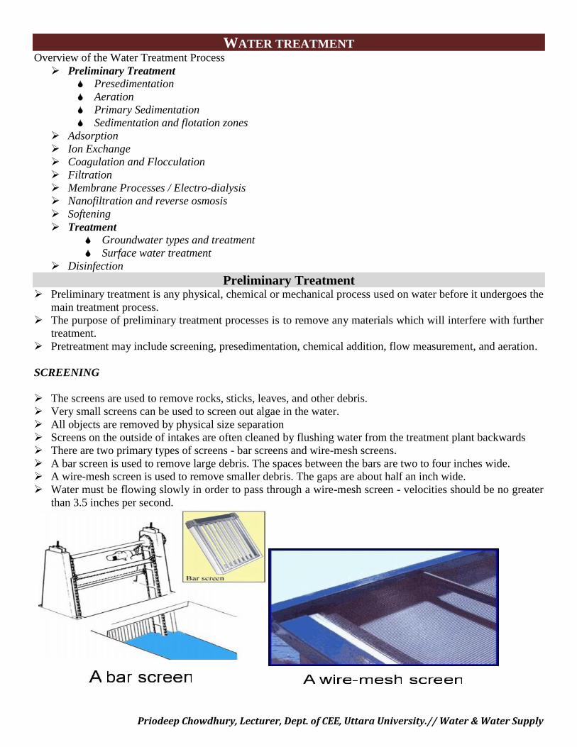
The screens are used to remove rocks, sticks, leaves, and other debris. Very small screens can be used to screen out algae in the water. All objects are removed by physical size separation Screens on the outside of intakes are often cleaned by flushing water from the treatment plant backwards There are two primary types of screens - bar screens and wire-mesh screens. A bar screen is used to remove large debris. The spaces between the bars are two to four inches wide. A wire-mesh screen is used to remove smaller debris. The gaps are about half an inch wide. Water must be flowing slowly in order to pass through a wire-mesh screen - velocities should be no greater
than 3.5 inches per second.
Priodeep Chowdhury, Lecturer, Dept. of CEE, Uttara University.// Water & Water Supply
WATER TREATMENTOverview of the Water Treatment Process Preliminary Treatment
Presedimentation Aeration Primary Sedimentation Sedimentation and flotation zones
Adsorption Ion Exchange Coagulation and Flocculation Filtration Membrane Processes / Electro-dialysis Nanofiltration and reverse osmosis Softening Treatment
Groundwater types and treatment Surface water treatment
DisinfectionPreliminary Treatment
Preliminary treatment is any physical, chemical or mechanical process used on water before it undergoes themain treatment process.
The purpose of preliminary treatment processes is to remove any materials which will interfere with furthertreatment.
Pretreatment may include screening, presedimentation, chemical addition, flow measurement, and aeration.
SCREENING
The screens are used to remove rocks, sticks, leaves, and other debris. Very small screens can be used to screen out algae in the water. All objects are removed by physical size separation Screens on the outside of intakes are often cleaned by flushing water from the treatment plant backwards There are two primary types of screens - bar screens and wire-mesh screens. A bar screen is used to remove large debris. The spaces between the bars are two to four inches wide. A wire-mesh screen is used to remove smaller debris. The gaps are about half an inch wide. Water must be flowing slowly in order to pass through a wire-mesh screen - velocities should be no greater
than 3.5 inches per second.
Priodeep Chowdhury, Lecturer, Dept. of CEE, Uttara University.// Water & Water Supply
PRESEDIMENTATION
Presedimentation is to settle out sand, grit, and gravel which will settle rapidly out of the water without theaddition of chemicals at the beginning of the treatment process.
Presedimentation depends on gravity and includes no coagulation and flocculation. Presedimentation will reduce the load on the coagulation/flocculation basin and on the sedimentation
chamber, as well as reducing the volume of coagulant chemicals required to treat the water. Presedimentation basins are useful because raw water entering the plant from a reservoir is usually more
uniform in quality than water entering the plant without such a holding basin Here in pretreatment, the purpose of sedimentation is to make the chemical treatment phase of the water
treatment process more efficient by removing sediment from the raw water. In presedimentation basin, activated carbon may be added to the basin for taste, odor, and color problems,
and some chemicals to control the growth of algae. Aeration removes carbon dioxide and hydrogen sulfide from the water. It also oxidizes the iron and
manganese.
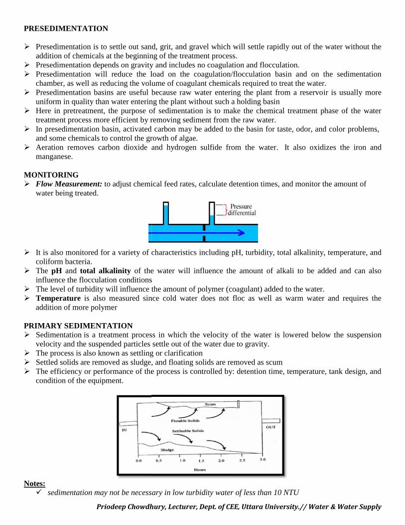
MONITORING Flow Measurement: to adjust chemical feed rates, calculate detention times, and monitor the amount of
water being treated.
It is also monitored for a variety of characteristics including pH, turbidity, total alkalinity, temperature, andcoliform bacteria.
The pH and total alkalinity of the water will influence the amount of alkali to be added and can alsoinfluence the flocculation conditions
The level of turbidity will influence the amount of polymer (coagulant) added to the water. Temperature is also measured since cold water does not floc as well as warm water and requires the
addition of more polymer
PRIMARY SEDIMENTATION Sedimentation is a treatment process in which the velocity of the water is lowered below the suspension
velocity and the suspended particles settle out of the water due to gravity. The process is also known as settling or clarification Settled solids are removed as sludge, and floating solids are removed as scum The efficiency or performance of the process is controlled by: detention time, temperature, tank design, and
condition of the equipment.
Notes: sedimentation may not be necessary in low turbidity water of less than 10 NTU
Priodeep Chowdhury, Lecturer, Dept. of CEE, Uttara University.// Water & Water Supply
PRESEDIMENTATION
Presedimentation is to settle out sand, grit, and gravel which will settle rapidly out of the water without theaddition of chemicals at the beginning of the treatment process.
Presedimentation depends on gravity and includes no coagulation and flocculation. Presedimentation will reduce the load on the coagulation/flocculation basin and on the sedimentation
chamber, as well as reducing the volume of coagulant chemicals required to treat the water. Presedimentation basins are useful because raw water entering the plant from a reservoir is usually more
uniform in quality than water entering the plant without such a holding basin Here in pretreatment, the purpose of sedimentation is to make the chemical treatment phase of the water
treatment process more efficient by removing sediment from the raw water. In presedimentation basin, activated carbon may be added to the basin for taste, odor, and color problems,
and some chemicals to control the growth of algae. Aeration removes carbon dioxide and hydrogen sulfide from the water. It also oxidizes the iron and
manganese.
MONITORING Flow Measurement: to adjust chemical feed rates, calculate detention times, and monitor the amount of
water being treated.
It is also monitored for a variety of characteristics including pH, turbidity, total alkalinity, temperature, andcoliform bacteria.
The pH and total alkalinity of the water will influence the amount of alkali to be added and can alsoinfluence the flocculation conditions
The level of turbidity will influence the amount of polymer (coagulant) added to the water. Temperature is also measured since cold water does not floc as well as warm water and requires the
addition of more polymer
PRIMARY SEDIMENTATION Sedimentation is a treatment process in which the velocity of the water is lowered below the suspension
velocity and the suspended particles settle out of the water due to gravity. The process is also known as settling or clarification Settled solids are removed as sludge, and floating solids are removed as scum The efficiency or performance of the process is controlled by: detention time, temperature, tank design, and
condition of the equipment.
Notes: sedimentation may not be necessary in low turbidity water of less than 10 NTU
Priodeep Chowdhury, Lecturer, Dept. of CEE, Uttara University.// Water & Water Supply
In this case, coagulation and flocculation are used to produce pinpoint (very small) floc which isremoved from the water in the filters.
Primary Sedimentation: Location in the Treatment Process
The most common form of sedimentation follows coagulation and flocculation and precedes filtration. This type of sedimentation requires chemical addition (in the coagulation/flocculation step) and removes the
resulting floc from the water. sedimentation following coagulation/flocculation is meant to remove most of the suspended particles in the
water before the water reaches the filters, Sedimentation at this stage in the treatment process should remove 90% of the suspended particles from the
water, including bacteria. The purpose of sedimentation here is to decrease the concentration of suspended particles in the water,
reducing the load on the filters. Sedimentation can also occur as part of the pretreatment process, where it is known as presedimentation.
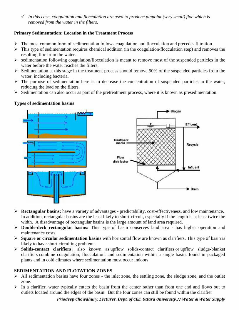
Types of sedimentation basins
Rectangular basins: have a variety of advantages - predictability, cost-effectiveness, and low maintenance.In addition, rectangular basins are the least likely to short-circuit, especially if the length is at least twice thewidth. A disadvantage of rectangular basins is the large amount of land area required.
Double-deck rectangular basins: This type of basin conserves land area - has higher operation andmaintenance costs.
Square or circular sedimentation basins with horizontal flow are known as clarifiers. This type of basin islikely to have short-circuiting problems.
Solids-contact clarifiers , also known as upflow solids-contact clarifiers or upflow sludge-blanketclarifiers combine coagulation, flocculation, and sedimentation within a single basin. found in packagedplants and in cold climates where sedimentation must occur indoors
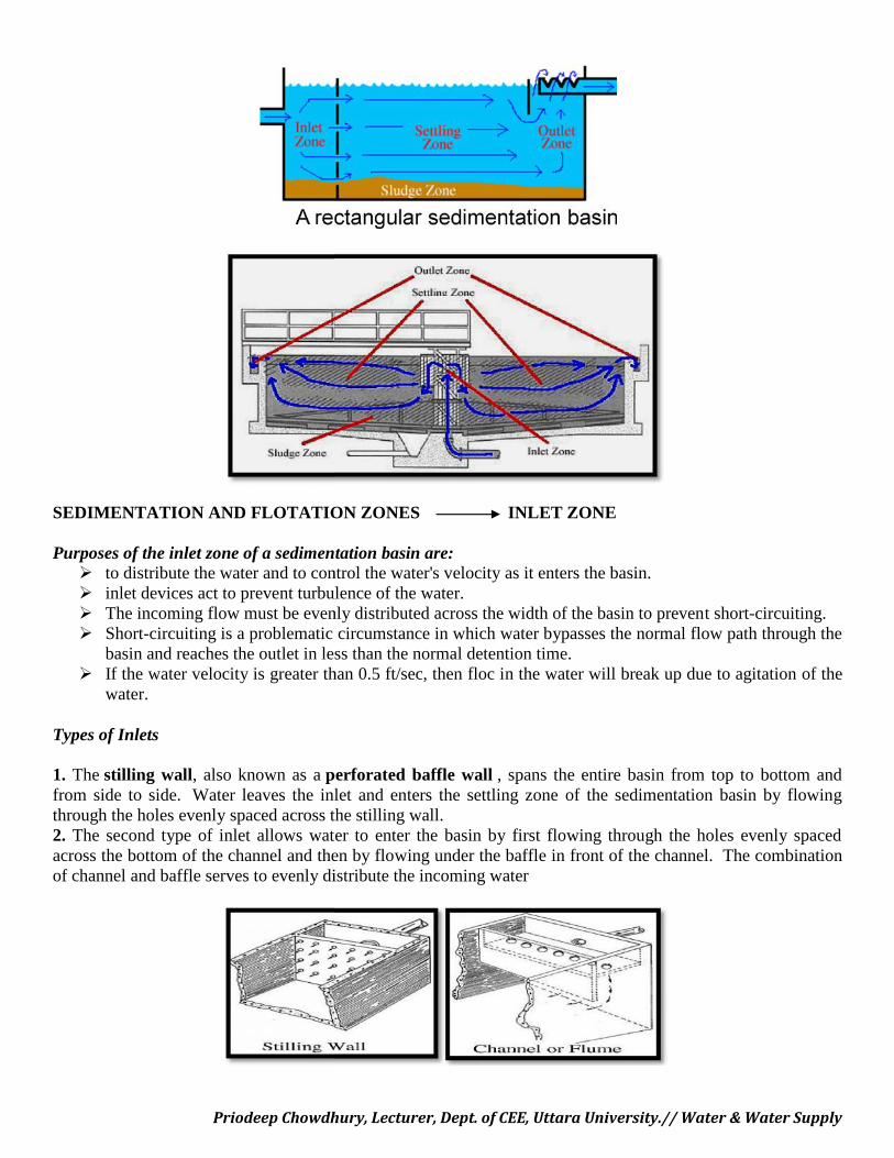
SEDIMENTATION AND FLOTATION ZONES All sedimentation basins have four zones - the inlet zone, the settling zone, the sludge zone, and the outlet
zone. In a clarifier, water typically enters the basin from the center rather than from one end and flows out to
outlets located around the edges of the basin. But the four zones can still be found within the clarifier
Priodeep Chowdhury, Lecturer, Dept. of CEE, Uttara University.// Water & Water Supply
In this case, coagulation and flocculation are used to produce pinpoint (very small) floc which isremoved from the water in the filters.
Primary Sedimentation: Location in the Treatment Process
The most common form of sedimentation follows coagulation and flocculation and precedes filtration. This type of sedimentation requires chemical addition (in the coagulation/flocculation step) and removes the
resulting floc from the water. sedimentation following coagulation/flocculation is meant to remove most of the suspended particles in the
water before the water reaches the filters, Sedimentation at this stage in the treatment process should remove 90% of the suspended particles from the
water, including bacteria. The purpose of sedimentation here is to decrease the concentration of suspended particles in the water,
reducing the load on the filters. Sedimentation can also occur as part of the pretreatment process, where it is known as presedimentation.
Types of sedimentation basins
Rectangular basins: have a variety of advantages - predictability, cost-effectiveness, and low maintenance.In addition, rectangular basins are the least likely to short-circuit, especially if the length is at least twice thewidth. A disadvantage of rectangular basins is the large amount of land area required.
Double-deck rectangular basins: This type of basin conserves land area - has higher operation andmaintenance costs.
Square or circular sedimentation basins with horizontal flow are known as clarifiers. This type of basin islikely to have short-circuiting problems.
Solids-contact clarifiers , also known as upflow solids-contact clarifiers or upflow sludge-blanketclarifiers combine coagulation, flocculation, and sedimentation within a single basin. found in packagedplants and in cold climates where sedimentation must occur indoors
SEDIMENTATION AND FLOTATION ZONES All sedimentation basins have four zones - the inlet zone, the settling zone, the sludge zone, and the outlet
zone. In a clarifier, water typically enters the basin from the center rather than from one end and flows out to
outlets located around the edges of the basin. But the four zones can still be found within the clarifier
Priodeep Chowdhury, Lecturer, Dept. of CEE, Uttara University.// Water & Water Supply
SEDIMENTATION AND FLOTATION ZONES INLET ZONE
Purposes of the inlet zone of a sedimentation basin are: to distribute the water and to control the water's velocity as it enters the basin. inlet devices act to prevent turbulence of the water. The incoming flow must be evenly distributed across the width of the basin to prevent short-circuiting. Short-circuiting is a problematic circumstance in which water bypasses the normal flow path through the
basin and reaches the outlet in less than the normal detention time. If the water velocity is greater than 0.5 ft/sec, then floc in the water will break up due to agitation of the
water.
Types of Inlets
1. The stilling wall, also known as a perforated baffle wall , spans the entire basin from top to bottom andfrom side to side. Water leaves the inlet and enters the settling zone of the sedimentation basin by flowingthrough the holes evenly spaced across the stilling wall.2. The second type of inlet allows water to enter the basin by first flowing through the holes evenly spacedacross the bottom of the channel and then by flowing under the baffle in front of the channel. The combinationof channel and baffle serves to evenly distribute the incoming water
Priodeep Chowdhury, Lecturer, Dept. of CEE, Uttara University.// Water & Water Supply
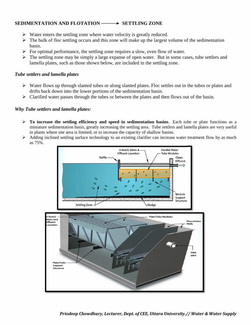
SEDIMENTATION AND FLOTATION SETTLING ZONE
Water enters the settling zone where water velocity is greatly reduced. The bulk of floc settling occurs and this zone will make up the largest volume of the sedimentation
basin. For optimal performance, the settling zone requires a slow, even flow of water. The settling zone may be simply a large expanse of open water. But in some cases, tube settlers and
lamella plates, such as those shown below, are included in the settling zone.
Tube settlers and lamella plates
Water flows up through slanted tubes or along slanted plates. Floc settles out in the tubes or plates anddrifts back down into the lower portions of the sedimentation basin.
Clarified water passes through the tubes or between the plates and then flows out of the basin.
Why Tube settlers and lamella plates:
To increase the settling efficiency and speed in sedimentation basins. Each tube or plate functions as aminiature sedimentation basin, greatly increasing the settling area. Tube settlers and lamella plates are very usefulin plants where site area is limited, or to increase the capacity of shallow basins.
Adding inclined settling surface technology to an existing clarifier can increase water treatment flow by as muchas 75%.
Priodeep Chowdhury, Lecturer, Dept. of CEE, Uttara University.// Water & Water Supply
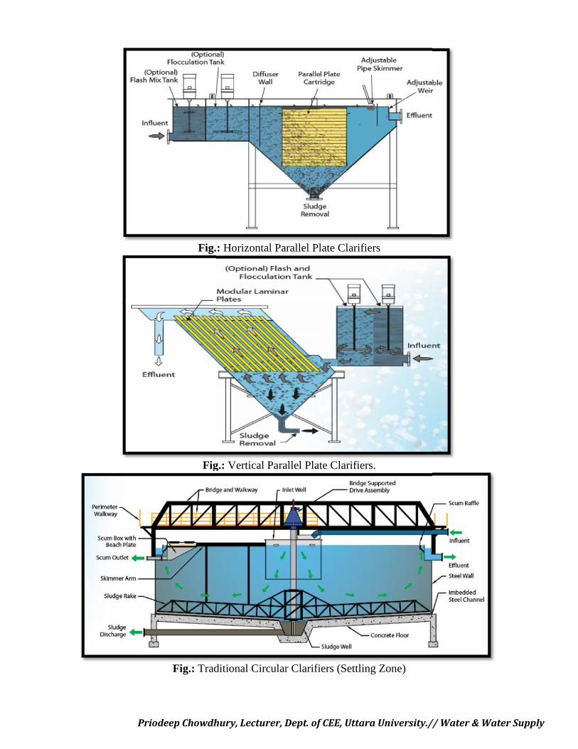
Fig.: Horizontal Parallel Plate Clarifiers
Fig.: Vertical Parallel Plate Clarifiers.
Fig.: Traditional Circular Clarifiers (Settling Zone)
Priodeep Chowdhury, Lecturer, Dept. of CEE, Uttara University.// Water & Water Supply
Fig.: Horizontal Parallel Plate Clarifiers
Fig.: Vertical Parallel Plate Clarifiers.
Fig.: Traditional Circular Clarifiers (Settling Zone)
Priodeep Chowdhury, Lecturer, Dept. of CEE, Uttara University.// Water & Water Supply
Fig.: Horizontal Parallel Plate Clarifiers
Fig.: Vertical Parallel Plate Clarifiers.
Fig.: Traditional Circular Clarifiers (Settling Zone)
Priodeep Chowdhury, Lecturer, Dept. of CEE, Uttara University.// Water & Water Supply
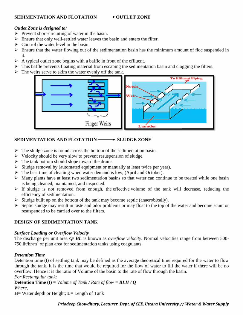
SEDIMENTATION AND FLOTATION OUTLET ZONE
Outlet Zone is designed to: Prevent short-circuiting of water in the basin. Ensure that only well-settled water leaves the basin and enters the filter. Control the water level in the basin. Ensure that the water flowing out of the sedimentation basin has the minimum amount of floc suspended in
it. A typical outlet zone begins with a baffle in front of the effluent. This baffle prevents floating material from escaping the sedimentation basin and clogging the filters. The weirs serve to skim the water evenly off the tank.
SEDIMENTATION AND FLOTATION SLUDGE ZONE
The sludge zone is found across the bottom of the sedimentation basin. Velocity should be very slow to prevent resuspension of sludge. The tank bottom should slope toward the drains Sludge removal by (automated equipment or manually at least twice per year). The best time of cleaning when water demand is low, (April and October). Many plants have at least two sedimentation basins so that water can continue to be treated while one basin
is being cleaned, maintained, and inspected. If sludge is not removed from enough, the effective volume of the tank will decrease, reducing the
efficiency of sedimentation. Sludge built up on the bottom of the tank may become septic (anaerobically). Septic sludge may result in taste and odor problems or may float to the top of the water and become scum or
resuspended to be carried over to the filters.
DESIGN OF SEDIMENTATION TANK
Surface Loading or Overflow VelocityThe discharge per unit area Q/ BL is known as overflow velocity. Normal velocities range from between 500-750 lit/hr/m2 of plan area for sedimentation tanks using coagulants.
Detention TimeDetention time (t) of settling tank may be defined as the average theoretical time required for the water to flowthrough the tank. It is the time that would be required for the flow of water to fill the water if there will be nooverflow. Hence it is the ratio of Volume of the basin to the rate of flow through the basin.For Rectangular tank:Detention Time (t) = Volume of Tank / Rate of flow = BLH / QWhere,H= Water depth or Height; L= Length of Tank
Priodeep Chowdhury, Lecturer, Dept. of CEE, Uttara University.// Water & Water Supply
B= Width; Q= DischargeDetention time usually ranges between 4 to 8 hours for plain sedimentation; it is 2 to 4 hrs., as coagulant getused.
Short CircuitingFor the efficient removal of sediment in sedimentation tank, it is necessary that flow through period uniformlydistributed throughout the tank. If current permit a substantial portion of water to pass directly through the tankwithout being detained for intended time, the flow is said to be short circuited.
Inlet & Out let ZoneInlet & Outlet zone near the entrance and exit should be designed which may reduce the short-circuitingtendencies and in such a way distribute the flow uniformly. The size and shape of particle also affect the settlingrate. The greater is the specific gravity more readily the particle will settle.
Displacement Efficiency The actual average time, which a batch of water takes in passing through a settling tank is called the flowing
through period it is always less than the detention period. Which is the corresponding theoretical time. Theratio of the flowing through period to detention time is called ‘displacement efficiency’
Therefore, Displacement efficiency= Flow through period / Detention Period It generally varies between 0.25 to 0.5 in normal sedimentation tank.
Basin Dimension The surface area of the tank is determined on the basis of overflow rate or surface loading rate Surface Area A= Rate of flow (m3/day) / Surface loading rate (m3/m2/day) The length to width ratio of rectangle tank should preferably be 3:1 to 5:1 Width of tank should not exceed
12 m. The depth is kept between 3 to 6 m. For a circular tank the diameter is limited to 60 m C/s area is such that to provide a horizontal velocity of flow of 0.2 to 0.4 m/min, normally about 0.3 m/min. Bottom slope is taken as 1 % in rectangular tank to about 8% in circular tank
Maximum velocity to prevent scour It is very essential that once the particle has settled and reach the sludge zone it should not be scoured or
lifted up by velocity of flow of water over the bed. Vd= ( 8 β*(Ss-1)* d/f) 1/2
Where;β = 0.04 for uni-granular sand and 0.06 or more for non uniform sand.f = Darcy Weisbach friction factor
= 0.025 to 0.03 for settling velocity.d = diameter of particleSs = Specific Gravity of particles
Sludge RemovalThe particles settled in the basin constitute the sludge which can be removed either manually or mechanically.In manual process the tank has to be put out of service, drained and sludge has to be dug out from the bottommanually. This method is used when the quantity of matter is small. However when quantity is large,mechanical or hydraulic methods are used for sludge removal.
Problem-1:Design a suitable sedimentation tank for a town whose daily demand is 12 million lit per day. Tank is fittedwith a mechanical scrapper for sludge removal. Assume detention period as 5 hrs. And velocity of flow as 20cm/sec.Solution:Quantity of water to be treated = 12 x 10 6 lit/ day = 12 x 10 3 m3 /day =12 x 10 3 / 24 = 500 m3/hr
Priodeep Chowdhury, Lecturer, Dept. of CEE, Uttara University.// Water & Water Supply
Capacity of tank = Q x detention time= 500 x 5= 2500 m3
Velocity of flow = 20 cm /min = 0.2 m/minThe length of the tank required = Velocity of flow x Detention time
= 0.2 x 5 x 60= 60 m
The c/s area of the tank required = Volume of tank / Length of the tank = 2500/ 60 = 41.66 m2
Assume water depth of 3.5 m
Width of tank required = 41.66 / 3.5= 11.9 m => 12 m
Using free board of 0.5 m the overall depth = 3.5 + 0.5 = 4.0 mSo provide a tank of 60 x 12 x 4 mSurface loading rate = Q / (L x B) = 12 x 103/60 x 12 = 16.66 m3/m2/day (Within limits) <O.K.>
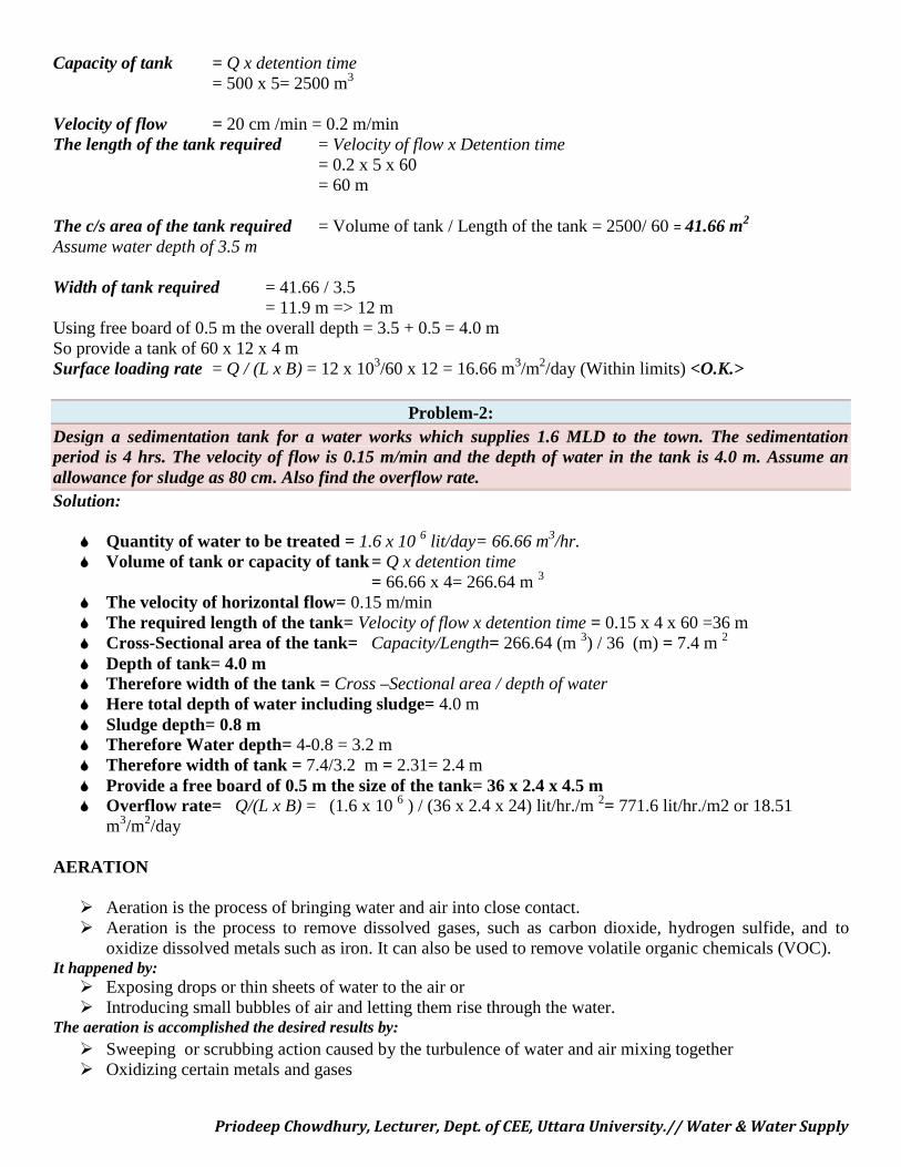
Problem-2:Design a sedimentation tank for a water works which supplies 1.6 MLD to the town. The sedimentationperiod is 4 hrs. The velocity of flow is 0.15 m/min and the depth of water in the tank is 4.0 m. Assume anallowance for sludge as 80 cm. Also find the overflow rate.Solution:
Quantity of water to be treated = 1.6 x 10 6 lit/day= 66.66 m3/hr. Volume of tank or capacity of tank= Q x detention time
= 66.66 x 4= 266.64 m 3
The velocity of horizontal flow= 0.15 m/min The required length of the tank= Velocity of flow x detention time = 0.15 x 4 x 60 =36 m Cross-Sectional area of the tank= Capacity/Length= 266.64 (m 3) / 36 (m) = 7.4 m 2
Depth of tank= 4.0 m Therefore width of the tank = Cross –Sectional area / depth of water Here total depth of water including sludge= 4.0 m Sludge depth= 0.8 m Therefore Water depth= 4-0.8 = 3.2 m Therefore width of tank = 7.4/3.2 m = 2.31= 2.4 m Provide a free board of 0.5 m the size of the tank= 36 x 2.4 x 4.5 m Overflow rate= Q/(L x B) = (1.6 x 10 6 ) / (36 x 2.4 x 24) lit/hr./m 2= 771.6 lit/hr./m2 or 18.51
m3/m2/day
AERATION
Aeration is the process of bringing water and air into close contact. Aeration is the process to remove dissolved gases, such as carbon dioxide, hydrogen sulfide, and to
oxidize dissolved metals such as iron. It can also be used to remove volatile organic chemicals (VOC).It happened by: Exposing drops or thin sheets of water to the air or Introducing small bubbles of air and letting them rise through the water.
The aeration is accomplished the desired results by: Sweeping or scrubbing action caused by the turbulence of water and air mixing together Oxidizing certain metals and gases
Priodeep Chowdhury, Lecturer, Dept. of CEE, Uttara University.// Water & Water Supply
CHEMICAL SUBSTANCES AFFECTED BY AERATIONThe constituents that are commonly affected by aeration are:
Volatile organic chemicals, such as benzene, found in gasoline, or trichloroethylene, dichloroethylene,and perchloroethylene, examples of solvents are used in dry cleaning or industrial processes.
Carbon dioxide Hydrogen sulfide (rotten-egg odor) Methane (flammable) Iron (will stain clothes and fixtures) Manganese (black stains) Various chemicals causing taste and odor
Chemical Substances Affected By Aeration: CO2
Surface waters have a low CO2 content ( 0 to 2 mg/l). Deep lake or reservoir can have high CO2 content due to the respiration of microscopic animals and lack of
abundant plant growth at the lake bottom. Aerators remove CO2 by the physical scrubbing or sweeping action caused by turbulence. aeration can reduce the CO2 content to 4.5 mg CO2 /l Concentrations of CO2 in groundwater are usually higher than in surface water. Water from a deep well normally contains less than 50 mg/l, but a shallow well can have a much higher
level, up to 50 to 300 mg/l.
CO2 REMOVAL
The most appropriate treatment for carbon dioxide may be aeration, addition of an alkali, or acombination of the two.
CO2 gas dissolves easily in water, resulting in carbonic acid:H2O + CO2 <===> H2CO3
CO2 is neutralized through the addition of an alkali (basic, ionic salt), such as lime (Ca(OH)2) or sodaash (Na2CO3).
Lime reacts with carbon dioxide, removing the carbon dioxide from the water as shown below:CO2 + Ca(OH)2 <===> CaCO3 + H2O
CO2 above 5 to 15 mg/l in raw water can cause three operating problems:
It increases the acidity of the water, making it corrosive by forming a “weak” acid, H2CO3. It tends to keep iron in solution, thus making iron removal more difficult. It reacts with lime added to soften water, causing an increase in the amount of lime needed for the
softening reaction.H2S
A poisonous gas (Brief exposures--less than 30 minutes in concentrations as low as 0.03 percent by volumein the air) - rotten-egg odor
H2S occurs mainly in groundwater supplies. It may be caused by the action of iron or sulphur reducing bacteria in the well. Occasional disinfection of the well can reduce the bacteria producing the H2S H2S in a water supply will disagreeably alter the taste of coffee, tea, and ice. H2S is corrosive to piping, tanks, water heaters, and copper alloys that it contacts.
Operational problems: Disinfection of the water can become less effective because of the chlorine demand exerted by the
hydrogen sulfide.
Priodeep Chowdhury, Lecturer, Dept. of CEE, Uttara University.// Water & Water Supply
H2S + Cl2 + O2- → S + H2O + 2Cl-
H2S + 4Cl2 + 4 H2O → H2SO4 + 8 HCl There could be corrosion of the piping systems and the water tanks.
H2S REMOVAL BY AERATION METHOD
Hydrogen sulfide is physically removed by agitating the water via bubbling or cascading and thenseparating or "stripping" the hydrogen sulfide in a container.
H2S + O2 = water (H2O) + elemental sulfur Aeration is most effective when hydrogen H2S are lower than 2.0 mg/l. At higher concentrations, this method may not remove the entire offensive odor unless the air is used to
oxidize hydrogen sulfide chemically into solid sulfur, which is then filtered. In a typical aeration system, ambient air is introduced into the water using an air compressor or blower. Well-designed aeration tanks maintain a pocket of air in the upper third or upper half of the tank. If the tank does not maintain an air pocket, sulfur odor may return. When sulfur levels exceed 10 mg/l, larger aeration tanks, repressurization systems, chlorination systems, or
a combination may be needed.
METHANE
Methane gas can be found in groundwater. It may be formed by the decomposition of organic matter. It can be found in water from aquifers that are near natural-gas deposits. Methane is a colorless gas that is highly flammable and explosive. When mixed with water, methane will make the water taste like garlic. The gas is only slightly soluble in water and therefore is easily removed by the aeration of the water.
IRON & MANGANESE REMOVAL
Iron and manganese minerals are found in soil and rock. Iron and manganese can dissolve into groundwater as it percolates through the soil and rock. Iron in the ferrous form and manganese in the manganous form are objectionable. More than 0.3 mg/l of iron will cause yellow to reddish-brown stains of plumbing fixtures or almost
anything that it contacts. If the concentration exceeds 1 mg/l, the taste of the water will be metallic and the water may be turbid. Manganese even at levels as low as 0.1 mg/l, will cause blackish staining of fixtures and anything else it
contacts. If the water contains both iron and manganese, staining could vary from dark brown to black. Consumer complaints are laundry is stained and that the water is red or dirty. Iron and manganese should not be aerated unless filtration is provided. Iron and manganese in well waters occur as soluble ferrous and manganous bicarbonates. In the aeration process, the water is saturated with oxygen to promote the following reactions: The oxidation products, ferric hydroxide and manganese dioxide, are insoluble. After aeration, they are removed by clarification or filtration. Occasionally, strong chemical oxidants such as chlorine (Cl2 or potassium permanganate (KMnO4) may be
used following aeration to ensure complete oxidation.
TASTE, ODOR & DISSOLVED OXYGEN REMOVAL
TASTE AND ODOR Aeration is effective in removing tastes and odors that are caused by volatile materials
Priodeep Chowdhury, Lecturer, Dept. of CEE, Uttara University.// Water & Water Supply
Volatile materials (e.g Methane and hydrogen sulfide) have low boiling point and will vaporize veryeasily.
Many taste and odor problems in surface water could be caused by oils and by-products that algaeproduce.
Since oils are much less volatile than gases, aeration is only partially effective.
DISSOLVED OXYGEN Oxygen is injected into water through aeration to remove the flat taste. The amount of oxygen that the water can hold is dependent on the temp. The colder the water, the more oxygen the water can hold. Water that contains excessive amounts of oxygen can become very corrosive. Excessive oxygen can cause air binding of filters.
TYPES OF AERATORS
Aerators fall into two general categories.Introduce air into the water or water into the air. The water-to-air method is designed to produce small drops of water that fall through the air The air-to-water method creates small bubbles of air that are injected into the water stream. All aerators are designed to create a greater amount of contact between the air and water to enhance the
transfer of the gases.
WATER INTO AIR
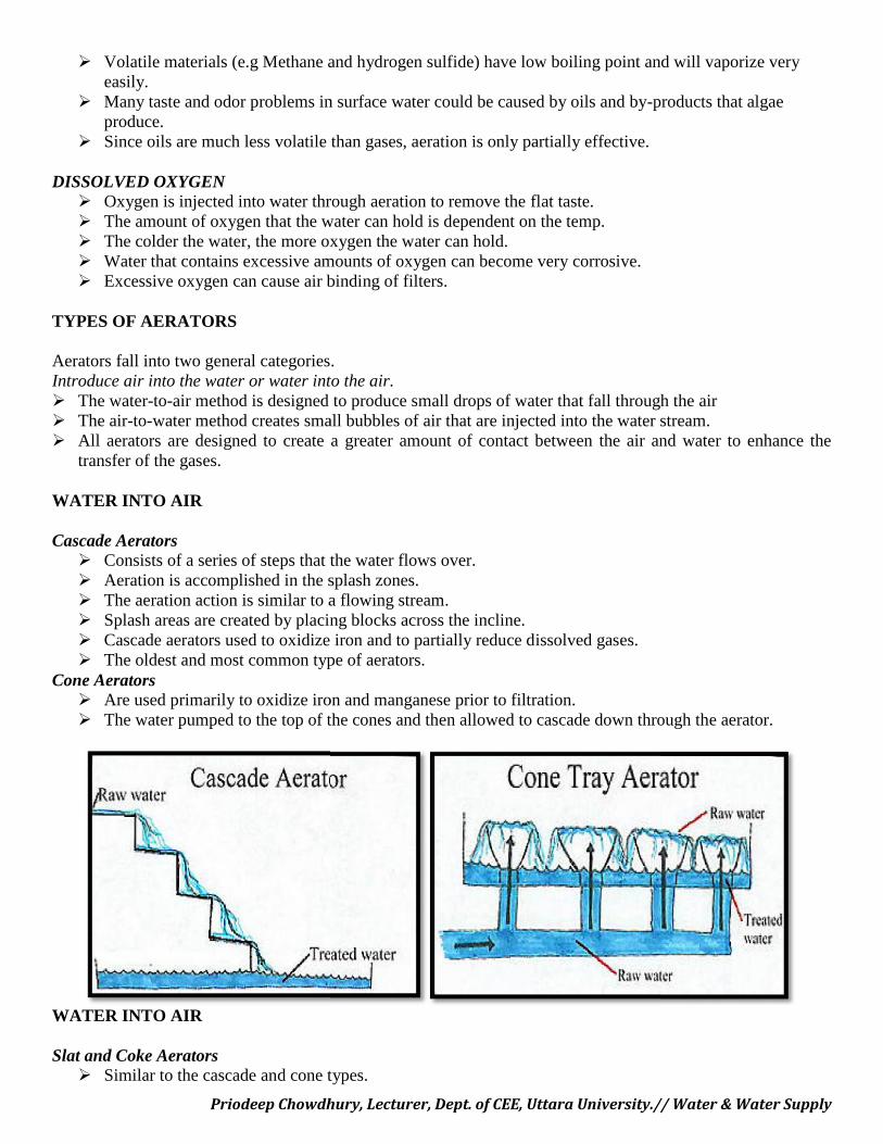
Cascade Aerators Consists of a series of steps that the water flows over. Aeration is accomplished in the splash zones. The aeration action is similar to a flowing stream. Splash areas are created by placing blocks across the incline. Cascade aerators used to oxidize iron and to partially reduce dissolved gases. The oldest and most common type of aerators.
Cone Aerators Are used primarily to oxidize iron and manganese prior to filtration. The water pumped to the top of the cones and then allowed to cascade down through the aerator.
WATER INTO AIR
Slat and Coke Aerators Similar to the cascade and cone types.
Priodeep Chowdhury, Lecturer, Dept. of CEE, Uttara University.// Water & Water Supply
Volatile materials (e.g Methane and hydrogen sulfide) have low boiling point and will vaporize veryeasily.
Many taste and odor problems in surface water could be caused by oils and by-products that algaeproduce.
Since oils are much less volatile than gases, aeration is only partially effective.
DISSOLVED OXYGEN Oxygen is injected into water through aeration to remove the flat taste. The amount of oxygen that the water can hold is dependent on the temp. The colder the water, the more oxygen the water can hold. Water that contains excessive amounts of oxygen can become very corrosive. Excessive oxygen can cause air binding of filters.
TYPES OF AERATORS
Aerators fall into two general categories.Introduce air into the water or water into the air. The water-to-air method is designed to produce small drops of water that fall through the air The air-to-water method creates small bubbles of air that are injected into the water stream. All aerators are designed to create a greater amount of contact between the air and water to enhance the
transfer of the gases.
WATER INTO AIR
Cascade Aerators Consists of a series of steps that the water flows over. Aeration is accomplished in the splash zones. The aeration action is similar to a flowing stream. Splash areas are created by placing blocks across the incline. Cascade aerators used to oxidize iron and to partially reduce dissolved gases. The oldest and most common type of aerators.
Cone Aerators Are used primarily to oxidize iron and manganese prior to filtration. The water pumped to the top of the cones and then allowed to cascade down through the aerator.
WATER INTO AIR
Slat and Coke Aerators Similar to the cascade and cone types.
Priodeep Chowdhury, Lecturer, Dept. of CEE, Uttara University.// Water & Water Supply
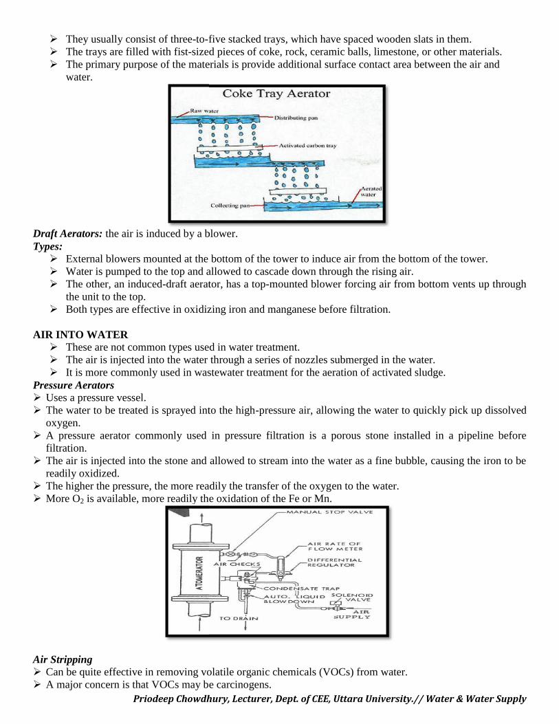
They usually consist of three-to-five stacked trays, which have spaced wooden slats in them. The trays are filled with fist-sized pieces of coke, rock, ceramic balls, limestone, or other materials. The primary purpose of the materials is provide additional surface contact area between the air and
water.
Draft Aerators: the air is induced by a blower.Types: External blowers mounted at the bottom of the tower to induce air from the bottom of the tower. Water is pumped to the top and allowed to cascade down through the rising air. The other, an induced-draft aerator, has a top-mounted blower forcing air from bottom vents up through
the unit to the top. Both types are effective in oxidizing iron and manganese before filtration.
AIR INTO WATER These are not common types used in water treatment. The air is injected into the water through a series of nozzles submerged in the water. It is more commonly used in wastewater treatment for the aeration of activated sludge.
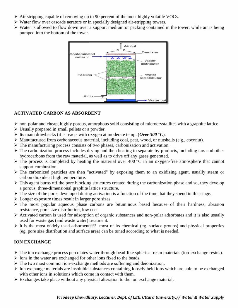
Pressure Aerators Uses a pressure vessel. The water to be treated is sprayed into the high-pressure air, allowing the water to quickly pick up dissolved
oxygen. A pressure aerator commonly used in pressure filtration is a porous stone installed in a pipeline before
filtration. The air is injected into the stone and allowed to stream into the water as a fine bubble, causing the iron to be
readily oxidized. The higher the pressure, the more readily the transfer of the oxygen to the water. More O2 is available, more readily the oxidation of the Fe or Mn.
Air Stripping Can be quite effective in removing volatile organic chemicals (VOCs) from water. A major concern is that VOCs may be carcinogens.
Priodeep Chowdhury, Lecturer, Dept. of CEE, Uttara University.// Water & Water Supply
They usually consist of three-to-five stacked trays, which have spaced wooden slats in them. The trays are filled with fist-sized pieces of coke, rock, ceramic balls, limestone, or other materials. The primary purpose of the materials is provide additional surface contact area between the air and
water.
Draft Aerators: the air is induced by a blower.Types: External blowers mounted at the bottom of the tower to induce air from the bottom of the tower. Water is pumped to the top and allowed to cascade down through the rising air. The other, an induced-draft aerator, has a top-mounted blower forcing air from bottom vents up through
the unit to the top. Both types are effective in oxidizing iron and manganese before filtration.
AIR INTO WATER These are not common types used in water treatment. The air is injected into the water through a series of nozzles submerged in the water. It is more commonly used in wastewater treatment for the aeration of activated sludge.
Pressure Aerators Uses a pressure vessel. The water to be treated is sprayed into the high-pressure air, allowing the water to quickly pick up dissolved
oxygen. A pressure aerator commonly used in pressure filtration is a porous stone installed in a pipeline before
filtration. The air is injected into the stone and allowed to stream into the water as a fine bubble, causing the iron to be
readily oxidized. The higher the pressure, the more readily the transfer of the oxygen to the water. More O2 is available, more readily the oxidation of the Fe or Mn.
Air Stripping Can be quite effective in removing volatile organic chemicals (VOCs) from water. A major concern is that VOCs may be carcinogens.
Priodeep Chowdhury, Lecturer, Dept. of CEE, Uttara University.// Water & Water Supply
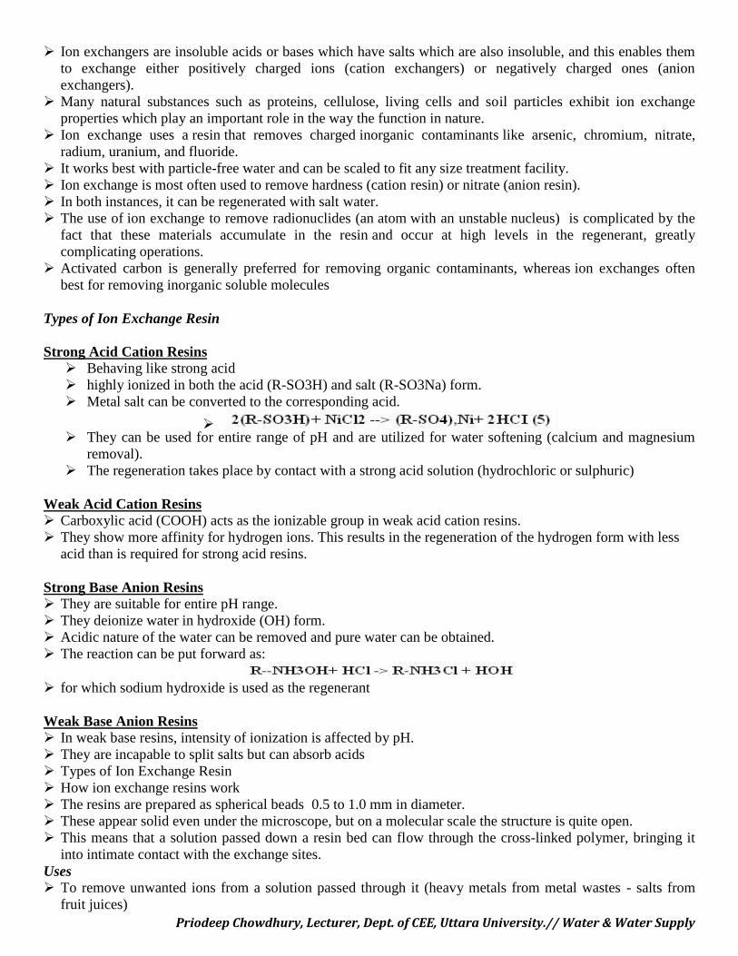
Air stripping capable of removing up to 90 percent of the most highly volatile VOCs. Water flow over cascade aerators or in specially designed air-stripping towers. Water is allowed to flow down over a support medium or packing contained in the tower, while air is being
pumped into the bottom of the tower.
ACTIVATED CARBON AS ABSORBENT
non-polar and cheap, highly porous, amorphous solid consisting of microcrystallites with a graphite lattice Usually prepared in small pellets or a powder. Its main drawbacks (it is reacts with oxygen at moderate temp. (Over 300 °C). Manufactured from carbonaceous material, including coal, peat, wood, or nutshells (e.g., coconut). The manufacturing process consists of two phases, carbonization and activation. The carbonization process includes drying and then heating to separate by-products, including tars and other
hydrocarbons from the raw material, as well as to drive off any gases generated. The process is completed by heating the material over 400 °C in an oxygen-free atmosphere that cannot
support combustion. The carbonized particles are then "activated" by exposing them to an oxidizing agent, usually steam or
carbon dioxide at high temperature. This agent burns off the pore blocking structures created during the carbonization phase and so, they develop
a porous, three-dimensional graphite lattice structure. The size of the pores developed during activation is a function of the time that they spend in this stage. Longer exposure times result in larger pore sizes. The most popular aqueous phase carbons are bituminous based because of their hardness, abrasion
resistance, pore size distribution, low cost Activated carbon is used for adsorption of organic substances and non-polar adsorbates and it is also usually
used for waste gas (and waste water) treatment. It is the most widely used adsorbent??? most of its chemical (eg. surface groups) and physical properties
(eg. pore size distribution and surface area) can be tuned according to what is needed.
ION EXCHANGE
The ion exchange process percolates water through bead-like spherical resin materials (ion-exchange resins). Ions in the water are exchanged for other ions fixed to the beads. The two most common ion-exchange methods are softening and deionization. Ion exchange materials are insoluble substances containing loosely held ions which are able to be exchanged
with other ions in solutions which come in contact with them. Exchanges take place without any physical alteration to the ion exchange material.
Priodeep Chowdhury, Lecturer, Dept. of CEE, Uttara University.// Water & Water Supply
Ion exchangers are insoluble acids or bases which have salts which are also insoluble, and this enables themto exchange either positively charged ions (cation exchangers) or negatively charged ones (anionexchangers).
Many natural substances such as proteins, cellulose, living cells and soil particles exhibit ion exchangeproperties which play an important role in the way the function in nature.
Ion exchange uses a resin that removes charged inorganic contaminants like arsenic, chromium, nitrate,radium, uranium, and fluoride.
It works best with particle-free water and can be scaled to fit any size treatment facility. Ion exchange is most often used to remove hardness (cation resin) or nitrate (anion resin). In both instances, it can be regenerated with salt water. The use of ion exchange to remove radionuclides (an atom with an unstable nucleus) is complicated by the
fact that these materials accumulate in the resin and occur at high levels in the regenerant, greatlycomplicating operations.
Activated carbon is generally preferred for removing organic contaminants, whereas ion exchanges oftenbest for removing inorganic soluble molecules
Types of Ion Exchange Resin
Strong Acid Cation Resins Behaving like strong acid highly ionized in both the acid (R-SO3H) and salt (R-SO3Na) form. Metal salt can be converted to the corresponding acid.
They can be used for entire range of pH and are utilized for water softening (calcium and magnesium
removal). The regeneration takes place by contact with a strong acid solution (hydrochloric or sulphuric)
Weak Acid Cation Resins Carboxylic acid (COOH) acts as the ionizable group in weak acid cation resins. They show more affinity for hydrogen ions. This results in the regeneration of the hydrogen form with less
acid than is required for strong acid resins.
Strong Base Anion Resins They are suitable for entire pH range. They deionize water in hydroxide (OH) form. Acidic nature of the water can be removed and pure water can be obtained. The reaction can be put forward as:
for which sodium hydroxide is used as the regenerant
Weak Base Anion Resins In weak base resins, intensity of ionization is affected by pH. They are incapable to split salts but can absorb acids Types of Ion Exchange Resin How ion exchange resins work The resins are prepared as spherical beads 0.5 to 1.0 mm in diameter. These appear solid even under the microscope, but on a molecular scale the structure is quite open. This means that a solution passed down a resin bed can flow through the cross-linked polymer, bringing it
into intimate contact with the exchange sites.Uses To remove unwanted ions from a solution passed through it (heavy metals from metal wastes - salts from
fruit juices)
Priodeep Chowdhury, Lecturer, Dept. of CEE, Uttara University.// Water & Water Supply
To accumulate a valuable mineral from the water which can later be recovered from the resin. Strong cation resins in the hydrogen form are used for the hydrolysis of starch and sucrose. Used in the laboratory to remove interfering ions during analysis or to accumulate trace quantities of ions
from dilute solutions. A cation resin in the hydrogen form can be used to determine the total concentration of ions in a mixture of
salts. The sample passing through a column is converted to the equivalent quantity of acid and the amountreadily found by titration.
Earliest applications of ion exchange was the separation of rare earth elements (Promethium (element 61)and five new elements in the actinide series).
WATER TREATMENTThe two major types of treatment applied to water are:Water softening - the replacement of ’hard’ ions such as Ca2+ and Mg2+ by Na+
Demineralization - the complete removal of dissolved minerals.
WATER SOFTENING
Softening is used primarily as a pretreatment method to reduce water hardness prior to reverse osmosis (RO)processing.
The softeners contain beads that exchange two sodium ions for every calcium or magnesium ion removedfrom the "softened" water.
In water softening a cation resin in the sodium form is used to remove hard metal ions (calcium andmagnesium) from the water along with troublesome traces of iron and manganese
These ions are replaced by an equivalent quantity of sodium, so that the total dissolved solids content of thewater remains unchanged as does the pH and anionic content.
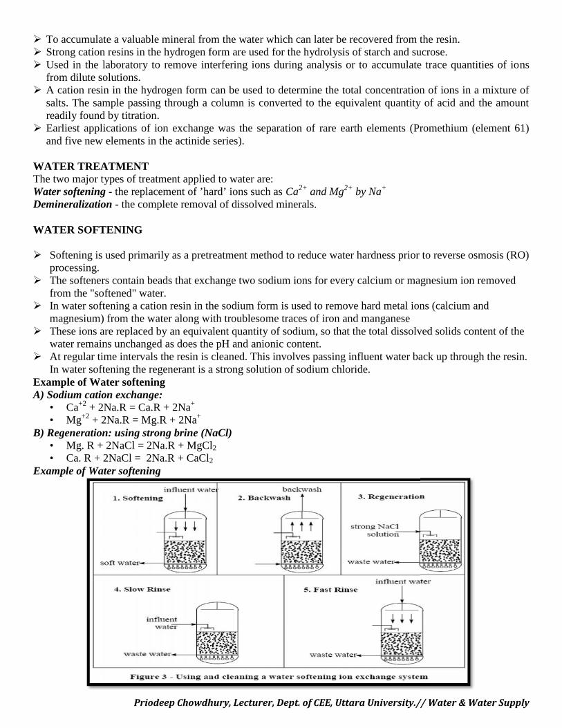
At regular time intervals the resin is cleaned. This involves passing influent water back up through the resin.In water softening the regenerant is a strong solution of sodium chloride.
Example of Water softeningA) Sodium cation exchange:
• Ca+2 + 2Na.R = Ca.R + 2Na+
• Mg+2 + 2Na.R = Mg.R + 2Na+
B) Regeneration: using strong brine (NaCl)• Mg. R + 2NaCl = 2Na.R + MgCl2
• Ca. R + 2NaCl = 2Na.R + CaCl2
Example of Water softening
Priodeep Chowdhury, Lecturer, Dept. of CEE, Uttara University.// Water & Water Supply
To accumulate a valuable mineral from the water which can later be recovered from the resin. Strong cation resins in the hydrogen form are used for the hydrolysis of starch and sucrose. Used in the laboratory to remove interfering ions during analysis or to accumulate trace quantities of ions
from dilute solutions. A cation resin in the hydrogen form can be used to determine the total concentration of ions in a mixture of
salts. The sample passing through a column is converted to the equivalent quantity of acid and the amountreadily found by titration.
Earliest applications of ion exchange was the separation of rare earth elements (Promethium (element 61)and five new elements in the actinide series).
WATER TREATMENTThe two major types of treatment applied to water are:Water softening - the replacement of ’hard’ ions such as Ca2+ and Mg2+ by Na+
Demineralization - the complete removal of dissolved minerals.
WATER SOFTENING
Softening is used primarily as a pretreatment method to reduce water hardness prior to reverse osmosis (RO)processing.
The softeners contain beads that exchange two sodium ions for every calcium or magnesium ion removedfrom the "softened" water.
In water softening a cation resin in the sodium form is used to remove hard metal ions (calcium andmagnesium) from the water along with troublesome traces of iron and manganese
These ions are replaced by an equivalent quantity of sodium, so that the total dissolved solids content of thewater remains unchanged as does the pH and anionic content.
At regular time intervals the resin is cleaned. This involves passing influent water back up through the resin.In water softening the regenerant is a strong solution of sodium chloride.
Example of Water softeningA) Sodium cation exchange:
• Ca+2 + 2Na.R = Ca.R + 2Na+
• Mg+2 + 2Na.R = Mg.R + 2Na+
B) Regeneration: using strong brine (NaCl)• Mg. R + 2NaCl = 2Na.R + MgCl2
• Ca. R + 2NaCl = 2Na.R + CaCl2
Example of Water softening
Priodeep Chowdhury, Lecturer, Dept. of CEE, Uttara University.// Water & Water Supply
Demineralisation = Deionization Complete deionization can be achieved by using two resins. The water is first passed through a bed of cation exchange resin in hydrogen ion form During service, cations in the water are taken up by the resin while hydrogen ions are released. Thus the effluent consists of a very weak mixture of acids. Then water passes through second anion exchange resin in the hydroxide form. Here the anions are exchanged for hydroxide ions, which react with the hydrogen ions to form water. twin bed units will reduce the total solids content to approximately 1-2 mg L-1. it is usual to pass water leaving the cation unit through a degassing tower. degassing tower removes the carbonic acid produced from carbon dioxide and bicarbonate in the feed
water and reduces the load on the anion unit. Without degassing the carbonic acid would be taken up by the anion bed after conversion to carbonate.
Mixed resin
Mixed resin produces water with much lower levels of dissolved material than can be achieved bydistillation.
In laboratories, mixed resin is often used in disposable cartridges. These are only used once, but largermixed resin units can be regenerated.
After exhaustion the bed is subjected to an up flow of water. Anionic resin beads are less dense than the cationic ones and they rise to the top so that the bed is
separated into two layers of resin. Each is regenerated in situ with the appropriate regenerant then rinsed with clean water.
Cation and anion exchange and regenerationi) Hydrogen cation exchange:
M+a + aH.R M.Ra + aH+
Examples:Ca+2 + 2H.R Ca.R2 + 2H+
Na+ + H.R Na.R + H+
Regeneration: using strong acidCa. R + H2SO4 2H.R + CaSO4
2Na. R + H2SO4 2H.R + Na2SO4
ii) Hydroxyl anion exchange:A-b + bR.OH Rb.A + bOH
Examples:NO3
-+ R.OH R.NO3- + OH
CO3-2 + 2 R.OH R2.CO3
-2 + 2OHRegeneration: using strong base (caustic soda)
R.NO3- + NaOH R.OH + NaNO3
R2.CO3-2 + 2NaOH 2R.OH + Na2CO3
Advantages and disadvantages in the use of Ion-Exchange Resins
The advantages of ion exchange processes are: Very low running costs. Very little energy is required, The regenerant chemicals are cheap and if well maintained resin beds can last for many years before
replacement is needed.Disadvantages in the use of Ion-Exchange ResinsCalcium sulphate fouling
Priodeep Chowdhury, Lecturer, Dept. of CEE, Uttara University.// Water & Water Supply
Using Sulphuric acid as cation resin regenerant will react with calcium in water forming calciumsulphate precipitates.
This fouls the resin and blocks drain pipes with a build up of scale (hydrochloric acid must besubstituted).
Iron fouling Aeration allows oxidation of Fe2+ to Fe3+ and consequent precipitation of ferric hydroxide which clogs
resin beads and prevents ion exchange. Iron fouling is the commonest cause of softener failure.Adsorption of organic matter The presence of dissolved organic material can become irreversibly adsorbed within the anion beads,
reducing their exchange capacity. Removal of organics prior to demineralisation is achieved by flocculation with alum or ferric salts
followed by filtration.Organic contamination from the resin The resins themselves can be a source of non-ionized organic contamination. New commercial grade resin often contains organics remaining after manufacture. when removal is
needed, the demineralised water can be passed through an ultra filtration membrane.Bacterial contamination Resin beds do not act as filters for the removal of bacteria. Resin beds can generate a culture media for continued growth. Resins beds can be decontaminated with disinfectants such as formaldehyde Heat or oxidising disinfectants as chlorine must not be used as these damage resins.
Chlorine contamination Chlorine damages resins. It is customary to treat such feeds by passing them through activated carbon
which removes chlorine very efficiently.Environmental Implications The waste water for disposal after regeneration contains all the minerals removed from the water plus
salt from the spent regenerants. Volume of it is equivalent to 1-5% of the treated water throughput.
COAGULATION & FLOCCULATION
WHY THEY ARE USED
All waters, especially surface waters, contain both dissolved and suspended particles. Coagulation andflocculation processes are used to separate the suspended solids portion from the water.The suspended particles vary considerably in source, composition charge, particle size, shape, and density.Correct application of coagulation and flocculation processes and selection of the coagulants depend uponunderstanding the interaction between these factors. The small particles are stabilized (kept in suspension) bythe action of physical forces on the particles themselves. One of the forces playing a dominant role instabilization results from the surface charge present on the particles. Most solids suspended in water possess anegative charge and, since they have the same type of surface charge, repel each other when they come closetogether. Therefore, they will remain in suspension rather than clump together and settle out of the water.
HOW THE PROCESSES WORK
Coagulation and flocculation occur in successive steps intended to overcome the forces stabilizing thesuspended particles, allowing particle collision and growth of floc. If step one is incomplete, the following stepwill be unsuccessful.
COAGULATION
Priodeep Chowdhury, Lecturer, Dept. of CEE, Uttara University.// Water & Water Supply
The first step destabilizes the particle’s charges. Coagulants with charges opposite those of the suspended solidsare added to the water to neutralize the negative charges on dispersed non-settlable solids such as clay andcolor-producing organic substances. Once the charge is neutralized, the small suspended particles are capable ofsticking together. The slightly larger particles formed through this process and called microflocs, are not visibleto the naked eye. The water surrounding the newly formed microflocs should be clear. If it is not, all theparticles’ charges have not been neutralized, and coagulation has not been carried to completion. Morecoagulant may need to be added. A high-energy, rapid-mix to properly disperse the coagulant and promoteparticle collisions is needed to achieve good coagulation. Over-mixing does not affect coagulation, butinsufficient mixing will leave this step incomplete. Coagulants should be added where sufficient mixing willoccur. Proper contact time in the rapid-mix chamber is typically 1 to 3 minutes.
FLOCCULATION
Following the first step of coagulation, a second process called flocculation occurs. Flocculation, a gentlemixing stage, increases the particle size from submicroscopic microfloc to visible suspended particles. Themicroflocs are brought into contact with each other through the process of slow mixing. Collisions of themicrofloc particles cause them to bond to produce larger, visible flocs called pinflocs. The floc size continues tobuild through additional collisions and interaction with inorganic polymers formed by the coagulant or withorganic polymers added. Macroflocs are formed. High molecular weight polymers, called coagulant aids, maybe added during this step to help bridge, bind, and strengthen the floc, add weight, and increase settling rate.Once the floc has reached it optimum size and strength, the water is ready for the sedimentation process. Designcontact times for flocculation range from 15 or 20 minutes to an hour or more.
Operational Considerations
Flocculation requires careful attention to the mixing velocity and amount of mix energy. To prevent the flocfrom tearing apart or shearing, the mixing velocity and energy input are usually tapered off as the size of thefloc increases. Once flocs are torn apart, it is difficult to get them to reform to their optimum size and strength.The amount of operator control available in flocculation is highly dependent upon the type and design of theequipment.
COAGULANT SELECTION The choice of coagulant chemical depends upon the nature of the suspended solid to be removed, the
raw water conditions, the facility design, and the cost of the amount of chemical necessary to producethe desired result.
Final selection of the coagulant (or coagulants) should be made following thorough jar testing and plantscale evaluation.
Considerations must be given to required effluent quality, effect upon downstream treatment processperformance, cost, method and cost of sludge handling and disposal, and net overall cost at the doserequired for effective treatment.
Inorganic CoagulantsInorganic coagulants such as aluminum and iron salts are the most commonly used. When added to the water,they furnish highly charged ions to neutralize the suspended particles. The inorganic hydroxides formedproduce short polymer chains which enhance microfloc formation. Inorganic coagulants usually offer the lowestprice per pound, are widely available, and, when properly applied, are quite effective in removing mostsuspended solids. They are also capable of removing a portion of the organic precursors which may combinewith chlorine to form disinfection by-products. They produce large volumes of floc which can entrap bacteria asthey settle. However, they may alter the pH of the water since they consume alkalinity. When applied in a limesoda ash softening process, alum and iron salts generate demand for lime and soda ash. They require corrosion-resistant storage and feed equipment. The large volumes of settled floc must be disposed of in anenvironmentally acceptable manner. Coagulation 204 Inorganic Coagulant Reactions Common coagulant
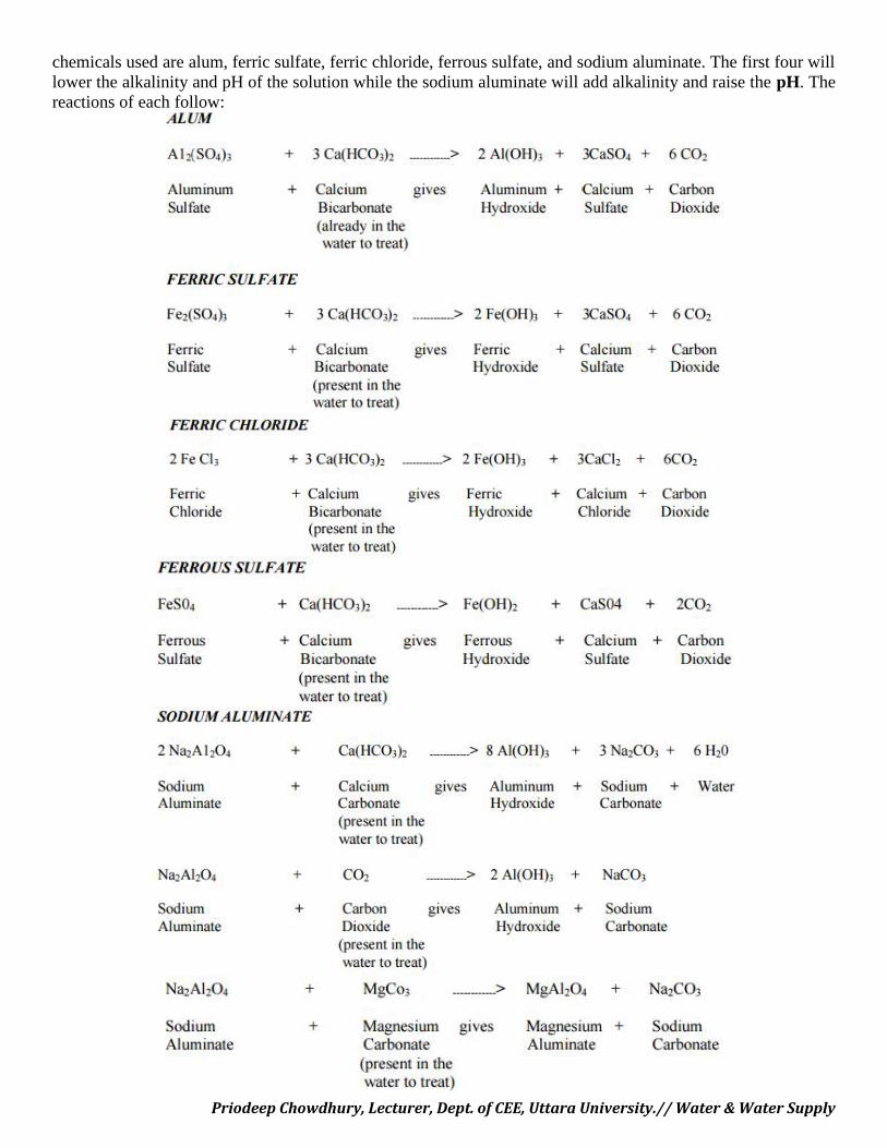
Priodeep Chowdhury, Lecturer, Dept. of CEE, Uttara University.// Water & Water Supply
chemicals used are alum, ferric sulfate, ferric chloride, ferrous sulfate, and sodium aluminate. The first four willlower the alkalinity and pH of the solution while the sodium aluminate will add alkalinity and raise the pH. Thereactions of each follow:
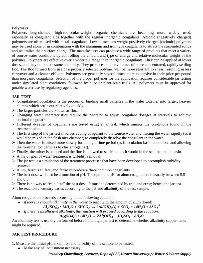
Priodeep Chowdhury, Lecturer, Dept. of CEE, Uttara University.// Water & Water Supply
PolymersPolymers--long-chained, high-molecular-weight, organic chemicals--are becoming more widely used,especially as coagulant aids together with the regular inorganic coagulants. Anionic (negatively charged)polymers are often used with metal coagulants. Low-to-medium weight positively charged (cationic) polymersmay be used alone or in combination with the aluminum and iron type coagulants to attract the suspended solidsand neutralize their surface charge. The manufacturer can produce a wide range of products that meet a varietyof source-water conditions by controlling the amount and type of charge and relative molecular weight of thepolymer. Polymers are effective over a wider pH range than inorganic coagulants. They can be applied at lowerdoses, and they do not consume alkalinity. They produce smaller volumes of more concentrated, rapidly settlingfloc. The floc formed from use of a properly selected polymer will be more resistant to shear, resulting in lesscarryover and a cleaner effluent. Polymers are generally several times more expensive in their price per poundthan inorganic coagulants. Selection of the proper polymer for the application requires considerable jar testingunder simulated plant conditions, followed by pilot or plant-scale trials. All polymers must be approved forpotable water use by regulatory agencies.
JAR TEST Coagulation/flocculation is the process of binding small particles in the water together into larger, heavier
clumps which settle out relatively quickly. The larger particles are known as floc. Changing water characteristics require the operator to adjust coagulant dosages at intervals to achieve
optimal coagulation. Different dosages of coagulants are tested using a jar test, which mimics the conditions found in the
treatment plant. The first step of the jar test involves adding coagulant to the source water and mixing the water rapidly (as it
would be mixed in the flash mix chamber) to completely dissolve the coagulant in the water. Then the water is mixed more slowly for a longer time period (as flocculation basin conditions and allowing
the forming floc particles to cluster together). Finally, the mixer is stopped and the floc is allowed to settle out, as it would in the sedimentation basin. A major goal of water treatment is turbidity removal. The jar test is a simulation of the treatment processes that have been developed to accomplish turbidity
removal Alum, ferrous sulfate, and ferric chloride are three common coagulants The best dose will also be a function of pH. The optimum pH for alum coagulation is usually between 5.5
and 6.5. There is no way to “calculate” the best dose. It must be determined by trial and error; hence, the jar test. The reaction chemistry varies according to the pH and alkalinity of the test sample.
Alum coagulation proceeds according to the following equation if there is enough alkalinity in the water to react with the amount of alum dosed:
Al2(SO4)3 • 14H2O + 6HCO3- ↔ 2Al(OH)3(s) + 6CO2 + 14H2O + 3SO4
-2
If there is insufficient alkalinity, the reaction will proceed according to the equation:Al2(SO4)3 • 14H2O ↔ 2Al(OH)3 + 3H2SO4 + 8H2O
An alkalinity test is usually performed before initiating a jar test to determine whether alkalinity supplementsmight be required.
JAR TEST PROCEDURE
1. Measure the initial pH, alkalinity, and turbidity of the sample to be tested. Make any pH adjustment necessary.
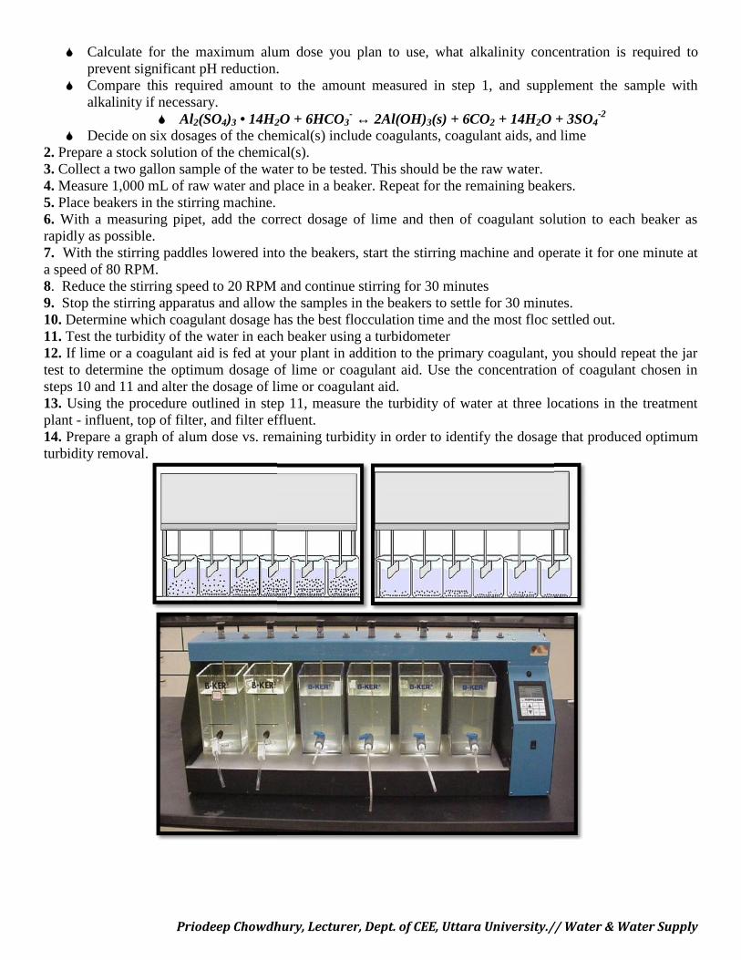
Priodeep Chowdhury, Lecturer, Dept. of CEE, Uttara University.// Water & Water Supply
Calculate for the maximum alum dose you plan to use, what alkalinity concentration is required toprevent significant pH reduction.
Compare this required amount to the amount measured in step 1, and supplement the sample withalkalinity if necessary.
Al2(SO4)3 • 14H2O + 6HCO3- ↔ 2Al(OH)3(s) + 6CO2 + 14H2O + 3SO4
-2
Decide on six dosages of the chemical(s) include coagulants, coagulant aids, and lime2. Prepare a stock solution of the chemical(s).3. Collect a two gallon sample of the water to be tested. This should be the raw water.4. Measure 1,000 mL of raw water and place in a beaker. Repeat for the remaining beakers.5. Place beakers in the stirring machine.6. With a measuring pipet, add the correct dosage of lime and then of coagulant solution to each beaker asrapidly as possible.7. With the stirring paddles lowered into the beakers, start the stirring machine and operate it for one minute ata speed of 80 RPM.8. Reduce the stirring speed to 20 RPM and continue stirring for 30 minutes9. Stop the stirring apparatus and allow the samples in the beakers to settle for 30 minutes.10. Determine which coagulant dosage has the best flocculation time and the most floc settled out.11. Test the turbidity of the water in each beaker using a turbidometer12. If lime or a coagulant aid is fed at your plant in addition to the primary coagulant, you should repeat the jartest to determine the optimum dosage of lime or coagulant aid. Use the concentration of coagulant chosen insteps 10 and 11 and alter the dosage of lime or coagulant aid.13. Using the procedure outlined in step 11, measure the turbidity of water at three locations in the treatmentplant - influent, top of filter, and filter effluent.14. Prepare a graph of alum dose vs. remaining turbidity in order to identify the dosage that produced optimumturbidity removal.
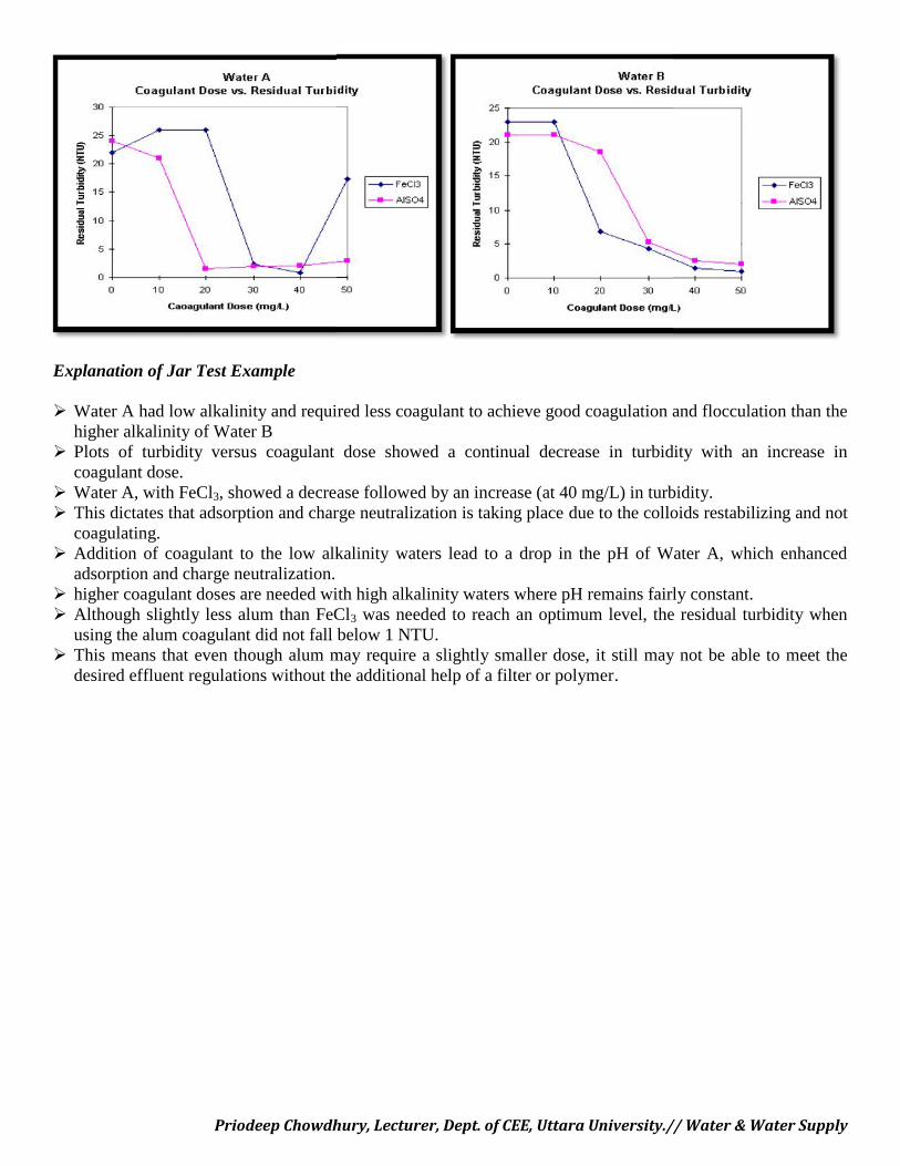
Priodeep Chowdhury, Lecturer, Dept. of CEE, Uttara University.// Water & Water Supply
Explanation of Jar Test Example
Water A had low alkalinity and required less coagulant to achieve good coagulation and flocculation than thehigher alkalinity of Water B
Plots of turbidity versus coagulant dose showed a continual decrease in turbidity with an increase incoagulant dose.
Water A, with FeCl3, showed a decrease followed by an increase (at 40 mg/L) in turbidity. This dictates that adsorption and charge neutralization is taking place due to the colloids restabilizing and not
coagulating. Addition of coagulant to the low alkalinity waters lead to a drop in the pH of Water A, which enhanced
adsorption and charge neutralization. higher coagulant doses are needed with high alkalinity waters where pH remains fairly constant. Although slightly less alum than FeCl3 was needed to reach an optimum level, the residual turbidity when
using the alum coagulant did not fall below 1 NTU. This means that even though alum may require a slightly smaller dose, it still may not be able to meet the
desired effluent regulations without the additional help of a filter or polymer.
Priodeep Chowdhury, Lecturer, Dept. of CEE, Uttara University.// Water & Water Supply
FILTRATION
After separating most floc, the water is filtered as the final step to remove remaining suspended particles andunsettled floc.
Electrolytic actionThe sand particles of filter media and the impurities in water carry electric charge of opposite nature, thereforethey attract each other and neutralize the charge of each other. After long use the electric charge of filter sand isexhausted, which is renewed by washing the filter bed.
Filter MaterialSand either coarse or fine, is generally used as filter media. The layers of sand may be supported on gravel,which permits the filtered water to move freely to the under drains and allow the wash water to move uniformlyupward.
Sand• The filter sand should generally be obtained from rock like quartzite and should have following
properties:• It should be free from dirt and other impurities• It should be of uniform size• It should be hard• If placed in hydrochloric acid for 24 hrs. it should not lose more than 5 % of weight.• Effective size of sand shall be
(a) 0.2 to 0.3 mm for slow sand filters(b) 0.35 to 0.6 mm for rapid sand filter
• Uniformity of SandIt is specified by the uniformity coefficient which is defined as the ratio between the sieve size in mmthrough which 60 % of the sample sand will pass to the effective size of the sand. Uniformity coefficient for slow sand filter = 2 to 3 1.3 to 1.7 for rapid sand filters
Gravel• The sand beds are supported on the gravel bed. The gravel used should be hard, durable, free from
impurities, properly rounded and should have a density of about 1600 kg/ m 3
• The gravel is placed in 5-6 layers having finest size on top.• Other material
Other materials which can be used are anthracite, Garnet, Sand or local material like coconut husks, ricehusks.
ClassificationsFilters are mainly classified based upon the rate of filtration as
1. Slow Sand Filter2. Rapid Sand Filter
(a) Rapid sand gravity filter(b) Pressure Filter
1. RAPID SAND FILTERS
Use relatively coarse sand and other granular media to remove particles and impurities that have beentrapped in a floc through the use of flocculation chemicals-typically salts of aluminium or iron.
Water and flocs flows through the filter medium under gravity or under pumped pressure Water moves vertically through sand which often has a layer of activated carbon or anthracite coal (a hard,
compact variety of mineral coal).
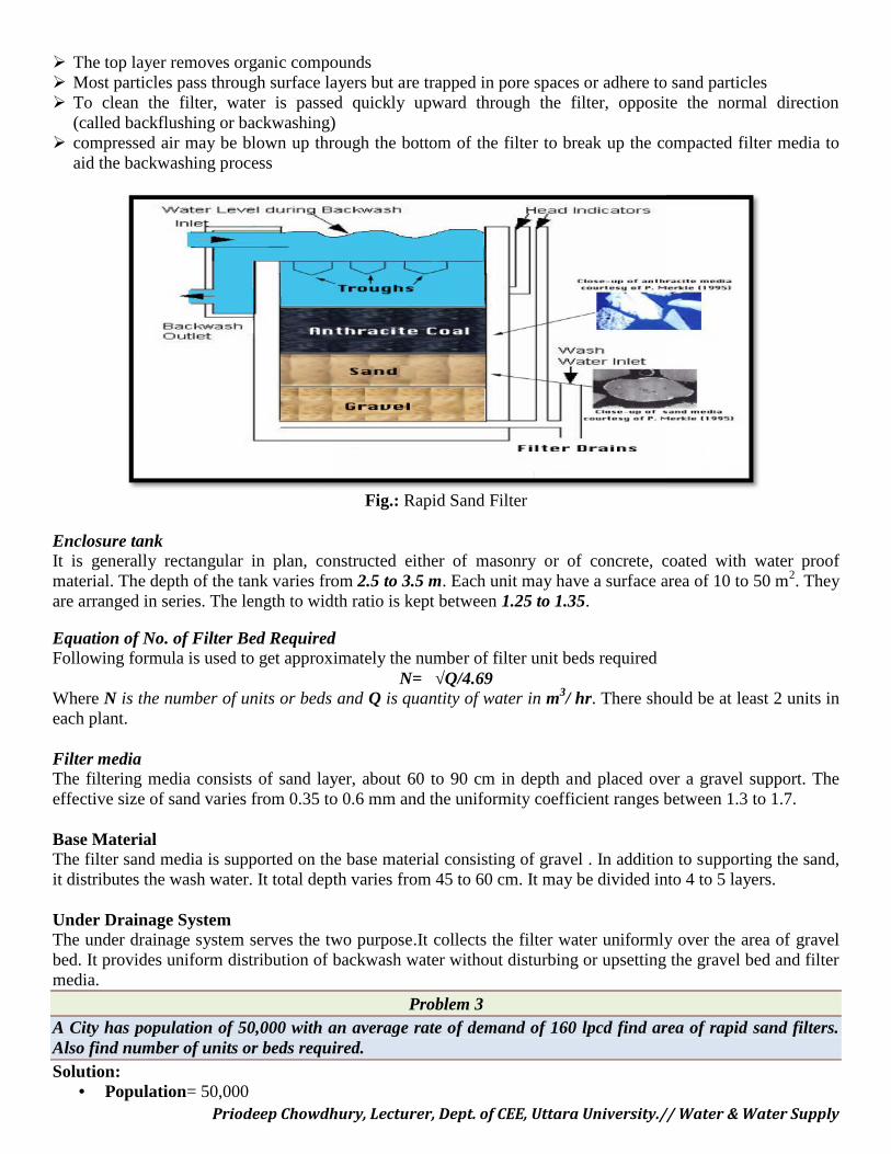
Priodeep Chowdhury, Lecturer, Dept. of CEE, Uttara University.// Water & Water Supply
The top layer removes organic compounds Most particles pass through surface layers but are trapped in pore spaces or adhere to sand particles To clean the filter, water is passed quickly upward through the filter, opposite the normal direction
(called backflushing or backwashing) compressed air may be blown up through the bottom of the filter to break up the compacted filter media to
aid the backwashing process
Fig.: Rapid Sand Filter
Enclosure tankIt is generally rectangular in plan, constructed either of masonry or of concrete, coated with water proofmaterial. The depth of the tank varies from 2.5 to 3.5 m. Each unit may have a surface area of 10 to 50 m2. Theyare arranged in series. The length to width ratio is kept between 1.25 to 1.35.
Equation of No. of Filter Bed RequiredFollowing formula is used to get approximately the number of filter unit beds required
N= √Q/4.69Where N is the number of units or beds and Q is quantity of water in m3/ hr. There should be at least 2 units ineach plant.
Filter mediaThe filtering media consists of sand layer, about 60 to 90 cm in depth and placed over a gravel support. Theeffective size of sand varies from 0.35 to 0.6 mm and the uniformity coefficient ranges between 1.3 to 1.7.
Base MaterialThe filter sand media is supported on the base material consisting of gravel . In addition to supporting the sand,it distributes the wash water. It total depth varies from 45 to 60 cm. It may be divided into 4 to 5 layers.
Under Drainage SystemThe under drainage system serves the two purpose.It collects the filter water uniformly over the area of gravelbed. It provides uniform distribution of backwash water without disturbing or upsetting the gravel bed and filtermedia.
Problem 3A City has population of 50,000 with an average rate of demand of 160 lpcd find area of rapid sand filters.Also find number of units or beds required.Solution:
• Population= 50,000Priodeep Chowdhury, Lecturer, Dept. of CEE, Uttara University.// Water & Water Supply
The top layer removes organic compounds Most particles pass through surface layers but are trapped in pore spaces or adhere to sand particles To clean the filter, water is passed quickly upward through the filter, opposite the normal direction
(called backflushing or backwashing) compressed air may be blown up through the bottom of the filter to break up the compacted filter media to
aid the backwashing process
Fig.: Rapid Sand Filter
Enclosure tankIt is generally rectangular in plan, constructed either of masonry or of concrete, coated with water proofmaterial. The depth of the tank varies from 2.5 to 3.5 m. Each unit may have a surface area of 10 to 50 m2. Theyare arranged in series. The length to width ratio is kept between 1.25 to 1.35.
Equation of No. of Filter Bed RequiredFollowing formula is used to get approximately the number of filter unit beds required
N= √Q/4.69Where N is the number of units or beds and Q is quantity of water in m3/ hr. There should be at least 2 units ineach plant.
Filter mediaThe filtering media consists of sand layer, about 60 to 90 cm in depth and placed over a gravel support. Theeffective size of sand varies from 0.35 to 0.6 mm and the uniformity coefficient ranges between 1.3 to 1.7.
Base MaterialThe filter sand media is supported on the base material consisting of gravel . In addition to supporting the sand,it distributes the wash water. It total depth varies from 45 to 60 cm. It may be divided into 4 to 5 layers.
Under Drainage SystemThe under drainage system serves the two purpose.It collects the filter water uniformly over the area of gravelbed. It provides uniform distribution of backwash water without disturbing or upsetting the gravel bed and filtermedia.
Problem 3A City has population of 50,000 with an average rate of demand of 160 lpcd find area of rapid sand filters.Also find number of units or beds required.Solution:
• Population= 50,000
Priodeep Chowdhury, Lecturer, Dept. of CEE, Uttara University.// Water & Water Supply
• Rate of water supply= 160• Maximum daily demand per day= 1.5 x 160 x 50000 = 12 x 10 6 lit /day• Assume rate of filtration = 4500 lit /hr./sq.m• Area of filter beds required= (12 x 10 6 )/ ( 24 x 4500 ) = 111.11 m 2
Number of filter beds can be found out by(i) Assuming area of one bed/ unit and then finding out the number of beds/ units required.(ii) By using the following eqn: N= √Q/4.69 Where, N= No of beds, Q= Quantity of water to be filtered in m3 /hr. Q= 12 MLD= 12 x 10 6 x 10 -3/ 24 = 500 m 3 /hr. N= √Q/4.69 = √ 500 / 4.69 = 5 units Area of each unit = 111.11/ 5 = 22.22 Assume L:B ratio as 1.3 ; L= 1.3 B; A= 1.3 B x B = 22.22= 1.3 B x B
B= 4.13 m; Therefore, L= 1.3 x 4.13 = 5.369 m
Provide B= 4.2 m and L= 5.4 m & Provide 6 such units one as stand by.
Efficiency and performance of Rapid Sand Filter
Turbidity• If the influent water does not have turbidity of more than 35 to 40 mg/lit. Since Coagulation and
sedimentation always precedes filtration the turbidity of water applied to filter is always less than 35 to40 mg/lit.
Bacterial Load• The rapid sand filters are less effective in removal of bacterial load as compare to slow sand filter. They
can remove 80 to 90 % of bacterial load.Color
• Rapid sand filter are very efficient in color removal. The intensity of color can be brought down below 3on cobalt scale.
Iron & Manganese• Rapid sand filter remove oxidized or oxidizing iron through it is less efficient in removing manganese
Taste & Odor• Unless special treatment such as activated carbon or pre chlorination is provided, rapid sand filters will
not ordinarily remove taste and odor,
Loss of Head & Negative HeadWhen a cleaned bed is put into operation, the loss of head through it will be small usually 15 to 30 cm. as thewater is filtered through it, impurities arrested by the filter media, due to which the loss of head goes onincreasing. A stage comes when the frictional resistance exceeds the static head above the sand bed, at thisstage, the lower portion of media and the under drainage system are under partial vacuum or negative head. Dueto the formation of negative head, dissolved gases and air are released filling the pores of the filter and theunder drainage system. In rapid sand filter permissible head loss will be 2.5 m to 3.5 mAdvantages Much higher flow rate than a slow sand filter; Requires relatively small land area Less sensitive to changes in raw water quality, e.g. turbidity requires less quantity of sandDisadvantages Requires greater maintenance than a slow sand filter. For this reason, it is not usually classed as an
"appropriate technology,".
Priodeep Chowdhury, Lecturer, Dept. of CEE, Uttara University.// Water & Water Supply
Generally ineffective against taste and odour problems. Produces large volumes of sludge for disposal. Requires on-going investment in costly flocculation reagents. treatment of raw water with chemicals is essential skilled supervision is essential cost of maintenance is more it cannot remove bacteria
2. SLOW SAND FILTERS Slow "artificial" filtration (a variation of bank filtration) to the ground, Water purification plant The filters are carefully constructed using graded layers of sand with the coarsest sand, along with
some gravel, at the bottom and finest sand at the top. Drains at the base convey treated water away for disinfection effective slow sand filter may remain in service for many weeks or even months produces water with a very low available nutrient level and low disinfectant levels Slow sand filters are not backwashed; they are maintained by having the top layer of sand scraped
off A 'large-scale' form of slow sand filter is the process of bank filtration in a riverbank. A slow sand filter unit consists of the following parts
Enclosure tank Filter media Base Material
Under drainage system
Inlet & Outlet arrangement Otherappurtenances
Enclosure TankIt consists of an open water tight rectangular tank made of concrete or masonary. The bed slope is 1 in 100 to 1in 200 towards the central drain. The depth of tank varies from 2.5 to 4 m. The plan area may vary from 100 to200 sq.m. depending upon the quantity of water treated.
Filter MediaThe filter media consist of sand layers about 90 to 110 cm in depth and placed over a gravel support. Theeffective size varies from 0.2 to 0.35 and uniformity coefficient varies from 2 to 3. Finer is the sand better is thequality of water.
Base MaterialThe filter media is supported on base size material consisting of 30 to 75 cm thick gravel of different sizes,placed in layers, generally 3 to 4 layers of 15 to 20 cm depth are used.
Under Drainage SystemThe base material are supported over the under drainage system which centrally collects the filter water. Thewater drainage system consists of a central drain collecting water from a number of lateral drains. The lateraldrains are open jointed pipe drains or perforated pipes of 7.5 to 10 cm dia spaced at 2 to 4 m centre to centre.
Inlet & OutletAn inlet chamber, is constructed for admitting the effluent from the plain sedimentation tank without disturbingthe sand layer of filter and to distribute it uniformly over filter bed
Other appurtenancesVarious appurtenances that are generally installed for efficient working are the device for ,easuring loss of headthrough filter media
• Controlling depth of water above the filter media.
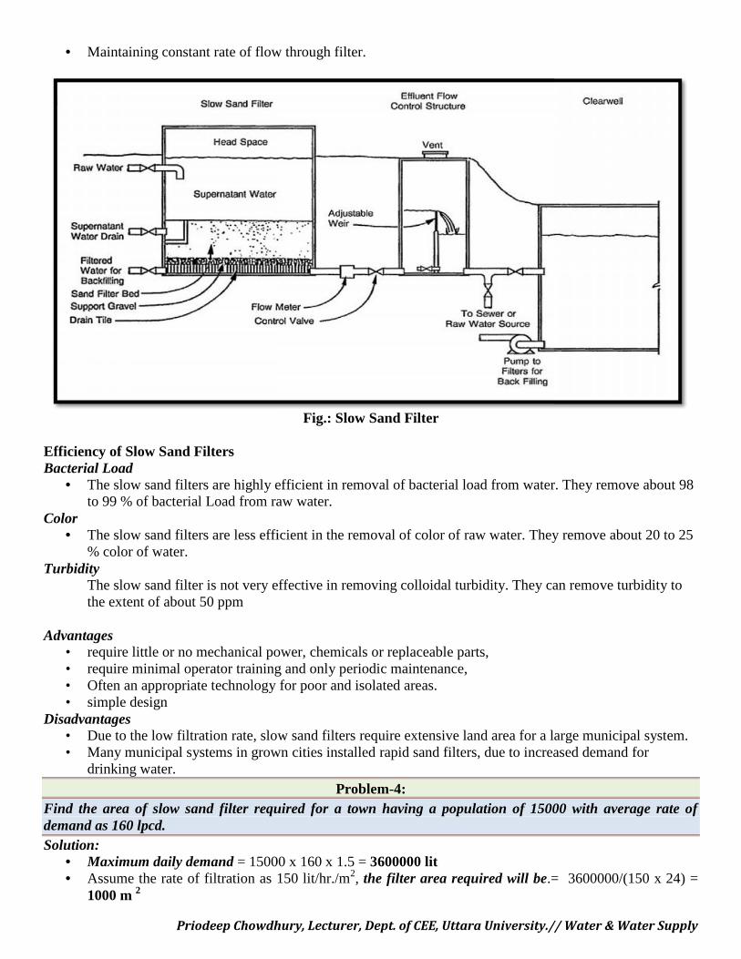
Priodeep Chowdhury, Lecturer, Dept. of CEE, Uttara University.// Water & Water Supply
• Maintaining constant rate of flow through filter.
Fig.: Slow Sand Filter
Efficiency of Slow Sand FiltersBacterial Load
• The slow sand filters are highly efficient in removal of bacterial load from water. They remove about 98to 99 % of bacterial Load from raw water.
Color• The slow sand filters are less efficient in the removal of color of raw water. They remove about 20 to 25
% color of water.Turbidity
The slow sand filter is not very effective in removing colloidal turbidity. They can remove turbidity tothe extent of about 50 ppm
Advantages• require little or no mechanical power, chemicals or replaceable parts,• require minimal operator training and only periodic maintenance,• Often an appropriate technology for poor and isolated areas.• simple design
Disadvantages• Due to the low filtration rate, slow sand filters require extensive land area for a large municipal system.• Many municipal systems in grown cities installed rapid sand filters, due to increased demand for
drinking water.Problem-4:
Find the area of slow sand filter required for a town having a population of 15000 with average rate ofdemand as 160 lpcd.Solution:
• Maximum daily demand = 15000 x 160 x 1.5 = 3600000 lit• Assume the rate of filtration as 150 lit/hr./m2, the filter area required will be.= 3600000/(150 x 24) =
1000 m 2
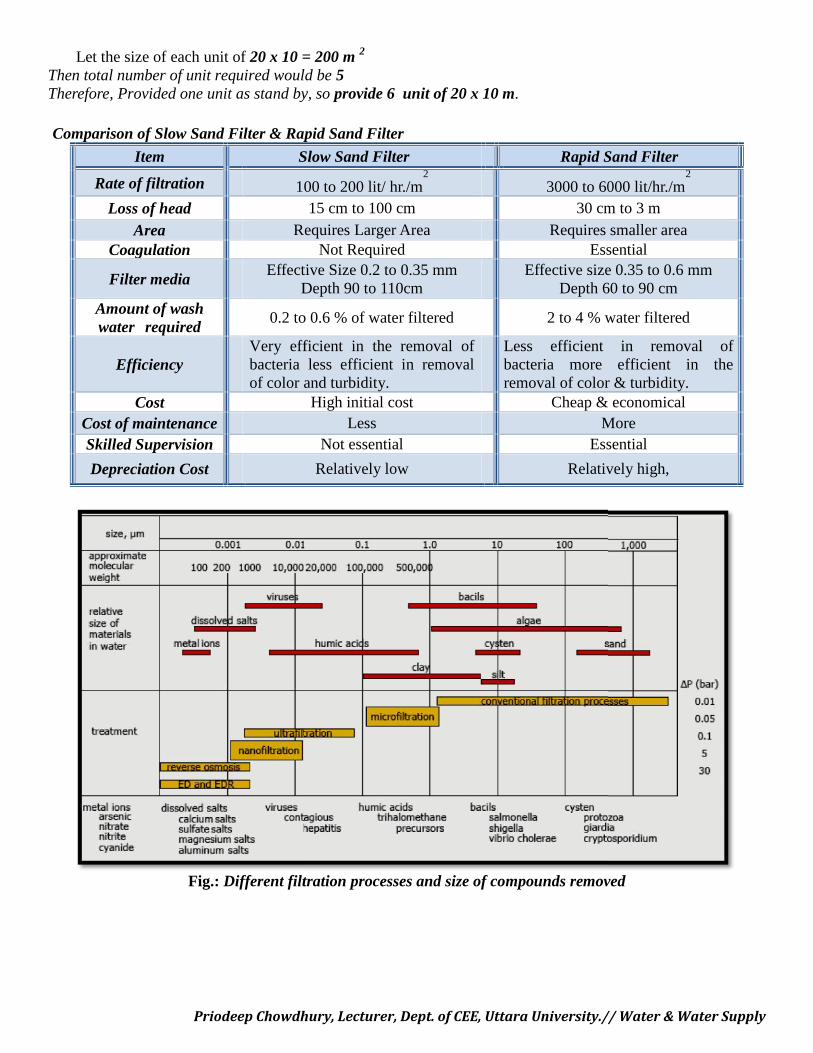
Priodeep Chowdhury, Lecturer, Dept. of CEE, Uttara University.// Water & Water Supply
Let the size of each unit of 20 x 10 = 200 m 2
Then total number of unit required would be 5Therefore, Provided one unit as stand by, so provide 6 unit of 20 x 10 m.
Comparison of Slow Sand Filter & Rapid Sand Filter
Item Slow Sand Filter Rapid Sand Filter
Rate of filtration 100 to 200 lit/ hr./m2
3000 to 6000 lit/hr./m2
Loss of head 15 cm to 100 cm 30 cm to 3 mArea Requires Larger Area Requires smaller area
Coagulation Not Required Essential
Filter mediaEffective Size 0.2 to 0.35 mm
Depth 90 to 110cmEffective size 0.35 to 0.6 mm
Depth 60 to 90 cmAmount of washwater required
0.2 to 0.6 % of water filtered 2 to 4 % water filtered
EfficiencyVery efficient in the removal ofbacteria less efficient in removalof color and turbidity.
Less efficient in removal ofbacteria more efficient in theremoval of color & turbidity.
Cost High initial cost Cheap & economicalCost of maintenance Less MoreSkilled Supervision Not essential Essential
Depreciation Cost Relatively low Relatively high,
Fig.: Different filtration processes and size of compounds removed
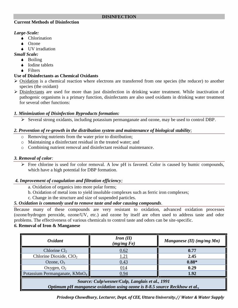
Priodeep Chowdhury, Lecturer, Dept. of CEE, Uttara University.// Water & Water Supply
DISINFECTIONCurrent Methods of Disinfection
Large-Scale: Chlorination Ozone UV irradiation
Small Scale: Boiling Iodine tablets Filters
Use of Disinfectants as Chemical Oxidants Oxidation is a chemical reaction where electrons are transferred from one species (the reducer) to another
species (the oxidant) Disinfectants are used for more than just disinfection in drinking water treatment. While inactivation of
pathogenic organisms is a primary function, disinfectants are also used oxidants in drinking water treatmentfor several other functions:
1. Minimization of Disinfection Byproducts formation: Several strong oxidants, including potassium permanganate and ozone, may be used to control DBP.
2. Prevention of re-growth in the distribution system and maintenance of biological stability;o Removing nutrients from the water prior to distribution;o Maintaining a disinfectant residual in the treated water; ando Combining nutrient removal and disinfectant residual maintenance.
3. Removal of color: Free chlorine is used for color removal. A low pH is favored. Color is caused by humic compounds,
which have a high potential for DBP formation.
4. Improvement of coagulation and filtration efficiency;a. Oxidation of organics into more polar forms;b. Oxidation of metal ions to yield insoluble complexes such as ferric iron complexes;c. Change in the structure and size of suspended particles.
5. Oxidation is commonly used to remove taste and odor causing compounds.Because many of these compounds are very resistant to oxidation, advanced oxidation processes(ozone/hydrogen peroxide, ozone/UV, etc.) and ozone by itself are often used to address taste and odorproblems. The effectiveness of various chemicals to control taste and odors can be site-specific.6. Removal of Iron & Manganese
Manganese (II) (mg/mg Mn)Iron (II)
(mg/mg Fe)Oxidant
0.770.62Chlorine Cl2
2.451.21Chlorine Dioxide, ClO2
0.88*0.43Ozone, O3
0.29014Oxygen, O2
1.920.94Potassium Permanganate, KMnO4
Source: Culp/wesner/Culp, Langlais et al., 1991Optimum pH manganese oxidation using ozone is 8-8.5 source Reckhow et al.,
Priodeep Chowdhury, Lecturer, Dept. of CEE, Uttara University.// Water & Water Supply
7. Prevention of algal growth in sedimentation basins and filters:Prechlorination will prevent slime formation on filters, pipes, and tanks, and reduce potential taste and odorproblems associated with such slimes.Factors affecting disinfection effectiveness Time pH Temperature Concentration of the disinfectant Concentration of organisms Nature of the disinfectant Nature of the organisms to be inactivated Nature of the suspending medium
C H L O R I N A T I O NC H L O R I N A T I O NMicroorganisms are harmful to human health; there are some that may cause diseases in humans. These
are called pathogens. Pathogens present in water can be transmitted through a drinking water distributionsystem, causing waterborne disease in those who consume it.
In order to combat waterborne diseases, different disinfection methods are used to inactivate pathogens.Along with other water treatment processes such as coagulation, sedimentation, and filtration, chlorinationcreates water that is safe for public consumption.
Chlorination is one of many methods that can be used to disinfect water. This method was first usedover a century ago, and is still used today. It is a chemical disinfection method that uses various types ofchlorine or chlorine-containing substances for the oxidation and disinfection of what will be the potable watersource.
The History of ChlorinationChlorine was first discovered in Sweden in 1744. At that time, people believed that odors from the water
were responsible for transmitting diseases. In 1835, chlorine was used to remove odors from the water, but itwasn't until 1890 that chlorine was found to be an effective tool for disinfecting; a way to reduce the amount ofdisease transmitted through water. With this new find, chlorination began in Great Britain and then expanded tothe United States in 1908 and Canada by 1917. Today, chlorination is the most popular method of disinfectionand is used for water treatment all over the world.
Why do we chlorinate our water?A large amount of research and many studies have been conducted to ensure success in new treatment
plants using chlorine as a disinfectant. A leading advantage of chlorination is that it has proven effective againstbacteria and viruses; however, it cannot inactivate all microbes. Some protozoan cysts are resistant to the effectsof chlorine.
In cases where protozoan cysts are not a major concern, chlorination is a good disinfection method touse because it is inexpensive yet effective in disinfecting many other possibly present contaminants. Thechlorination process is also fairly easy to implement, when compared to other water treatment methods. It is aneffective method in water emergency situations as it can eliminate an overload of pathogens relatively quickly.An emergency water situation can be anything from a filter breakdown to a mixing of treated and raw water.
How does chlorine inactivate microorganisms?Chlorine inactivates a microorganism by damaging its cell membrane. Once the cell membrane is
weakened, the chlorine can enter the cell and disrupt cell respiration and DNA activity (two processes that arenecessary for cell survival).
Priodeep Chowdhury, Lecturer, Dept. of CEE, Uttara University.// Water & Water Supply
When/How do we chlorinate our waters?Chlorination can be done at any time/point throughout the water treatment process - there is not one
specific time when chlorine must be added. Each point of chlorine application will subsequently control adifferent water contaminant concern, thus offering a complete spectrum of treatment from the time the waterenters the treatment facility to the time it leaves.
Pre-chlorination is when chlorine is applied to the water almost immediately after it enters the treatmentfacility.
In the pre-chlorination step, the chlorine is usually added directly to the raw water (the untreated waterentering the treatment facility), or added in the flash mixer (a mixing machine that ensures quick, uniformdispersion of the chlorine).
Chlorine is added to raw water to eliminate algae and other forms of aquatic life from the water so theywon’t cause problems in the later stages of water treatment.
Pre-chlorination in the flash mixer is found to remove tastes and odors, and control biological growththroughout the water treatment system, thus preventing growth in the sedimentation tanks (where solids areremoved from the water by gravity settling) and the filtration media (the filters through which the waterpasses after sitting in the sedimentation tanks).
The addition of chlorine will also oxidize any iron, manganese and/or hydrogen sulphide that are present, sothat they too can be removed in the sedimentation and filtration steps.
Disinfection can also be done just prior to filtration and after sedimentation. This would control thebiological growth, remove iron and manganese, remove taste and odors, control algae growth, and remove thecolor from the water. This will not decrease the amount of biological growth in the sedimentation cells.
Chlorination may also be done as the final step in the treatment process, which is when it is usuallydone in most treatment plants. The main objective of this chlorine addition is to disinfect the water and maintainchlorine residuals that will remain in the water as it travels through the distribution system.
Chlorinating filtered water is more economical because a lower CT value is required. This is acombination of the concentration (C) and contact time (T). The CT concept is discussed later on in this factsheet. By the time the water has been through sedimentation and filtration, a lot of the unwanted organisms havebeen removed, and as a result, less chlorine and a shorter contact time is required to achieve the sameeffectiveness. To support and maintain the chlorine residual, a process called re-chlorination is sometimes donewithin the distribution system. This is done to ensure proper chlorine residual levels are maintained throughoutthe distribution system.Chlorine demand, Residual chlorine & breakpoint chlorineAny type of chlorine that is added to water during the treatment process will result in the formation ofhypochlorous acid (HOCl) and hypochlorite ions (OCl-), which are the main disinfecting compounds inchlorinated water. More detail is provided later on in this fact sheet.
A Form of Chlorine + H2O → HOCl + OCl-
Of the two, hypochlorous acid is the most effective. The amount of each compound present in the water isdependent on the pH level of the water prior to addition of chlorine.
At lower pH levels, the hypochlorous acid will dominate. The combination of hypochlorous acid and hypochlorite ions makes up what is called ‘free chorine.’ Free chlorine has a high oxidation potential and is a more effective disinfectant than other forms of chlorine,
such as chloramines. Oxidation potential is a measure of how readily a compound will react with another. A high oxidation
potential means many different compounds are able to react with the compound. It also means that thecompound will be readily available to react with others.
Combined chlorine is the combination of organic nitrogen compounds and chloramines, which areproduced as a result of the reaction between chlorine and ammonia.
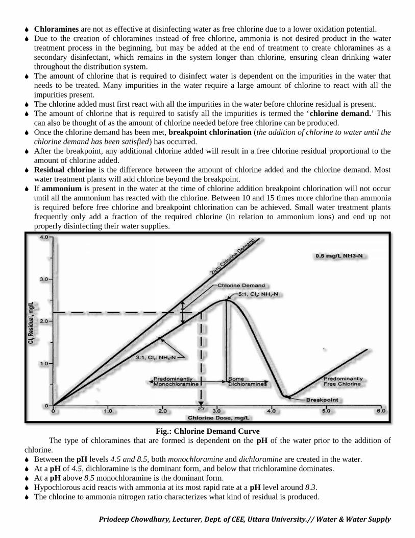
Priodeep Chowdhury, Lecturer, Dept. of CEE, Uttara University.// Water & Water Supply
Chloramines are not as effective at disinfecting water as free chlorine due to a lower oxidation potential. Due to the creation of chloramines instead of free chlorine, ammonia is not desired product in the water
treatment process in the beginning, but may be added at the end of treatment to create chloramines as asecondary disinfectant, which remains in the system longer than chlorine, ensuring clean drinking waterthroughout the distribution system.
The amount of chlorine that is required to disinfect water is dependent on the impurities in the water thatneeds to be treated. Many impurities in the water require a large amount of chlorine to react with all theimpurities present.
The chlorine added must first react with all the impurities in the water before chlorine residual is present. The amount of chlorine that is required to satisfy all the impurities is termed the ‘chlorine demand.’ This
can also be thought of as the amount of chlorine needed before free chlorine can be produced. Once the chlorine demand has been met, breakpoint chlorination (the addition of chlorine to water until the
chlorine demand has been satisfied) has occurred. After the breakpoint, any additional chlorine added will result in a free chlorine residual proportional to the
amount of chlorine added. Residual chlorine is the difference between the amount of chlorine added and the chlorine demand. Most
water treatment plants will add chlorine beyond the breakpoint. If ammonium is present in the water at the time of chlorine addition breakpoint chlorination will not occur
until all the ammonium has reacted with the chlorine. Between 10 and 15 times more chlorine than ammoniais required before free chlorine and breakpoint chlorination can be achieved. Small water treatment plantsfrequently only add a fraction of the required chlorine (in relation to ammonium ions) and end up notproperly disinfecting their water supplies.
Fig.: Chlorine Demand CurveThe type of chloramines that are formed is dependent on the pH of the water prior to the addition of
chlorine. Between the pH levels 4.5 and 8.5, both monochloramine and dichloramine are created in the water. At a pH of 4.5, dichloramine is the dominant form, and below that trichloramine dominates. At a pH above 8.5 monochloramine is the dominant form. Hypochlorous acid reacts with ammonia at its most rapid rate at a pH level around 8.3. The chlorine to ammonia nitrogen ratio characterizes what kind of residual is produced.
Priodeep Chowdhury, Lecturer, Dept. of CEE, Uttara University.// Water & Water Supply
Are there other uses for chlorine? The main purpose of chlorination is to disinfect water, but it also has many other benefits. Unlike some of the other disinfection methods like ozonation and ultraviolet radiation, chlorination is able to
provide a residual to reduce the chance of pathogen regrowth in water storage tanks or within the waterdistribution system.
At times, distribution systems can be a fair distance from the storage tanks and in dead end sections or wherewater is not used pathogens may re-grow if a proper (chlorine) residual is cannot be maintained in the treatedwater sent out for consumption. This results in poor water quality as well as slime and biofilms in thedistribution systems that will end up contaminating the clean, treated water being distributed.
Many government environmental bodies have set guidelines or standards for the amount of chlorine residualthat must be present at all points in the system.
In addition to providing residual, adding chlorine to water will also: oxidize iron, manganese, taste andodor compounds, remove color in the water, destroy hydrogen sulphide, and aid other water treatmentprocesses, such as sedimentation and filtration. Oxidizing soluble reduced iron and manganese will result inparticle formation as oxidized iron and manganese are not soluble in water.
Is chlorine all the same?The chlorination process involves adding chlorine to water, but the chlorinating product does not
necessarily have to be pure chlorine. Chlorination can also be carried out using chlorine-containing substances.Depending on the pH conditions required and the available storage options, different chlorine-containingsubstances can be used. The three most common types of chlorine used in water treatment are: chlorine gas,sodium hypochlorite, and calcium hypochlorite.
Chlorine GasChlorine gas is greenish yellow in color and very toxic. It is heavier than air and will therefore sink to
the ground if released from its container. It is the toxic effect of chlorine gas that makes it a good disinfectant,but it is toxic to more than just waterborne pathogens; it is also toxic to humans. It is a respiratory irritant and itcan also irritate skin and mucus membranes. Exposure to high volumes of chlorine gas fumes can cause serioushealth problems, including death. However, it is important to realize that chlorine gas, once entering the water,changes into hypochlorous acid and hypochlorite ions, and therefore its human toxic properties are not found inthe drinking water we consume.Chlorine gas is sold as a compressed liquid, which is amber in color. Chlorine, as a liquid, is heavier (moredense) than water. If the chlorine liquid is released from its container it will quickly return back to its gas state.Chlorine gas is the least expensive form of chlorine to use. The typical amount of chlorine gas required forwater treatment is 1-16 mg/L of water. Different amounts of chlorine gas are used depending on the quality ofwater that needs to be treated. If the water quality is poor, a higher concentration of chlorine gas will berequired to disinfect the water if the contact time cannot be increased.
When chlorine gas (Cl2) is added to the water (H2O), it hydrolyzes rapidly to produce hypochlorous acid(HOCl) and the hypochlorous acid will then dissociate into hypochlorite ions (OCl-) and hydrogen ions (H+).
Cl2 + H2O→ HOCl + H+ + OCl-
Because hydrogen ions are produced, the water will become more acidic (the pH of the water willdecrease). The amount of dissociation depends on the original pH of the water. If the pH of the water is below a6.5, nearly no dissociation will occur and the hypochlorous acid will dominate. A pH above 8.5 will see acomplete dissociation of chlorine, and hypochlorite ions will dominate. A pH between 6.5 and 8.5 will see bothhypochlorous acid and hypochlorite ions present in the water. Together, the hypochlorous acid and thehypochlorite ions are referred to as free chlorine. Hypchlorous acid is the more effective disinfectant, andtherefore, a lower pH is preferred for disinfection.
Calcium hypochlorite
Priodeep Chowdhury, Lecturer, Dept. of CEE, Uttara University.// Water & Water Supply
Calcium hypochlorite (CaOCl) is made up of the calcium salts of hypochlorous acid. It is produced bydissolving chlorine gas (Cl2) into a solution of calcium oxide (CaO) and sodium hydroxide (NaOH). Calciumhypochlorite is a white, corrosive solid that comes either in tablet form or as a granular powder. Calciumhypochlorite is very stable, and when packaged properly, large amounts can be purchased and stored untilneeded. The chemical is very corrosive however, and thus requires proper handling when being used to treatwater. Calcium hypochlorite needs to be stored in a dry area and kept away from organic materials. It cannot bestored near wood, cloth or petrol because the combination of calcium hypochlorite and organic material cancreate enough heat for an explosion. It must also be kept away from moisture because the tablets/granularpowder readily adsorb moisture and will form (toxic) chlorine gas as a result. Calcium hypochlorite has a verystrong chlorine odor – something that should be kept in mind when placing them in storage.When treating water, a lesser amount of calcium hypochlorite is needed than if using chlorine gas. Compared tothe 1-16 mg/L required with chlorine gas, only 0.5-5 mg/L of calcium hypochlorite is required. When calciumhypochlorite is added to water, hypochlorite and calcium ions are produced.
Ca(OCl)2 → Ca2+ + 2 OCl-
Instead of decreasing the pH like chlorine gas does, calcium hypochlorite increases the pH of the water(making the water less acidic). However, hypochlorous acid and hypochlorite concentrations are still dependenton the pH of the water; therefore by decreasing the pH of the water, hypochlorous acid will still be present inthe water. As a result, calcium hypochlorite and chlorine gas both produce the same type of residuals.
Sodium hypochloriteSodium hypochlorite (NaOCl) is made up of the sodium salts of hypochlorous acid and is a chlorine-
containing compound that can be used as a disinfectant. It is produced when chlorine gas is dissolved into asodium hydroxide solution. It is in liquid form, clear with a light yellow color, and has a strong chlorine smell.Sodium hypochlorite is extremely corrosive and must be stored in a cool, dark, and dry place. Sodiumhypochlorite will naturally decompose; therefore it cannot be stored for more than one month at a time. Of allthe different types of chlorine available for use, this is the easiest to handle.
The amount of sodium hypochlorite required for water treatment is much less than the other two formsof chlorine, with 0.2-2 mg of NaOCl / L of water being recommended. Like calcium hypochlorite, sodiumhypochlorite will also produce a hypochlorite ion, but instead of calcium ions, sodium ions are produced.NaOCl will also increase the pH of the water through the formation of hypochlorite ions. To obtainhypochlorous acid, which is a more effective disinfectant, the pH of the water should be decreased.
NaOCl → Na+ + OCl-
Is chlorine a sure way of eliminating pathogens?Chlorination has been proven to be very effective against bacteria and viruses. However, it cannot
disinfect all waterborne pathogens. Certain pathogens, namely protozoan cysts, are resistant to the effects ofchlorine. Cryptosporidium and Giardia, two examples of protozoan cysts, have caused great concern due to theserious illnesses they can cause. Cryptosporidium was the cause of the outbreak in North Battleford in 2001,and Milwaukee in April 1993. In raw water with high Giardia and Cryptosporidium levels, another method ofdisinfection should be considered. For more information on these protozoa, please read their self-titled factsheets in the public information section.Is chlorinating water ‘fool-proof’?
There are a number of factors that affect the disinfection process. Of these, the concentration or dosageof chlorine and the chlorine contact time (the time that chlorine is allowed to react with any impurities in thewater) are the most important factors.
Chlorine needs time to inactivate any microorganisms that may be present in the water being treated forhuman consumption. The more time chlorine is in contact with the microorganisms, the more effective theprocess will be. The contact time is the time from when the chlorine is first added until the time that the water isused or consumed.
Priodeep Chowdhury, Lecturer, Dept. of CEE, Uttara University.// Water & Water Supply
The same positive relationship is seen when considering the chlorine concentration. The higher theconcentration of chlorine, the more effective the water disinfection process will be. This relationship holds truebecause as the concentration increases, the amount of chlorine for disinfection is increased. Unlike therelationship between chlorine concentration and disinfection effectiveness, the chlorine concentration and thecontact time of chlorine with water show an inverse relationship. As the chlorine concentration increases, therequired water-chlorine contact time ultimately decreases. To determine the level of disinfection (D), a CTvalue can be calculated. This value is the product of the chlorine concentration (C) and contact time (T). Theformula is as follows: C*T=D. This concept shows that an increase in chlorine concentration (C) would requireless contact time to achieve the same desired level of disinfection. Another possibility would be an increase incontact time that would in turn require a lower chlorine concentration in order for the level of disinfection tostay the same.
The required CT value depends on several factors, including: the type of pathogens in the water, theturbidity of the water, the pH of the water and the temperature of the water. Turbidity is the suspended matter inthe water and the types of pathogens can range from bacteria like E.coli and Campylobacter to viruses includingHepatitis A. At lower temperatures, higher turbidity, or higher pH levels, the CT value (i.e. the disinfectionlevel) will have to be increased, but at lower turbidity, there is less suspended material in the water that willprevent contact of the disinfectant with the microorganisms, thus requiring a lower CT value. A higher watertemperature and a lower pH level will also allow for a lower CT value.
Impurity reactionsChlorine can react with a number of different substances. In raw water, there may be a number of
different impurities to react with the added chlorine, resulting in an increase of the chlorine demand. As a result,more chlorine will need to be added for the same level of inactivation. Some major impurities that may exist inwater include: dissolved iron, hydrogen sulphide, bromine, ammonia, nitrogen dioxide, and organic material. Insome cases, the result of chlorine reacting with impurities will increase the quality of the water (by eliminatingthe undesired elements), while in other cases; the chlorine-impurity reactions will create undesired side productsthat are harmful to human health. Chlorine will first react with inorganic impurities (dissolved iron, bromine,ammonia, etc.) before reacting with the organic compounds (dissolved organic material, bacteria, viruses, etc).
Iron, which will give water an undesirable metallic taste if present, is one of the inorganic compoundsthat will react with hypochlorous acid (the stronger form of free chlorine that is produced after pure chlorine isadded to water). By reacting with hypochlorous acid, the dissolved iron will go from a soluble state to aninsoluble state, as a precipitate is formed as a result of the reaction. The iron precipitate, in its insoluble state,can be removed by filtration process within the water treatment centre.
2 Fe2+ (liquid) + HOCl + 5H2O → 2 Fe(OH)3 (solid) + 5H+ + Cl-
Hypochlorous acid can also react with hydrogen sulphide (H2S), if it is present in the water being treated.Hydrogen sulfide is an undesirable impurity in water because it gives water an undesired smell. At levels below1 mg/L hydrogen sulphide generates a musty smell to the water, while at levels above 1 mg/L a rotten egg smellwill prevail. Hydrogen sulphide is also toxic. The hypochlorous acid and H2S reaction gives hydrochloric acidand sulphur ions as its products.
H2S + HOCl → H+ + Cl- + S + H2OBromine in the water can result in the production of undesired compounds. Bromine ions can react withhypochlorous acid to create hypobromous acid. Hypobromous acid also has disinfectant properties and is morereactive than hypochlorous acid. Hypochlorous acid or hypobromous acid will react with organic material in thewater and create halogenated by-products, such as trihalomethanes.
Br - + HOCl → HOBr + Cl-
Ammonia is a compound that may exist in the water. It is a nutrient to aquatic life, but one that willbecome toxic in high concentrations. Ammonia is produced as a result of decaying matter and thereforenaturally exists in the water; however, human activity also releases a large amount of ammonia into the water,which contributes to an increasing level of ammonia that may cause concern. Some ‘human activity sources’include: municipal wastewater treatment plants, agricultural releases, and industrial releases, such as pulp andpaper mills, mines, food processing, and fertilizer production. Reactions between ammonia and chlorine willproduce monochloramines, dichloramines, and trichloramines, which are collectively known as chloramines.
Priodeep Chowdhury, Lecturer, Dept. of CEE, Uttara University.// Water & Water Supply
These compounds are beneficial to the water treatment process as they have disinfection capacity, but they arenot as effective as chlorine although chloramines will last longer in the water.
Chlorine also reacts with phenols to produce monochlorophenols, dichlorophenols, or trichlorophenols,which cause taste and odour problem at low levels. At higher levels, chlorophenols are toxic and affect therespiration and energy storage process. Chlorophenols are mainly man-made compounds, but can be foundnaturally in animal wastes and decomposing organic material.
Are there health concerns with chlorinating water?Chlorine can be toxic not only for microorganisms, but for humans as well. To humans, chlorine is an
irritant to the eyes, nasal passages and respiratory system. Chlorine gas must be carefully handled because itmay cause acute health effects and can be fatal at concentrations as low as 1000 ppm. However, chlorine gas isalso the least expensive form of chlorine for water treatment, which makes it an attractive choice regardless ofthe health threat.
In drinking water, the concentration of chlorine is usually very low and is thus not a concern in acuteexposure. More of a concern is the long term risk of cancer due to chronic exposure to chlorinated water. This ismainly due to the trihalomethanes and other disinfection by-products, which are by-products of chlorination.Trihalomethanes are carcinogens, and have been the topic of concern in chlorinated drinking water. Chlorinatedwater has been associated with increased risk of bladder, colon and rectal cancer. In the case of bladder cancer,the risk may be doubled. Although there are concerns about carcinogens in drinking water, Health Canada'sLaboratory Centre for Disease Control says that the benefits of chlorinated water in controlling infectiousdiseases outweigh the risks associated with chlorination and would not be enough to justify its discontinuation.
Chlorination by-productsA number of different by-products can be produced from the reactions in the disinfection process. By-
products created from the reactions between inorganic compounds and chlorine are harmless and can be easilyremoved from the water by filtration. Other by-products, such as chloramines, are beneficial to the disinfectionprocess because they also have disinfecting properties. However, there are undesired compounds that may beproduced from chlorine reacting with organic matter. The compounds of most concern right now aretrihalomethanes (THMs) and haloacetic acids (HAAs). THMs and HAAs are formed by reactions betweenchlorine and organic material such as humic acids and fulvic acids (both generated from the decay of organicmatter) to create halogenated organics. A greater level of THM formation has been found in surface water orgroundwater influenced by surface water.
Trihalomethanes are associated with several types of cancer and are considered carcinogenic. Thetrihalomethane of most concern is chloroform, also called trichloromethane. It was once used as an anestheticduring surgery, but is now used in the process of making other chemicals. About 900 ppm of chloroform cancause dizziness, fatigue, and headaches. Chronic exposure may cause damage to the liver and kidneys. Otherharmful disinfection by-products are: trichloracetic acid, dichloroacetic acid, some haloacetonitriles, andchlorophenols.
Trichloracetic acid is produced commercially for use as a herbicide and is also produced in drinkingwater. This chemical is not classified as a carcinogen for humans, and there is limited information for animals.Dichloroacetic acid is an irritant, corrosive, and destructive against mucous membranes. This is also notcurrently classified as a human carcinogen. Haloacetonitriles were used as pesticides in the past, but are nolonger manufactured. They are produced as a result of a reaction between chlorine, natural organic matter, andbromide. Chlorophenols cause taste and odor problems. They are toxic, and when present in higherconcentrations, affect the respiration and energy storage process in the body.
Advantages and Disadvantages of Chloramine Use
Advantages Chloramines are not as reactive with organics as free chlorine in forming DBPs.
Priodeep Chowdhury, Lecturer, Dept. of CEE, Uttara University.// Water & Water Supply
The monochloramine residual is more stable and longer lasting than free chlorine or chlorine dioxide,thereby providing better protection against bacterial regrowth in systems with large storage tanks anddead end water mains. However excess ammonia in the network may cause biofilming.
Because chloramines do not tend to react with organic compounds, many systems will experience lessincidence of taste and odor complaints when using chloramines.
Chloramines are inexpensive. Chloramines are easy to make.
Disadvantages The disinfecting properties of chloramines are not as strong as other disinfectants, such as chlorine,
ozone, and chlorine dioxide. Chloramines cannot oxidize iron, manganese, and sulfides. When using chloramine as the secondary disinfectant, it may be necessary to periodically convert to free
chlorine for biofilm control in the water distribution system. Excess ammonia in the distribution system may lead to nitrification problems, especially in dead ends
and other locations with low disinfectant residual. Monochloramines are less effective as disinfectants at high pH than at low pH. Dichloramines have treatment and operation problems. Chloramines must be made on-site.
Restricted Water Use During Chlorination Do not drink the water and avoid all body contact. Water use should be minimized to assure that chlorine remains in the well during the minimum contact
period. If strong chlorine odors are detected, ventilate the affected area immediately, and minimize exposure to
the fumes. Avoid doing laundry, filling fish tanks, watering plants and using water for other purposes where the
chlorine may have an adverse effect.
DECHLORINATION
Dechlorination (removing residual chlorine from disinfected wastewater prior to discharge into theenvironment/sensitive aquatic waters or in a treated water to be lowered prior to distribution
The chlorinated water can be dosed with a substance that reacts with or accelerates the rate of decompositionof the residual chlorine.
Compounds that may perform this function include thiosulfate, hydrogen peroxide, ammonia,sulfite/bisulfite/sulfur dioxide, and activated carbon;
Hydrogen peroxide is not frequently used because it is dangerous to handle Only the latter two materials have been widely used for this purpose in water treatment (Snoeyink and
Suidan, 1975). (1) SO3
-2 + HOCl = SO4-2 + Cl- + H+
(2) SO3-2 + NH2Cl+ H20 = SO4
-2 + Cl- + NH4+
On a mass basis, 0.9 parts sulfur dioxide (or 1.46 parts NaHSO3 or 1.34 parts Na2S2O5) is required todechlorinate 1.0 part residual chlorine.
Advantages of Dechlorination Protects aquatic life from toxic effects of residual chlorine. Prevents formation of harmful chlorinated compounds in drinking water through reaction of residual chlorine
with water born organic materials.Disadvantages of Dechlorination Chemical dechlorination can be difficult to control when near zero levels of residual chlorine are required. Significant overdosing of sulfite can lead to sulfate formation, suppressed dissolved oxygen content, and
lower pH of the finished effluent.
Priodeep Chowdhury, Lecturer, Dept. of CEE, Uttara University.// Water & Water Supply
OO ZZ OO NN AA TT II OO NN
Primary purpose of Ozonation
Ozone is used in drinking water treatment for a variety of purposes including:• Disinfection;• Inorganic pollutant oxidation, including iron, manganese, and sulfide;• Organic micropollutant oxidation, including taste and odor compounds, phenolic pollutants, and some
pesticides; and• Organic macropollutant oxidation, including color removal, increasing the biodegradability of organic
compounds, DBP precursor control, and reduction of chlorine demand.
Pathogen Inactivation & Disinfection Efficacy of Ozone
• Ozone has a high germicidal effectiveness against a wide range of pathogenic organisms includingbacteria, protozoa, and viruses.
• Ozone cannot be used as a secondary disinfectant because the ozone residual decays too rapidly.• Ozone disinfection efficiency is not affected by pH although because of hydroxyl free radicals and rapid
decay, efficiency is the same but more ozone should be applied at high pH to maintain “C”.• Inactivation of bacteria by ozone is attributed to an oxidation reaction. The first site to be attacked
appears to be the bacterial membrane . Also, ozone disrupts enzymatic activity of bacteria• The first site of action for virus inactivation, particularly its proteins and RNA• aqueous ozone penetrates into the Giardia cysts wall and damages the plasma membranes, additional
penetration of ozone eventually affects the nucleus, and ribosome
Advantages of Ozone Use
Ozone is more effective than chlorine, chloramines, and chlorine dioxide for inactivation of viruses,Cryptosporidium, and Giardia.
Ozone oxidizes iron, manganese, and sulfides. Ozone can sometimes enhance the clarification process and turbidity removal. Ozone controls color, taste, and odors. One of the most efficient chemical disinfectants, ozone requires a very short contact time. In the absence of bromide, halogen-substitutes DBPs are not formed. Upon decomposition, the only residual is dissolved oxygen. Biocidal activity is not influenced by pH.
Disadvantages of Ozone Use
DBPs are formed, particularly by bromate and bromine-substituted DBPs, in the presence of bromide,aldehydes, ketones.
The initial cost of ozonation equipment is high. The generation of ozone requires high energy and should be generated on-site. Ozone is highly corrosive and toxic. Biologically activated filters are needed for removing assimilable organic carbon and biodegradable DBPs. Ozone decays rapidly at high pH and warm temperatures. Ozone provides no residual. Ozone requires higher level of maintenance and operator skill
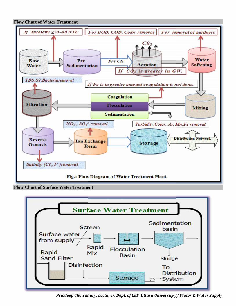
Priodeep Chowdhury, Lecturer, Dept. of CEE, Uttara University.// Water & Water Supply
Flow Chart of Water Treatment
Flow Chart of Surface Water Treatment
Priodeep Chowdhury, Lecturer, Dept. of CEE, Uttara University.// Water & Water Supply
Flow Chart of Water Treatment
Flow Chart of Surface Water Treatment
Priodeep Chowdhury, Lecturer, Dept. of CEE, Uttara University.// Water & Water Supply
Flow Chart of Water Treatment
Flow Chart of Surface Water Treatment
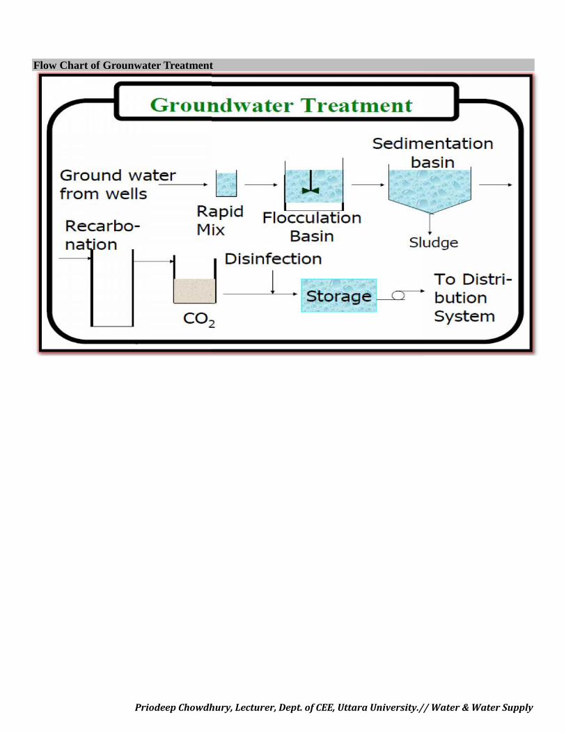
Priodeep Chowdhury, Lecturer, Dept. of CEE, Uttara University.// Water & Water Supply
Flow Chart of Grounwater Treatment
Priodeep Chowdhury, Lecturer, Dept. of CEE, Uttara University.// Water & Water Supply
Flow Chart of Grounwater Treatment
Priodeep Chowdhury, Lecturer, Dept. of CEE, Uttara University.// Water & Water Supply
Flow Chart of Grounwater Treatment
Priodeep Chowdhury, Lecturer, Dept. of CEE, Uttara University.// Water & Water Supply
IM P O R TA N T QU E S T IO N S :1. Name the water treatment methods.2. Draw the flow chart of water treatment plant.3. Draw the flow chart of Surface Water & Ground-water Treatment.4. Write Short Notes on/ Describe the following terms:
I. PresedimentationII. Screening
III. Primary SedimentationIV. Sedimentation BasinsV. Ion Exchange
VI. Taste, Odor & Dissolved OxygenRemoval
VII. Water SofteningVIII. Coagulation
IX. FlocculationX. Water Disinfection
XI. ChlorinationXII. CO2 , H2S, CH4 Removal
XIII. OzonationXIV. Iron & Manganese RemovalXV. Rapid Sand Filter, RSF & Slow Sand
Filter, SSFXVI. Dechlorination
XVII. AerationXVIII. Demineralisation = Deionization
XIX. Jar TestXX. Activated Carbon as Absorbent
XXI. Chlorine demand, Residual chlorine &breakpoint chlorine
XXII. Restricted water use during chlorination
5. Why do we chlorinate our water?6. How does chlorine inactivate microorganisms?7. When/How do we chlorinate our waters?8. Describe Chlorine demand, Residual chlorine & breakpoint chlorine with necessarygraphical explanation.9. Describe the types of Aerators.10. Describe the types of Sedimentation Basins.11. Describe the design prelimineries for Sedimentation Basin.12. Write down the advantages & disadvantages of Chlorination, Dechlorination & Ozonation.13. Draw the cross section of RSF & SSF.14. Write down the advantages & disadvantages of RSF & SSF.15. Describe the primary purpose of Ozonation.16. Describe the Pathogen Inactivation & Disinfection Efficacy of Ozone.17. Explain: Why Jar Test is done? Describe the Jar Test Procedure.18. Is chlorine a sure way of eliminating pathogens?19. Are there other uses for chlorine? - Briefly Explain.20. Write down the advantages & disadvantages of Chloramine use.21. Describe the Efficiency and performance of Rapid Sand Filter & Slow Sand Filter.22. Write down the comparison between RSF & SSF.24. All the mathematical problems.


