Download - PREFERRED INSTRUMENTS

• Control VFDs to Save Electricity • Communicate Important Plant Information• Improve Water Quality and Extend Boiler Life
PREFERRED INSTRUMENTSA Division of Preferred Utilities Manufacturing Corporation
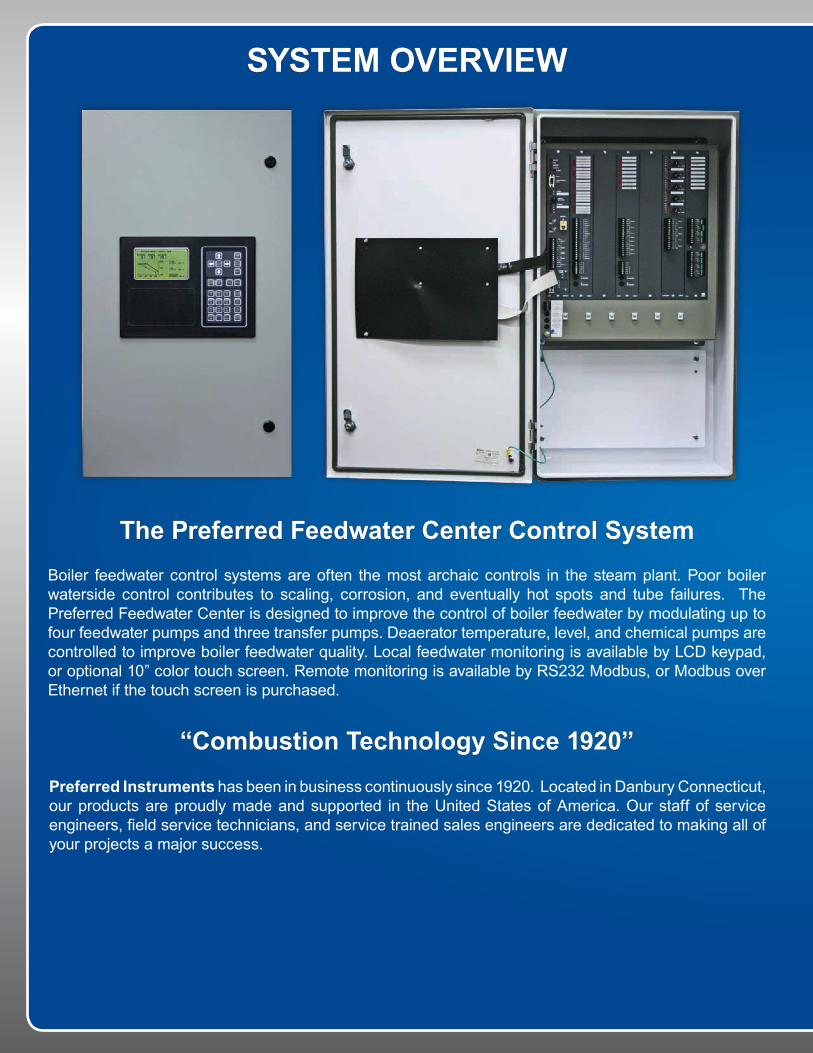
Preferred Instruments has been in business continuously since 1920. Located in Danbury Connecticut, our products are proudly made and supported in the United States of America. Our staff of service engineers, field service technicians, and service trained sales engineers are dedicated to making all of your projects a major success.
Boiler feedwater control systems are often the most archaic controls in the steam plant. Poor boiler waterside control contributes to scaling, corrosion, and eventually hot spots and tube failures. The Preferred Feedwater Center is designed to improve the control of boiler feedwater by modulating up to four feedwater pumps and three transfer pumps. Deaerator temperature, level, and chemical pumps are controlled to improve boiler feedwater quality. Local feedwater monitoring is available by LCD keypad, or optional 10” color touch screen. Remote monitoring is available by RS232 Modbus, or Modbus over Ethernet if the touch screen is purchased.
SYSTEM OVERVIEW
The Preferred Feedwater Center Control System
“Combustion Technology Since 1920”

FEEDWATER CENTER BENEFITSENSURE CONSISTENT FEEDWATER TEMPERATURE AND PRESSURE
MAINTAIN PROPER OXYGEN REMOVAL AT ALL FIRING RATES
INTEGRATED MODEM FOR OFF-SITE MONITORING
FIELD ADJUSTABLE PARAMETERS
PLUG-IN OPTION BOARDS AVAILABLE FOR INSTANT FIELD UPGRADES
Deaerator Control• Ensures a steady flow of properly treated boiler feedwater by precisely controlling deaerator
temperature, pressure, and level. • Secure a continuous supply of make up water to the deaerator by controlling surge tank level. • Deaerator control allows the user to minimize deaerator venting and boiler blowdown and improve
plant efficiency.• Maintains consistent deaerator temperature and pressure to stabilize steam plant operation.
Pump Control• Ensures a continuous supply of boiler feedwater with start / stop and PID modulating control of up
to four boiler feed pumps, three transfer pumps, and a chemical injection pump.• Saves electricity with PID control of feed pump and transfer pump variable frequency drives
matching pump speed to the actual current load.• Increase reliability. In headered mode, pumps are automatically start / stopped to guarantee the
correct number of pumps are always running.
Automation• The Feedwater Center operates independently, reassuring proper feedwater conditions to the
boilers, even in the event of a pump failure.• The automatic rotation of lead and lag pumps allows for even wear of pumps without operator
input.
Plant Monitoring• Instantly see the status of all controlled variables from the LCD screen.• Alarm indications quickly alert plant personnel to upset conditions providing corrected before
interrupting boiler operations.• Trend screens help diagnose problems so stationary engineers can take corrective action.• RS232 Modbus interface allows remote viewing of important Feedwater Center variables. Remote
control of certain inputs helps automate plant operations for unmanned or remote boiler rooms.
Optional Color Touch Screen• 10” operator color touch screen provides vivid graphical representations of boiler plant equipment,
trending of plant parameters, and alarm annunciation.• Touch screens also provide Modbus over Ethernet communications.

TOUCH SCREEN OPTIONSEase of UseThe Feedwater Center is easy to set up by parameter selection. No programming is required. The system is easily customized to the particular equipment at each plant. The controller is based on the industry-proven Plant Wide Controller and the same color touch screen used for all Preferred control systems. Below are some examples of the interactive touch screens. There are over 20 custom screens.
Tuning PageTuning pages allow the user to view control loops for tuning purposes. Historical data is saved to a compact flash card and can be viewed through a PC.
Touch Screen OverviewThe optional 10” Operator Interface Terminal (OIT) touch screen provides graphical representation of current system status. Pump status, level indication, and valve position are all readily available on the system overview page.
Setup ParametersAll parameters are available through the setup pages on the touch screen. System features and control logic are adjusted depending on the initial setup parameters.
Alarm PageThe alarm and events screen lists all current alarms and all recent control events. This screen helps diagnose boiler before they impact boiler operation.

MANUFACTURING
ConstructionThe Feedwater Center is housed in a NEMA 4 enclosure for installation in potentially wet areas. This wall-mount enclosure can be mounted on the side of a boiler, or on a wall in a central location. Only 120 VAC (12 amp) power is required.
DesignWe boast a fully staffed engineering department ready to provide drawings, panel wiring drawings, sequence of operations, SAMA drawings, and O&M manuals. Our engineering department uses state-of-the-art engineering tools to streamline the engineering process.
Quality AssuranceThe unique types of problems that we solve for our customers require the implementation of an effective quality assurance program. Our record of strict adherence to established quality standards and industry practices has made us the leader in our field.

FULL CONTROL SCHEMATIC
deaerator tank
surge tank
Boiler 1 Run (Boiler Limits, One per Boiler)
Surge Tank Make Up Water Valve
Surge Tank Low Level Sensor
DA Tank Level Control Valve
DA Tank Level
To Boilers (Header Piped or Optional Per Boiler Set Up)
DA Tank PSI
Chemical Feed Valve
Feedwater Pumps
Transfer Pumps
Condensate Return Line Temperature
DA Tank Temperature
FW H
eade
r PSI
Proof of FlowBoiler Feedwater Pump ONBoiler Feedwater Pump Speed Control
Proof of FlowTransfer Pump ONTransfer Pump Speed Control
DA Tank PSI Control Valve
DA Tank Low Level Sensor
PT LT TELS
PS
Chem
ical F
eed
Make Up Water Line
Water Softener
Typical Per Pump
Typical Per Pump
Condensate Return Line Flow
Steam Header Pressure
LS
Surge Tank Level
LTPT FT
Make Up Water PSIMake Up Water Flow
Soft Water Regen
ApplicationThe Feedwater Center Model JC-FWC-FC includes all available features and capabilities required to control feedwater delivery systems including DA level and pressure control, surge tank level control, transfer pump control, feedwater pump control, chemical feed pump control and water softener regeneration.

ORDERING INFORMATION
*Steam PSI transmitter must be scaled similar to the Feedwater PSI transmitter**HOA switches provided on -NS and -NVS models
JC-FWC-xxx -FC -NV -NS -NVS Field Device
Digital InputsFW Pump Running 4 4 4 4 120 VAC - (e.g. current sensing relay)Boiler Running/Call For Water 4 4 4 4 120 VAC - BLR Run/Drum Level SwitchTP Pump Running 3 3 120 VAC - CSR/Aux Contact MotorstarterDA Low Level Cutoff Switch 1 1 1 1 120 VAC - Level SwitchST Low Level Cutoff Switch 1 1 1 120 VAC - Level SwitchWater Softener Alarm 1 1 1 1 120 VAC - Contact From SoftenerDisable 1 1 1 1 120 VAC - Contact From BAS
Analog InputsDA Level 1 1 1 1 4-20mA Level Transmitter
DA Temperature 1 1 1 Thermowell (part numbers 70610, 70611)
DA PSI 1 1 1 4-20mA PSI Transmitter (part number 7060X)FW Header PSI 1 1 1 1 4-20mA PSI Transmitter (part number 7060X)Steam PSI 1 1 1 4-20mA PSI Transmitter (part number 7060X)*Makeup Flow 1 1 1 4-20mA Flow MeterMakeup Pressure 1 1 1 4-20mA PSI Transmitter (part number 7060X)Condensate Return Temperature 1 1 1 Thermowell (part numbers 70610, 70611)Condensate Return Flow 1 1 1 4-20mA Flow MeterSurge Tank Level 1 1 4-20mA Level Transmitter
Digital OutputsFW Pump Start 4 4 4** 4** Dry Contact (close to start)TP Pump Start 3 3 Dry Contact (close to start)Water Softener Regen Cycle 1 1 1** Dry Contact (close to start)
Analog OutputsFW Pump Speed 4 4 4-20mA OutputTP Pump Speed 3 4-20mA OutputST MU Water Valve 1 1 4-20mA OutputChem Feed Pump 1 1 1 4-20mA OutputDA PSI Control Valve 1 1 1 4-20mA OutputDA Level Control Valve 1 1 1 4-20mA Output
The Preferred Feedwater Center is available in four models, each with different capabilities. To select the correct model for each application, consult the hardware configurations.
Model Number Description PWC Hardware
Configuration
JC-FWC-FC Full Control PWCN4-CDROOOA
JC-FWC-FC-OIT Full Control WITH 10” OIT PWCN4-CDROOOA
JC-FWC-NV No VSD Control ( on-off control of pumps) PWCN4-CDROxxA
JC-FWC-NV-OIT No VSD Control ( on-off control of pumps) with 10” OIT PWCN4-CDROxxA
JC-FWC-NS No Surge Tank/Transfer Pumps PWCN4-CDHOOxA
JC-FWC-NS-OIT No Surge Tank/Transfer Pumps with 10” OIT PWCN4-CDHOOxA
JC-FWC-NVS No VSDs and no Surge Tank/Transfer Pump PWCN4-CDHxxxx
JC-FWC-NVS-OIT No VSDs and no Surge Tank/Transfer Pump with 10” OIT PWCN4-CDHxxxx

PREFERRED INSTRUMENTSA DIVISION OF PREFERRED UTILITIES
31-35 SOUTH STREETDANBURY, CT 06810
T: (203) 743-6741F: (203) 798-7313
WWW.PREFERRED-MFG.COM
CS-FWC-1
Represented By:
© Preferred Utilities Manufacturing Corporation PREFERREDENGINEERING
MADE IN THE U.S.A.


