
PRE-FEASIBILITY REPORT
For
INTEGRATED PROJECT FORMODERNIZATION OF
KUMARASAMY RAJA NAGAR CEMENT PLANTFOR INCREASE OF CLINKER PRODUCTION
FROM 2.8 MTPA TO 3.185 MTPABY UPGRADATION OF LINE – I &
OPTIMUM UTILIZATION OF LINE - IIAND
INSTALLATION OF 6 MW TURBO GENERATORAt
KSR Nagar, Mandal Jaggayyapet, District Krishna, AndhraPradesh
Of
THE RAMCO CEMENTS LIMITED(FORMERLY KNOWN AS MADRAS CEMENTS LTD)
(An ISO 9001:2008, ISO 14001:2004 and IS 18001:2007 Company)
Works:KSR Nagar, Jaggayyapet Mandal,
Krishna District, Andhra Pradesh – 521457Tel: 08654-224400 to 09
Regd. & Corporate office:Auras Corporate Centre, 98-A Dr.Radhakrishnan Salai
Mylapore, Chennai - 600 004
Table of Contents
1. Executive Summary 01
2. Introduction 03
3. Project Description 10
4. Site Analysis 18
5. Planning Brief 23
6. Proposed infrastructure 24
7. Rehabilitation and resettlement (R & R) Plan 25
8. Project schedule & Cost Estimates 26
9. Analysis of proposal (Final Recommendations) 27
Annexure
Annexure-1 (a) - MoEF EC Letter No. J-11011/403/2006- IA II (I)dated 9th June, 2009
Figure
Figure-1 Location MapFigure-2 Cement Plant LayoutFigure-3 Topographical Map
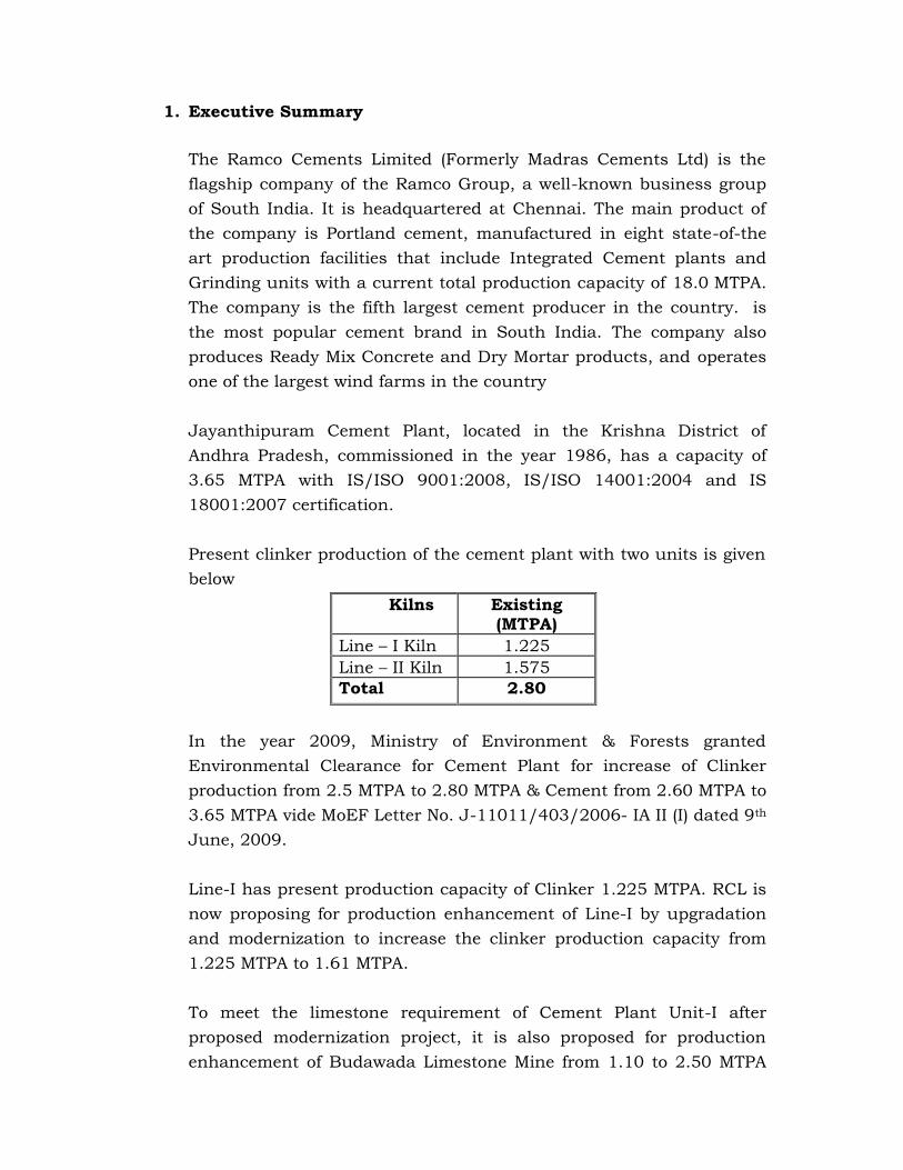
1. Executive Summary
The Ramco Cements Limited (Formerly Madras Cements Ltd) is theflagship company of the Ramco Group, a well-known business groupof South India. It is headquartered at Chennai. The main product ofthe company is Portland cement, manufactured in eight state-of-theart production facilities that include Integrated Cement plants andGrinding units with a current total production capacity of 18.0 MTPA.The company is the fifth largest cement producer in the country. isthe most popular cement brand in South India. The company alsoproduces Ready Mix Concrete and Dry Mortar products, and operatesone of the largest wind farms in the country
Jayanthipuram Cement Plant, located in the Krishna District ofAndhra Pradesh, commissioned in the year 1986, has a capacity of3.65 MTPA with IS/ISO 9001:2008, IS/ISO 14001:2004 and IS18001:2007 certification.
Present clinker production of the cement plant with two units is givenbelow
Kilns Existing(MTPA)
Line – I Kiln 1.225Line – II Kiln 1.575Total 2.80
In the year 2009, Ministry of Environment & Forests grantedEnvironmental Clearance for Cement Plant for increase of Clinkerproduction from 2.5 MTPA to 2.80 MTPA & Cement from 2.60 MTPA to3.65 MTPA vide MoEF Letter No. J-11011/403/2006- IA II (I) dated 9th
June, 2009.
Line-I has present production capacity of Clinker 1.225 MTPA. RCL isnow proposing for production enhancement of Line-I by upgradationand modernization to increase the clinker production capacity from1.225 MTPA to 1.61 MTPA.
To meet the limestone requirement of Cement Plant Unit-I afterproposed modernization project, it is also proposed for productionenhancement of Budawada Limestone Mine from 1.10 to 2.50 MTPA

without increase in mining lease area. The proposal is submitted toMoEF separately for necessary environmental clearance.
To meet the additional power requirement, it is proposed to install 6MW Turbine Generator. The boilers of installed capacity of 2 X 90 TPHare presently operated at 2 X 76 TPH. To meet the steam requirementof the proposed 6 MW Turbine Generator, the installed boilers will beoperated at 2 X 86 TPH capacity.
Modernization of the cement plant will be takenup within the existingcement plant complex. No additional land will be acquired. Greenbeltis existing in about 128 ha.
Water requirement of the cement plant (including 6 MW proposedpower generation) will increase by additional 430 m3/day, which willbe met from mine pit.
Coal requirement of cement plant (including 6 MW powergeneration)will increase by additional 0.123 MTPA.
Full-fledged colony with necessary infrastructure is existing. Theexisting colony is adequate and no additional quarters are proposed.
No solid waste generation from the cement plant.
The estimated total cost of the project is Rs. 100 Crore.
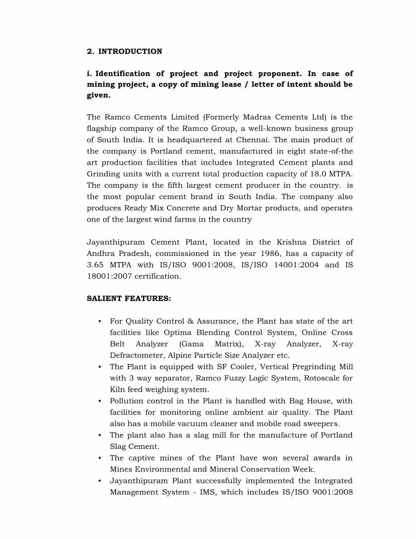
2. INTRODUCTION
i. Identification of project and project proponent. In case ofmining project, a copy of mining lease / letter of intent should begiven.
The Ramco Cements Limited (Formerly Madras Cements Ltd) is theflagship company of the Ramco Group, a well-known business groupof South India. It is headquartered at Chennai. The main product ofthe company is Portland cement, manufactured in eight state-of-theart production facilities that includes Integrated Cement plants andGrinding units with a current total production capacity of 18.0 MTPA.The company is the fifth largest cement producer in the country. isthe most popular cement brand in South India. The company alsoproduces Ready Mix Concrete and Dry Mortar products, and operatesone of the largest wind farms in the country
Jayanthipuram Cement Plant, located in the Krishna District ofAndhra Pradesh, commissioned in the year 1986, has a capacity of3.65 MTPA with IS/ISO 9001:2008, IS/ISO 14001:2004 and IS18001:2007 certification.
SALIENT FEATURES:
• For Quality Control & Assurance, the Plant has state of the artfacilities like Optima Blending Control System, Online CrossBelt Analyzer (Gama Matrix), X-ray Analyzer, X-rayDefractometer, Alpine Particle Size Analyzer etc.
• The Plant is equipped with SF Cooler, Vertical Pregrinding Millwith 3 way separator, Ramco Fuzzy Logic System, Rotoscale forKiln feed weighing system.
• Pollution control in the Plant is handled with Bag House, withfacilities for monitoring online ambient air quality. The Plantalso has a mobile vacuum cleaner and mobile road sweepers.
• The plant also has a slag mill for the manufacture of PortlandSlag Cement.
• The captive mines of the Plant have won several awards inMines Environmental and Mineral Conservation Week.
• Jayanthipuram Plant successfully implemented the IntegratedManagement System - IMS, which includes IS/ISO 9001:2008
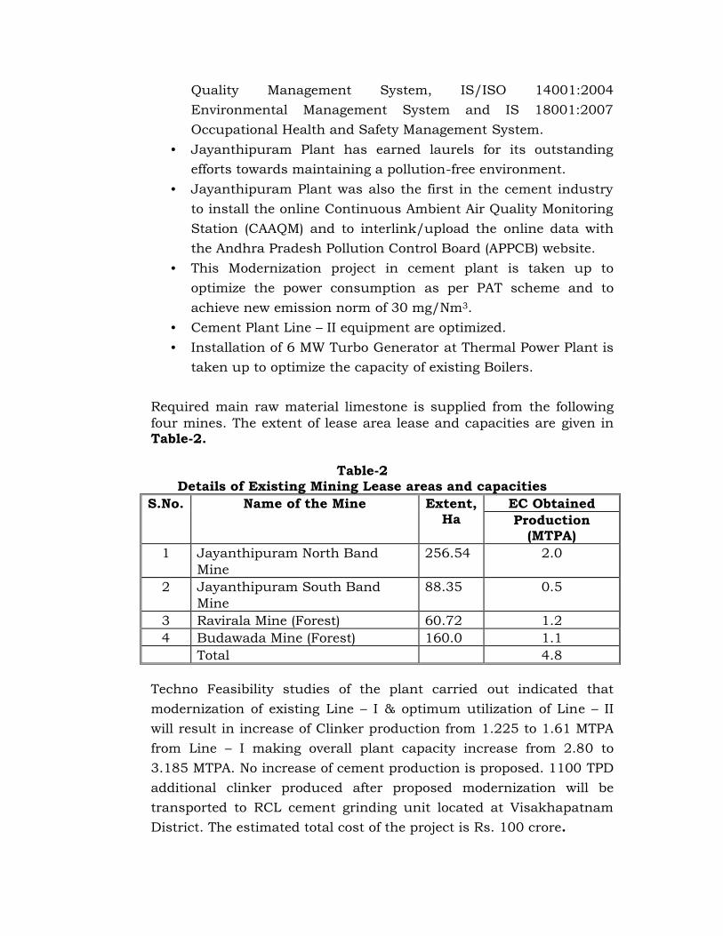
Quality Management System, IS/ISO 14001:2004Environmental Management System and IS 18001:2007Occupational Health and Safety Management System.
• Jayanthipuram Plant has earned laurels for its outstandingefforts towards maintaining a pollution-free environment.
• Jayanthipuram Plant was also the first in the cement industryto install the online Continuous Ambient Air Quality MonitoringStation (CAAQM) and to interlink/upload the online data withthe Andhra Pradesh Pollution Control Board (APPCB) website.
• This Modernization project in cement plant is taken up tooptimize the power consumption as per PAT scheme and toachieve new emission norm of 30 mg/Nm3.
• Cement Plant Line – II equipment are optimized.• Installation of 6 MW Turbo Generator at Thermal Power Plant is
taken up to optimize the capacity of existing Boilers.
Required main raw material limestone is supplied from the followingfour mines. The extent of lease area lease and capacities are given inTable-2.
Table-2Details of Existing Mining Lease areas and capacities
S.No. Name of the Mine Extent,Ha
EC ObtainedProduction
(MTPA)1 Jayanthipuram North Band
Mine256.54 2.0
2 Jayanthipuram South BandMine
88.35 0.5
3 Ravirala Mine (Forest) 60.72 1.24 Budawada Mine (Forest) 160.0 1.1
Total 4.8
Techno Feasibility studies of the plant carried out indicated thatmodernization of existing Line – I & optimum utilization of Line – IIwill result in increase of Clinker production from 1.225 to 1.61 MTPAfrom Line – I making overall plant capacity increase from 2.80 to3.185 MTPA. No increase of cement production is proposed. 1100 TPDadditional clinker produced after proposed modernization will betransported to RCL cement grinding unit located at VisakhapatnamDistrict. The estimated total cost of the project is Rs. 100 crore.

In the year 2009, Ministry of Environment & Forests grantedEnvironmental Clearance for Cement Plant for increase of Clinkerproduction from 2.5 MTPA to 2.80 MTPA & Cement from 2.60 MTPA to3.65 MTPA vide MoEF Letter No. J-11011/403/2006- IA II (I) dated 9th
June, 2009. Copy of MoEF Clearance is enclosed as Annexure-1
ii) Brief Description of Nature of The Project
Cement Plant
Present clinker production of the cement plant with two units is givenbelow:
Kilns Existing(MTPA)Line – I Kiln 1.225Line – II Kiln 1.575Total 2.80
Line-I has present production capacity of Clinker 1.225 MTPA. RCL isnow proposing for production enhancement of Line-I by upgradationand modernization to increase the clinker production capacity from1.225 MTPA to 1.61 MTPA. The salient features of the upgradationand modernization proposal are listed below:
1. The raw meal silo and the kiln feed arrangements including thebins do not undergo major changes, however the bucketelevator feeding to the kiln feed bin needs modification /replacement to cater the upgraded capacity and to feed for boththe lines.
2. The existing Pfister feeder and the solid flow meter are used as itis to feed the existing ILC tower and the new balancing towerrespectively.
3. The existing preheater tower to be de-rated to its originalcapacity of 2500 TPD clinker production and a new twin stringILC balancing tower will be placed in front of the existing towerabove the kiln for 2100 TPD. The combined capacity will be4600 TPD clinker production.
4. The design specifications of both the preheater fans and reusingthe existing preheater fan for the existing tower. The newbalancing tower preheater fan is considered new.

5. The kiln to be speeded up for the target capacity and hence thegirth gear, pinion and the gear box needs to be changedpertaining to kiln.
6. A new high efficiency CB cooler with ABC inlet & MF HRB willreplace the existing cooler and hammer breaker to cater theincrease in capacity and for improved energy efficiency.
7. The cooler vent system shall be reused to cater the increasedcapacity with 200 mg/Nm3 dust emissions. To cater therequirement of 30 mg/Nm3, the possibility of upgrading theexisting ESP is not a viable solution, due to the prevailinginternal conditions of the existing ESP. Hence a new ESP isproposed. However the existing ESP fan will be reused as it is.
8. The layout feasibility of placing the new ESP above the coolerDPC is being explored and found to be possible with thepreliminary assessment. This will bring down the downtimeconsiderably.
9. The bag house reusability is explored.10. A new Duoflex burner to cater the increased capacity and coal
change to be installed. However the same will be validated afterthe present study being conducted by FLS at RCL plants.
11. A new fine coal bin and dosing system with Pfister feeder isproposed for the new balancing ILC tower feeding. The existingkiln firing system and the existing calciner firing system willalso be replaced by Pfister system.
12. It is inevitable to pump coal meal from Line 2 to have smoothoperations of Line 1 and Line 2 at its maximum outputs. Anadditional fine coal bin of 60 MT capacities and the conveyingsystem of 25 TPH capacity to pump fine coal from line2 to line 1is considered.
13. This Modernization project is taken up to optimize the powerconsumption as per PAT scheme and to achieve new emissionnorm of 30 mg/Nm3.
The details of the cement plant capacities after the proposedmodernization is presented in Table-3.
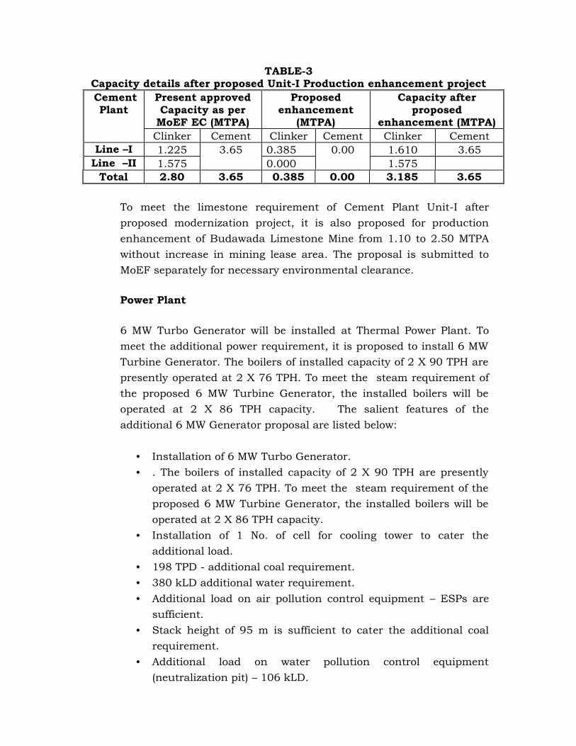
TABLE-3Capacity details after proposed Unit-I Production enhancement projectCementPlant
Present approvedCapacity as per
MoEF EC (MTPA)
Proposedenhancement
(MTPA)
Capacity afterproposed
enhancement (MTPA)Clinker Cement Clinker Cement Clinker Cement
Line –I 1.225 3.65 0.385 0.00 1.610 3.65Line –II 1.575 0.000 1.575
Total 2.80 3.65 0.385 0.00 3.185 3.65
To meet the limestone requirement of Cement Plant Unit-I afterproposed modernization project, it is also proposed for productionenhancement of Budawada Limestone Mine from 1.10 to 2.50 MTPAwithout increase in mining lease area. The proposal is submitted toMoEF separately for necessary environmental clearance.
Power Plant
6 MW Turbo Generator will be installed at Thermal Power Plant. Tomeet the additional power requirement, it is proposed to install 6 MWTurbine Generator. The boilers of installed capacity of 2 X 90 TPH arepresently operated at 2 X 76 TPH. To meet the steam requirement ofthe proposed 6 MW Turbine Generator, the installed boilers will beoperated at 2 X 86 TPH capacity. The salient features of theadditional 6 MW Generator proposal are listed below:
• Installation of 6 MW Turbo Generator.• . The boilers of installed capacity of 2 X 90 TPH are presently
operated at 2 X 76 TPH. To meet the steam requirement of theproposed 6 MW Turbine Generator, the installed boilers will beoperated at 2 X 86 TPH capacity.
• Installation of 1 No. of cell for cooling tower to cater theadditional load.
• 198 TPD - additional coal requirement.• 380 kLD additional water requirement.• Additional load on air pollution control equipment – ESPs are
sufficient.• Stack height of 95 m is sufficient to cater the additional coal
requirement.• Additional load on water pollution control equipment
(neutralization pit) – 106 kLD.

iii) Need for the project and its importance to the country and orregion.
The cement market has growth potential due to the centralgovernment liberalization policies and new schemes for housing, roadprojects. Cement demand growth is anticipated to be about 9 to 10%increase mainly through road projects (Golden Quadrilateral), HousingProjects (1.3 million houses in rural & 0.7 million in urban areas).Continuous demand for exports to China and other South-East Asiancountries along with the increased requirement of the domestic sectorhave led all the cement manufacturers in the country to plan forincreased capacities.
With a view to capture growing opportunity demand, the managementRCL wants to take up the section wise capacity balancing andoptimization of Unit-I. The proposed modernization will enable thecompany to maximize its profitability by optimum utilization oftechnology, manpower, present infrastructure and capital.
The cost of production will substantially reduce due to reduction incost of power, fuel, financial charges and other fixed overheads onaccount of large scale economics due to higher volume of productionand sales.
It would also enable the company to withstand against theconsiderable competitive pressure from large-scale units in thecountry and also to create wider brand loyalty for the product.
The increase of production within the existing plant is based on thefollowing considerations
• Proximity of the site to captive limestone mines and abundantavailability of reserves.
• Market demand• Availability of land – no further land is proposed to be acquired• Availability of existing infrastructure.• RCL is having rail siding within the plant. This rail way line
helps in transporting cement from the cement plant to the
market and obtaining raw materials like coal, gypsum and otheradditives, etc.
iv) Demand – supply Gap
In the recent budget speech the Hon’ble Finance Minister and PrimeMinister have emphasized on development of Infrastructure, housing,Irrigation, etc., all over the country. Per capita consumption of cementin India is only 180 kg against the world average of about 340 kgwhereas per capita consumption in China (a developing nation likeIndia) is 1000 kg.
With highest importance being given by Central and StateGovernments for development of infrastructure in the Country i.e.,National High-ways, State highways, Rural road net work, housingsector, construction of dams, canal net work for irrigation,development of power sector which require huge quantity of cement,demand growth in future is expected to be about 8% to 9% perannum. However, as many units approximately with a capacity of 70-80 Million MT will enter into production during next two years, therewill be a mismatch between supply and demand for some period.Accordingly, the boom enjoyed by the cement industry will be overnow and it may see intense competition for next 2-3 years. However,in the long run, considering expected high level growth on Indianeconomy, the prospects of cement industry are expected to be bright.
Now State and Central Governments are providing thrust forinfrastructure development and housing to the poor people. Also Govt.is giving incentives for construction of own houses by the middle classpeople. Cement is one of the main commodity for construction ofstructures, houses and infrastructures. Thus continued growth ofcement industry is expected for next few decades.
Growth of infrastructure, Irrigation and housing scenarioautomatically drives the increased requirement of Cement in themarket.
v) Imports .Vs. Indigenous Production
Not applicable. This is production enhancement project of existingCement Plant
vi) Export possibility
Not applicable. This is production enhancement project of existingCement Plant to meet the domestic demand.
vii) Domestic / export markets
This is production enhancement project of existing Cement Plant tomeet the domestic markets demand.
viii) Employment generation (direct and indirect) due to theproject.
This is only production enhancement project, hence only indirectemployment may be generated.
3. PROJECT DESCRIPTION
i. Type of project including interlinked and interdependentprojects, if any
The present proposal is for production enhancement of Cement PlantLine-I of RCL. Cement Plant Line-I has present production capacity ofClinker 1.225 MTPA. RCL is now proposing for productionenhancement of Line-I by upgradation and modernization to increasethe clinker production capacity from 1.225 MTPA to 1.61 MTPA.
To meet the additional power requirement, it is proposed to install 6MW Turbine Generator. The boilers of installed capacity of 2 X 90 TPHare presently operated at 2 X 76 TPH. To meet the steam requirementof the proposed 6 MW Turbine Generator, the installed boilers will beoperated at 2 X 86 TPH capacity.
To meet the limestone requirement of Cement Plant Unit-I afterproposed modernization project, it is also proposed for productionenhancement of Budawada Limestone Mine from 1.10 to 2.50 MTPAwithout increase in mining lease area. The proposal is submitted toMoEF separately for necessary environmental clearance.
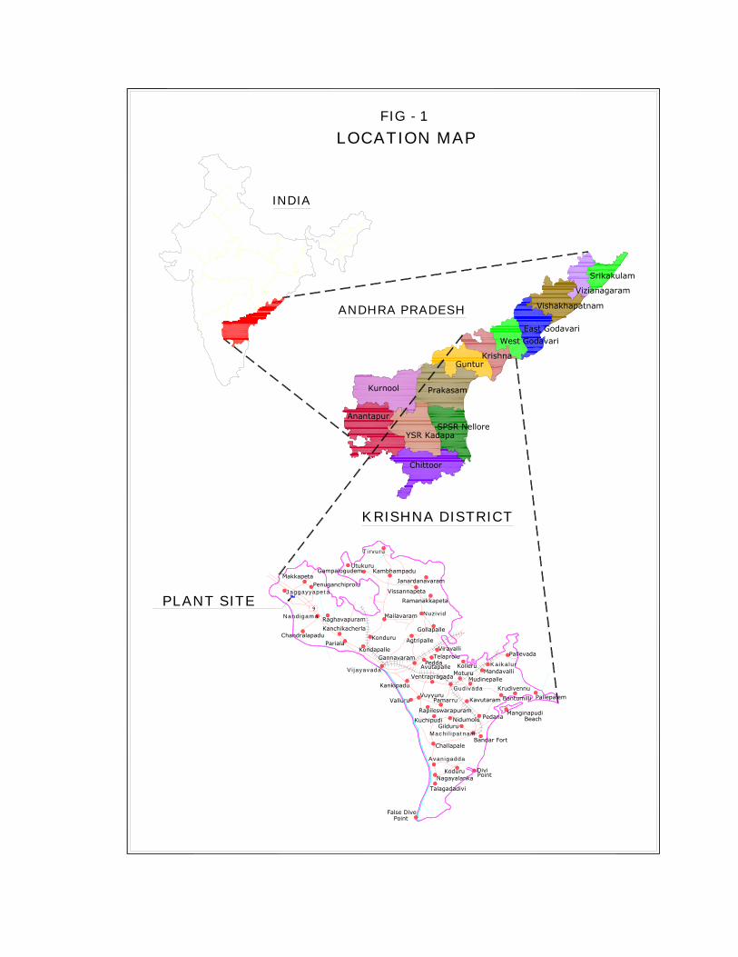
ii. Location (map showing general location, specific location, andproject boundary & project site layout) with co-ordinates.
RCL is located at Jayanthipuram Village, Jaggayapeta Mandal,Krishna District of Andhra Pradesh. The Plant site is a part of theSurvey of India Topo sheet No. 65/D/1. The site falls between A)16°52'24.90"N - 80° 7'8.30"E" B) 16°52'41.20"N - 80° 7'29.40"ENorth latitude and East Longitude with an average altitude of 60mabove MSL.
Break-up of present land use is given in Table-4. The location map ofthe site and layout is shown in Figure-1 and Figure-2 respectively.
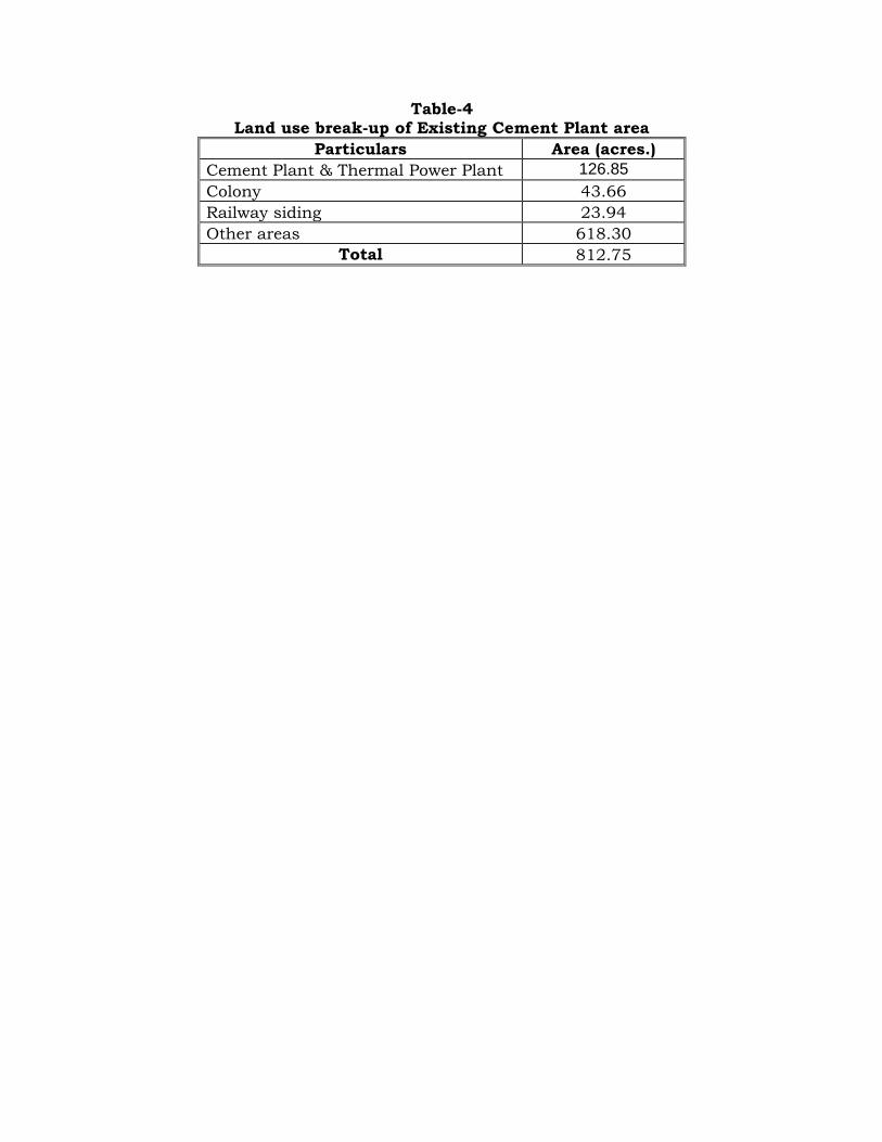
Table-4Land use break-up of Existing Cement Plant area
Particulars Area (acres.)Cement Plant & Thermal Power Plant 126.85Colony 43.66Railway siding 23.94Other areas 618.30
Total 812.75
ANDHRA PRADESH
LOCATION MAP
Chittoor
SPSR Nellore
Prakasam
GunturKrishna
Kurnool
Anantapur
YSR Kadapa
West GodavariEast Godavari
Vishakhapatnam
Vizianagaram
Srikakulam
FIG - 1
INDIA
Nidumolu
Valluru
9
KRISHNA DISTRICT
PLANT SITE
Tirvuru
VentrapragadaMoturuKolleru
Point
Rapileswarapuram
Mailavaram
Bantumilli
Pallevada
AvutapallePedda
TelaproluViravalli
Gilduru
Divi
Mudinepalle
Talagadadivi
NagayalankaKoduru
Challapale
Pamarru
Bandar Fort
BeachManginapudi
PallepalemKrudivennu
Mandavalli
Kavutaram
PedanaKuchipudi
Vuyyuru
Kankipadu
Gannavaram
GampalogudemUtukuru
Kambhampadu
ParialaKonduru Agtripalle
Gollapalle
RamanakkapetaVissannapeta
Janardanavaram
Kondapalle
KanchikacherlaRaghavapuram
Chandralapadu
PenuganchiproluMakkapeta
Kaikalur
Nuzivid
Vijayavada
Nandigama
Gudivada
Machilipatnam
Avanigadda
False DivePoint
Jaggayyapeta

Figure-2
231513
S TK1
2
S 30
1
S 35
S 31
3
4
S 19
S 21
5
6
S 15 S 20
22S 17
S TK4
29S 35
S 23
7
S 25
9
8
12
11
S 24
43
42 42
S TK628
46
S 22
14
16 17
16
1819
21
20
S 18
44
49S TK 11
S 33 45
47
2634
30
31
34
32
35
50
5148
S 13
40
38
41
39
T2 WATER TREATMENT PLANT
T23 CRUSHER & SCREEN HOUSE
T28 HP & LP DOSING SKIDS
T25 D .M TANK
T30 CHP MCC ROOM
T27 CBD & IBD TANKS
T26 COMPRESSORS HOUSE &
T3 RAW&FIRE WATER PUMP HOUSE
T12 AUXILLARY TRANSFORMERS
T6 AUXILLARY COOLING WATER PUMPS
T21 P.A FANST22 TRANSFER TOWER
T19 F.D . FANST18 LDO SERVICE TANKT17 BED ASH SILO
T20 BOILERS 2 Nos
T16 FLY ASH SILOST15 I.D FANS
T11 BFP AREA
T9 STG UNLOADING BAY
T4 COOLING TOWER
T7 SIDE STREAM FILTERST8 TURBINES HALL
T10 DEAERATOR
T5 COOLING WATER PUMPS
T1 RAW WATER RESERVOIR
G.K.Ramesh 141018
S 18
S4
S 12 S 11
S9
S 10
69
S5S1
S7
S8S6
S2
S 34
P7
P2
P2
P6
P8
P 18
P 17P 11
P 31P 14
P 10
P 12
P STK1
P STK2
P STK3
P 22P 23
P5
P9
5
P 19
P 21
P4
P3
T14 CHIMNEY
T24 DAY STORAGE BIN
T29 PLANT AIR RECEIVERS
T31 AIR WASHER UNITT32 ASH HANDLING AIR RECEIVERS
S3
P 26
10
52
53
55
55
54
55
55
P 24 P 24
P 24
P 20
2 S ECONDA RY SCREEN
19 COAL BAG HOUSE
29 ALTERNATE FUEL SHED30 DPC TO CEMENT MILL
31 CEMENT MILL HOPPERS
25 CLINKER SILO NO.2
27 COAL & GYPSUM YARD28 COAL CRUSHER BUILDING
26 UNBURNT CLINKER SILO
22 COOLER ESP
20 CENTRAL CONTROL ROOM21 GRATE COOLER
24 CLINKER SILO NO.123 DPC FROM COOLER TO SILO
15 KILN FEED BELT BUCKET ELEV.
12 RAW MILL BELT BUCKET ELEV.
16 KILN17 HOT ESP18 COAL MILL
14 PREHEATER13 C .F. SILO
9 RAW MILL CYCLONES10 RAW MILL RECIRCULATION SYS.
4 CBA SYSTEM5 L.S PREBLENDING YARD
7 RAW MATERIAL HOPPERS
3 CBA HOPPERS
6 ADDITTIVE STORAGE SHED
8 RAW MILL
1 LIME S TONE CRUSHER
48 PADDLE MIXER49 COM P RE S S OR HOUS E FOR SLAG MILL
45 BAG HOUSE FOR SLAG MILL
39 WAGON TIPPLER MCC&PUMP HOUSE
57 OIL TANKS
47 SILO FOR GROUND SLAG46 SILO FOR GROUND CLINKER
44 SLAG MILL43 FEED HOPPERS FOR SLAG MILL42 SLAG STORAGE YARD41 TRUCK TIPPLER40 WAGON UNLOADING HOPPERS
38 WAGON TIPPLER
51 CEMENT SILOS No. 1,2,3&452 PACKING PLANT53 TRUCK LOADING BUILDING54 WAGON LOADING CONVEYORS55 WAGON LOADING PLATFORMS56 POWER PLANT BUILDING
32 CEMENT MILL BUILDING
LINE-I MAIN BUILDINGS SERVICE BUILDINGS
S5 FIRE FIGHTING EQUIP.SHED
S9 WEIGH BRIDGE FOR TRAILERSS8 WEIGH BRIDGE & CDS OFFICE
S16 CEMENT MILL SUB-STATION
S12 132KV MAIN SUB-STATION
S18 CAR & SCOOTER PARKINGS17 COOLER ESP FAN SPRS ROOM
S2 SECURITY OFFICE
S20 OVER HEAD WATER TANK
S11 SWITCH YARD.
S15 WORK SHOPS14 STORESS13 GUNNY BAG GODOWN
S19 PUMP HOUSE
S4 CYCLE STAND
S7 ADMIN ISTRATIVE OFFICES6 CDS COMPUTER ROOM
S3 CANTEEN
S10 APSEB SWITCH YARD
S1 TIME OFFICE
S23 D IN ING HALL AT RAW MILL
S21 GROUND LEVEL WATER TANK
S26 MINES DEPT. FIELD OFFICE
S24 RAW MILL MCC ROOMS25 KILN FEED MCC ROOM
S22 RAW MILL SUB-STATION
S27 AUTO GARAGE
S 34 IN- M OTION W A GON WEIGHING SYS.
S29 HSD CONSUMER PUMP STATIONS28 DUMPERS MAINT. SHED
S32 D IN ING HALL AT PACKING PLANTS31 D IN ING HALL AT CRUSHER DEPT.
S33 SLAG MILL SUB-STAION & MCC
S35 TOILET BLOCK
S30 CRUSHER SUB-STATION
POWER PLANT BUILDINGS
P 32
P 33
S 32
S 35
P1
S TK2
S TK3
S TK 12
58 UNDER GROUND CABLE TUNNEL
T13 ESPs 2 Nos
65
P 34
ESP CONTROL ROOM
P 16 P 30
66
59 OVER HEAD CABLE GALLERY
P 25
P 20 M ODIFICA TION FOR CEMENT MILL
P 4 A DDITIV ES S TORA GE YARD
P 18 CLINKE R EX PORT SYSTEM.
P 13 COAL S TORA GE Y ARD 2P 12 COAL CRUSHER
P 17 CLINKE R SILO No. 3 & HANDLING SY S.
P 14 LINE -II HOT ES P.
P 6 L INE- II RAW M ILLP 7 L INE- II RAW M ILL BA G HOUS E &
P 10 LINE -II KILN
P 5 L INE- II RAW M ATERIA L HOPPERS
P 8 K ILN FE ED S YSTEMP 9 L INE- II P RE HEATER
P 11 LINE -II COOLER & COOLE R E.S.P
P 2 L INE- II L .S S TORA GE Y ARD
2nd LINE BUILDINGS
P 1 B A G FILTE R FOR L.S CRUSHER
P 3 A DDITIV ES CRUSHER
RA W MILL S UB STATION
P 19 CLINKE R PREGRINDING VRPM
Pos Descr iption
P 15
P15 LINE-II COAL MILL&COAL MILL BAG FILTERP 16 INERT GA S GE NE RA TOR HOUSE
P 27
P 28
P 29
A ND TRUCK & WAGON LOA DING P LA NT
P 21 BULK LOA DING SYSTEM
P 24 EX TE NS ION OF P ACKING P LANT,P 23 NE W FLY AS H SILOP 22 NE W CE ME NT S ILO
P 25 RA IN P ROTE CTION SHED A T PP
Pos Descr iption
P 27 LINE -1 RM BA G HOUS E DUCTINGP 26 VRPM S UB S TA TION B UILDING
P 29 CE ME NT S ILO FE EDING SYSTEMP 28 LINE -1 RAW M ILL BA G HOUSE
P 31 LINE -II COOLER M CC ROOMP 30 DINING HALL AT LINE- II COOLE R AREA
P33 MCC ROOM FOR ADDITIVE HANDLING SYS.P32 MCC ROOM FOR CLINKER EXPORT SYS.
P 34 ELECTRICAL WORK SHOP
P 11
S1
25
24
P 35 TOILE T AT WORK SHOPP36 TOILET BLOCK AT LINE-II COOLER AREAP37 TOILET BLOCK AT CEMENT MILLS AREA
P 36
P 38
P 37
P 35
P 38 DINING HALL AT CEM ENT MILLS AREA
PRO PO SED
F
F
Min es O ffice
P 41
P 40
P 39 OP EN S TORA GE Y ARD FOR COALP 40 SURGE BIN FOR CLINKE R DROP TESTP4 1 T RUCK L O ADING SYS. FOR EXPORT CLINKER
11 BARE SUPP. STR. OF REMOVED R.M ESP
33
34 CEMENT MILL RECIRCULATION ELEVATOR35 CLOSE CIRCUIT SYSTEM FOR C.MILL
33 300T FLY ASH FEED BIN FOR C.M
37
37 C.M ESP SUPP. STR CONVERTED AS STORE ROOM FOR VRPM SECTION
36
50 FLY ASH SILO No.1
36 B A G HOUS E FOR CLOSE CIRC. SYSTEM
2nd/EIA-002K
P 13
60 BELT CONV FROM L1 COAL HOPPER DISCHARGE TO L-2 HOPPER BOTTOM61 BELT CONV FOR FEEDING GYPSUM
FROM SLAG YARD TO CEMENT MILL
60
S CHOOL
Existing Greenbelt Area
Proposed Greenbelt Area
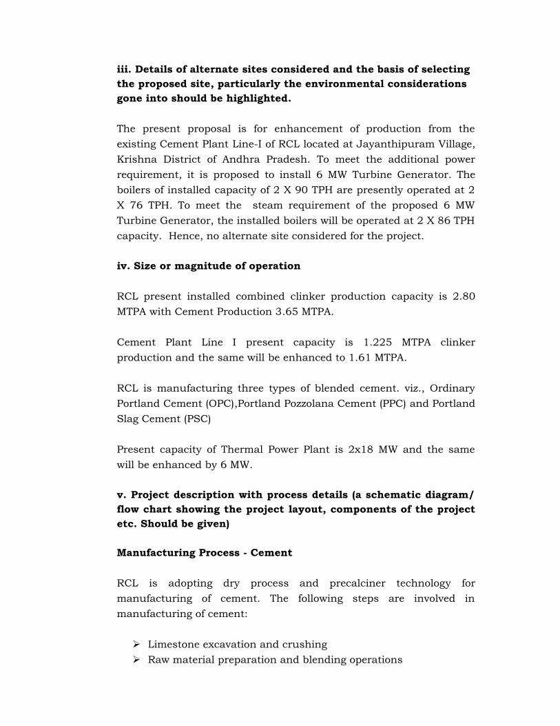
iii. Details of alternate sites considered and the basis of selectingthe proposed site, particularly the environmental considerationsgone into should be highlighted.
The present proposal is for enhancement of production from theexisting Cement Plant Line-I of RCL located at Jayanthipuram Village,Krishna District of Andhra Pradesh. To meet the additional powerrequirement, it is proposed to install 6 MW Turbine Generator. Theboilers of installed capacity of 2 X 90 TPH are presently operated at 2X 76 TPH. To meet the steam requirement of the proposed 6 MWTurbine Generator, the installed boilers will be operated at 2 X 86 TPHcapacity. Hence, no alternate site considered for the project.
iv. Size or magnitude of operation
RCL present installed combined clinker production capacity is 2.80MTPA with Cement Production 3.65 MTPA.
Cement Plant Line I present capacity is 1.225 MTPA clinkerproduction and the same will be enhanced to 1.61 MTPA.
RCL is manufacturing three types of blended cement. viz., OrdinaryPortland Cement (OPC),Portland Pozzolana Cement (PPC) and PortlandSlag Cement (PSC)
Present capacity of Thermal Power Plant is 2x18 MW and the samewill be enhanced by 6 MW.
v. Project description with process details (a schematic diagram/flow chart showing the project layout, components of the projectetc. Should be given)
Manufacturing Process - Cement
RCL is adopting dry process and precalciner technology formanufacturing of cement. The following steps are involved inmanufacturing of cement:
Limestone excavation and crushing Raw material preparation and blending operations
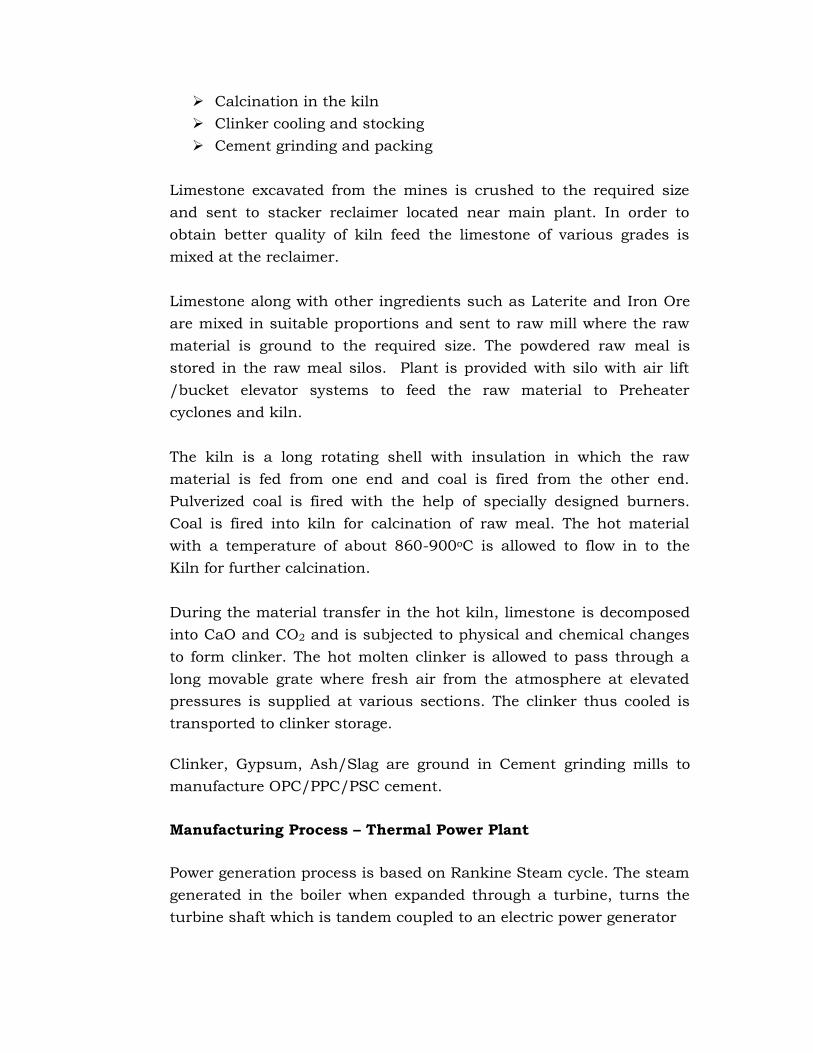
Calcination in the kiln Clinker cooling and stocking Cement grinding and packing
Limestone excavated from the mines is crushed to the required sizeand sent to stacker reclaimer located near main plant. In order toobtain better quality of kiln feed the limestone of various grades ismixed at the reclaimer.
Limestone along with other ingredients such as Laterite and Iron Oreare mixed in suitable proportions and sent to raw mill where the rawmaterial is ground to the required size. The powdered raw meal isstored in the raw meal silos. Plant is provided with silo with air lift/bucket elevator systems to feed the raw material to Preheatercyclones and kiln.
The kiln is a long rotating shell with insulation in which the rawmaterial is fed from one end and coal is fired from the other end.Pulverized coal is fired with the help of specially designed burners.Coal is fired into kiln for calcination of raw meal. The hot materialwith a temperature of about 860-900oC is allowed to flow in to theKiln for further calcination.
During the material transfer in the hot kiln, limestone is decomposedinto CaO and CO2 and is subjected to physical and chemical changesto form clinker. The hot molten clinker is allowed to pass through along movable grate where fresh air from the atmosphere at elevatedpressures is supplied at various sections. The clinker thus cooled istransported to clinker storage.
Clinker, Gypsum, Ash/Slag are ground in Cement grinding mills tomanufacture OPC/PPC/PSC cement.
Manufacturing Process – Thermal Power Plant
Power generation process is based on Rankine Steam cycle. The steamgenerated in the boiler when expanded through a turbine, turns theturbine shaft which is tandem coupled to an electric power generator

vi. Raw material required along with estimated quantity, likelysource, marketing area of final products, mode of transport of rawmaterial and finished product.
The raw material required for production of clinker is Limestone, IronOre, Laterite and Coal. The requirement of raw material per annum onan average for the production clinker at full capacity of 3.185 MTPA ispresented in Table -6.
Table-6Raw Material Requirement
S.No. Raw Material Existing 2.80 MTPAClinker & 3.65 MTPA
Cement, millionTonne per Annum
Proposed 3.185MTPA Clinker &
3.65 MTPACement, million
Tonne per Annum1 Limestone 3.91 4.452 Iron Ore 0.097 0.113 Laterite 0.159 0.1814 Coal 0.432 0.490
Total ClinkerProduction
2.80 3.185
Clinker export forother Units
0.835 1.185
5 Clinker usedfor CementManufacturing
1.964 1.964
6 Gypsum 0.286 0.2867 Fly Ash 1.112 1.1128 Slag 0.286 0.286
Total CementProduction
3.65 3.65
Coal is the raw material for Thermal Power Plant. The coalrequirement per annum on an average for the production 42 MW is:
For existing 2 x 18MW Plants
For proposed 6MW Generator
Total 42 MWPowerGeneration
Coal 1188 198 1386
For obtaining raw materials like coal, gypsum, additives and fortransporting cement from the cement plant to the market, well
connected roads are available. The National Highway (NH-9)connecting Vijayawada – Hyderabad, at a distance of about 2.4 km inNE Direction. Blacktop double road is available from Chillakallu toPlant site. Nearest railway siding is Jaggaiahpet 1.5 km away fromexisting site.
RCL has provided railway siding within the Cement plant. ThisJaggaiahpet railway line is connecting to Kazipet- Vijayawada mainline at Motumarri.
vii. Resource optimization / recycling and reuse envisaged in theproject, if any, should be briefly outlined.
Jayanthipuram North Band Mine, Jayanthipuram South Band Mine,Ravirala Mine (Forest) and Budawada Mine (Forest) are cateringlimestone to Cement Plant
Limestone from Budawada Limestone Mine is of high grade. Thereforethis limestone is blended with low grade produced from other minesand supplied to Cement plant for optimum utilization of resources.
Cooling water circuit is close circuited, thereby ensuring no generationof wastewater;
The process, selected envisages re-cycling all the material collected inthe pollution control equipment whereby ensuring no generation ofsolid waste.
It is also proposed to utilize high calorific value hazardous waste(organic liquid hazardous waste) as alternative fuel in kiln system.RCL has obtained hazardous waste authorization from APPCB.
viii. Availability of water its source, energy / power requirement
Water
Water is not required for the cement manufacturing process. Water isrequired for cooling, dust suppression, sanitary facilities andgardening. The present water requirement for RCL Cement Plantscomplex is 6259.8 m3/day. Additional water requirement for cement

plant modernization is 50 m3/day. The additional water requirementfor 6 MW Generator is 380 m3/day. The source of water is bore wells.RCL has obtained necessary permission from Ground WaterDepartment for water drawl at the rate of 7000 m3/day.
Power
The peak power consumption in the RCL Cement plant complexincluding mine is 45 MW. Power requirement is met from existing2x18 MW captive thermal power plant and proposed 6 MW Generator.Additional power requirement is from grid.
xi. Quantity of waste to be generated (liquid and solid) andscheme for their management / disposal.
In cement plant water is used for cooling and raw material addition atvarious stages. This water is totally absorbed in the process or will besubjected to evaporation and hence no wastewater is released fromthe cement plant.
Wastewater generated is only from domestic activities at cement plantand residential colony. A full fledge sewage treatment plant (STP) is inoperation designed for a maximum load of 650 m3/day. Treateddomestic wastewater is reused for greenbelt development within RCLcement plant complex.
Additional waste water generation from 6 MW Generator system is 106m3/day. This will be neutralized in the existing neutralization pit ofsize 4m x 3m x 2m. Neutralized wastewater is reused for greenbeltdevelopment and as process water in cement plant within RCL cementplant complex.
No solid waste is generated from the cement plant. The dust collectedin the pollution control devices is being 100% recycled back to theprocess.

x. Schematic representations of the feasibility drawing which giveinformation of EIA purpose.
The location map of the site and layout is shown in Figure-1 andFigure-2 respectively.
4. SITE ANALYSIS
i. Connectivity
Nearest railway line connecting Madhira - Mellacheruvu of SouthCentral Railway line, at a distance of 1.5 km to North direction fromthe Plant site. Dedicated railway line to the cement plant is beingoperated from Jaggayyapet railway station for transportation of rawmaterials & products.
The nearest railway station is Motimarri at 23.0 km in ENE directionand Major Railway station is Vijayawada – 70.0 km in SE direction.
For transporting cement from the cement plant to the market andobtaining raw materials like coal, gypsum and other additives, wellconnected roads are available. The National Highway (NH-9)connecting Vijayawada – Hyderabad, at a distance of about 2.4 km inNE.
ii. Land form, land use and land ownership.
Cement plant is located in an area of 812.75 acre which is totallyowned by RCL. No additional land is required for this modernizationas the proposed modernization is in terms of upgradation andmodernization of existing process equipment of existing Line-I andoptimum utilization of Line - II. Break-up of present land use ofexisting RCL cement plant complex is given in Table-4 and RCLcement plant complex layout is shown in Figure-2. No additional landwill be required for proposed modernization project.
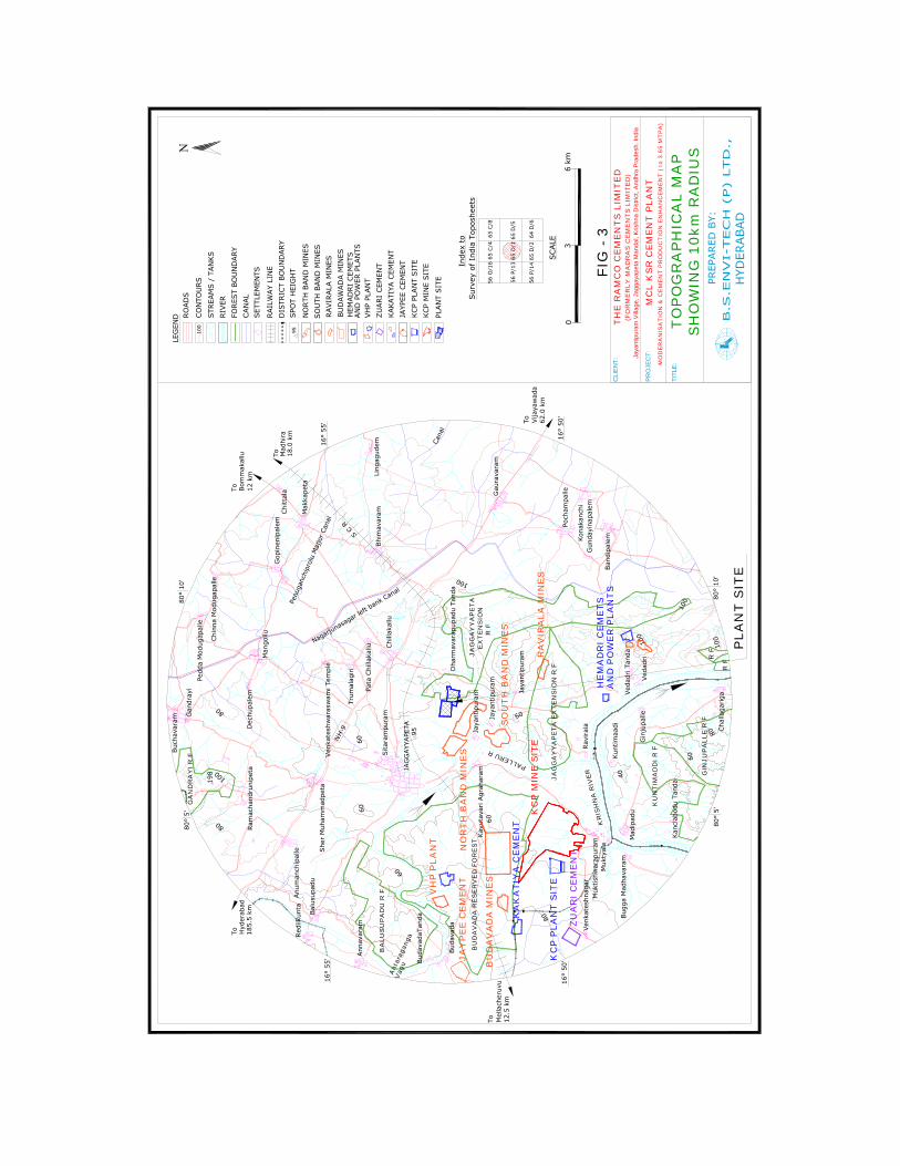
iii. Topography (along with map)
The existing RCL Cement plant complex site is located at an elevationof 62 m above MSL. The area falls in the eastern fringe of the Deccanplateau bordering the northern portion of Eastern Ghats (South). Thetopography of the area is gently undulating flat area. The surroundingarea is traversed by various nallahs that form a sub-dentritic andparallel drainage pattern. Most of the streams are dry during the non-monsoon period fed by the excess irrigation water from the commandarea of Nagarjunsagar Left Bank Canal. The Krishna river flows in the

southern direction with the closest point about 5.4 km south of thesite. The topographical map of the site is shown in Figure-3.
iv. Existing land use pattern (agriculture, non-agriculture, forest,water bodies (including area under CRZ), shortest distances fromthe periphery of the project to periphery of the forests, nationalpark, wild life sanctuary, eco sensitive areas, water bodies(distance from the HFL of the river), CRZ, in case of notifiedindustrial area, a copy of the Gazette notification should begiven.
Break-up of present land use of existing RCL cement plant complex isgiven in Table-4. No additional land will be required for proposedmodernization project.
• There are no national parks or wildlife sanctuary within 10 kmof the subject mine area.
• No ecologically sensitive areas within 10 km of the plant area.• There are no sensitive places of notified archaeological,
historical or tourist importance within 10 km from the plantarea
v. Existing Infrastructure
For transporting cement from the cement plant to the market andobtaining raw materials like coal, gypsum and other additives, wellconnected railway siding and road are available.
RCL has provided a full-fledged colony with necessary infrastructure
Ant
arag
anga
Vag
u
100
NH
-9
KC
P P
LAN
T S
ITE
PLA
NT
SIT
E
16°
50'
Vija
yaw
ada
62.0
km
To
80°
5'80
° 10
'
Hyd
erab
adTo 18
5.5
km
16°
55'
Bom
mak
allu
To 12 k
m
Mad
hira
To 18.0
km
Mel
lach
eruv
uTo 12
.5 k
m
16°
50'
16°
55'
80°
10'
80°
5'
Bud
avad
a
Bud
avad
aTan
da
Ven
kate
shna
gar
Muk
tishw
arap
uram
Bug
ga M
adha
vara
mM
adip
adu
Cha
llaga
riga
Ved
adri
Ved
adri
Tan
da
Rav
iral
a
Gin
jupa
lle
Kan
clab
odu
Tand
a
Kun
timaa
di
Muk
tyal
a
JAG
GAYY
APE
TA
Sita
ram
pura
m
Kav
utav
ari A
grah
aram
Jaya
ntip
uram
Jaya
ntip
uram
Dha
rmav
arap
upad
u Ta
nda
Jaya
ntip
uram
She
r M
uham
mad
peta
Trum
alag
iri
Anu
man
chip
alle
Ann
avar
am
Red
iikun
ta
Bal
usup
adu
Pata
Chi
llaka
llu Chi
llaka
llu
Ling
agud
em
Gan
dray
i
Buc
hava
ram
Bhi
mav
aramM
akka
peta
Chi
ttal
aG
opin
enip
alem
Man
gollu
Dec
hupa
lem
Ram
acha
ndru
nipe
ta
Ban
dipa
lem
Poch
ampa
lle
Kon
akan
chi
Gun
dayi
napa
lem
Gau
rava
ram
Chi
nna
Mod
ugap
alle
Pedd
a M
odug
apal
le
Ven
kate
shw
aras
wam
i Tem
ple
S C R
PALLERU R
KR
ISH
NA
RIV
ER
80
80
100
60
60
60
60
40
100
6060
Cana
l
Nagarjunasa
gar left
bank Canal
JAG
GA
YY
AP
ET
A E
XT
EN
SIO
N R
F
Penu
ganc
hipr
olu
Maj
jor
Cana
l
SH
OW
ING
10k
m R
AD
IUS
TO
PO
GR
AP
HIC
AL
MA
P
CLI
EN
T:
TITL
E:
Jaya
ntip
uram
Vill
age,
Jag
gaya
peta
Man
dal,
Kris
hna
Dis
trict
, And
hra
Pra
desh
. Ind
ia(F
OR
ME
RLY
MA
DR
AS
CE
ME
NT
S L
IMIT
ED
)
PR
OJE
CT:
MO
DE
RA
NIS
AT
ION
& C
EM
EN
T P
RO
DU
CT
ION
EN
HA
NC
EM
EN
T (
to
3.65
MT
PA
)
FIG
- 3
MC
L K
SR
CE
ME
NT
PLA
NT
198
8080
100
100
95
100
95
JAY
PE
E C
EM
EN
T
KC
P M
INE
SIT
E
VH
P P
LAN
T
RA
VIR
ALA
MIN
ES
SO
UT
H B
AN
D M
INE
S
NO
RT
H B
AN
D M
INE
S
KA
KA
TIY
A C
EM
EN
T
HE
MA
DR
I C
EM
ET
SA
ND
PO
WE
R P
LAN
TS
R F
KU
NT
IMA
DD
I R
F
JAG
GA
YY
AP
ET
AE
XT
EN
SIO
N
BA
LUS
UP
AD
U R
F
R F
R F
GIN
JUP
ALL
E R
F
GA
ND
RA
YI
R F
BU
DA
VA
DA
RE
SE
RV
ED
FO
RE
ST
ZU
AR
I C
EM
EN
T
56 P
/14
65 D
/2 64
D/6
56 O
/16
65 C
/4 65
C/8
56 P
/13
65 D
/1 6
5 D
/5
Sur
vey
of I
ndia
Top
oshe
ets
Inde
x to
SCALE
03
6 km
RO
AD
S
CO
NTO
URS
RIV
ERSTR
EAM
S /
TAN
KS
FORES
T BO
UN
DARY
SET
TLEM
ENTS
DIS
TRIC
T BO
UN
DARY
SPO
T H
EIG
HT
LEG
END C
AN
AL
RAIL
WAY
LIN
E
KCP
PLAN
T SIT
EJA
YPEE
CEM
ENT
KAKATI
YA C
EMEN
TZU
ARI
CEM
ENT
VH
P PL
AN
T
NO
RTH
BAN
D M
INES
KCP
MIN
E SIT
E
PLAN
T SIT
E
HEM
AD
RI
CEM
ETS
AN
D P
OW
ER P
LAN
TS
SO
UTH
BAN
D M
INES
BU
DAW
AD
A M
INES
RAVIR
ALA
MIN
ES
TH
E R
AM
CO
CE
ME
NT
S L
IMIT
ED
BU
DA
VA
DA
MIN
ES

Cement plant is having a dedicated power supply from captive powerplant to meet the requirement of cement plant, colony and mines
vi. Soil Classification
The most dominant type of soil in the area is the Black-cotton soilwhich is present in thickness ranging from less than a 1 m to asmuch as 1.5 m in the cultivated and agriculture lands. Thinnerpatches of soil are present in the open scrub covered wastelandswhere either sheet rock or stony out crops are absent.
vii. Climate data from secondary sources
The climate of the study region is semi-arid and is characterized bygeneral dryness except during the South West monsoon season. Thearea experiences extreme climate during summer and winter seasons.
As per the records of Indian Meteorological Department, minimumand maximum temperatures recorded in the region in the past 10years were 13.0oC and 47.6oC respectively with an annual rainfall of998 mm. Mean wind speeds observed in the area range between 1-15kmph with predominant winds from E, SE, S and SW during summerand E, SE & S in winter season.
It can be observed from the solar radiation chart that’s published byIMD, the average relative humidity was found to vary between 45 to82%.
viii. Social infrastructure available
A well-equipped Occupational Health center is provided at colony,which has full time Occupational Health Specialist assisted, bycompounders and nurses. Necessary free medicines and medical aid isavailable for the company employees.
A good canteen is provided for the benefit of the employees. Thecanteen serves tea & snacks at subsidized rates to the employees.
Adequate number of shelters with fans, drinking water etc. for takingfood and rest are provided for the benefit of the employees.

Safe hygienic drinking water is provided at the mines. Drinking waterfacility is available near rest shelters.
A full-fledged Training hall is available in the RCL cement plantcomplex. The training to workmen is provided on basics as well as forrefreshers.
The employees are provided with well-designed houses havingelectricity and water connections.
For the education facility of employee’s Children School is provided atcolony.
RCL has spent an amount of Rs 4.0 crores for providing various socialinfrastructure/measures towards Health Care, Education, DrinkingWater / Sanitation / Infrastructure Religious Sports / Cultural /Social / Plantation Water Supply For Agriculture Fields And FloodRelief Activities for the past 11 years.

5. PLANNING BRIEF
i. Planning concept (type of industries, facilities, transportationetc) town and country planning / development authorityclassification.
This is modernization project of existing cement plant Line-I located inthe present cement plant complex. No additional land or civilstructures will be required for proposed modernization project.
ii. Population projection
This is modernization project of existing cement plant Line-I located inthe present cement plant complex.
iii. Land use planning (breakup along with greenbelt etc)
This is modernization project of existing cement plant Line-I locatedwithin the existing RCL cement plant complex. The present land usepattern of the existing RCL cement plant complex is given in Table-4.No additional land will be required for proposed modernization project
iv. Assessment of infrastructure demand (physical & social)
Not applicable.
This is modernization project of existing cement plant Line-I &installation of 6 MW Generator within the existing RCL cement plantcomplex. No physical & social infrastructure is envisaged for theproposed project.
v. Amenities / Facilities
Not applicable.
Existing amenities and facilities are sufficient for proposed project.

6. PROPOSED INFRASTRUCTURE
i. Industrial area (processing area)
No additional infrastructure is proposed for the proposed productionenhancement. It is proposed to increase the clinker productioncapacity from 1.225 to 1.61 MTPA by up-gradation andmodernization.
Major modifications envisaged for cement plant productionenhancement are given below
1. The raw meal silo and the kiln feed arrangements including thebins do not undergo major changes, however the bucketelevator feeding to the kiln feed bin needs modification /replacement to cater the upgraded capacity and to feed for boththe lines.
2. The existing Pfister feeder and the solid flow meter are used as itis to feed the existing ILC tower and the new balancing towerrespectively.
3. The existing preheater tower to be de-rated to its originalcapacity of 2500 TPD clinker production and a new twin stringILC balancing tower will be placed in front of the existing towerabove the kiln for 2100 TPD. The combined capacity will be4600 TPD clinker production.
4. The design specifications of both the preheater fans and reusingthe existing preheater fan for the existing tower. The newbalancing tower preheater fan is considered new.
5. The kiln to be speeded up for the target capacity and hence thegirth gear, pinion and the gear box needs to be changedpertaining to kiln.
6. A new high efficiency CB cooler with ABC inlet & MF HRB willreplace the existing cooler and hammer breaker to cater theincrease in capacity and for improved energy efficiency.
7. The cooler vent system shall be reused to cater the increasedcapacity with 200 mg/Nm3 dust emissions. To cater therequirement of 30 mg/Nm3, the possibility of upgrading theexisting ESP is not a viable solution, due to the prevailinginternal conditions of the existing ESP. Hence a new ESP isproposed. However the existing ESP fan will be reused as it is.

8. The layout feasibility of placing the new ESP above the coolerDPC is being explored and found to be possible with thepreliminary assessment. This will bring down the downtimeconsiderably.
9. The bag house reusability is explored. The cyclone water sprayand with the required bleed air conditions to reuse the existingbag house for the upgraded volume.
10. A new Duoflex burner to cater the increased capacity and coalchange to be installed. However the same will be validated afterthe present study being conducted by FLS at RCL plants.
11. A new fine coal bin and dosing system with Pfister feeder isproposed for the new balancing ILC tower feeding. The existingkiln firing system and the existing calciner firing system willalso be replaced by Pfister system.
12. It is inevitable to pump coal meal from Line 2 to have smoothoperations of Line 1 and Line 2 at its maximum outputs. Anadditional fine coal bin of 60 MT capacity and the conveyingsystem of 25 TPH capacity to pump fine coal from line2 to line 1is considered.
The salient features of the additional 6 MW Generator proposal arelisted below:
• Installation of 6 MW Turbo Generator.• To meet the additional power requirement, it is proposed to
install 6 MW Turbine Generator. The boilers of installed capacityof 2 X 90 TPH are presently operated at 2 X 76 TPH. To meet thesteam requirement of the proposed 6 MW Turbine Generator,the installed boilers will be operated at 2 X 86 TPH capacity.
• Installation of 1 No. of cell for cooling tower to cater theadditional load.
• 198 TPD - additional coal requirement.• 380 kLD additional water requirement.• Additional load on air pollution control equipment – ESPs are
sufficient.• Stack height of 95 m is sufficient to cater the additional coal
requirement.• Additional load on water pollution control equipment
(neutralization pit) – 106 kLD.

ii. Residential area (non-processing area)
No additional infrastructure is proposed for production enhancement.Existing amenities and facilities are sufficient.
iii. Greenbelt
RCL has developed greenbelt in an area of 128 ha in and around theRCL cement plant complex.
iv. Social infrastructure
This is modernization project of existing cement plant Line-I locatedwithin the existing RCL cement plant complex. Existing socialinfrastructure will be serving the plant operations.
v. Connectivity (traffic and transportation road/rail/metro/waterways etc.)
Nearest railway line connecting Madhira - Mellacheruvu of SouthCentral Railway line, at a distance of 1.5 km to North direction fromthe Plant site. Dedicated railway line to the cement plant is beingoperated from Jaggayyapet railway station for transportation of rawmaterials & products.
The nearest railway station is Motimarri at 23.0 km in ENE direction.and Major Railway station is Vijayawada – 70.0 km in SE direction.
For transporting cement from the cement plant to the market andobtaining raw materials like coal, gypsum and other additives, wellconnected roads are available. The National Highway (NH-9)connecting Vijayawada – Hyderabad, at a distance of about 2.4 km inNE.
vi. Drinking water management (source & supply of water)
The existing cement plant is having safe drinking water facility.
vii. Sewerage System
This is modernization project of existing cement plant Line-I locatedwithin the existing RCL cement plant complex. Sewerage system isexisting which is connected to sewage treatment plant designed for650 m3/day which is sufficient.
viii. Industrial waste management
Cement Plant - This is existing cement plant. No additional industrialwaste generation is envisaged from proposed modernization project incement plant as the process is dry process.
Thermal Power Plant – Waste water generation will get increased by106 kLD. This will be treated in existing neutralization pit of size 4m x3m x 2m.
ix. Solid waste Management
Cement Plant - No solid waste is generated from the cement plant. Thedust collected in the pollution control devices is being 100% recycledback to the process.
x. Power requirement & Supply /Source.
The peak power consumption in the RCL Cement plant complexincluding mine is 45 MW. This requirement is met from existing 2x18MW Captive Power Plant and proposed 6 MW Generator. Additionalpower requirement is from grid.

7. REHABILITATION AND RESETTLEMENT (R&R) PLAN
i. Policy to be adopted (central / state) in respect of the projectaffected persons including home oustees, land oustees andlandless labourers (a brief out line to be given).
The proposal is for production enhancement of existing Cement PlantLine-I & installation of 6 MW Turbo Generator within RCL cementplant complex. No additional land will be required for proposedmodernization project. Hence, no R&R is involved.

8. PROJECT SCHEDULE & COST ESTIMATES.
i. Likely date of start of construction and likely date ofcompletion (time schedule for the project to be given).
The subjected production enhancement project of Cement Plant Line-I is linked up with Captive Limestone Mine (Budawada LimestoneMine). The project is expected to be completed in a period of 6months from the date of receipt of all the approvals from statutoryauthorities.
ii. Estimated project cost along with analysis in terms ofeconomic viability of the project.
The estimated cost of the project is Rs. 100 crores.

9. ANALYSIS OF PROPOSAL (FINANCIAL RECOMMENDATIONS)
i. Financial and social benefits with special emphasis on thebenefit to the local people including tribal population, if any, inthe area.
The capital cost, for the proposed production enhancement project,works out to Rs. 100 crores.
Growth of infrastructure, Irrigation and housing scenarioautomatically drives the increased requirement of Cement in themarket. Based on the growing demand in the South East region of thecountry for Cement over the next 10 years, the proximity of the projectlocation to these markets is an advantage with respect reduction infreight of cement to these markets. The financial viability also showsa good rate of return from the project. Considering the above, RCL isplanning to go ahead with the project, once it gets all the statutoryapprovals for this enhancement project.


