Portable Exhaust Gas AnalyzerOperators Manual Rev.9
Model # 5001 (4 & 5 Gas)Model # 8000 (Wireless)
Emissions Systems, Inc.480 Wright Dr.
Lake In The Hills, IL. 60156Voice & Fax: 1-847-669-8044Website: www.emsgas.com
Email Address: [email protected]
2
Table of Contents
1. Technical Data .......................................................................... Page 3
2. General Information.................................................................. Page 4
3. LED and Button Operation Model 5001................................... Page 5
4. Rear Panel Description............................................................ Page 6
5. Gas Analyzer Preparation........................................................ Page 7
6. Gas Analyzer Operation........................................................... Page 8-9
7. Error Codes............................................................................. Page 10
8. Calibration................................................................................. Page 11
9. Maintenance............................................................................. Page 12-19
10. Diagnostic Accessories & Diagnostics...................................... Page 20-21
11. Warranty.................................................................................. Page 22
3
Power: 10 -16 VDC
Ranges: HC: 0 - 2000 ppm (0-20,000 ppm High Range)
CO: 0 - 10%
CO2: 0 - 20%
O2: 0 - 25%
NO: 0 - 5000 ppm ( Nitric Oxide ) *
· Warm up: Less than 5 minutes
· Display resolution: HC: 1 ppm vol.
CO: 0.01% vol.
CO2: 0.1% vol.
O2: 0.01% vol.
NO: 1ppm*
· Digital display: Four 0.5” LCD
· Accuracy ( Bar 97 EPA ASM ) HC: 4 ppm HC
CO: 0.06% CO
CO2: 0.3% CO2
O2: 0.1% O2
NO: 25 ppm*
· Drift: Zero and span drift are less than ± 0.6% of full scale for the first hour
and less than ± 0.4% of full scale per hour thereafter.
· System response time: Bench: 1.5 Sec/25 ft. hose 5 sec. to 90% of final reading
· Ambient conditions: 35F (2C) to 120F (45C), rel. humidity 0-98%
· Sample hose: 25 feet ( 7.5 m) with QD coupling /200 F Degrees Max.
· Sample probe: Stainless steel 1200 Degrees F ( replaceable flex tip )
Mass: Approx.: 10 LBS. ( 4.5 Kg )
Technical Data
4
General Information
Congratulations on your purchase of an EMS Exhaust Gas Analyzer. This product is
designed to assist you in the process of diagnosing driveability issues. With proper care and
maintenance this product will provide accurate information for many years to come.
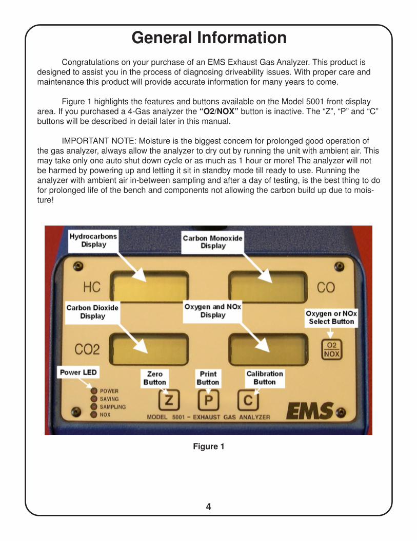
Figure 1 highlights the features and buttons available on the Model 5001 front display
area. If you purchased a 4-Gas analyzer the “O2/NOX” button is inactive. The “Z”, “P” and “C”
buttons will be described in detail later in this manual.
IMPORTANT NOTE: Moisture is the biggest concern for prolonged good operation of
the gas analyzer, always allow the analyzer to dry out by running the unit with ambient air. This
may take only one auto shut down cycle or as much as 1 hour or more! The analyzer will not
be harmed by powering up and letting it sit in standby mode till ready to use. Running the
analyzer with ambient air in-between sampling and after a day of testing, is the best thing to do
for prolonged life of the bench and components not allowing the carbon build up due to mois-
ture!
Figure 1
5
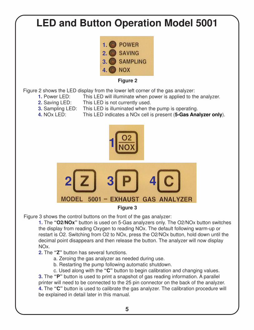
LED and Button Operation Model 5001
Figure 3 shows the control buttons on the front of the gas analyzer:
1. The “O2/NOx” button is used on 5-Gas analyzers only. The O2/NOx button switches
the display from reading Oxygen to reading NOx. The default following warm-up or
restart is O2. Switching from O2 to NOx, press the O2/NOx button, hold down until the
decimal point disappears and then release the button. The analyzer will now display
NOx.
2. The “Z” button has several functions.
a. Zeroing the gas analyzer as needed during use.
b. Restarting the pump following automatic shutdown.
c. Used along with the “C” button to begin calibration and changing values.
3. The “P” button is used to print a snapshot of gas reading information. A parallel
printer will need to be connected to the 25 pin connector on the back of the analyzer.
4. The “C” button is used to calibrate the gas analyzer. The calibration procedure will
be explained in detail later in this manual.
Figure 3
1
2 3 4
1.
2.
3.
4.
Figure 2
Figure 2 shows the LED display from the lower left corner of the gas analyzer:
1. Power LED: This LED will illuminate when power is applied to the analyzer.
2. Saving LED: This LED is not currently used.
3. Sampling LED: This LED is illuminated when the pump is operating.
4. NOx LED: This LED indicates a NOx cell is present (5-Gas Analyzer only).
6
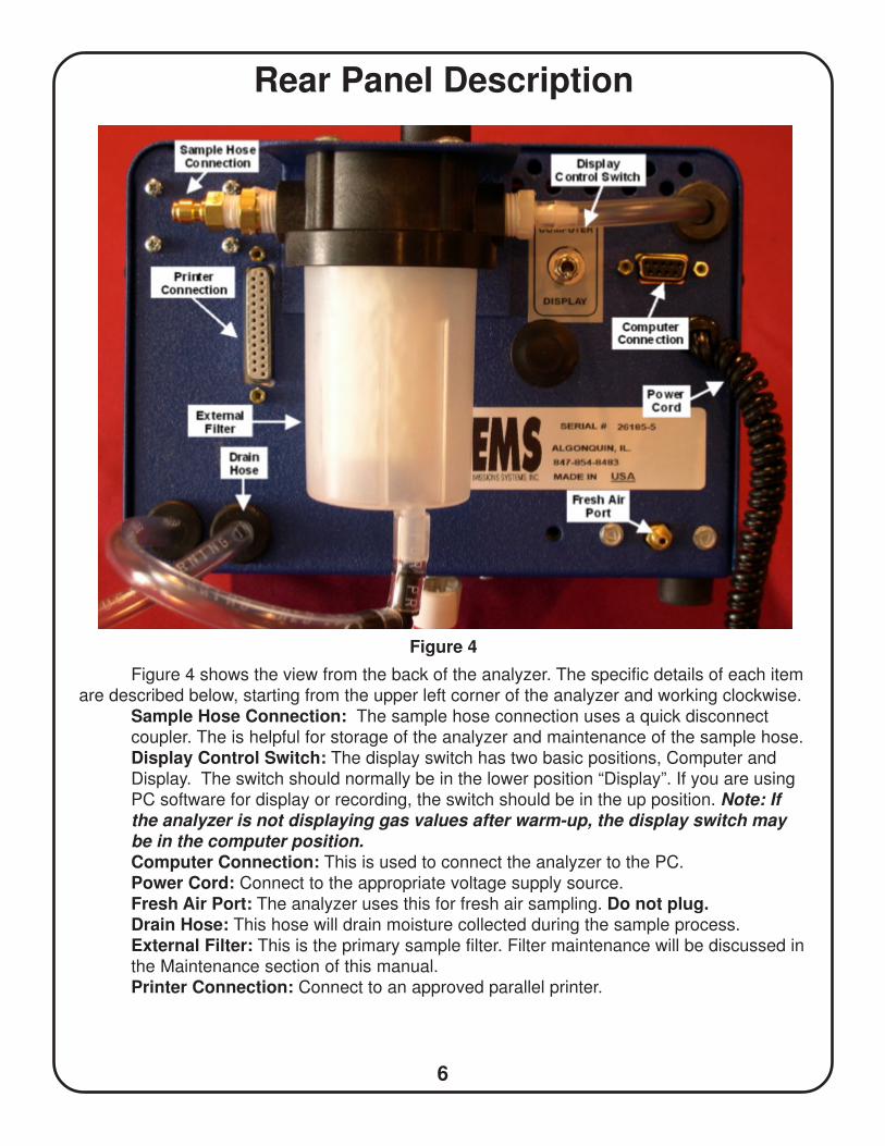
Rear Panel Description
Figure 4 shows the view from the back of the analyzer. The specific details of each item
are described below, starting from the upper left corner of the analyzer and working clockwise.
Sample Hose Connection: The sample hose connection uses a quick disconnect
coupler. The is helpful for storage of the analyzer and maintenance of the sample hose.
Display Control Switch: The display switch has two basic positions, Computer and
Display. The switch should normally be in the lower position “Display”. If you are using
PC software for display or recording, the switch should be in the up position. Note: Ifthe analyzer is not displaying gas values after warm-up, the display switch maybe in the computer position.
Computer Connection: This is used to connect the analyzer to the PC.
Power Cord: Connect to the appropriate voltage supply source.
Fresh Air Port: The analyzer uses this for fresh air sampling. Do not plug.Drain Hose: This hose will drain moisture collected during the sample process.
External Filter: This is the primary sample filter. Filter maintenance will be discussed in
the Maintenance section of this manual.
Printer Connection: Connect to an approved parallel printer.
Figure 4
7
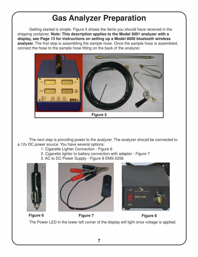
Gas Analyzer Preparation
Getting started is simple. Figure 5 shows the items you should have received in the
shipping container. Note: This description applies to the Model 5001 analyzer with adisplay, see Page 13 for instructions on setting up a Model 8000 bluetooth wirelessanalyzer. The first step is assembling the sample hose. Once the sample hose is assembled,
connect the hose to the sample hose fitting on the back of the analyzer.
Figure 5
The next step is providing power to the analyzer. The analyzer should be connected to
a 12v DC power source. You have several options:
1. Cigarette Lighter Connection - Figure 6
2. Cigarette lighter to battery connection with adapter - Figure 7
3. AC to DC Power Supply - Figure 8 EMS-5256
The Power LED in the lower left corner of the display will light once voltage is applied.
Figure 6 Figure 7 Figure 8
8
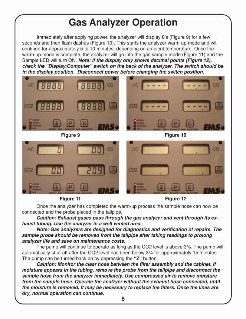
Gas Analyzer Operation
Immediately after applying power, the analyzer will display 8’s (Figure 9) for a few
seconds and then flash dashes (Figure 10). This starts the analyzer warm-up mode and will
continue for approximately 5 to 10 minutes, depending on ambient temperature. Once the
warm-up mode is complete, the analyzer will go into the gas sample mode (Figure 11) and the
Sample LED will turn ON. Note: If the display only shows decimal points (Figure 12),
check the “Display/Computer” switch on the back of the analyzer. The switch should be
in the display position. Disconnect power before changing the switch position.
Figure 9 Figure 10
Figure 11 Figure 12
Once the analyzer has completed the warm-up process the sample hose can now be
connected and the probe placed in the tailpipe.
Caution: Exhaust gases pass through the gas analyzer and vent through its ex-haust tubing. Use the analyzer in a well vented area.
Note: Gas analyzers are designed for diagnostics and verification of repairs. The
sample probe should be removed from the tailpipe after taking readings to prolong
analyzer life and save on maintenance costs.The pump will continue to operate as long as the CO2 level is above 3%. The pump will
automatically shut-off after the CO2 level has been below 3% for approximately 15 minutes.
The pump can be turned back on by depressing the “Z” button.
Caution: Monitor the clear hose between the filter assembly and the cabinet. Ifmoisture appears in the tubing, remove the probe from the tailpipe and disconnect the
sample hose from the analyzer immediately. Use compressed air to remove moisturefrom the sample hose. Operate the analzyer without the exhaust hose connected, until
the moisture is removed. It may be necessary to replace the filters. Once the lines are
dry, normal operation can continue.
9
Gas Analyzer Operation
Manual Zero: Any time after warm-up, you can zero the gas readings and calibrate O2
by pressing the “Z” button. If the pump is off, it will automatically start. Note: The sample
probe should be removed from the tailpipe, when the unit is being zeroed.
Automatic Zero: The analyzer will automatically zero as needed. If the analyzer does
not sense exhaust gases, the automatic zero procedure will begin. The Sample LED will flash
during this process. If exhaust gases are present, the analyzer will wait until the gases are
clear.
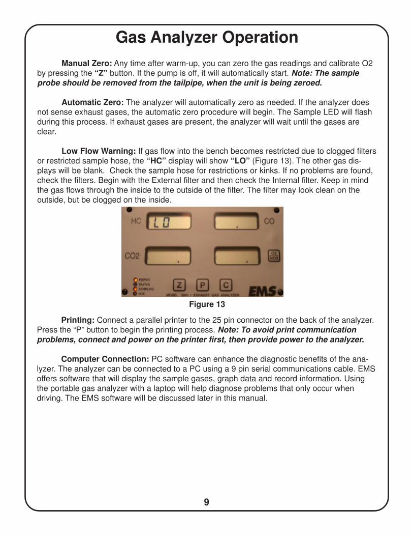
Low Flow Warning: If gas flow into the bench becomes restricted due to clogged filters
or restricted sample hose, the “HC” display will show “LO” (Figure 13). The other gas dis-
plays will be blank. Check the sample hose for restrictions or kinks. If no problems are found,
check the filters. Begin with the External filter and then check the Internal filter. Keep in mind
the gas flows through the inside to the outside of the filter. The filter may look clean on the
outside, but be clogged on the inside.
Figure 13
Printing: Connect a parallel printer to the 25 pin connector on the back of the analyzer.
Press the “P” button to begin the printing process. Note: To avoid print communicationproblems, connect and power on the printer first, then provide power to the analyzer.
Computer Connection: PC software can enhance the diagnostic benefits of the ana-
lyzer. The analyzer can be connected to a PC using a 9 pin serial communications cable. EMS
offers software that will display the sample gases, graph data and record information. Using
the portable gas analyzer with a laptop will help diagnose problems that only occur when
driving. The EMS software will be discussed later in this manual.
10
ERROR CODES
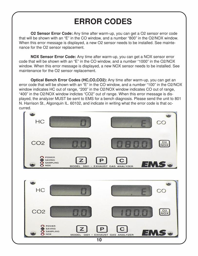
O2 Sensor Error Code: Any time after warm-up, you can get a O2 sensor error code
that will be shown with an “E” in the CO window, and a number “800” in the O2/NOX window.
When this error message is displayed, a new O2 sensor needs to be installed. See mainte-
nance for the O2 sensor replacement.
NOX Sensor Error Code: Any time after warm-up, you can get a NOX sensor error
code that will be shown with an “E” in the CO window, and a number “1000” in the O2/NOX
window. When this error message is displayed, a new NOX sensor needs to be installed. See
maintenance for the O2 sensor replacement.
Optical Bench Error Codes (HC,CO,CO2): Any time after warm-up, you can get an
error code that will be shown with an “E” in the CO window, and a number “100” in the O2/NOX
window indicates HC out of range, “200” in the O2/NOX window indicates CO out of range,
“400” in the O2/NOX window indictes “CO2” out of range. When this error message is dis-
played, the analyzer MUST be sent to EMS for a bench diagnosis. Please send the unit to 801
N. Harrison St., Algonquin IL. 60102, and indicate in writing what the error code is that oc-
curred.
11
Calibration
The gas analyzer should be checked periodically for accuracy. EMS recommends the
analyzer be re-calibrated every 6 months minimum for a 5 gas unit The analyzer can be cali-
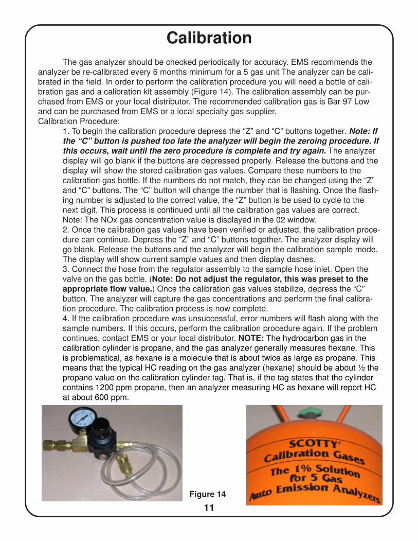
brated in the field. In order to perform the calibration procedure you will need a bottle of cali-
bration gas and a calibration kit assembly (Figure 14). The calibration assembly can be pur-
chased from EMS or your local distributor. The recommended calibration gas is Bar 97 Low
and can be purchased from EMS or a local specialty gas supplier.
Calibration Procedure:
1. To begin the calibration procedure depress the “Z” and “C” buttons together. Note: If
the “C” button is pushed too late the analyzer will begin the zeroing procedure. If
this occurs, wait until the zero procedure is complete and try again. The analyzer
display will go blank if the buttons are depressed properly. Release the buttons and the
display will show the stored calibration gas values. Compare these numbers to the
calibration gas bottle. If the numbers do not match, they can be changed using the “Z”
and “C” buttons. The “C” button will change the number that is flashing. Once the flash-
ing number is adjusted to the correct value, the “Z” button is be used to cycle to the
next digit. This process is continued until all the calibration gas values are correct.
Note: The NOx gas concentration value is displayed in the 02 window.
2. Once the calibration gas values have been verified or adjusted, the calibration proce-
dure can continue. Depress the “Z” and “C” buttons together. The analyzer display will
go blank. Release the buttons and the analyzer will begin the calibration sample mode.
The display will show current sample values and then display dashes.
3. Connect the hose from the regulator assembly to the sample hose inlet. Open the
valve on the gas bottle. (Note: Do not adjust the regulator, this was preset to theappropriate flow value.) Once the calibration gas values stabilize, depress the “C”
button. The analyzer will capture the gas concentrations and perform the final calibra-
tion procedure. The calibration process is now complete.
4. If the calibration procedure was unsuccessful, error numbers will flash along with the
sample numbers. If this occurs, perform the calibration procedure again. If the problem
continues, contact EMS or your local distributor. NOTE: The hydrocarbon gas in the
calibration cylinder is propane, and the gas analyzer generally measures hexane. This
is problematical, as hexane is a molecule that is about twice as large as propane. This
means that the typical HC reading on the gas analyzer (hexane) should be about ½ the
propane value on the calibration cylinder tag. That is, if the tag states that the cylinder
contains 1200 ppm propane, then an analyzer measuring HC as hexane will report HC
at about 600 ppm.
Figure 14
12
Maintenance
Maintenance of the analyzer is essential for accuracy and optimal performance. The
filters, hoses and connections should be checked on a regular basis. Maintenance of the gas
analyzer is simple and only requires a few minutes, but the time you spend will pay off, with
accuracy during the diagnostic process. Specific maintenance procedures are described
below:
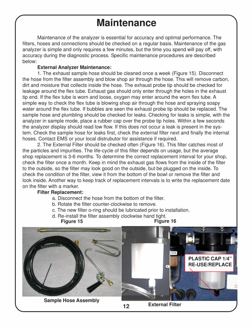
External Analyzer Maintenance:1. The exhaust sample hose should be cleaned once a week (Figure 15). Disconnect
the hose from the filter assembly and blow shop air through the hose. This will remove carbon,
dirt and moisture that collects inside the hose. The exhaust probe tip should be checked for
leakage around the flex tube. Exhaust gas should only enter through the holes in the exhaust
tip end. If the flex tube is worn and loose, oxygen may enter around the worn flex tube. A
simple way to check the flex tube is blowing shop air through the hose and spraying soapy
water around the flex tube. If bubbles are seen the exhaust probe tip should be replaced. The
sample hose and plumbling should be checked for leaks. Checking for leaks is simple, with the
analyzer in sample mode, place a rubber cap over the probe tip holes. Within a few seconds
the analyzer display should read low flow. If this does not occur a leak is present in the sys-
tem. Check the sample hose for leaks first, check the external filter next and finally the internal
hoses. Contact EMS or your local distrubutor for assistance if required.
2. The External Filter should be checked often (Figure 16). This filter catches most of
the particles and impurities. The life-cycle of this filter depends on usage, but the average
shop replacement is 3-6 months. To determine the correct replacement interval for your shop,
check the filter once a month. Keep in mind the exhaust gas flows from the inside of the filter
to the outside, so the filter may look good on the outside, but be plugged on the inside. To
check the condition of the filter, view it from the bottom of the bowl or remove the filter and
look inside. Another way to keep track of replacement intervals is to write the replacement date
on the filter with a marker.
Filter Replacement:a. Disconnect the hose from the bottom of the filter.
b. Rotate the filter counter-clockwise to remove.
c. The new filter o-ring should be lubricated prior to installation.
d. Re-install the filter assembly clockwise hand tight.
External FilterSample Hose Assembly
Figure 15 Figure 16
PLASTIC CAP 1/4”RE-USE/REPLACE
13
Maintenance
Internal Analyzer Maintenance:The maintenance items discussed below are located inside the analyzer. The outside
cover will need to be removed to gain access. The cover is held in place with 11 screws, 5 on
each side panel and one at the top behind the handle.
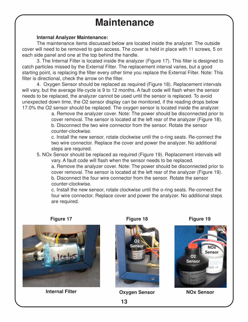
3. The Internal Filter is located inside the analyzer (Figure 17). This filter is designed to
catch particles missed by the External Filter. The replacement interval varies, but a good
starting point, is replacing the filter every other time you replace the External Filter. Note: This
filter is directional, check the arrow on the filter.
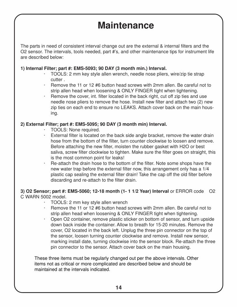
4. Oxygen Sensor should be replaced as required (Figure 18). Replacement intervals
will vary, but the average life-cycle is 9 to 12 months. A fault code will flash when the sensor
needs to be replaced, the analyzer cannot be used until the sensor is replaced. To avoid
unexpected down time, the O2 sensor display can be monitored, if the reading drops below
17.0% the O2 sensor should be replaced. The oxygen sensor is located inside the analyzer.
a. Remove the analyzer cover. Note: The power should be disconnected prior to
cover removal. The sensor is located at the left rear of the analyzer (Figure 18).
b. Disconnect the two wire connector from the sensor. Rotate the sensor
counter-clockwise.
c. Install the new sensor, rotate clockwise until the o-ring seats. Re-connect the
two wire connector. Replace the cover and power the analyzer. No additional
steps are required.
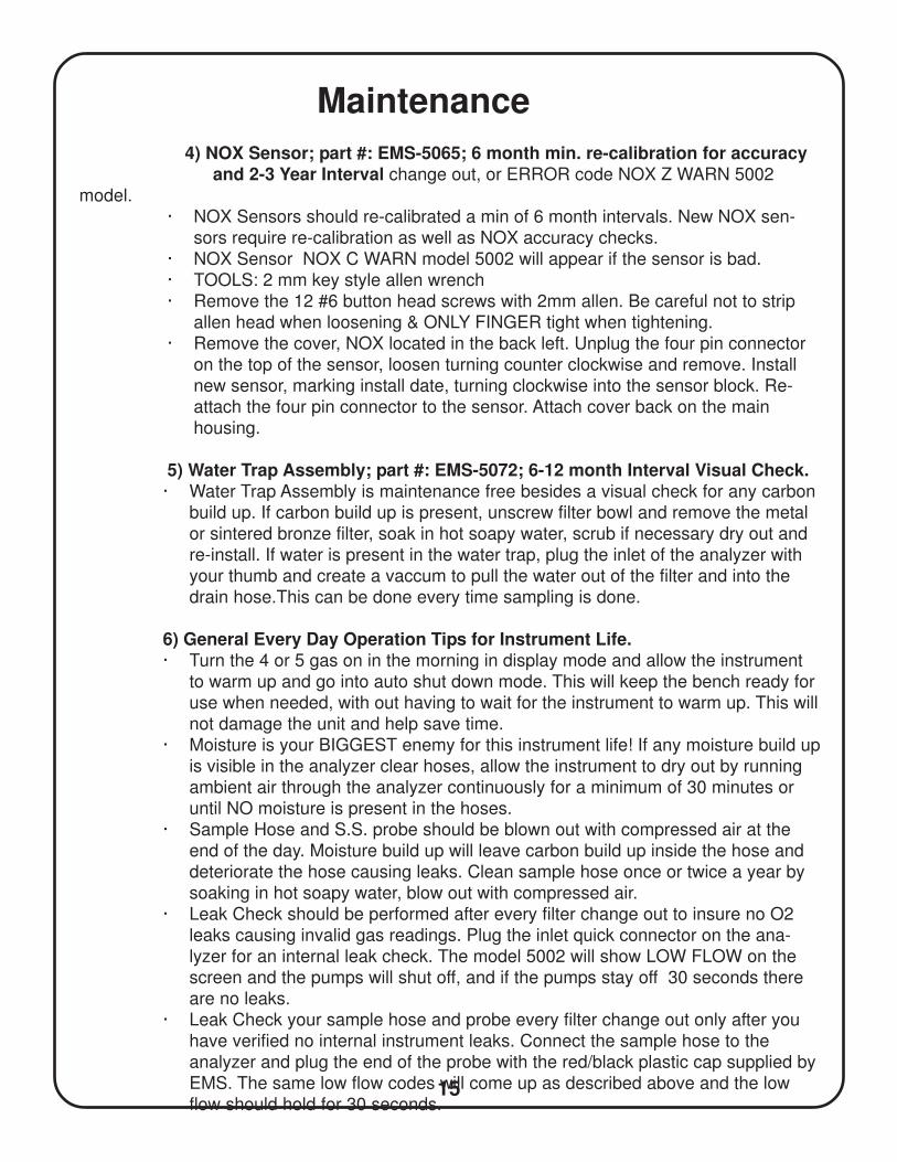
5. NOx Sensor should be replaced as required (Figure 19). Replacement intervals will
vary. A fault code will flash when the sensor needs to be replaced.
a. Remove the analyzer cover. Note: The power should be disconnected prior to
cover removal. The sensor is located at the left rear of the analyzer (Figure 19).
b. Disconnect the four wire connector from the sensor. Rotate the sensor
counter-clockwise.
c. Install the new sensor, rotate clockwise until the o-ring seats. Re-connect the
four wire connector. Replace cover and power the analyzer. No additional steps
are required.
Figure 18Figure 17
Internal Filter Oxygen Sensor
Figure 19
NOx Sensor
NOxSensor
O2Sensor
O2Sensor
14
Maintenance
The parts in need of consistent interval change out are the external & internal filters and the
O2 sensor. The intervals, tools needed, part #’s, and other maintenance tips for instrument life
are described below:
1) Internal Filter; part #: EMS-5093; 90 DAY (3 month min.) Interval.· TOOLS: 2 mm key style allen wrench, needle nose pliers, wire/zip tie strap
cutter .
· Remove the 11 or 12 #6 button head screws with 2mm allen. Be careful not to
strip allen head when loosening & ONLY FINGER tight when tightening.
· Remove the cover, int. filter located in the back right, cut off zip ties and use
needle nose pliers to remove the hose. Install new filter and attach two (2) new
zip ties on each end to ensure no LEAKS. Attach cover back on the main hous-
ing.
2) External Filter; part #: EMS-5095; 90 DAY (3 month min) Interval.· TOOLS: None required.
· External filter is located on the back side angle bracket, remove the water drain
hose from the bottom of the filter, turn counter clockwise to loosen and remove.
Before attaching the new filter, moisten the rubber gasket with H2O or best
saliva, screw filter clockwise to tighten. Make sure the filter goes on straight, this
is the most common point for leaks!
· Re-attach the drain hose to the bottom of the filter. Note some shops have the
new water trap before the external filter now, this arrangement only has a 1/4
plastic cap sealing the external filter drain! Take the cap off the old filter before
discarding and re-attach to the filter drain.
3) O2 Sensor; part #: EMS-5060; 12-18 month (1- 1 1/2 Year) Interval or ERROR code O2
C WARN 5002 model.
· TOOLS: 2 mm key style allen wrench
· Remove the 11 or 12 #6 button head screws with 2mm allen. Be careful not to
strip allen head when loosening & ONLY FINGER tight when tightening.
· Open O2 container, remove plastic sticker on bottom of sensor, and turn upside
down back inside the container. Allow to breath for 15-20 minutes. Remove the
cover, O2 located in the back left. Unplug the three pin connector on the top of
the sensor, loosen turning counter clockwise and remove. Install new sensor,
marking install date, turning clockwise into the sensor block. Re-attach the three
pin connector to the sensor. Attach cover back on the main housing.
These three items must be regularly changed out per the above intervals. Other
items not as critical or more complicated are described below and should be
maintained at the intervals indicated.
15
Maintenance
4) NOX Sensor; part #: EMS-5065; 6 month min. re-calibration for accuracy and 2-3 Year Interval change out, or ERROR code NOX Z WARN 5002
model.
· NOX Sensors should re-calibrated a min of 6 month intervals. New NOX sen-
sors require re-calibration as well as NOX accuracy checks.
· NOX Sensor NOX C WARN model 5002 will appear if the sensor is bad.
· TOOLS: 2 mm key style allen wrench
· Remove the 12 #6 button head screws with 2mm allen. Be careful not to strip
allen head when loosening & ONLY FINGER tight when tightening.
· Remove the cover, NOX located in the back left. Unplug the four pin connector
on the top of the sensor, loosen turning counter clockwise and remove. Install
new sensor, marking install date, turning clockwise into the sensor block. Re-
attach the four pin connector to the sensor. Attach cover back on the main
housing.
5) Water Trap Assembly; part #: EMS-5072; 6-12 month Interval Visual Check.· Water Trap Assembly is maintenance free besides a visual check for any carbon
build up. If carbon build up is present, unscrew filter bowl and remove the metal
or sintered bronze filter, soak in hot soapy water, scrub if necessary dry out and
re-install. If water is present in the water trap, plug the inlet of the analyzer with
your thumb and create a vaccum to pull the water out of the filter and into the
drain hose.This can be done every time sampling is done.
6) General Every Day Operation Tips for Instrument Life.· Turn the 4 or 5 gas on in the morning in display mode and allow the instrument
to warm up and go into auto shut down mode. This will keep the bench ready for
use when needed, with out having to wait for the instrument to warm up. This will
not damage the unit and help save time.
· Moisture is your BIGGEST enemy for this instrument life! If any moisture build up
is visible in the analyzer clear hoses, allow the instrument to dry out by running
ambient air through the analyzer continuously for a minimum of 30 minutes or
until NO moisture is present in the hoses.
· Sample Hose and S.S. probe should be blown out with compressed air at the
end of the day. Moisture build up will leave carbon build up inside the hose and
deteriorate the hose causing leaks. Clean sample hose once or twice a year by
soaking in hot soapy water, blow out with compressed air.
· Leak Check should be performed after every filter change out to insure no O2
leaks causing invalid gas readings. Plug the inlet quick connector on the ana-
lyzer for an internal leak check. The model 5002 will show LOW FLOW on the
screen and the pumps will shut off, and if the pumps stay off 30 seconds there
are no leaks.
· Leak Check your sample hose and probe every filter change out only after you
have verified no internal instrument leaks. Connect the sample hose to the
analyzer and plug the end of the probe with the red/black plastic cap supplied by
EMS. The same low flow codes will come up as described above and the low
flow should hold for 30 seconds.
16
· Leak check failures would be if the 5002 model pumps turn on during the 30
seconds. The most common leak location is at the external filter head, this can
be check with a butane lighter to see if your HC reading increases. Make sure
the filter is screwed on straight and the O-Ring is moistened. If the leak is at the
internal filter, twist the filter in the hose and make sure zip tie is tight or replace.
If a leak is found in the sample hose or probe, ORDER NEW parts. Sample
Hose part #: EMS-5096-25, Handle part #: EMS-5097, S.S. Probe part #: EMS-
5098.
· Two Cycle gasoline testing: Two cycle fuel is much more of a maintenance
issue than standard gasoline or diesel testing. In order to determine a good
maintenance schedule, check the filters once a week with a visual inspection. If
a yellowish build up in the external filter is present, this is oil contamination, and
will possibly give you inaccurate readings due to HC residual build up. This
would be seen after ZEROING the unit, and HC readings being displayed with-
out taking an exhaust sample. This would indicate filter change out is required.
For the pre-filter water trap sintered bronze filter, any yellowish or oil build up
would require cleaning with hot soapy water. Make notes of how many tests
have been preformed so you can get a bench mark for your filter change out or
cleaning. If you are not changing out and cleaning the filters, this could result in
a bench failure due to oil contamination build up inside the IR bench. Also be
careful of how long you sample this exhaust. A longer test can result in contami-
nation, so only allow the unit to sample as long as needed, and afterwards,
always allow the unit to purge out any contamination by running fresh air for as
long as possible, or a minimum of 15 minutes or auto shut down in stand by
mode. This is the best thing to do after sampling any engine and will prolong the
analyzer component life.
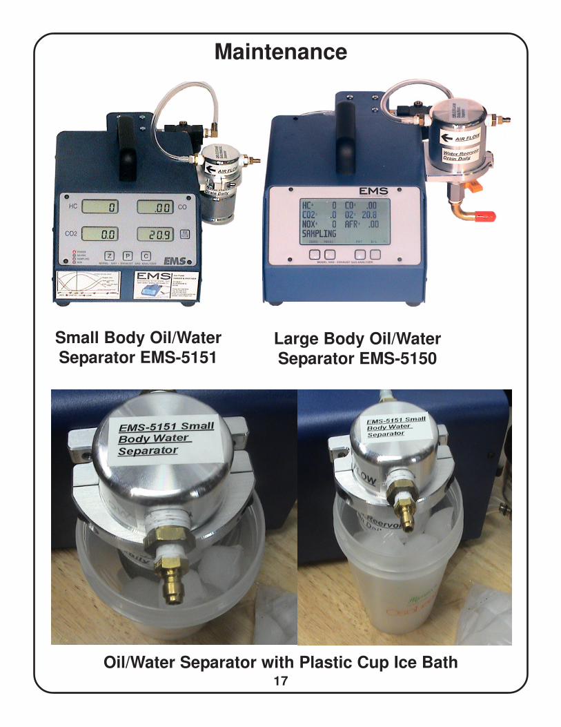
OIL/WATERSEPARATOR: The new High Performance Oil Water Separator,
EMS-5151, has been added to remove more oil/water before the automatic drain
water trap assembly. The separator should be drained daily by unscrewing the
oil/water reservoir daily. The Large Body Separator, EMS-5150, has a ball valve
drain The separator will work better in colder weather, to enhance the capability
of the separator in hot humid weather, EMS recommends to make a home made
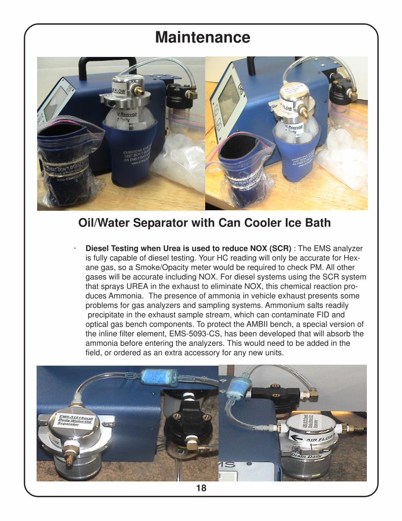
oil/water condensor by attaching a ICE bath. This can be done with a plastic cup
filled with ice around the reservoir, or you can use a can cooler with a plastic
sandwich bag around it to hold the melted water. This simple trick will be very
effective in pulling more moisture out of the sample , very similar to the official
state run facilities with DYNO testing. Give it a try and you will see a huge
difference! See pg, 19 & 20 for detail pictures.
Maintenance
17
Maintenance
Large Body Oil/WaterSeparator EMS-5150
Small Body Oil/WaterSeparator EMS-5151
Oil/Water Separator with Plastic Cup Ice Bath
18
Maintenance
Oil/Water Separator with Can Cooler Ice Bath
· Diesel Testing when Urea is used to reduce NOX (SCR) : The EMS analyzeris fully capable of diesel testing. Your HC reading will only be accurate for Hex-
ane gas, so a Smoke/Opacity meter would be required to check PM. All other
gases will be accurate including NOX. For diesel systems using the SCR system
that sprays UREA in the exhaust to eliminate NOX, this chemical reaction pro-
duces Ammonia. The presence of ammonia in vehicle exhaust presents some
problems for gas analyzers and sampling systems. Ammonium salts readily
precipitate in the exhaust sample stream, which can contaminate FID and
optical gas bench components. To protect the AMBII bench, a special version of
the inline filter element, EMS-5093-CS, has been developed that will absorb the
ammonia before entering the analyzers. This would need to be added in the
field, or ordered as an extra accessory for any new units.
19
Maintenance
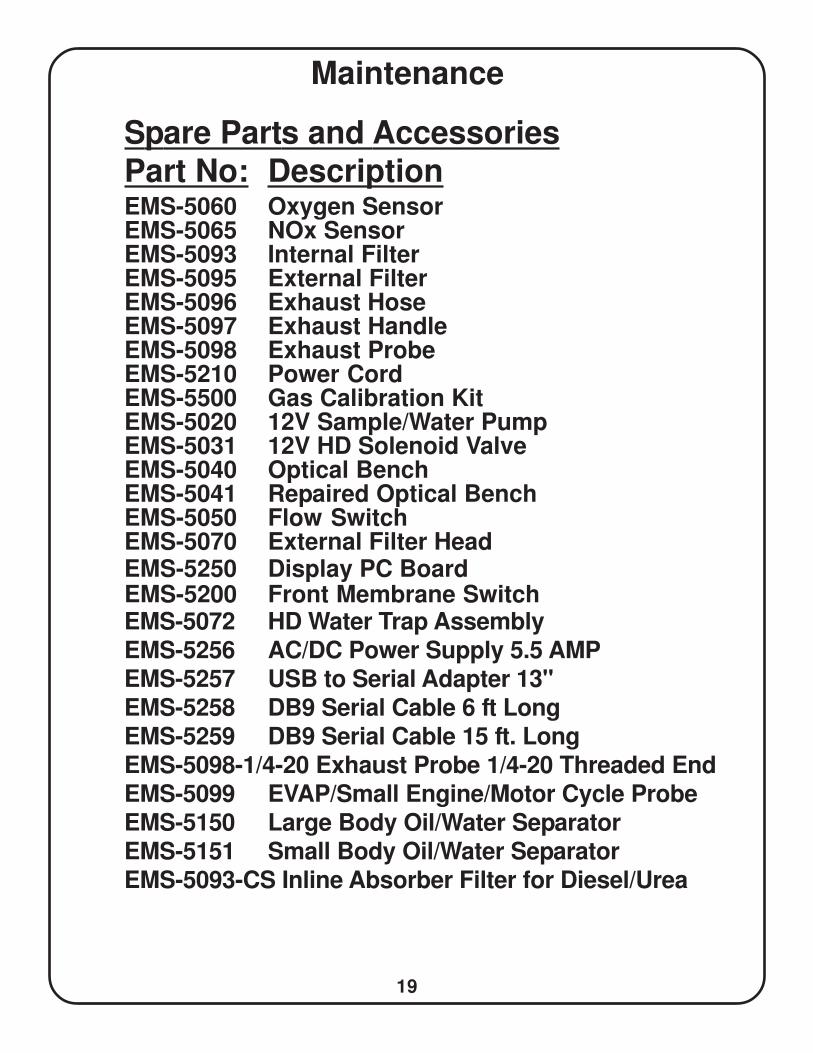
Spare Parts and AccessoriesPart No: DescriptionEMS-5060 Oxygen SensorEMS-5065 NOx SensorEMS-5093 Internal FilterEMS-5095 External FilterEMS-5096 Exhaust HoseEMS-5097 Exhaust HandleEMS-5098 Exhaust ProbeEMS-5210 Power CordEMS-5500 Gas Calibration KitEMS-5020 12V Sample/Water PumpEMS-5031 12V HD Solenoid ValveEMS-5040 Optical BenchEMS-5041 Repaired Optical BenchEMS-5050 Flow SwitchEMS-5070 External Filter HeadEMS-5250 Display PC BoardEMS-5200 Front Membrane SwitchEMS-5072 HD Water Trap AssemblyEMS-5256 AC/DC Power Supply 5.5 AMPEMS-5257 USB to Serial Adapter 13"EMS-5258 DB9 Serial Cable 6 ft LongEMS-5259 DB9 Serial Cable 15 ft. LongEMS-5098-1/4-20 Exhaust Probe 1/4-20 Threaded EndEMS-5099 EVAP/Small Engine/Motor Cycle ProbeEMS-5150 Large Body Oil/Water SeparatorEMS-5151 Small Body Oil/Water SeparatorEMS-5093-CS Inline Absorber Filter for Diesel/Urea
20
Diagnostic Accessories
Figure 1 Figure 2 Figure 3
Figure 4 Figure 5
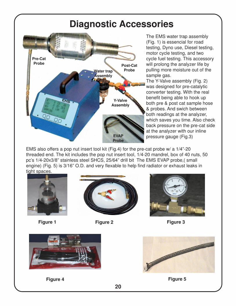
The EMS water trap assembly
(Fig. 1) is essencial for road
testing, Dyno use, Diesel testing,
motor cycle testing, and two
cycle fuel testing. This accessory
will prolong the analyzer life by
pulling more moisture out of the
sample gas.
The Y-Valve assembly (Fig. 2)
was designed for pre-catalytic
converter testing. With the real
benefit being able to hook up
both pre & post cat sample hose
& probes. And swich between
both readings at the analyzer,
which saves you time. Also check
back pressure on the pre-cat side
at the analyzer with our inline
pressure gauge (Fig.3)
EMS also offers a pop nut insert tool kit (Fig.4) for the pre-cat probe w/ a 1/4”-20threaded end. The kit includes the pop nut insert tool, 1/4-20 mandrel, box of 40 nuts, 50
pc’s 1/4-20x3/8” stainless steel SHCS, 25/64” drill bit The EMS EVAP probe,( small
engine) (Fig. 5) is 3/16” O.D. and very flexable to help find radiator or exhaust leaks in
tight spaces.
Pre-CatProbe
Post-CatProbe
EVAPProbe
Water trapAssembly
Y-ValveAssembly
21
DiagnosticsExhaust gas analyzers can be used to diagnose driveability concerns, ignition system
problems, fuel management issues, engine mechanical problems, excessive emissions prob-
lems and many other vehicle systems. Vehicle inspection and preparation are the keys to
getting the most out of your gas analyzer.
1. A visual inspection should include; vacuum hoses, air filter, exhaust system,
air management system, emission related components, etc. If the malfunction
indicator light (MIL) is illuminated, check the diagnostic trouble codes (DTC’s)
prior to testing.
2. Vehicle preparation:
a. The engine should be at operating temperature prior to testing.
b. Start the engine and run until the cooling fan cycles on and off. Another
option is using a scan tool to check the engine coolant temperature (ECT).
The temperature should exceed 190 degree F.
c. After the engine is warm, increase the engine speed to 2500 RPM for
approximately 60 seconds.
d. Return the engine speed to idle.
e. Insert the sample probe and begin your diagnostics.
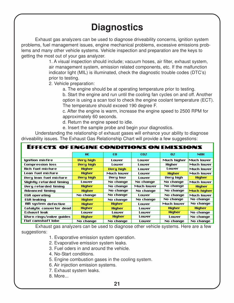
Understanding the relationship of exhaust gases will enhance your ability to diagnose
driveability issues. The Exhaust Gas Relationship Chart will provide a few suggestions:
Exhaust gas analyzers can be used to diagnose other vehicle systems. Here are a few
suggestions:
1. Evaporative emission system operation.
2. Evaporative emission system leaks.
3. Fuel oders in and around the vehicle.
4. No-Start conditions.
5. Engine combustion gases in the cooling system.
6. Air injection emission systems.
7. Exhaust system leaks.
8. More...
22
Warranty
• Emission Systems products are guaranteed to be free of defects in material and
workmanship to the original purchaser, for a period of one year from the date of
purchase. Probes and electrical leads are warranted for ninety days. The optical
bench is warranted for 1 Year.
• This warranty does not apply to products which have been:
1) Altered
2) Improperly installed, maintained or repaired.
3) Damaged by accident, negligence or misuse.
• THIS WARRANTY EXCLUDES ALL INCIDENTAL OR CONSEQUENTIALDAMAGES
• If you suspect there is a problem with your unit, the operating manual should be
reviewed first. Your particular problem may be covered in the operating instruc-
tions. If the issue cannot be resolved, contact EMS or your authorized distributor
for additional information. If the unit requires repair, contact EMS to obtain a Re-
turn Authorization Number. The unit should be properly packaged and should
include all accessories. The customer is responsible for shipping the unit back to
EMS for warranty repair.The unit should be returned in the shortest possible
timeframe at customers cost, EMS will return the unit with the same shipping
• In the USA and Canada call: 847-669-8044 for assistance.
• Outside USA call your authorized distributor for assistance.
Warranty Information:
• Date of Purchase: ____________
• Serial Number: ______________


