Download - PORTABLE AFTERCOOLER - Continental Carbonic

AFTERCOOLER OPERATION MANUALMODEL CA-700 PORTABLE AFTERCOOLER/FILTER
PORTABLE AFTERCOOLER
™
Aftercooler Operation Manual
2Rev. 6/11/14
Suitable for most blasting applications, the Command Air 700 efficiently cools, filters and dries the hot moist air produced by air compressors. Built tough for portable applications, the Command Air 700 features self-purging auto-matic drains, robust steel frame and airless tires for easy mobility.
APPLICATIONS:• Dry Ice Cleaning• Sand Blasting• Soda Blasting• Any other equipment requiring cool, dry air for operation
1.0 INTRODUCTION
Command Air Aftercoolers are guaranteed to be free of defects in material and / or workmanship for two (2) Years from the date of shipment to the buyer. The warranty shall cover 100% of all parts and labor with the exception of misuse, abuse, or neglect. The warranty also does not cover consumable items such as filters, drains and separators.
The manufacturer will at it’s option repair, replace or issue credit for the value of any defective aftercooler. Failure to follow proper operation and maintenance procedures described in this manual may limit or void this warranty.
Buyer accepts all responsibility for compliance with any / all Local, State and Federal Laws or Regulations including Regulations of Foreign Governments.
No equipment shall be returned without a Return Authorization Number from our customer service department. Upon evaluation and determination of warranty, replacements or repairs will be sent to the buyer. If a replacement is needed immediately, a Purchase Order is required to cover the cost of the product until the warranty is determined.
The warranty is limited to replacing any goods that are proved to be defective and the manufacturer in no event shall have any liability for paying incidental or consequential damages including and without limitation, damages resulting in personal or bodily injury or death, or damages to, or loss of use of any property. Notwithstanding any of these terms and conditions, the warranty set forth shall apply in connection with any sales of goods, services or design by the manufacturer and are in lieu of all warranties, express or implied, including warranties of merchantability and fitness for a particular purpose.
As with all equipment using a high pressure air source, proper eye and ear protection, along protective gloves, are required while operating the aftercooler. Do not touch inlet piping without protective gloves, air coming in from the compressor can be extremely hot and could cause minor burns. Review this operation manual prior to operation to ensure proper setup and safety procedures are followed.
1.1 WARRANTY
1.2 SAFETY PRECAUTIONS
3
Aftercooler Operation Manual
Rev. 6/11/14
CA-700 Aftercooler Specifications:• Pressure Rating: 232 psi MAX• Max inlet temperature: 250°F• Flow Capacity: 466 CFM @ 100 psi, 704 CFM @ 232 psi MAX• Filtration: Coalescing grade 10 (.7 micron)• Dimensions: 48” tall x 26.6” wide x 18.75” deep• Weight: 205 lbs• Inlet: 1.5” female NPT• Outlet: 1.5” female NPT• Fan Motor Supply: 25 CFM @ 35 psi MAX
1.3 MACHINE SPECIFICATIONS
2.0 OPERATION
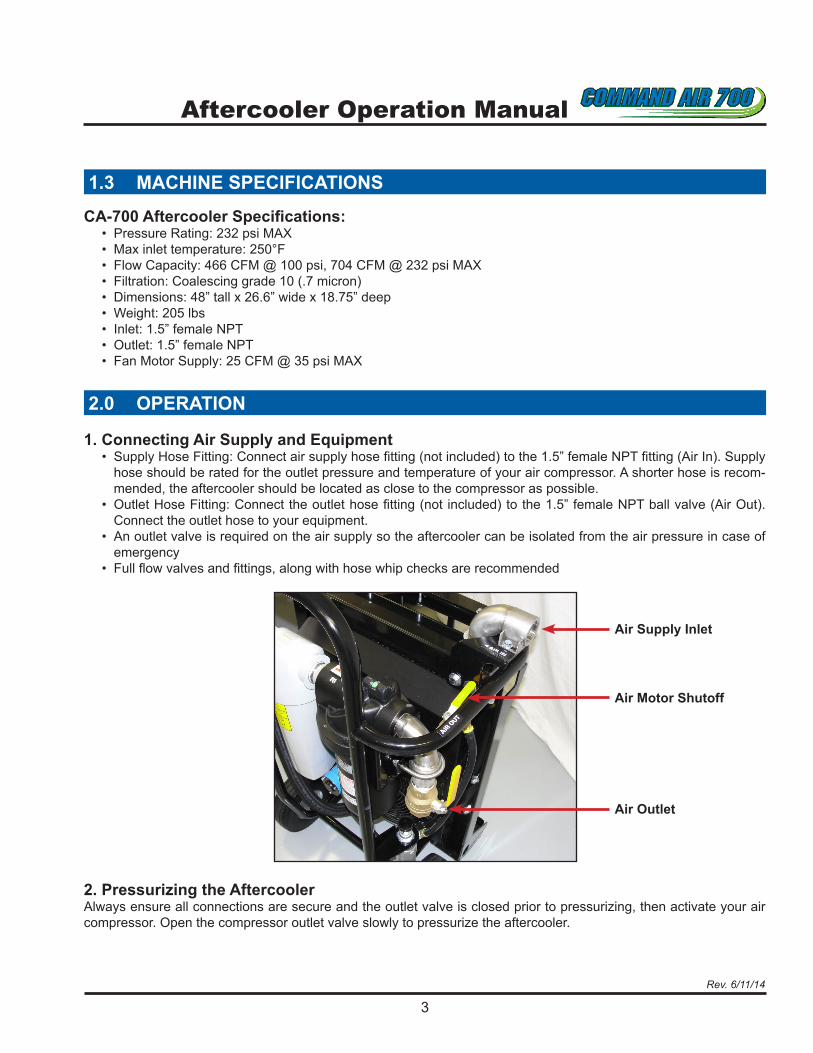
1. Connecting Air Supply and Equipment• Supply Hose Fitting: Connect air supply hose fitting (not included) to the 1.5” female NPT fitting (Air In). Supply
hose should be rated for the outlet pressure and temperature of your air compressor. A shorter hose is recom-mended, the aftercooler should be located as close to the compressor as possible.
• Outlet Hose Fitting: Connect the outlet hose fitting (not included) to the 1.5” female NPT ball valve (Air Out). Connect the outlet hose to your equipment.
• An outlet valve is required on the air supply so the aftercooler can be isolated from the air pressure in case of emergency
• Full flow valves and fittings, along with hose whip checks are recommended
2. Pressurizing the AftercoolerAlways ensure all connections are secure and the outlet valve is closed prior to pressurizing, then activate your air compressor. Open the compressor outlet valve slowly to pressurize the aftercooler.
Air Outlet
Air Motor Shutoff
Air Supply Inlet
Aftercooler Operation Manual
4Rev. 6/11/14
2.0 OPERATION (continued)
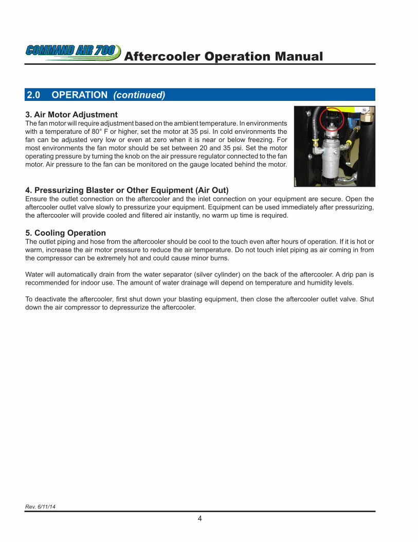
3. Air Motor AdjustmentThe fan motor will require adjustment based on the ambient temperature. In environments with a temperature of 80° F or higher, set the motor at 35 psi. In cold environments the fan can be adjusted very low or even at zero when it is near or below freezing. For most environments the fan motor should be set between 20 and 35 psi. Set the motor operating pressure by turning the knob on the air pressure regulator connected to the fan motor. Air pressure to the fan can be monitored on the gauge located behind the motor.
4. Pressurizing Blaster or Other Equipment (Air Out)Ensure the outlet connection on the aftercooler and the inlet connection on your equipment are secure. Open the aftercooler outlet valve slowly to pressurize your equipment. Equipment can be used immediately after pressurizing, the aftercooler will provide cooled and filtered air instantly, no warm up time is required.
5. Cooling OperationThe outlet piping and hose from the aftercooler should be cool to the touch even after hours of operation. If it is hot or warm, increase the air motor pressure to reduce the air temperature. Do not touch inlet piping as air coming in from the compressor can be extremely hot and could cause minor burns.
Water will automatically drain from the water separator (silver cylinder) on the back of the aftercooler. A drip pan is recommended for indoor use. The amount of water drainage will depend on temperature and humidity levels.
To deactivate the aftercooler, first shut down your blasting equipment, then close the aftercooler outlet valve. Shut down the air compressor to depressurize the aftercooler.

5
Aftercooler Operation Manual
Rev. 6/11/14
3.0 MAINTENANCE & PARTS
Coalescing Filter• Check the differencial pressure (DP) indicator on the top of the coalescing filter periodically to view the
status of the filter element. The indicator will show red when it is time to change the filter element.
Water Separator• The water separator is for the most part maintenance free, however it should be inspected for proper
operation. If it is not separating moisture from the air it may need to be replaced or the drain may be clogged.
Moisture Drains• The four drains may be cleaned or replaced as needed. The automatic drain on the water separator will
drain the most water. If it stops draining for an extended period of time, check for a clogged drain and clean.
Cooler & Air Motor• The air motor powering the cooler is oilless and should not require maintenance. The fan and vents on the
cooler should be inspected regularly and will require cleaning when dirty. The fan unit may be cleaned with compressed air or a power washer. If power washing, be sure to spray the unit parallel to the direction of the fan blades in order to avoid damage.
Coalescing Filter
DP Indicator
Filter Drain
Pulse Drain
Water Separator
Cooler Motor
Automatic Drain
Cooler Pulse Drain

Aftercooler Components
6Rev. 6/11/14
CAC12AI51
CAC12F501
CAC12F029A
CAC12F509
SEE DRAWING # 2(CAC12AOF50)
CAC12F508AIR OUT FILTER ASSEMBLY DETAIL
CAC12FA500
CAC12GA001TOP VIEWREVISED 03/10/14
DRAWING #1 OF 5
REVISED 03/10/14
DRAWING #2 OF 5
CAC12F517
(SCREW IN)
(SCREW IN)
CAC12F515CAC12F511
1 1/2"
NIPPLE
WELDED ASSEMBLY CAC12AOF54WELDED ASSEMBLY
CAC12AOF53
CAC12AOF52 CAC12AOF51
CAC12F514

Aftercooler Components
7Rev. 6/11/14
CAC12F511CAC12AOF55
CAC12F064
IB10B26
CAC12F501
CAC12FA500
LEFT SIDE VIEW
CAC12F059A
CAC12F521
CAC12GA001
CAC12F053A
CAC12AI51WELDED ASSEMBLY
RIGHT SIDE VIEW
REVISED 03/10/14DRAWING #4 OF 5
REVISED 03/10/14DRAWING #3 OF 5

Aftercooler Components
8Rev. 6/11/14
CAC12F029A
CAC12F509
CAC12F060
CAC12F012A
WELDED ASSEMBLY
CAC12F517
WELDED ASSEMBLYCAC12AOF54
CAC12F520
CAC12F519
CAC12F518
CAC12AOF55
CAC12F511
WELDED ASSEMBLYCAC12AOF53
CAC12AI51
CAC12AOF50
REAR VIEW
REVISED 03/10/14
DRAWING #5 OF 5

Aftercooler Components
9Rev. 6/11/14
1CAC12FAI51 AIR IN PIPE ASSEMBLY W/BRKT & BOLTS
FAN AIR MOTOR W/SPACER & BOLTS
11CAC12F5211BALL VALVE - MOTOR CONTROLCAC12F053A
CAC12F520
HOSE ASSEMBLY W/FITTINGS - VALVE TO REGULATOR
HOSE ASSEMBLY W/FITTINGS - REGULATOR TO FAN MOTOR 1
CAC12F059A FILTER/REGULATOR-3/8" PORTS (250 PSI)
TEE FITTING - AIR MOTOR
CAC12F029A AIR IN PIPE BRKT W/BOLTS 1
CAC12F518CAC12F519
CAC12AOF55GAUGE - AIR MOTOR SUPPLY
HOSE ASSEMBLY - FILTER SUPPLY 111
AIR OUT PIPE ASSEMBLYCAC12AOF54 1
CAC12F501 RADIATOR ASSEMBLY W/FAN BLADE & SHROUD 1
CAC12F060 NYLOC NUT - WHEEL RETAININGCAC12F06410" SOLID WHEELS
CAC12AOF55IB10B26
AIR OUT PIPE ASSEMBLY
21
12
AIR OUT CONNECTING NIPPLECAC12F515DISCHARGE BALL VALVE
AIR IN JIC FITTING 2CAC12F511
1CAC12F5171
CAC12AOF51 1COALESCING FILTER ASSEMBLY
AIR OUT PIPE ASSEMBLYCAC12AOF53WATER SEPARATOR FILTER ASSEMBLYCAC12AOF52NIPPLE - FILTER TO SEPARATORCAC12F514 1
11
AIR OUT FILTER ASSEMBLYCAC12AOF50
2" U BOLT 111
CAC12F508CAC12F509 2 1/2" U BOLT
# PER EA.DESCRIPTION PART #
CAC12F012A RADIATOR MOUNTING BRKT W/BOLTS
111
MACHINE
CAC12GA001CAC12FA500 TUBING FRAME ASSEMBLY W/WELD ON BRACKETS - LARGE COOLER
RADIATOR GUARD ASSEMBLY W/BOLTS
REVISED 03/05/14
COMPONENTS LIST - AFTERCOOLER (CA-700)

TO ORDER BLASTING DRY ICE OR FOR SERVICE CALL:
1-800-DRY-ICE2www.continentalcarbonic.com
For a full product line please visit www.continentalcarbonic.com.


