32
Codificación de producto / Product codification
AmperiosAmpers
Serie / SerieS5- / S5B /S5D /S5F /S5L /S5M /S5S
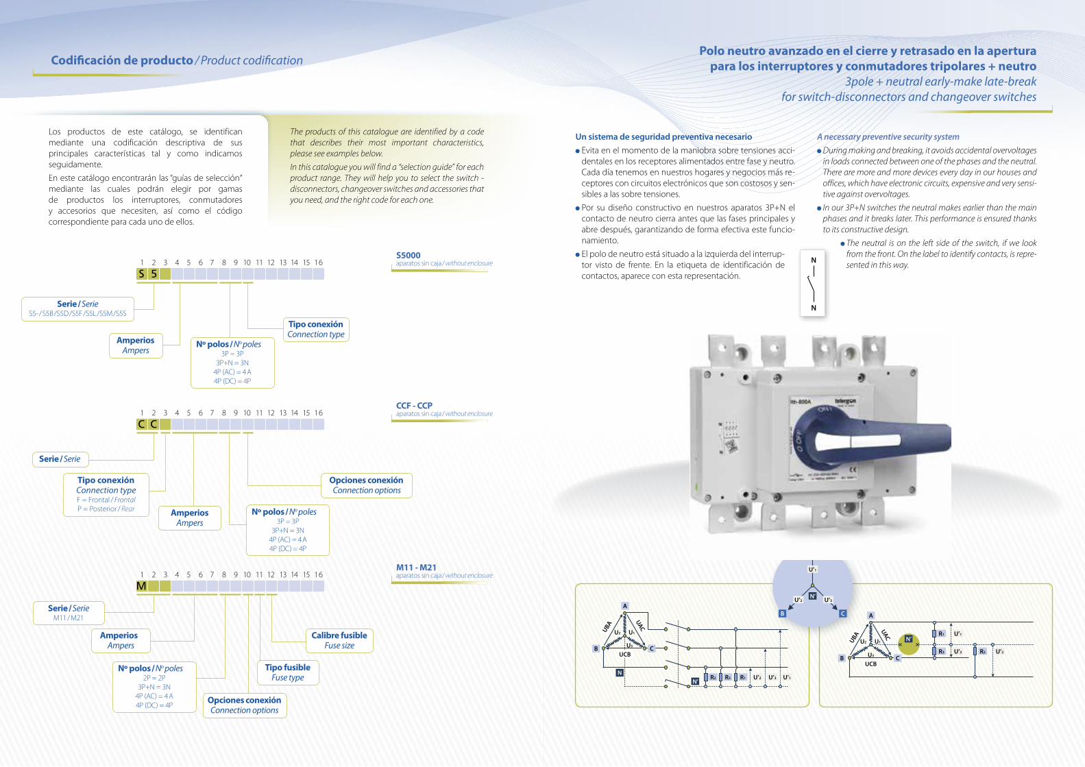
S 5 1 2 3 4 5 6 7 8 9 10 11 12 13 14 15 16
Nº polos / No poles3P = 3P
3P+N = 3N4P (AC) = 4 A4P (DC) = 4P
Tipo conexiónConnection type
S5000 aparatos sin caja / without enclosure
Tipo conexiónConnection typeF = Frontal / FrontalP = Posterior / Rear
Serie / Serie
C C 1 2 3 4 5 6 7 8 9 10 11 12 13 14 15 16
AmperiosAmpers
CCF - CCP aparatos sin caja / without enclosure
Opciones conexiónConnection options
AmperiosAmpers
Serie / SerieM11 / M21
M 1 2 3 4 5 6 7 8 9 10 11 12 13 14 15 16
M11 - M21 aparatos sin caja / without enclosure
Tipo fusibleFuse type
Calibre fusibleFuse size
Opciones conexiónConnection options
Nº polos / No poles3P = 3P
3P+N = 3N4P (AC) = 4 A4P (DC) = 4P
Nº polos / No poles2P = 2P
3P+N = 3N4P (AC) = 4 A4P (DC) = 4P
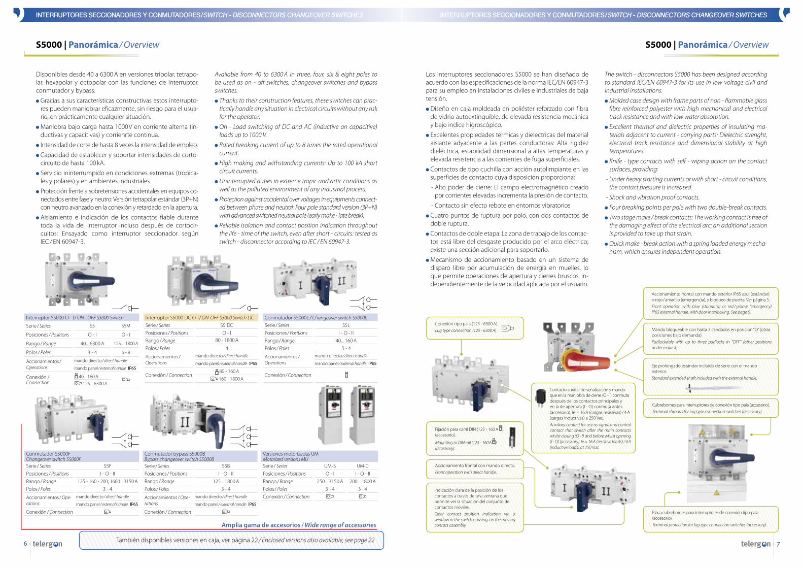
Un sistema de seguridad preventiva necesario Evita en el momento de la maniobra sobre tensiones acci-dentales en los receptores alimentados entre fase y neutro. Cada día tenemos en nuestros hogares y negocios más re-ceptores con circuitos electrónicos que son costosos y sen-sibles a las sobre tensiones.
Por su diseño constructivo en nuestros aparatos 3P+N el contacto de neutro cierra antes que las fases principales y abre después, garantizando de forma efectiva este funcio-namiento.
El polo de neutro está situado a la izquierda del interrup-tor visto de frente. En la etiqueta de identificación de contactos, aparece con esta representación.
A necessary preventive security system During making and breaking, it avoids accidental overvoltages in loads connected between one of the phases and the neutral . There are more and more devices every day in our houses and offices, which have electronic circuits, expensive and very sensi-tive against overvoltages .
In our 3P+N switches the neutral makes earlier than the main phases and it breaks later . This performance is ensured thanks to its constructive design .
The neutral is on the left side of the switch, if we look from the front . On the label to identify contacts, is repre-sented in this way .
Polo neutro avanzado en el cierre y retrasado en la apertura para los interruptores y conmutadores tripolares + neutro
3pole + neutral early-make late-break for switch-disconnectors and changeover switches
A
B C
UBA
UAC
U2 U1
U3
UCB
NN’
R2 R3 R1 U’1U’3U’2
A
B C
UBA
UAC
U2 U1
U3
UCB
N’
R3
R1 U’1
R2 U’2U’3
A
B C
N’
U’1
U’3U’2
N
N
The products of this catalogue are identified by a code that describes their most important characteristics, please see examples below .
In this catalogue you will find a “selection guide” for each product range . They will help you to select the switch - disconnectors, changeover switches and accessories that you need, and the right code for each one .
Los productos de este catálogo, se identifican mediante una codificación descriptiva de sus principales características tal y como indicamos seguidamente.
En este catálogo encontrarán las “guías de selección“ mediante las cuales podrán elegir por gamas de productos los interruptores, conmutadores y accesorios que necesiten, así como el código correspondiente para cada uno de ellos.
76
S5000 | Panorámica / Overview S5000 | Panorámica / Overview
INTERRUPTORES SECCIONADORES Y CONMUTADORES / SWITCH - DISCONNECTORS CHANGEOVER SWITCHES INTERRUPTORES SECCIONADORES Y CONMUTADORES / SWITCH - DISCONNECTORS CHANGEOVER SWITCHES
También disponibles versiones en caja, ver página 22 / Enclosed versions also available, see page 22
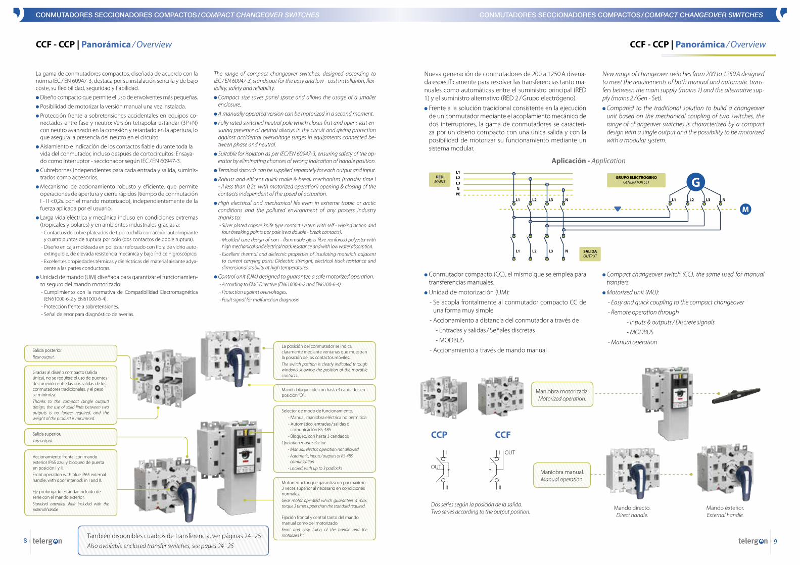
Disponibles desde 40 a 6300 A en versiones tripolar, tetrapo-lar, hexapolar y octopolar con las funciones de interruptor, conmutador y bypass.
Gracias a sus características constructivas estos interrupto-res pueden maniobrar eficazmente, sin riesgo para el usua-rio, en prácticamente cualquier situación.
Maniobra bajo carga hasta 1000 V en corriente alterna (in-ductivas y capacitivas) y corrienrte continua.
Intensidad de corte de hasta 8 veces la intensidad de empleo.
Capacidad de establecer y soportar intensidades de corto-circuito de hasta 100 kA.
Servicio ininterrumpido en condiciones extremas (tropica-les y polares) y en ambientes industriales.
Protección frente a sobretensiones accidentales en equipos co-nectados entre fase y neutro: Versión tetrapolar estándar (3P+N) con neutro avanzado en la conexión y retardado en la apertura.
Aislamiento e indicación de los contactos fiable durante toda la vida del interruptor incluso después de cortocir-cuitos: Ensayado como interruptor seccionador según IEC / EN 60947-3.
Available from 40 to 6300 A in three, four, six & eight poles to be used as on - off switches, changeover switches and bypass switches .
Thanks to their construction features, these switches can prac-tically handle any situation in electrical circuits without any risk for the operator .
On - Load switching of DC and AC (inductive an capacitive) loads up to 1000 V .
Rated breaking current of up to 8 times the rated operational current .
High making and withstanding currents: Up to 100 kA short circuit currents .
Uninterrupted duties in extreme tropic and artic conditions as well as the polluted environment of any industrial process .
Protection against accidental over voltages in equipments connect-ed between phase and neutral: Four pole standard version (3P+N) with advanced switched neutral pole (early make - late break) .
Reliable isolation and contact position indication throughout the life - time of the switch, even after short - circuits: tested as switch - disconnector according to IEC / EN 60947-3 .
Interruptor S5000 O - I / ON - OFF S5000 Switch
Serie / Series S5 S5M
Posiciones / Positions O - I O - I
Rango / Range 40... 6300 A 125 ... 1800 A
Polos / Poles 3 - 4 6 - 8
Accionamientos / Operations
mando directo / direct handle
mando panel / external handle IP65
Conexión / Connection
40... 160 A 125... 6300 A
Conmutador S5000L / Changeover switch S5000LSerie / Series S5L
Posiciones / Positions I - O - IIRango / Range 40... 160 APolos / Poles 3 - 4
Accionamientos / Operations
mando directo / direct handle
mando panel / external handle IP65
Conexión / Connection
Conmutador S5000F Changeover switch S5000FSerie / Series S5FPosiciones / Positions I - O - IIRango / Range 125 - 160 - 200; 1600... 3150 APolos / Poles 3 - 4
Accionamientos / Ope-rations
mando directo / direct handle
mando panel / external handle IP65
Conexión / Connection
Conmutador bypass S5000B Bypass changeover switch S5000BSerie / Series S5BPosiciones / Positions I - O - IIRango / Range 125... 1800 APolos / Poles 3 - 4
Accionamientos / Ope-rations
mando directo / direct handle
mando panel / external handle IP65
Conexión / Connection
Versiones motorizadas UM Motorized versions MUSerie / Series UM-S UM-C
Posiciones / Positions O - I I - O - IIRango / Range 250... 3150 A 200... 1800 APolos / Poles 3 - 4 3 - 4
Conexión / Connection
Interruptor S5000 DC O-I / ON-OFF S5000 Switch DCSerie / Series S5 DCPosiciones / Positions O - IRango / Range 80 - 1800 A
Polos / Poles 4
Accionamientos / Operations
mando directo / direct handle
mando panel / external handle IP65
Conexión / Connection 80 - 160 A
160 - 1800 A
Amplia gama de accesorios / Wide range of accessories
Los interruptores seccionadores S5000 se han diseñado de acuerdo con las especificaciones de la norma IEC/EN 60947-3 para su empleo en instalaciones civiles e industriales de baja tensión.
Diseño en caja moldeada en poliéster reforzado con fibra de vidrio autoextinguible, de elevada resistencia mecánica y bajo indice higroscópico.
Excelentes propiedades térmicas y dielectricas del material aislante adyacente a las partes conductoras: Alta rigidez dieléctrica, estabilidad dimensional a altas temperaturas y elevada resistencia a las corrientes de fuga superficiales.
Contactos de tipo cuchilla con acción autolimpiante en las superficies de contacto cuya disposición proporciona:
- Alto poder de cierre: El campo electromagnético creado por corrientes elevadas incrementa la presión de contacto.
- Contacto sin efecto rebote en entornos vibratorios
Cuatro puntos de ruptura por polo, con dos contactos de doble ruptura.
Contactos de doble etapa: La zona de trabajo de los contac-tos está libre del desgaste producido por el arco eléctrico; existe una sección adicional para soportarlo.
Mecanismo de accionamiento basado en un sistema de disparo libre por acumulación de energía en muelles, lo que permite operaciones de apertura y cierres bruscos, in-dependientemente de la velocidad aplicada por el usuario.
The switch - disconnectors S5000 has been designed according to standard IEC/EN 60947-3 for its use in low voltage civil and industrial installations .
Molded case design with frame parts of non - flammable glass fibre reinforced polyester with high mechanical and electrical track resistance and with low water absorption .
Excellent thermal and dielectric properties of insulating ma-terials adjacent to current - carrying parts: Dielectric strenght, electrical track resistance and dimensional stability at high temperatures .
Knife - type contacts with self - wiping action on the contact surfaces, providing:
- Under heavy starting currents or with short - circuit conditions, the contact pressure is increased .
- Shock and vibration proof contacts .
Four breaking points per pole with two double - break contacts .
Two stage make / break contacts: The working contact is free of the damaging effect of the electrical arc; an additional section is provided to take up that strain .
Quick make - break action with a spring loaded energy mecha-nism, which ensures independent operation .
Fijación para carril DIN (125 - 160 A ). (accesorio).
Mounting to DIN rail (125 - 160 A ) . (accessory) .
Conexión tipo pala (125 - 6300 A)Lug type connection (125 - 6300 A)
Contacto auxiliar de señalización y mando que en la maniobra de cierre (O - I) conmuta después de los contactos principales y en la de apertura (I - O) conmuta antes (accesorio). Ie = 16 A (cargas resistivas) / 4 A (cargas inductivas) a 250 Vac.Auxiliary contact for use as signal and control contact that switch after the main contacts whilst closing (O - I) and before whilst opening (I - O) (accessory) . Ie = 16 A (resistive loads) / 4 A (inductive loads) at 250 Vac .
Indicación clara de la posición de los contactos a través de una ventana que permite ver la situación del conjunto de contactos móviles.Clear contact position indication via a window in the switch housing, on the moving contact assembly .
Eje prolongado estándar incluido de serie con el mando exterior. Standard extended shaft included with the external handle .
Accionamiento frontal con mando exterior IP65 azul (estándar) o rojo / amarillo (emergencia), y bloqueo de puerta. Ver página 5.Front operation with blue (standard) or red / yellow (emergency) IP65 external handle, with door interlocking . See page 5 .
Mando bloqueable con hasta 3 candados en posición “O” (otras posiciones bajo demanda).Padlockable with up to three padlocks in “OFF” (other positions under request) .
Cubrebornes para interruptores de conexión tipo pala (accesorio).Terminal shrouds for lug type connection switches (accessory) .
Placa cubrebornes para interruptores de conexión tipo pala (accesorio).Terminal protection for lug type connection switches (accessory) .
Accionamiento frontal con mando directo. Front operation with direct handle .
98
CONMUTADORES SECCIONADORES COMPACTOS / COMPACT CHANGEOVER SWITCHES CONMUTADORES SECCIONADORES COMPACTOS / COMPACT CHANGEOVER SWITCHES
CCF - CCP | Panorámica / Overview CCF - CCP | Panorámica / Overview
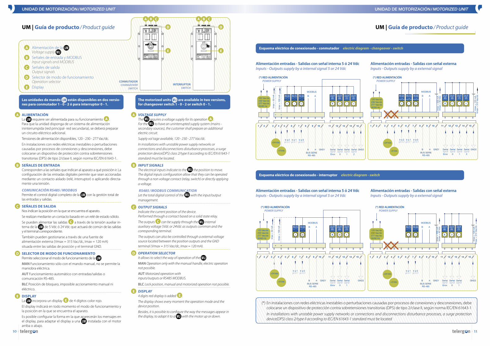
Nueva generación de conmutadores de 200 a 1250 A diseña-da específicamente para resolver las transferencias tanto ma-nuales como automáticas entre el suministro principal (RED 1) y el suministro alternativo (RED 2 / Grupo electrógeno).
Frente a la solución tradicional consistente en la ejecución de un conmutador mediante el acoplamiento mecánico de dos interruptores, la gama de conmutadores se caracteri-za por un diseño compacto con una única salida y con la posibilidad de motorizar su funcionamiento mediante un sistema modular.
New range of changeover switches from 200 to 1250 A designed to meet the requirements of both manual and automatic trans-fers between the main supply (mains 1) and the alternative sup-ply (mains 2 / Gen - Set) .
Compared to the traditional solution to build a changeover unit based on the mechanical coupling of two switches, the range of changeover switches is characterized by a compact design with a single output and the possibility to be motorized with a modular system .
CCP
Mando directo. Direct handle .
Mando exterior. External handle .
Dos series según la posición de la salida . Two series according to the output position .
OUT
I
II
OUTI
II
La gama de conmutadores compactos, diseñada de acuerdo con la norma IEC / EN 60947-3, destaca por su instalación sencilla y de bajo coste, su flexibilidad, seguridad y fiabilidad.
Diseño compacto que permite el uso de envolventes más pequeñas.
Posibilidad de motorizar la versión manual una vez instalada.
Protección frente a sobretensiones accidentales en equipos co-nectados entre fase y neutro: Versión tetrapolar estándar (3P+N) con neutro avanzado en la conexión y retardado en la apertura, lo que asegura la presencia del neutro en el circuito.
Aislamiento e indicación de los contactos fiable durante toda la vida del conmutador, incluso después de cortocircuitos: Ensaya-do como interruptor - seccionador según IEC / EN 60947-3.
Cubrebornes independientes para cada entrada y salida, suminis-trados como accesorios.
Mecanismo de accionamiento robusto y eficiente, que permite operaciones de apertura y cierre rápidos (tiempo de conmutación I - II <0,2s. con el mando motorizado), independientemente de la fuerza aplicada por el usuario.
Larga vida eléctrica y mecánica incluso en condiciones extremas (tropicales y polares) y en ambientes industriales gracias a:
- Contactos de cobre plateados de tipo cuchilla con acción autolimpiante y cuatro puntos de ruptura por polo (dos contactos de doble ruptura).
- Diseño en caja moldeada en poliéster reforzado con fibra de vidrio auto-extinguible, de elevada resistencia mecánica y bajo índice higroscópico.
- Excelentes propiedades térmicas y dieléctricas del material aislante adya-cente a las partes conductoras.
Unidad de mando (UM) diseñada para garantizar el funcionamien-to seguro del mando motorizado.
- Cumplimiento con la normativa de Compatibilidad Electromagnética (EN61000-6-2 y EN61000-6-4).
- Protección frente a sobretensiones. - Señal de error para diagnóstico de averias.
The range of compact changeover switches, designed according to IEC / EN 60947-3, stands out for the easy and low - cost installation, flex-ibility, safety and reliability .
Compact size saves panel space and allows the usage of a smaller enclosure .
A manually operated version can be motorized in a second moment .
Fully rated switched neutral pole which closes first and opens last en-suring presence of neutral always in the circuit and giving protection against accidental overvoltage surges in equipments connected be-tween phase and neutral .
Suitable for isolaton as per IEC/EN 60947-3, ensuring safety of the op-erator by eliminating chances of wrong indication of handle position .
Terminal shrouds can be supplied separately for each output and input .
Robust and efficent quick make & break mechanism (transfer time I - II less than 0,2s . with motorized operation) opening & closing of the contacts independent of the speed of actuation .
High electrical and mechanical life even in extreme tropic or arctic conditions and the polluted environment of any process industry thanks to:
- Silver plated copper knife type contact system with self - wiping action and four breaking points por pole (two double - break contacts) .
- Moulded case design of non - flammable glass fibre reinforced polyester with high mechanical and electrical track resistance and with low water absorption .
- Excellent thermal and dielectric properties of insulating materials adjacent to current carrying parts: Dielectric strenght, electrical track resistance and dimensional stability at high temperatures .
Control unit (UM) designed to guarantee a safe motorized operation . - According to EMC Directive (EN61000-6-2 and EN6100-6-4) . - Protection against overvoltages . - Fault signal for malfunction diagnosis .
Salida superior.Top output .
La posición del conmutador se indica claramente mediante ventanas que muestran la posición de los contactos móviles.The switch position is clearly indicated through windows showing the position of the movable contacts .
Mando bloqueable con hasta 3 candados en posición “O” .
Selector de modo de funcionamiento. - Manual, maniobra eléctrica no permitida - Automático, entradas / salidas o
comunicación RS-485 - Bloqueo, con hasta 3 candados Operation mode selector . - Manual, electric operation not allowed - Automatic, inputs / outputs or RS-485
comunication - Locked, with up to 3 padlocks
Conmutador compacto (CC), el mismo que se emplea para transferencias manuales.
Unidad de motorización (UM):
- Se acopla frontalmente al conmutador compacto CC de una forma muy simple
- Accionamiento a distancia del conmutador a través de
- Entradas y salidas / Señales discretas
- MODBUS
- Accionamiento a través de mando manual
Compact changeover switch (CC), the same used for manual transfers .
Motorized unit (MU):
- Easy and quick coupling to the compact changeover
- Remote operation through
- Inputs & outputs / Discrete signals
- MODBUS
- Manual operation
Gracias al diseño compacto (salida única), no se requiere el uso de puentes de conexión entre las dos salidas de los conmutadores tradicionales, y el peso se minimiza.Thanks to the compact (single output) design, the use of solid links between two outputs is no longer required, and the weight of the product is minimised .
Salida posterior.Rear output .
CCF
REDMAINS
GRUPO ELECTRÓGENOGENERATOR SET
SALIDAOUTPUT
Aplicación - Application
Motorreductor que garantiza un par máximo 3 veces superior al necesario en condiciones normales.Gear motor operated which guarantees a max . torque 3 times upper than the standard required .
Fijación frontal y central tanto del mando manual como del motorizado.Front and easy fixing of the handle and the motorized kit .
Accionamiento frontal con mando exterior IP65 azul y bloqueo de puerta en posición I y II.Front operation with blue IP65 external handle, with door interlock in I and II.
Eje prolongado estándar incluido de serie con el mando exterior. Standard extended shaft included with the external handle .
Maniobra motorizada.Motorized operation .
Maniobra manual.Manual operation .
También disponibles cuadros de transferencia, ver páginas 24 - 25
Also available enclosed transfer switches, see pages 24 - 25
1110
UNIDAD DE MOTORIZACIÓN / MOTORIZED UNIT
UM | Guía de producto / Product guide UM | Guía de producto / Product guide
UNIDAD DE MOTORIZACIÓN / MOTORIZED UNIT
A Alimentación de la Voltage supply
B Señales de entrada y MODBUS Input signals and MODBUS
C Señales de salida Output signals
D Selector de modo de funcionamiento Operation selector
E Display
A B C
D
EUM-S31230Z
Las unidades de mando están disponibles en dos versio-nes para conmutador 1 - 0 - 2 ó para interruptor 0 - 1.
A ALIMENTACIÓNLa requiere ser alimentada para su funcionamiento A . Para que la unidad disponga de un sistema de alimentación ininterrumpida (red principal- red secundaria), se deberá preparar un circuito eléctrico adicional.
Tensiones de alimentación disponibles, 120 - 230 - 277 Vac/dc.
En instalaciones con redes eléctricas inestables o perturbaciones causadas por procesos de conexiones y desconexiones, debe colocarse un dispositivo de protección contra sobretensiones transitorias (DPS) de tipo 2/clase II, según norma IEC/EN 61643-1.
B SEÑALES DE ENTRADACorresponden a las señales que indican al aparato a qué posición ir. La configuración de las entradas digitales permite que sean accionadas mediante un contacto aislado (relé, interruptor) o aplicando directa-mente una tensión.
COMUNICACIÓN RS485 / MODBUSPermite el control digital completo de la con la gestión total de las entradas y salidas.
C SEÑALES DE SALIDANos indican la posición en la que se encuentra el aparato.
Se realizan mediante un contacto basado en un relé de estado sólido.
Se pueden alimentar las salidas C a través de la tensión auxiliar in-terna de la de 5 Vdc ó 24 Vdc que actuará de común de las salidas y el terminal correspondiente.
También pueden gestionarse a través de una fuente de alimentación externa (Vmax = 315 Vac/dc, Imax = 120 mA) situada entre las salidas de posición y el terminal GND.
D SELECTOR DE MODO DE FUNCIONAMIENTOPermite seleccionar el modo de funcionamiento de la
MAN Funcionamiento sólo con el mando manual, no se permite la maniobra eléctrica.
AUT Funcionamiento automático con entradas/salidas o comunicación RS-485.
BLC Posición de bloqueo, imposible accionamiento manual ni eléctrico.
E DISPLAYLa incorpora un display E de 4 dígitos color rojo.
El display indicará en todo momento el modo de funcionamiento y la posición en la que se encuentra el aparato.
Es posible configurar la forma en la que aparecerán los mensajes en el display, para adaptar el display a una instalada con el motor arriba o abajo.
The motorized units are available in two versions, for changeover switch 1 - 0 - 2 or switch 0 - 1.
A VOLTAGE SUPPLYThe requires a voltage supply for its operation A . For the to have an uninterrupted supply system (mains - secondary sources), the customer shall prepare an additional electric circuit .
Supply vol tage available, 120 - 230 - 277 Vac/dc .
In installations with unstable power supply networks or connections and disconnections disturbance processes, a surge protection device(DPS) class 2/type II according to IEC/EN 61643-1 standard must be located .
B INPUT SIGNALSThe electrical inputs indicate to the the position to move .The digital inputs configuration allow that they can be operated through a non voltage contact (relay, switch) or directly applying a voltage .
RS485 / MODBUS COMMUNICATIONLet the total digital control of the with the input/output management .
C OUTPUT SIGNALSIndicate the current position of the device .Performed through a contact based on a solid state relay .
The outputs C can be supply through the internal auxiliary voltage 5Vdc or 24Vdc as outputs common and the corresponding terminal .
The outputs can also be controlled through a external voltage source located between the position outputs and the GND terminal (Vmax = 315 Vac/dc, Imax = 120 mA) .
D OPERATION SELECTORIt allows to select the way of operation of the
MAN Operation only with the manual handle, electric operation not possible .
AUT Motorized operation with inputs/outputs or RS485 MODBUS .
BLC Lock position, manual and motorized operation not possible .
E DISPLAY4 digits red display is added E .
The display shows every moment the operation mode and the device position .
Besides, it is possible to configure the way the messages appear in the display, to adapt it to a with the motor up or down .
Alimentación entradas - Salidas con señal interna 5 ó 24 Vdc Inputs - Outputs supply by a internal signal 5 or 24 Vdc
Alimentación entradas - Salidas con señal interna 5 ó 24 Vdc Inputs - Outputs supply by a internal signal 5 or 24 Vdc
Alimentación entradas - Salidas con señal externa Inputs - Outputs supply by a external signal
Alimentación entradas - Salidas con señal externa Inputs - Outputs supply by a external signal
OUT (E)
IN (1) OUT (0)
IN (0) OUT (1)
B A
MODBUS
B A GND1BUS SERIE
RS-485
E
4 9 1410 153 8 131 2 5 6 117 12
+24 Vdc
+5 Vdc GND2Señal signal Error
Señal signal
0
Señal signal
1
Ir a 1 go to 1
Ir a 0 go to 0
(*) RED ALIMENTACIÓN POWER SUPPLY
120 Vac/dc 230 Vac/dc 277 Vac/dc 50/60 Hz Im
ax =
50
mA
Imax
= 1
00 m
A
(*) RED ALIMENTACIÓN POWER SUPPLY
IN (2) OUT (E)
OUT (2)
IN (1) OUT (0)
IN (0) OUT (1)
B A
Imax
= 5
00 m
A
Imax
= 1
20 m
A
Vm
ax =
40
Vdc
Vm
ax =
315
Vac
/dc
MODBUS
B A GND1 GND2BUS SERIE
RS-485
E
4 9 1410 153 8 131 2 5 6 117 12
+24 Vdc
+5 VdcSeñal signal Error
Señal signal
0
Señal signal
1
Señal signal
2
Ir a 2 go to 2
Ir a 1 go to 1
Ir a 0 go to 0
120 Vac/dc 230 Vac/dc 277 Vac/dc 50/60 Hz
(*) RED ALIMENTACIÓN POWER SUPPLY
OUT (E)
IN (1) OUT (0)
IN (0) OUT (1)
B A
MODBUS
B A GND1 GND2BUS SERIE
RS-485
E
4 9 1410 153 8 131 2 5 6 117 12
+24 Vdc
+5 VdcSeñal signal Error
Señal signal
0
Señal signal
1
Ir a 1 go to 1
Ir a 0 go to 0
Imax
= 5
00 m
AV
max
= 4
0 V
dc
Imax
= 1
20 m
AV
max
= 3
15 V
ac/d
c
120 Vac/dc 230 Vac/dc 277 Vac/dc 50/60 Hz
A B C
D
E
INTERRUPTORSWITCH
CONMUTADORCHANGEOVER
SWITCH
Esquema eléctrico de conexionado - conmutador electric diagram - changeover - switch
Esquema eléctrico de conexionado - interruptor electric diagram - switch
IN (2) OUT (E)
OUT (2)
IN (1) OUT (0)
IN (0) OUT (1)
B A
MODBUS
Imax
= 5
0 m
A
Imax
= 1
00 m
A
B A GND1BUS SERIE
RS-485
E
4 9 1410 153 8 131 2 5 6 117 12
+24 Vdc
+5 Vdc
(*) RED ALIMENTACIÓN POWER SUPPLY
120 Vac/dc 230 Vac/dc 277 Vac/dc 50/60 Hz
GND2Señal signal Error
Señal signal
0
Señal signal
1
Señal signal
2
Ir a 2 go to 2
Ir a 1 go to 1
Ir a 0 go to 0
(*) En instalaciones con redes eléctricas inestables o perturbaciones causadas por procesos de conexiones y desconexiones, debe colocarse un dispositivo de protección contra sobretensiones transitorias (DPS) de tipo 2/clase II, según norma IEC/EN 61643-1
In installations with unstable power supply networks or connections and disconnections disturbance processes, a surge protection device(DPS) class 2/type II according to IEC/EN 61643-1 standard must be located


