
Pneumatic Control Box Manual 1
Pneumatic
Control Box
Manual
I630-E-01
Pneumatic Control Box Manual 2
This Manual contains information of the Techman Robot product series (hereinafter referred to as the TM
Robot).The information contained herein is the property of Omron Corporation (hereinafter referred to as the
Corporation) and Techman Robot Inc. No part of this publication may be reproduced or copied in any way,
shape or form without prior authorization from the Corporation. No information contained herein shall be
considered an offer or commitment. It may be subject to change without notice. This Manual will be reviewed
periodically. The Corporation will not be liable for any error or omission.
logo is the registered trademark of TECHMAN ROBOT INC. and the company reserves the
ownership of this manual and its copy and its copyrights.
Pneumatic Control Box Manual 3
Contents
Revision History Table .................................................................................................................................. 4
1. TM Hardware Kit ................................................................................................................................... 5
2. Installation ............................................................................................................................................. 6
3. Pressure Sensor Setting ...................................................................................................................... 12
4. KILEWS Accessories ........................................................................................................................... 14
Appendix A TM Robot Control Box HW 3.0 Wires Assignment .................................................................... 15
Appendix B Terminal Block Description ...................................................................................................... 16
Pneumatic Control Box Manual 4
Revision History Table
Revision Date Revised Content
01 October, 2018 Original Release
Pneumatic Control Box Manual 5
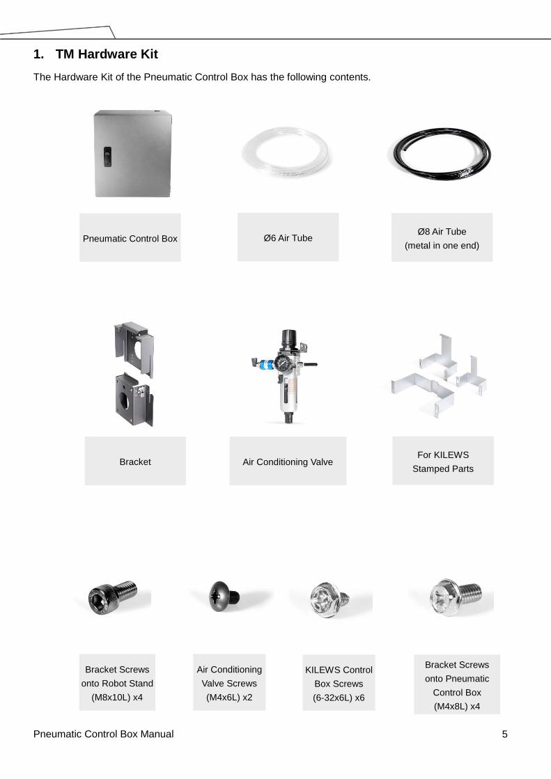
1. TM Hardware Kit
The Hardware Kit of the Pneumatic Control Box has the following contents.
Pneumatic Control Box
Bracket Screws
onto Robot Stand
(M8x10L) x4
Ø6 Air Tube Ø8 Air Tube
(metal in one end)
Bracket For KILEWS
Stamped Parts Air Conditioning Valve
Air Conditioning
Valve Screws
(M4x6L) x2
KILEWS Control
Box Screws
(6-32x6L) x6
Bracket Screws
onto Pneumatic
Control Box
(M4x8L) x4

Pneumatic Control Box Manual 6
2. Installation
Step 1 Pneumatic Control Box with Robot Stand
It is recommended to attach the TM Pneumatic Control Box on to the TM Robot Stand. The user can
also skip this step if there is no robot stand.
Screw the bracket onto Pneumatic control box (back)
Screw another bracket onto Robot Stand
Sliding for installation
4pcs-M4-8
4pcs-M8-10
Pneumatic Control Box Manual 7
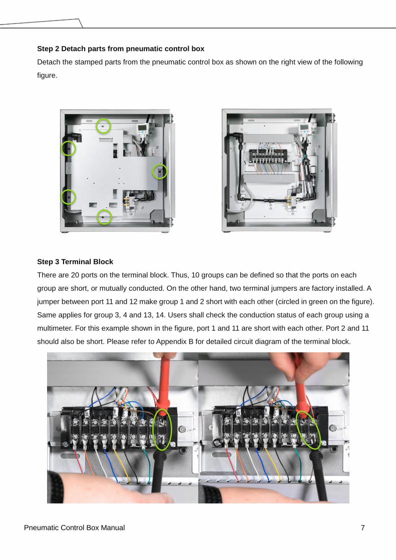
Step 2 Detach parts from pneumatic control box
Detach the stamped parts from the pneumatic control box as shown on the right view of the following
figure.
Step 3 Terminal Block
There are 20 ports on the terminal block. Thus, 10 groups can be defined so that the ports on each
group are short, or mutually conducted. On the other hand, two terminal jumpers are factory installed. A
jumper between port 11 and 12 make group 1 and 2 short with each other (circled in green on the figure).
Same applies for group 3, 4 and 13, 14. Users shall check the conduction status of each group using a
multimeter. For this example shown in the figure, port 1 and 11 are short with each other. Port 2 and 11
should also be short. Please refer to Appendix B for detailed circuit diagram of the terminal block.
Pneumatic Control Box Manual 8
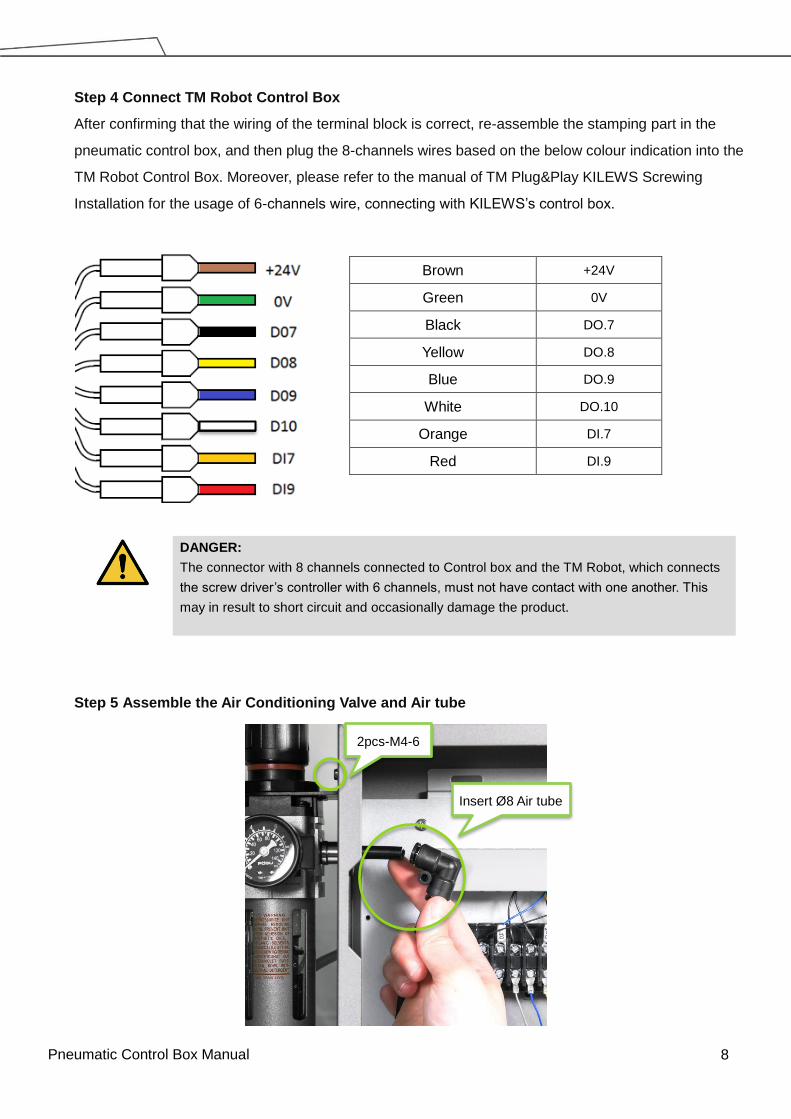
Step 4 Connect TM Robot Control Box
After confirming that the wiring of the terminal block is correct, re-assemble the stamping part in the
pneumatic control box, and then plug the 8-channels wires based on the below colour indication into the
TM Robot Control Box. Moreover, please refer to the manual of TM Plug&Play KILEWS Screwing
Installation for the usage of 6-channels wire, connecting with KILEWS’s control box.
DANGER:
The connector with 8 channels connected to Control box and the TM Robot, which connects
the screw driver’s controller with 6 channels, must not have contact with one another. This
may in result to short circuit and occasionally damage the product.
Step 5 Assemble the Air Conditioning Valve and Air tube
Brown +24V
Green 0V
Black DO.7
Yellow DO.8
Blue DO.9
White DO.10
Orange DI.7
Red DI.9
2pcs-M4-6
Insert Ø8 Air tube
Pneumatic Control Box Manual 9
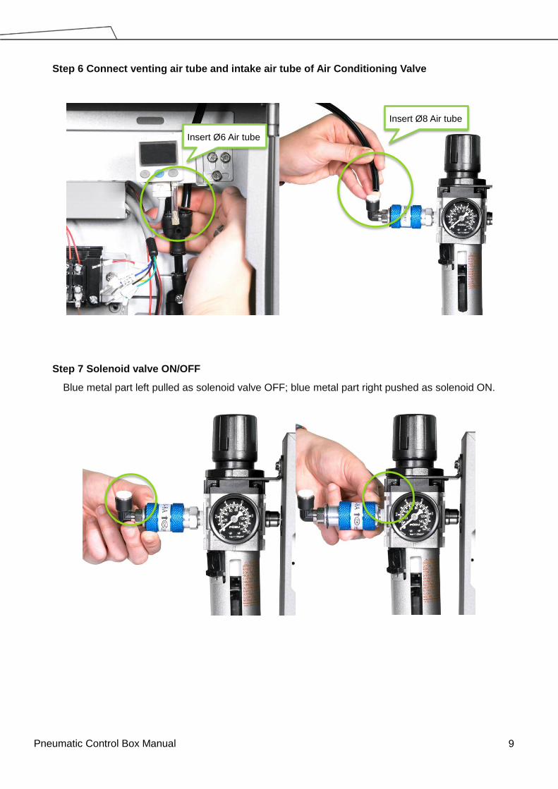
Step 6 Connect venting air tube and intake air tube of Air Conditioning Valve
Step 7 Solenoid valve ON/OFF
Blue metal part left pulled as solenoid valve OFF; blue metal part right pushed as solenoid ON.
Insert Ø6 Air tube
Insert Ø8 Air tube
Pneumatic Control Box Manual 10
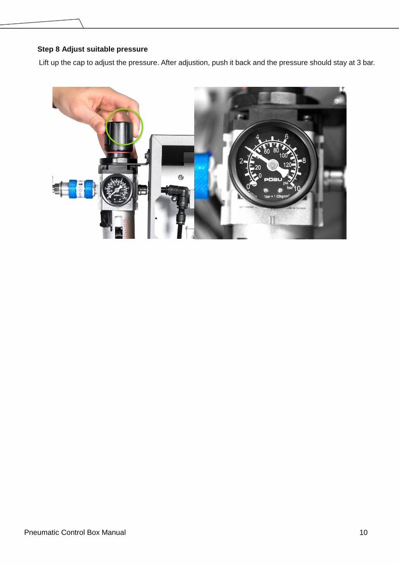
Step 8 Adjust suitable pressure
Lift up the cap to adjust the pressure. After adjustion, push it back and the pressure should stay at 3 bar.

Pneumatic Control Box Manual 11
Step 9 Testing pressure
Give orders through IO command by using TM Robot HMI and examine whether or not it fulfils the below
condition when vacuuming:
Suction-9 ~ -11kPa; blowing >80kPa
DO.7 Screw driver rotate
DO.8 Counter-rotate
DO.9 Suck
DO.10 Blow
If you cannot reach the above values, confirm whether or not there’s leaking or regulating valve pressure
is less than 3bar.
For detailed user manual of the sensor, download it from CKD’s official website as below:
(http://www.ckdtaiwan.com.tw/catafile/pdf/CC-1345T.pdf)
Pneumatic Control Box Manual 12
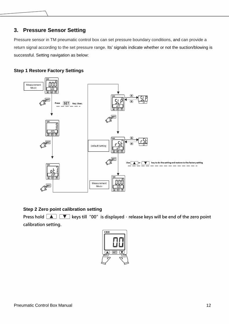
3. Pressure Sensor Setting
Pressure sensor in TM pneumatic control box can set pressure boundary conditions, and can provide a
return signal according to the set pressure range. Its’ signals indicate whether or not the suction/blowing is
successful. Setting navigation as below:
Step 1 Restore Factory Settings
Step 2 Zero point calibration setting
Press hold keys till“00”is displayed,release keys will be end of the zero point
calibration setting.

Pneumatic Control Box Manual 13
Step 3 Set OUT1 function setting mode as comparator setting mode
Step 4 Set the Max. / Min. value of pressure
Set H-1as -11 Kpa,L-1as -9Kpa,between the range of -9~-1, the pressure sensor will give output signal.
Users can base on the signal and know whether or not the suction/blowing is successful.
Pneumatic Control Box Manual 14
4. KILEWS Accessories
The accessories that TM pneumatic control box (TM Hardware Kit) provides, such as KILEWS stamping
parts and KILEWS control box, are compatible with KILEWS Screw Driver Model BN512L. For detailed
information refer to the manual TM Plug & Play KILEWS Screwing Installation.

Pneumatic Control Box Manual 15
Appendix A TM Robot Control Box HW 3.0 Wires Assignment
TM Control Box Digital IN wires assignment
TM Control Box Digital OUT wires assignment

Pneumatic Control Box Manual 16
Appendix B Terminal Block Description
Upper Right to Left ○1 ~○10,Bottom Right to Left ○11 ~○20。
Terminal block Device Equipment Remarks
○1 Solenoid valve A (Red) +24V(with cooper pieces)
○2 Solenoid Valve B(Red)
Sensor (Brown)
○3 Sensor (Blue)
Kilews IO BOX Pin5 (Red)
0V(with copper pieces)
○4 Kilews IO BOX Pin2 Start IN GND (Yellow)
Kilews IO BOX Pin4 Rev IN GND (Blue)
○5 Kilews IO BOX Pin1(White) Screwdriver Turns
○6 Kilews IO BOX Pin3(Green) Reverse mode
○7 Solenoid Valve B (Black) Suction
○8 Solenoid Valve A (Black) Blow
○9 Kilews IO BOX Pin7 (Black)
○10 Sensor (Black)
○11 Robot Control Box (Brown) +24V
○12
○13 Robot Control Box (Green) 0V
○14
○15 Robot Control Box DO.7 (Black)
○16 Robot Control Box DO.8 (Yellow)
○17 Robot Control Box DO.9 (Blue)
○18 Robot Control Box DO.10 (White)
○19 Robot Control Box DI.7 (Orange)
○20 Robot Control Box DI.9 (Red)

17
Cat. No I630-E-01 1018 (1018)
19888-930 A


