
Plane Kinematics of Rigid BodiesRigid Body• A system of particles for which the distances between the particles remain
unchanged.
• This is an ideal case. There is always some deformation in materials under the
action of loads. This deformation can be neglected if the changes in the shape
are small compared to the movement of the body as a whole.
Particle Kinematics • Developed the relationships governing the disp, vel, and accln of points as they
move along straight or curved paths.
Rigid Body Kinematics• Same relationships will be used. In addition, rotational motion of rigid bodies will
also be accounted for.
• Involves both linear and angular disp, vel, and accln.
• Discussion will be restricted to motion in a Single Plane (Plane Motion).
When all parts of the body move in parallel planes
Plane containing mass center is generally considered as plane of motion
and the body is treated as a thin slab whose motion is confined to the
plane of the slab.1ME101 - Division III Kaustubh Dasgupta
Plane Kinematics of Rigid Bodies
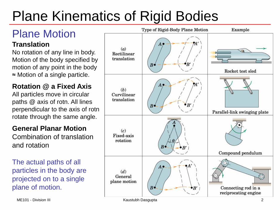
Plane MotionTranslationNo rotation of any line in body.
Motion of the body specified by
motion of any point in the body
≈ Motion of a single particle.
Rotation @ a Fixed AxisAll particles move in circular
paths @ axis of rotn. All lines
perpendicular to the axis of rotn
rotate through the same angle.
General Planar Motion
Combination of translation
and rotation
The actual paths of all
particles in the body are
projected on to a single
plane of motion.
2ME101 - Division III Kaustubh Dasgupta
Plane Kinematics of Rigid Bodies
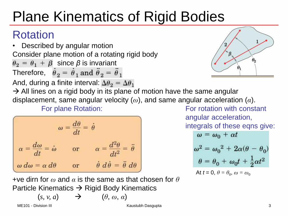
Rotation• Described by angular motion
Consider plane motion of a rotating rigid body
since β is invariant
Therefore,
And, during a finite interval:
All lines on a rigid body in its plane of motion have the same angular
displacement, same angular velocity (ω), and same angular acceleration (α).
For plane Rotation: For rotation with constant
angular acceleration,
integrals of these eqns give:
+ve dirn for ω and α is the same as that chosen for θ
Particle Kinematics Rigid Body Kinematics
(s, v, a) (θ, ω, α)
At t = 0, θ = θ0, ω = ω0
3ME101 - Division III Kaustubh Dasgupta

Plane Kinematics of Rigid Bodies
Rotation @ a Fixed Axis•All points (except those on the axis) move
in concentric circles @ the fixed axis normal
to the plane of the figure
Vel of A using n-t for circular motion:
For particle circular motion For body rotational motion
rrvvrv tn ,0
4ME101 - Division III Kaustubh Dasgupta

Plane Kinematics of Rigid Bodies
• Rotation @ a Fixed Axis
5ME101 - Division III Kaustubh Dasgupta
Using the cross-product relationship of
vector notation:
The vector equivalent eqns:

Plane Kinematics of Rigid Bodies
Absolute Motion Analysis
•First approach to rigid body kinematics
•Similar to the absolute motion analysis of the constrained motion of
connected particles discussed in kinematics of particles (for pulley
configurations considered, the relevant velocities and accelerations were
obtained by successive differentiation of the lengths of the connecting
cables).
•In case of absolute motion analysis of rigid bodies, both linear and
angular velocities and linear and angular accelerations are required to be
considered.
6ME101 - Division III Kaustubh Dasgupta
Plane Kinematics of Rigid Bodies
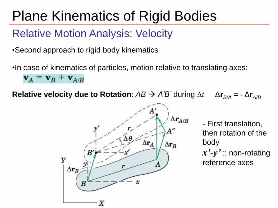
Relative Motion Analysis: Velocity
•Second approach to rigid body kinematics
•In case of kinematics of particles, motion relative to translating axes:
Relative velocity due to Rotation: AB A’B’ during Δt ΔrB/A = - ΔrA/B
7ME101 - Division III Kaustubh Dasgupta
- First translation,
then rotation of the
body
x’-y’ :: non-rotating
reference axes

Plane Kinematics of Rigid Bodies
• Relative Motion Analysis: Velocity
8ME101 - Division III Kaustubh Dasgupta
To the non-rotating observer attached to B,
:: the body appears to undergo fixed axis rotation @ B
:: Point A executes circular motion
:: Equations developed for circular motions can be used

Plane Kinematics of Rigid Bodies
Relative Motion Analysis: VelocityRelative velocity due to Rotation
ΔrA/B = has the magnitude rΔθ as Δθ approaches zero
•ΔrA/B is accompanied by Δθ as seen from
translating axes x’-y’
Relative velocity Equation
Magnitude of the relative vel:
Using r to represent vector rA/B, relative velocity may be written as the vector:
From already derived vector eqn for velocity
ω is the angular velocity vector normal to the plane of the motion
Relative linear velocity is always perpendicular
to the line joining two points in question (A-B or
A’-B)9ME101 - Division III Kaustubh Dasgupta

Plane Kinematics of Rigid Bodies
Relative Motion Analysis: VelocityRelative velocity due to Rotation
• Visualizing the separate translation and rotation components
of the relative velocity equation
• Choosing B as the reference point
• Relative linear velocity is always perpendicular to the line joining two points in
question (A-B)
• ω is the absolute angular velocity of AB.
10ME101 - Division III Kaustubh Dasgupta

Plane Kinematics of Rigid Bodies
Relative Motion Analysis: VelocityExample
Solution: Choosing center O as the reference
point for relative velocity eqn since its
motion is given.
The relative velocity of A wrt O is observed
from the translating axes x-y attached to O.
11ME101 - Division III Kaustubh Dasgupta

Plane Kinematics of Rigid Bodies
Relative Motion Analysis: VelocityExample
Solution:
Direction of relative velocity is perpendicular to OA.
The angular velocity of OA is the same as that of the
wheel:
The vector sum vA can be calculated from law of
cosines:
Dirn of vA can be easily found out.
Point C momentarily has zero velocity and may also
be chosen as a reference point:
The problem may also be solved using vector formulation.
AC = 200sin30 + [(200cos30)2+(300)2]
= 436 mm
12ME101 - Division III Kaustubh Dasgupta

Plane Kinematics of Rigid Bodies
Instantaneous Center of Zero Velocity
•Relative Motion Analysis: velocity of a point on a rigid body in plane
motion = relative velocity due to rotation @ a convenient reference point
+ velocity of the reference point.
•The problem can also be solved by choosing a unique reference point
that momentarily has zero velocity.
This point lies on Instantaneous Axis of Zero Velocity (or
instantaneous axis of rotation), and intersection of this axis with the
plane of motion is known as Instantaneous Center of Zero
Velocity.
As far as velocities are concerned, the body may be considered to be
in pure rotation in a circular path @ the Instantaneous Axis of Zero
Velocity.
Locating the instantaneous center of zero velocity is important to
simplify the solution of many problems involving rigid body rotations
13ME101 - Division III Kaustubh Dasgupta

Plane Kinematics of Rigid Bodies
Instantaneous Center of Zero VelocityLocating the Instantaneous Center
• Assume that the dirns of absolute vel of any points A and B
on rigid body are known and are not parallel.
• If C is a point @ which A has absolute circular motion at the
instant considered, C must lie on the normal to vA through A.
• Similarly, point B can also have absolute circular motion @
C at the instant considered.
Intersection of two perpendiculars will give the absolute center of rotation at the
instant considered.
Point C is the instantaneous center of zero velocity and may lie on or off the body
Instantaneous center of zero velocity need not be a fixed point in the body or a
fixed point in the plane.
If vel of two points are parallel and the line joining the
points is perpendicular to the dirn of vel, the
instantaneous center is located by direct proportion.
As the parallel velocities become equal in magnitude, the IC
moves farther away from the body and approaches infinity in the
limit body stops rotating and translates only.
14ME101 - Division III Kaustubh Dasgupta

Plane Kinematics of Rigid Bodies
Instantaneous Center of Zero VelocityLocating the Instantaneous Center
If magnitude of velocity at one of the points on the rigid body
under general plane motion is known (vA)
Angular velocity of the body ω and linear velocity of every
point in the body can be easily obtained using:
ω = vA / rA this is also the angular velocity of every line in the body
velocity of B is vB = rBω = (rB / rA) vA
• Once the IC is located, the dirn of the
instantaneous velocity of every point in the
body is readily found since it must be
perpendicular to the radial line joining the
point in question with IC.
Velocity of all such points: v = rω
Note that the spokes are somewhat visible near IC,
whereas at the top of the wheel they become blurred.
Also note how the direction of velocity varies at different
point on the rim of the wheel.
15ME101 - Division III Kaustubh Dasgupta

Plane Kinematics of Rigid Bodies
Relative Motion Analysis: Velocity
Instantaneous Center of Zero Velocity
Motion of the Instantaneous Center
• IC changes its position in space and on the body as body changes its position
• Locus of the ICs in space is known as space centrode
• Locus of the ICs on the body is known as body centrode
• At the instant considered, the two curves are tangent at C
• The body centrode rolls on the space centrode during
the motion of the body.
• Although the IC of zero velocity is momentarily at rest,
its accln is generally not zero.
IC cannot be used as an IC of zero acceleration.
• Instantaneous center of zero acceleration exist for bodies in general plane
motion will not be discussed in ME101
16ME101 - Division III Kaustubh Dasgupta

Plane Kinematics of Rigid Bodies
Relative Motion Analysis: VelocityInstantaneous Center of Zero VelocityExample
17ME101 - Division III Kaustubh Dasgupta
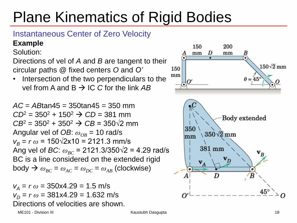
Plane Kinematics of Rigid BodiesInstantaneous Center of Zero VelocityExample
Solution:
Directions of vel of A and B are tangent to their
circular paths @ fixed centers O and O’
• Intersection of the two perpendiculars to the
vel from A and B IC C for the link AB
AC = ABtan45 = 350tan45 = 350 mm
CD2 = 3502 + 1502 CD = 381 mm
CB2 = 3502 + 3502 CB = 350√2 mm
Angular vel of OB: ωOB = 10 rad/s
vB = r ω = 150√2x10 = 2121.3 mm/s
Ang vel of BC: ωBC = 2121.3/350√2 = 4.29 rad/s
BC is a line considered on the extended rigid
body ωBC = ωAC = ωDC = ωAB (clockwise)
vA = r ω = 350x4.29 = 1.5 m/s
vD = r ω = 381x4.29 = 1.632 m/s
Directions of velocities are shown.18ME101 - Division III Kaustubh Dasgupta

Plane Kinematics of Rigid BodiesInstantaneous Center of Zero Velocity
Example
Show the instantaneous center of
zero velocity for member BC.
Solution:
Point B follow circular path of motion
because link AB is subjected to
rotation about a fixed axis.
vB is perpendicular to AB
Motion of B causes the piston to move
horizontally.
vC is horizontal
Draw lines perpendicular to vB and vC
These lines intersect at IC.
19ME101 - Division III Kaustubh Dasgupta

Plane Kinematics of Rigid BodiesInstantaneous Center of Zero Velocity
Example
Show the instantaneous center of
zero velocity for the link CB.
Solution:
Points B and C follow circular path of motion
because links AB and DC are subjected to rotation
about a fixed axis.
vB and vC are perpendicular to AB and DC at the
instant considered
Radial lines drawn perpendicular to vB and vC are
parallel and Intersect at infinity
ωCB = vC /∞ = o
Link CB momentarily translates
An instant later, CB will move to a tilted position,
causing IC to move to some finite location.
20ME101 - Division III Kaustubh Dasgupta
Plane Kinematics of Rigid BodiesInstantaneous Center of Zero Velocity
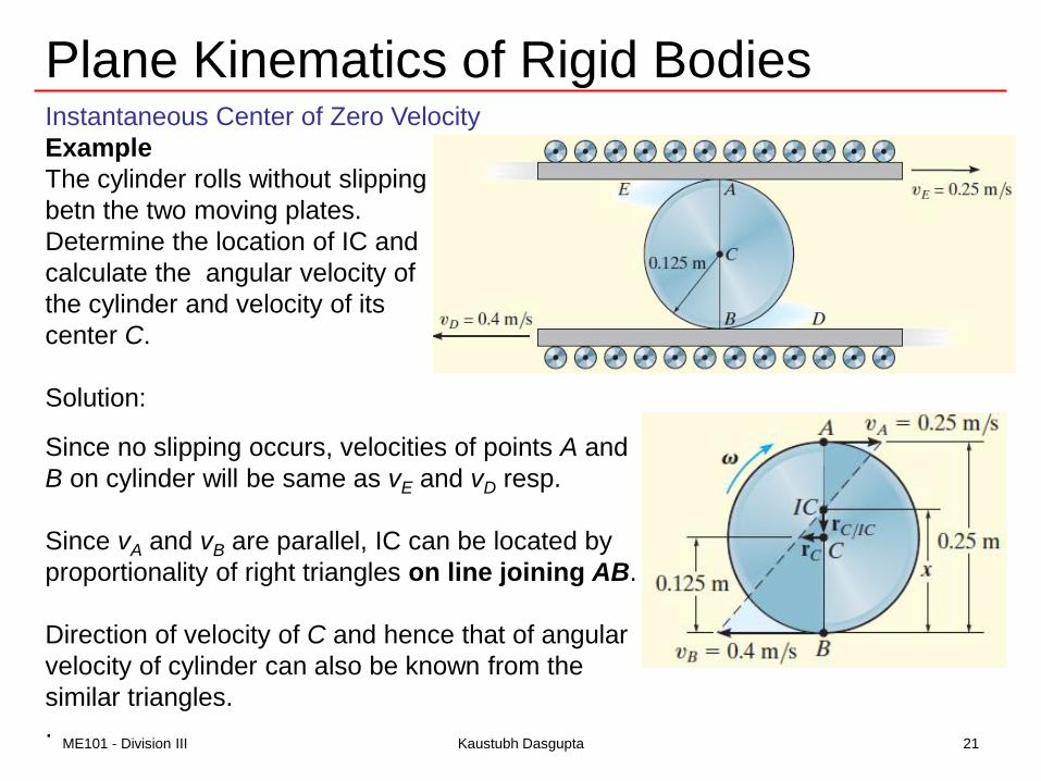
Example
The cylinder rolls without slipping
betn the two moving plates.
Determine the location of IC and
calculate the angular velocity of
the cylinder and velocity of its
center C.
Solution:
Since no slipping occurs, velocities of points A and
B on cylinder will be same as vE and vD resp.
Since vA and vB are parallel, IC can be located by
proportionality of right triangles on line joining AB.
Direction of velocity of C and hence that of angular
velocity of cylinder can also be known from the
similar triangles.
.21ME101 - Division III Kaustubh Dasgupta
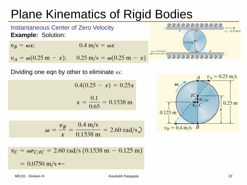
Plane Kinematics of Rigid BodiesInstantaneous Center of Zero Velocity
Example: Solution:
Dividing one eqn by other to eliminate ω:
22ME101 - Division III Kaustubh Dasgupta
Plane Kinematics of Rigid Bodies
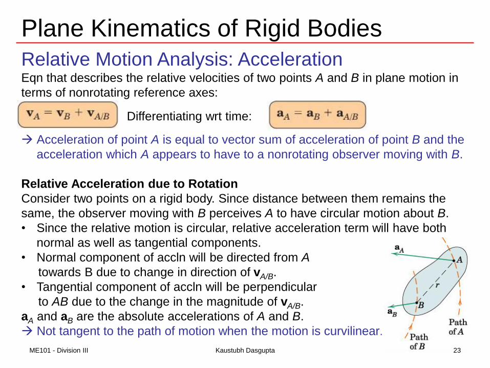
Relative Motion Analysis: AccelerationEqn that describes the relative velocities of two points A and B in plane motion in
terms of nonrotating reference axes:
Differentiating wrt time:
Acceleration of point A is equal to vector sum of acceleration of point B and the
acceleration which A appears to have to a nonrotating observer moving with B.
Relative Acceleration due to Rotation
Consider two points on a rigid body. Since distance between them remains the
same, the observer moving with B perceives A to have circular motion about B.
• Since the relative motion is circular, relative acceleration term will have both
normal as well as tangential components.
• Normal component of accln will be directed from A
towards B due to change in direction of vA/B.
• Tangential component of accln will be perpendicular
to AB due to the change in the magnitude of vA/B.
aA and aB are the absolute accelerations of A and B.
Not tangent to the path of motion when the motion is curvilinear.
23ME101 - Division III Kaustubh Dasgupta

Plane Kinematics of Rigid Bodies
Relative Motion Analysis: AccelerationWe can write:
The magnitudes of the relative accln components:
Acceleration components in vector notations:
ω is the angular velocity of the body
α is the angular acceleration of the body
r is the vector locating A from B
The relative accln terms depend on the respective
absolute angular vel and absolute angular accln.
Alternatively: aB = aA + aB/A
24ME101 - Division III Kaustubh Dasgupta
![The Kinematics Model - FAA Fire Safety Kinematics Model ... Connection to the structure by rigid body Rigid Body Rigid Body r a m e Connector-Input. ... Rigid Bodies [2] f r a e](https://cdn.vdocuments.site/doc/165x107/5aff25c57f8b9a994d8ffb6d/the-kinematics-model-faa-fire-safety-kinematics-model-connection-to-the-structure.jpg)


