
Pipe Hangers and Supports
November 2011For the most current product/pricing information on Anvil products, please visit our website at www.anvilintl.com.
B U I L D I N G C O N N E C T I O N S T H A T L A S T

For over 150 years, Anvil has worked diligently to
build a strong, vibrant tradition of making connections —
pipe to pipe and people to people.
We pride ourselves in providing the finest-quality pipe products and
services with integrity and dedication to superior customer service at all levels.
We provide expertise and product solutions for a wide range of applications,
from plumbing, mechanical, HVAC, industrial and fire protection to mining,
oil and gas. Our comprehensive line of products includes: grooved pipe
couplings, grooved and plain-end fittings, valves, cast and malleable iron fittings,
forged steel fittings, steel pipe nipples and couplings, pipe hangers and supports,
channel and strut fittings, mining and oil field fittings, along with much more.
As an additional benefit to our customers, Anvil offers a complete and
comprehensive Design Services Analysis for mechanical equipment rooms, to
help you determine the most effective and cost-efficient piping solutions.
Anvil is a proud member of the United States Green Building Council (USGBC).
Go to the Anvil website to obtain manufacturer recycled certificates and other
Green information.
At Anvil, we believe that responsive and accessible customer support is
what makes the difference between simply delivering products —
and delivering solutions.
B U I L D I N G C O N N E C T I O N S T H AT L A S T

Manufacturing ExcellenceAnvil Pipe Hangers and Supports are manufactured in three primary U.S. locations: North Kingstown, Rhode Island; Henderson, Tennessee and Columbia, Pennsylvania, each with its own unique capabilities.
At 150,000 square feet, our Pipe Support design and fabrication facility in North Kingstown, Rhode Island is the industry leader in the Engineered Hanger Market for experience and in house manufacturing capability. Our equipment can accommodate any project since we have the capability to machine, saw and flame cut up to 3" thick carbon and alloy steel and plasma cut stainless steel.
We thread rod through 4" in diameter and we hot form small to large diameter clamps. Our facility also has complete in house blasting and painting capability and we perform complete in house Non-Destructive Examination including Liquid Penetrant, Ultrasonic and Magnetic Particle examination. This expertise is supported by our total quality programs including our ASME “NPT” Nuclear Certificate of Authorization, “NS” Certificate of Authorization and, ISO 9001.
Our manufacturing facility in Henderson, Tennessee has over 175,000 square feet of manufacturing capability dedicated to producing a complete line of commercial, light industrial and industrial Pipe Hangers and Supports. These include clamps, braces, inserts, rods and attachments, slides and guides to exacting industry standards and certified to ISO 9001 quality. The products manufactured in Henderson are designed for use in a wide variety of rigid Pipe Hanger or Support applications, in markets including fire protection, electrical, water and waste water treatment, petrochemical, seismic, industrial and commercial. Special fabrication is available from our Henderson facility as well.
At our Columbia, Pennsylvania Foundry, where we manufacture malleable fittings, cast iron fittings and our Gruvlok® products, we also manufacture our malleable and ductile iron Hanger Products such as beam clamps, numerous types of pipe clamps, concrete inserts, ceiling flanges and different types of rod attachments. With over 600,000 square feet of manufacturing floor space under roof, our foundry has an annual pouring capacity of 100,000 tons. Columbia is ISO 9001 certified and is a quality manufacturer of malleable, ductile and cast iron products. In addition to these three facilities Anvil also has Hanger fabrication facilities in Houston, Texas to service the Gulf Coast Engineered Hanger requirements.
Customer ServiceWith four key stocking locations throughout North America, you can count on getting all of the product you need - when you need it. When you have installation questions our solid customer service personnel are there to answer all of you questions, backed by our designers or engineers we are there for you - on site if needed.
Custom Engineering OptionsIn addition to its full range of high-quality hangers, Anvil offersa number of custom options to meet any special project requirements you may have.
Engineered Hangers Product Line
We also provide:
Steel Fabrication
Per Customer Specifications
Product Line
Design ServicesEither on or off-site, Anvil Design Services helps you maximize the efficiency of your pipe support systems.These services include:
Engineering
Drafting
(environmental static and cycling loads, flow and leak)
Personnel
Pipe Hangers and Supports
PH-11.11

TABLE OF CONTENTS
www.anvilintl.com4
General Notes through Straps
General NotesStandard Materials ...........................................................................................................................15Standard Galvanizing Practice ...........................................................................................16 - 17
Copper Tubing HangersFig. CT-69 Adjustable Swivel Ring ........................................................................................... 18Fig. CT-65 Light Duty Adjustable Clevis ............................................................................... 19Fig. CT-128R Rod Threaded Ceiling Flange......................................................................... 20Fig. CT-138R Extension Split Tubing Clamp ....................................................................... 20Fig. 69F Adjustable Swivel Ring, Felt Lined ..........................................................................21Fig. 67F Copper Tube Felt Lined Hanger ..............................................................................22Fig. CT-121 Copper Tubing Riser Clamp ................................................................................23Fig. CT-255 Copper Tubing Alignment Guide .........................................................24 - 25
CPVC Pipe HangersFig. 185 One Hole Pipe Strap ..................................................................................................... 26Fig. 186 Two Hole Pipe Strap ......................................................................................................27Fig. 187 Two Hole 90˚ Side Mount Strap ............................................................................ 28Fig. 188 Two Hole Stand Off Strap ......................................................................................... 29
Pipe RingsFig. 108 Split Pipe Ring .................................................................................................................. 30Fig. 138R Extension Split Pipe Clamp ......................................................................................31Fig. 104 Adjustable Swivel Ring, Split Ring Type ..............................................................32Fig. 69 Adjustable Swivel Ring, Tapped per NFPA Standards ................................... 33
ClevisFig. 67 Pipe or Conduit Hanger .................................................................................................34Fig. 65 Light Duty Adjustable Clevis ......................................................................................35Fig. 260 Adjustable Clevis Hanger ...........................................................................................36Fig. 260 ISS Clevis Hanger with Insulation Saddle System ...............................37 - 39Fig. 300 Adjustable Clevis for Insulated Lines .................................................................40Fig. 590 Adjustable Clevis for Ductile or Cast Iron Pipe ..............................................41
Steel Pipe ClampsFig. 261 Extension Pipe or Riser Clamp .................................................................................42Fig. 40 Riser Clamp – Standard.................................................................................................43Fig. 103 Offset Pipe Clamp ......................................................................................................... 44Fig. 100 Extended Pipe Clamp .................................................................................................. 44Fig. 212 Medium Pipe Clamp.......................................................................................................45Fig. 212FP Earthquake Bracing Clamp .................................................................................... 46Fig. 216 Heavy Pipe Clamp ...........................................................................................................47Fig. 295 Double Bolt Pipe Clamp ............................................................................................ 48Fig. 295A Alloy Double Bolt Pipe Clamp ............................................................................ 49Fig. 295H Heavy Duty Double Bolt Pipe Clamp .............................................................. 50Fig. 224 Alloy Steel Pipe Clamp .................................................................................................51Fig. 246 Heavy Duty Alloy Steel Pipe Clamp .....................................................................52
Socket ClampsFig. 595 & Fig. 594 Socket Clamp for Ductile Iron or Cast Iron Pipe .....................53Fig. 600 & Fig. 599 Socket Clamp for Ductile Iron or Cast Iron Pipe ....................54
Beam ClampsFig. 86 & Fig. 88 C-Clamp .............................................................................................................55Fig. 95 C-Clamp with Locknut ................................................................................................. 56Fig. 89 & 89X Retaining Clip........................................................................................................57Fig. 92 Universal C-Type Clamp (Standard Throat) .........................................................58Fig. 93 Universal C-Type Clamp (Wide Throat).................................................................59Fig. 94 Wide Throat Top Beam C-Clamp ............................................................................60Fig. 227 Top Beam Clamp ............................................................................................................. 61Fig. 217 Adjustable Side Beam Clamp ....................................................................................62Fig. 14 Adjustable Side Beam Clamp ......................................................................................62Fig. 133 Standard Duty Beam Clamp .......................................................................................63Fig. 134 Heavy Duty Beam Clamp .............................................................................................63Fig. 218 Malleable Beam Clamp without Extension Piece ......................................... 64Fig. 228 Universal Forged Steel (UFS) Beam Clamp ........................................................65Fig. 292 & Fig. 292L Universal Forged Steel (UFS) Beam Clamp .............................. 66
Structural AttachmentsFig. 55 & Fig. 55L Structural Welding Lug .............................................................................67Fig. 54 Two Hole Welding Beam Lug .................................................................................... 68Fig. 66 Welded Beam Attachment ......................................................................................... 69Fig. 60 Steel Washer Plate .......................................................................................................... 70Fig. 112 Brace Fitting Complete...................................................................................................71Fig. 113 Brace Fitting (Pipe End Only) .......................................................................................71
BracketsFig. 202 Iron Side Beam Bracket ...............................................................................................72Fig. 206 Steel Side Beam Bracket .............................................................................................73Fig. 207 Threaded Steel Side Beam Bracket .......................................................................73Fig. 189 Straight Eye Socket .........................................................................................................74Fig. 190 Off-Set Eye Socket .........................................................................................................75Fig. 194 Light Welded Steel Bracket ...................................................................................... 76Fig. 195 Medium Welded Steel Bracket ................................................................................77Fig. 199 Heavy Welded Steel Bracket.....................................................................................78
Ceiling Plates & Ceiling FlangesFig. 395 Cast Iron Ceiling Plate ..................................................................................................79Fig. 127 Plastic Ceiling Plate ....................................................................................................... 79Fig. 128R Rod Threaded Ceiling Flange ................................................................................80Fig. 153 Pipe Hanger Flange .......................................................................................................... 81
Concrete Inserts & AttachmentsFig. 152 Screw Concrete Insert .................................................................................................. 82Fig. 282 Universal Concrete Insert ..........................................................................................83Fig. 281 Wedge Type Concrete Insert ................................................................................... 84Fig. 285 Light Weight Concrete Insert ..................................................................................85Fig. 286 Iron Cross ........................................................................................................................... 86Fig. 284 Metal Deck Hanger ........................................................................................................87Fig. 47 Concrete Single Lug Plate ............................................................................................ 88Fig. 49 Concrete Clevis Plate ..................................................................................................... 89Fig. 52 Concrete Rod Attachment Plate .............................................................................90
Hanger RodsFig. 142 Coach Screw Rods .......................................................................................................... 91Fig. 146 Continuous Threaded Rod ......................................................................................... 91Fig. 140 Machine Threaded Rods (Right-Hand Threads)............................................ 92Fig. 253 Machine Threaded Rods (Right and Left-Hand Threads) ........................ 92Fig. 248 & Fig. 248L Eye Rod (Not Welded) ....................................................................... 92Fig. 278 & Fig. 278L Eye Rod (Welded) ...................................................................................93Fig. 248X Linked Eye Rods (Not Welded) ............................................................................93Fig. 278X Linked Eye Rods (Welded) ......................................................................................93Fig. 148 Rod with Eye End ........................................................................................................... 94
Rod AttachmentsFig. 135, Fig. 135E & Fig. 135R Rod Coupling ..........................................................................95Fig. 136 & Fig. 136R Rod Coupling .............................................................................................95Fig. 114 Turnbuckle Adjuster ....................................................................................................... 96Fig. 110R Socket, Rod Threaded ............................................................................................... 96Fig. 157 Extension Piece .................................................................................................................97Fig. 290 & Fig. 290L Weldless Eye Nut ..................................................................................97Fig. 299 Forged Steel Clevis ....................................................................................................... 98Fig. 233 Turnbuckle ......................................................................................................................... 99Fig. 230 Turnbuckle ......................................................................................................................... 99
Bolts, Nuts, Pins & U-BoltsFig. 291 Clevis Pin with Cotters .............................................................................................. 100Machine Bolts & Hexagon Nuts ..............................................................................................101Fig. 137, Fig. 137S Standard & Special U-Bolts ....................................................................102Fig. 137C Plastic Coated U-Bolt ...............................................................................................103Fig. 120 Light Weight U-Bolts ...................................................................................................103
StrapsFig. 126 One-Hole Clamp ..........................................................................................................104Fig. 262 Strap Short .......................................................................................................................104Fig. 243 & 244 Pipe Strap .............................................................................................................105
PH-11.11

TABLE OF CONTENTS
www.anvilintl.com 5
Pipe SupportsFig. 62 Pipe Stanchion ................................................................................................................. 106Fig. 63 Pipe Stanchion ..................................................................................................................107 Fig. 192 Adjustable Pipe Saddle .............................................................................................. 108Fig. 191 Adjustable Pipe Saddle with U-Bolt.................................................................... 108 Fig. 258 Pipe Saddle Support .................................................................................................. 109Fig. 264 Adjustable Pipe Saddle Support ...........................................................................110Fig. 265 Adjustable Pipe Saddle Support with U-Bolt .................................................111Fig. 259 Pipe Saddle Support with U-Bolt ......................................................................... 112
TrapezeFig. 46 Universal Trapeze Assembly ...................................................................................... 113Fig. 45 Channel Assembly ...........................................................................................................114Fig. 50 Equal Leg Angle for Trapeze Assembly ................................................................ 115
Pipe Shields & SaddlesFig. 167 Insulated Protection Shield .......................................................................................116Fig. 168 Rib-Lok Shield .................................................................................................................. 117Fig. 160 to Fig. 166A Pipe Covering Protection Saddle ......................................118 - 121
Pipe RollsFig. 177 Adjustable Pipe Roll Support .................................................................................. 122Fig. 171 Single Pipe Roll ................................................................................................................ 123Fig. 178 Spring Cushion Hanger ...............................................................................................124Fig. 181 Adjustable Steel Yoke Pipe Roll ............................................................................. 125Fig. 175 Roller Chair .......................................................................................................................126Fig. 277 Pipe Roll and Base Plate ............................................................................................ 127Fig. 271 PIpe Roll Stand ................................................................................................................128Fig. 274, Fig. 274P & Fig. 275 Adjustable Pipe Roll Stand ............................................129
Pipe Guide & SlidesFig. 255 Pipe Alignment Guide ......................................................................................130 - 131Fig. 256 Pipe Alignment Guide ......................................................................................132 - 133Fig. 257 & Fig. 257A Structural Tee Slide Assembly .............................................134 - 137Fig. 436 & Fig. 436A Fabricated Tee Slide Assembly ...........................................134 - 137Fig. 439 & Fig. 439A Structural "H" Slide Assembly ............................................ 138 - 139Fig. 432 Special Clamp .................................................................................................................140Fig. 212 Medium Pipe Clamp......................................................................................................141
Spring HangersFig. 82, B-268, 98, Triple & Quadruple Springs..................................................... 142 - 143Spring Hanger Size & Series Selection .....................................................................144 - 145Check List ...........................................................................................................................................146Fig. B-268, Fig. C-268 Type A .................................................................................................... 147Fig. B-268, Fig. C-268 Type B & C ............................................................................................148Fig. B-268, Fig. C-268 Type D & E ............................................................................................149Fig. B-268, Fig. C-268 Type F .....................................................................................................150Fig. B-268, Fig. C-268 Type G ..................................................................................................... 151Fig. 82, Fig. C-82 Series Short Spring ..........................................................................152 - 153Fig. 98, Fig. C-98 Series Double Spring ..................................................................... 154 - 155Triple Spring, Triple Spring-CR Series ....................................................................... 156 - 157Quadruple Spring, Quadruple Spring-CR Series ................................................158 - 159
Constant SupportsModel R 80-V, C-80-V Vertical & 81-H, C-81-H Horizontal ............................... 160 - 163Total Travel & Selection Chart .....................................................................................164 - 167Fig. 80-V Type A ..............................................................................................................................168Fig. 80-V Type B...............................................................................................................................169Fig. 80-V Type C ..............................................................................................................................170Fig. 80-V Type D ...............................................................................................................................171Fig. 80-V Type E ............................................................................................................................... 172Fig. 80-V Type G .............................................................................................................................. 173Fig. 80-V Type A, B & C Size 84-110 ....................................................................................... 174Fig. 81-H Type A ............................................................................................................................... 175Fig. 81-H Type B ............................................................................................................................... 176
Pipe Supports through Index Fig. 81-H Type C ............................................................................................................................... 177Fig. 81-H Type D ............................................................................................................................... 178Fig. 81-H Type E ................................................................................................................................179Fig. 81-H Type F Upthrust .......................................................................................................... 180Fig. 81-H Type A, B, C & E Size 84-110 ....................................................................................181Fig. 80-V and Fig. 81-H Weight Chart ...................................................................................182Check List ........................................................................................................................................... 183Fig. 170 Horizontal Traveler .......................................................................................................184
Vibration Control & Sway BraceFig. 296, 301, C-296, C-301 ............................................................................................... 185 - 186Fig. 297, 298, 302, 303 ...................................................................................................................187
Sway Strut AssemblyFig. 211, C-211, 640, C-640 Sway Strut Assembly ................................................. 188 - 189Fig. 222, C-222 Mini-Sway Strut Assembly ............................................................. 190 - 191
SnubbersFig. 3306, 3307 Hydraulic Snubber ..............................................................................192 - 195Fig. 200, C-200, 201, C-201 Hydraulic Snubber ................................................... 196 - 199Fig. 312 Tapered Pin ...................................................................................................................... 200
Special Design ProductsFig. 38SD Half Clamp ....................................................................................................................201Fig. 53SD Welding Lug for L.R. Elbow ..................................................................................201Fig. 71SD Double Roll Horizontal Traveler ........................................................................201Fig. 72SD Dual Direction Horizontal Traveler .................................................................202Fig. 75SD Flat Roller with Saddle ..........................................................................................202Fig. 76SD Fabricated Roller for Large Diameter Pipe ..................................................202Fig. 40SD Riser Clamp .................................................................................................................203Fig. 41SD Non-Standard Three Bolt Pipe Clamp ...........................................................203Fig. 42SD Non-Standard Two Bolt Pipe Clamp .............................................................204
Application Assembly Examples ........................................................... 205 - 212
Pipe Hanger Specifications .........................................................................213 - 214
Master Format 3 Part Specification .......................................................215 - 224
Technical DataPipe Support Spacing ......................................................................................................225 - 226Steel Pipe Data ...................................................................................................................227 - 228Copper Tube Data ........................................................................................................................228Soil Pipe Data ..................................................................................................................................229AWWA Ductile Iron Pipe Data ...............................................................................................229PVC Plastic Pipe Data ..................................................................................................................230Thermal Expansion of Pipe Material .........................................................................231 - 232Threaded Rod Data .......................................................................................................................233Maximum Recommended Applied Torques ...................................................................233 Beam Dimensions.......................................................................................................................... 234
Anvil Compliances, Listings and Approvals .....................................235 - 240
Anvil Pipe Hanger & Support Services ..........................................................241
Anvil Terms of Sale and Conditions .............................................................. 242
IndexSubject Index ................................................................................................................................... 243Numerical Index ................................................................................................................244 - 245
Anvil reserves the right to make specification changes without notice. While every effort has been made to assure the accuracy of information contained in this catalog at the time of publication, we cannot accept responsibility for inaccuracies resulting from undetected errors or omissions.The acceptability of galvanized coatings at temperatures above 450°F is at the discretion of the end user.Rod load ratings shown in this catalog are based upon MSS-SP-58 (2002 and later).
PH-11.11

PICTORIAL TABLE OF CONTENTS
www.anvilintl.com6
PIPE RINGS
Fig. 108Split Pipe Ring
Size Range: 3/8" thru 8"Page 30
Fig. 138RExtension Split Pipe Clamp
Size Range: 3/8" thru 3"Page 31
Fig. 104Adjustable Swivel Ring, Split Ring Type
Size Range: 3/4" thru 8"Page 32
Fig. 69Adjustable Swivel RingSize Range: 1/2" thru 8"
Page 33
Copper Tubing Hangers –– Pipe Rings
COPPER TUBING HANGERS
Fig. CT-69Adjustable Swivel RingSize Range: 1/2" thru 4"
Page 18
Fig. CT-65Light Duty Adjustable Clevis
Size Range: 1/2" thru 4"Page 19
Fig. CT-138RExtension Split Tubing Clamp
Size Range: 1/2" thru 2"Page 20
Fig. 69FAdjustable Swivel Ring Felt Lined
Size Range: 1/2" thru 6"Page 21
Fig. 67FCopper Tube Felt Lined Hanger
Size Range: 1/2" thru 6"Page 22
Fig. CT-255Copper Tubing Alignment Guide
Size Range: 1" thru 4"Pages 24-25
Fig. CT-121Copper Tubing Riser Clamp
Size Range: 1/2" thru 4"Page 23
Fig. CT-128RRod Threaded Ceiling Flange
Size Range: 3/8" thru 1/2"Page 20
CPVC PIPE HANGERS
Fig. 185One Hole Pipe Strap
Size Range: 3/4" thru 2"Page 26
Fig. 186Two Hole Pipe Strap
Size Range: 3/4" thru 2"Page 27
Fig. 187Two Hole 90˚ Side Mount Strap
Size Range: 3/4" thru 2"Page 28
Fig. 188Two Hole Stand Off StrapSize Range: 3/4" thru 2"
Page 29
PH-11.11

PICTORIAL TABLE OF CONTENTS
www.anvilintl.com 7
Copp
er Tu
bing
Ha
nger
sPi
pe R
ings
Clev
is Ha
nger
sSt
eel P
ipe
Clam
psSo
cket
Clam
psSt
ructu
ral
Attac
hmen
tsBr
acke
tsCe
iling
Plat
es&
Flan
ges
Conc
rete
Inse
rts&
Attac
hmen
tsHa
nger
Rods
Rod
Attac
hmen
tsBo
lts, N
uts,
Pins
& U
-Bol
tsBe
amCl
amps
Pict
oria
lTa
ble
of C
onte
nts
CPVC
Pipe
Han
gers
Gene
ral
Notes
Clevis –– Steel Pipe Clamps
STEEL PIPE CLAMPS
Fig. 261Extension Pipe or Riser Clamp
Size Range: 3/4" thru 24"Page 42
Fig. 40Riser Clamp Standard
Size Range: 2" thru 24"Page 43
Fig. 103Offset Pipe Clamp
Size Range: 3/4" thru 8"Page 44
Fig. 100Extended Pipe Clamp
Size Range: 1/2" thru 8"Page 44
Fig. 212Medium Pipe Clamp
Size Range: 1/2" thru 30"Page 45
Fig. 212FPEarthquake Bracing ClampSize Range: 21/2" thru 12"
Page 46
Fig. 216Heavy Pipe Clamp
Size Range: 3" thru 42"Page 47
Fig. 295Double Bolt Pipe ClampSize Range: 3/4" thru 36"
Page 48
Fig. 295AAlloy Double Bolt Pipe Clamp
Size Range: 11/2" thru 24"Page 49
Fig. 295HHeavy Duty Double Bolt Pipe Clamp
Size Range: 6" thru 36"Page 50
Fig. 224Alloy Steel Pipe ClampSize Range: 4" thru 16"
Page 51
Fig. 246Heavy Duty Alloy Steel Pipe Clamp
Size Range: 10" thru 24"Page 52
CLEVIS
Fig. 67Pipe or Conduit HangerSize Range: 1/2" thru 6"
Page 34
Fig. 65Light Duty Adjustable Clevis
Size Range: 3/8" thru 4"Page 35
Fig. 260Adjustable Clevis HangerSize Range: 1/2" thru 30"
Page 36
Fig. 260 ISSClevis Hanger with Insulation Saddle System
Size Range: 2" thru 16"Pages 37 - 39
Fig. 300Adjustable Clevis for Insulated Lines
Size Range: 3/4" thru 12"Page 40
Fig. 590Adjustable Clevis for Ductile or Cast Iron
Size Range: 3" thru 24"Page 41
PH-11.11

PICTORIAL TABLE OF CONTENTS
www.anvilintl.com8
Socket Clamps –– Structural Attachments
STRUCTURAL ATTACHMENTS
Fig. 55 & 55LStructural Welding Lug
Size Range (55): 1/2" thru 33/4"Size Range (55L): 1/2" thru 2"
Page 67
Fig. 54Two-Hole Welding Beam Lug
Size Range: 1/2" thru 21/4"Page 68
Fig. 66Welding Beam AttachmentSize Range: 3/8" thru 31/2"
Page 69
Fig. 60Steel Washer Plate
Size Range: 3/8" thru 33/4"Page 70
Fig. 112 & 113Brace Fitting CompleteSize Range: 1" and 11/4"
Page 71
SOCKET CLAMPS
Fig. 595 & 594Socket Clamp for Ductile Iron or Cast Iron Pipe & Socket Clamp Washer
Size Range: 4" thru 24" pipePage 53
Fig. 600 & 599Socket Clamp for Ductile Iron or Cast Iron Pipe & Socket Clamp Washer
Size Range: 3" thru 24" pipePage 54
PH-11.11
BEAM CLAMPS
Fig. 86 & 88C-Clamp with Set Screw and Lock Nut
Size Range: 3/8" thru 3/4"Page 55
Fig. 95C-Clamp with LocknutSize Range: 3/8" and 1/2"
Page 56
Fig. 89Retaining Clip
Size Range: 3/8" thru 1/2"Page 57
Fig. 89XRetaining Clip
Size Range: 3/8" thru 3/4"Page 57
Fig. 92Universal C-Type Clamp Standard Throat
Size Range: 3/8" and 1/2"Page 58
Fig. 93Universal C-Type Clamp
Wide ThroatSize Range: 3/8" and 1/2"
Page 59
Fig. 94Wide Throat
Top Beam C-ClampSize Range: 5/8" and 3/4"
Page 60
Fig. 227Top Beam Clamp
Page 61
Fig. 14Adjustable Side Beam Clamp
Size Range: 3/8" thru 5/8"Page 62
Fig. 217Adjustable Side Beam Clamp
Size Range: 3" thru 75/8"Page 62
Fig. 133Standard Duty Beam Clamp
Size Range: 4" thru 12"Page 63
Fig. 134Heavy Duty Beam ClampSize Range: 4" thru 12"
Page 63
Fig. 218Malleable Beam Clamp without
Extension PiecePage 64
Fig. 228Universal Forged Steel Beam Clamp
Page 65
Fig. 292 & 292LUniversal Forged Steel
Beam Clamp with Weldless Eye NutPage 66

PICTORIAL TABLE OF CONTENTS
www.anvilintl.com 9
Copp
er Tu
bing
Ha
nger
sPi
pe R
ings
Clev
is Ha
nger
sSt
eel P
ipe
Clam
psSo
cket
Clam
psSt
ructu
ral
Attac
hmen
tsBr
acke
tsCe
iling
Plat
es&
Flan
ges
Conc
rete
Inse
rts&
Attac
hmen
tsHa
nger
Rods
Rod
Attac
hmen
tsBo
lts, N
uts,
Pins
& U
-Bol
tsBe
amCl
amps
Pict
oria
lTa
ble
of C
onte
nts
CPVC
Pipe
Han
gers
Gene
ral
Notes
BRACKETS
Fig. 202Iron Side Beam BracketSize Range: 3/8" thru 5/8"
Page 72
Fig. 206Steel Side Beam BracketSize Range: 3/8" thru 5/8"
Page 73
Fig. 207Threaded Steel Side Beam Bracket
Size Range: 3/8" and 1/2"Page 73
Fig. 189Staight Eye Socket
Size: 3/8"Page 74
Fig. 190Off-Set Eye Socket
Size: 3/8"Page 75
Fig. 194Light Welded Steel Bracket
Page 76
Fig. 195Medium Welded Steel Bracket
Page 77
Fig. 199Heavy Welded Steel Bracket
Page 78
Brackets –– Concrete Inserts & Attachments
CONCRETE INSERTS & ATTACHMENTS
Fig. 152Screw Concrete Insert
Size Range: 3/8" thru 7/8"Page 82
Fig. 282Universal Concrete InsertSize Range: 3/8" thru 7/8"
Page 83
Fig. 281Wedge Type Conrete InsertSize Range: 1/4" thru 7/8"
Page 84
Fig. 285Light Weight Concrete InsertSize Range: 1/4" thru 5/8"
Page 85
Fig. 286Iron Cross
Size Range: 3/4" thru 11/2"Page 86
Fig. 284Metal Deck Hanger
Size Range: 3/8" thru 3/4"Page 87
Fig. 47Concrete Single Lug Plate
Size Range: 1/2" thru 2"Page 88
Fig. 49Concrete Clevis Plate
Size Range: 3/8" thru 13/4"Page 89
Fig. 52Concrete Rod Attachment Plate
Size Range: 3/8" thru 11/4"Page 90
CEILING PLATES
Fig. 127Plastic Ceiling Plate
Size Range: 3/8" and 1/2"Page 79
Fig. 395Cast Iron Ceiling PlateSize Range: 1/2" thru 8"
Page 79
Fig. 128RRod Threaded, Ceiling Flange
Size Range: 3/8" and 1/2"Page 80
Fig. 153Pipe Hanger Flange
Size Range: 3/8" thru 3/4"Page 81
PH-11.11

PICTORIAL TABLE OF CONTENTS
www.anvilintl.com10
STRAPS
Fig. 262Strap ShortSize Range:1/2" thru 4"
Page 104
Fig. 126One-Hole Clamp
Size Range:3/8" thru 4"
Page 104
Fig. 243Pipe Strap
Size Range:1/2" thru 6" pipePage 105
Fig. 244Pipe Strap
Size Range:1/2" thru 6" pipePage 105
Hanger Rods & Attachments –– Straps
U-BOLTS
Fig. 137 & 137SStandard U-Bolts
Size Range: 1/2" thru 36"Page 102
Fig. 137CPlastic Coated U-BoltsSize Range: 1/2" thru 8"
Page 103
Fig. 120Light Weight U-Bolt
Size Range: 1/2" thru 10"Page 103
Fig. 248Eye Rod Not Welded
Size Range:3/8" thru 21/2"Page 92
Fig. 278Eye Rod Welded
Size Range:3/8" thru 21/2"Page 93
Fig. 248XLinked Eye Rods
Size Range:3/8" thru 21/2"Page 93
Fig. 278XLinked Eye Rods Welded
Size Range:3/8" thru 21/2"Page 93
Fig. 148Rod with Eye End
Size Range:23/4" thru 5"Page 94
Fig. 135 & 135EStraight Rod Coupling
Size Range:1/4" thru 1"Page 95
Fig. 136 & 136RStraight Rod Coupling
Size Range:1/4" thru 1"Page 95
Fig. 114Turnbuckle Adjuster
Size Range:1/4" thru 3/4"Page 96
Fig. 110RSocket, Rod Threaded
Size Range:1/4" thru 7/8"Page 96
Fig. 157Extension Piece
Size Range:3/8" thru 7/8"Page 97
Fig. 290Weldless Eye Nut
Size Range:3/8" thru 21/2"Page 97
Fig. 299Forged Steel Clevis
Size Range:3/8" thru 4"Page 98
Fig. 230TurnbuckleSize Range:
3/8" thru 21/2"Page 99
Fig. 233TurnbuckleSize Range:11/4" thru 5"Page 99
Fig. 291Clevis Pin with Cotters
Size Range:1/2" thru 4"
Page 100
Machine Bolts andHex Nuts
Page 101
HANGER RODS & ATTACHMENTS
Fig. 142Coach Screw Rods Machine Threaded on Opposite End
Size Range: 3/8" thru 1/2"Page 91
Fig. 146Continuous Thread
Size Range: 1/4" thru 11/2"Page 91
Fig. 140 & 253Machine Threaded Rods Threaded on Both Ends
Size Range: 3/8" thru 5"Page 92
PH-11.11
Fig. 136:
Fig. 136R:

PICTORIAL TABLE OF CONTENTS
www.anvilintl.com 11
Copp
er Tu
bing
Ha
nger
sPi
pe R
ings
Clev
is Ha
nger
sSt
eel P
ipe
Clam
psSo
cket
Clam
psSt
ructu
ral
Attac
hmen
tsBr
acke
tsCe
iling
Plat
es&
Flan
ges
Conc
rete
Inse
rts&
Attac
hmen
tsHa
nger
Rods
Rod
Attac
hmen
tsBo
lts, N
uts,
Pins
& U
-Bol
tsBe
amCl
amps
Pict
oria
lTa
ble
of C
onte
nts
CPVC
Pipe
Han
gers
Gene
ral
Notes
Pipe Supports –– Pipe Shields & Saddles
PIPE SUPPORTS
Fig. 62Type A, B, and C Pipe Stanchion
Size Range: 2" thru 18"Page 106
Fig. 63Type A, B, and C Pipe Stanchion
Size Range: 21/2" thru 42"Page 107
Fig. 192Adjustable Pipe SaddleSize Range: 2" thru 12"
Page 108
Fig. 191Adjustable Pipe Saddle with U-Bolt
Size Range: 2" thru 12"Page 108
Fig. 258Pipe Stanchion SaddleSize Range: 4" thru 36"
Page 109
Fig. 264Adjustable Pipe Saddle Support
Size Range: 21/2" thru 36"Page 110
Fig. 265Adjustable Pipe Saddle Support with U-Bolt
Size Range: 4" thru 36"Page 111
Fig. 259Pipe Saddle Support with U-Bolt
Size Range: 4" thru 36"Page 112
TRAPEZE
Fig. 46Universal Trapeze Assembly
Page 113
Fig. 45Channel Assembly
Page 114
Fig. 50Equal Leg Angle for Trapeze Assembly
Page 115
PIPE SHIELDS & SADDLES
Fig. 167Insulation Protection Shield
Size Range: 1/2" thru 24" pipe with up to 2" thick insulationPage 116
Fig. 168Rib-Lok Shield
Size Range: 1/2" thru 8" pipe or copper tube with up to 2" thick insulationPage 117
Fig. 160 to 166APipe Covering Protection Saddle
Size Range: 3/4" thru 36"Pages 118 - 121
PH-11.11

PICTORIAL TABLE OF CONTENTS
www.anvilintl.com12
Fig. 439 & 439AStructural "H" Slide Assembly, Complete
Size Range: 6" thru 36"Pages 138 - 139
Fig. 432Special Clamp
Size Range: 2" thru 24"Page 140
Fig. 212Medium Pipe Clamp
Size Range: 2" thru 30"Page 141
Pipe Rolls –– Pipe Guides & Slides
PIPE ROLLS
Fig. 177Adjustable Pipe Roll Support
Size Range: 1" thru 30"Page 122
Fig. 171Single Pipe Roll
Size Range: 1" thru 30"Page 123
Fig. 178Spring Cushion Hanger
Page 124
Fig. 181Adjustable Steel Yoke Pipe Roll
Size Range: 21/2" thru 24"Page 125
Fig. 175Roller Chair
Size Range: 2" thru 30" pipePage 126
Fig. 277Pipe Roll and Base PlateSize Range: 2" thru 24"
Page 127
Fig. 271Pipe Roll Stand
Size Range: 2" thru 42"Page 128
Fig. 274, 274P & 275Adjustable Pipe Roll Stand
Size Range: 2" thru 42"Page 129
PIPE GUIDES & SLIDES
Fig. 255Pipe Alignment Guide
Size Range: 1" thru 24" pipe and insulation thickness of 1" thru 4"Pages 130 - 131
Fig. 256Pipe Alignment Guide
Size Range: 1" thru 24" pipe and insulation thickness of 1" thru 4"Pages 132 - 133
Fig. 257 & 257AStructural Tee Slide Assembly
Size Range:All sizes within maximum load rating
Pages 134 - 137
Fig. 436 & 436AFabricated Tee Slide Assembly
Size Range:All sizes within maximum load rating
Pages 134 - 137
PH-11.11
PICTORIAL TABLE OF CONTENTS
www.anvilintl.com 13
Copp
er Tu
bing
Ha
nger
sPi
pe R
ings
Clev
is Ha
nger
sSt
eel P
ipe
Clam
psSo
cket
Clam
psSt
ructu
ral
Attac
hmen
tsBr
acke
tsCe
iling
Plat
es&
Flan
ges
Conc
rete
Inse
rts&
Attac
hmen
tsHa
nger
Rods
Rod
Attac
hmen
tsBo
lts, N
uts,
Pins
& U
-Bol
tsBe
amCl
amps
Pict
oria
lTa
ble
of C
onte
nts
CPVC
Pipe
Han
gers
Gene
ral
Notes
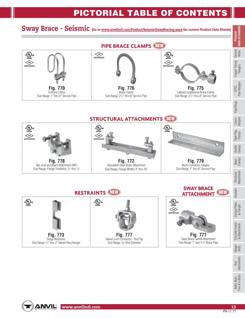
SWAY BRACEATTACHMENT
Fig. 771Sway Brace Swivel Attachment
Size Range: 1" and 11/4" Brace Pipe
RESTRAINTS
Fig. 773Surge Restrainer
Size Range: 3/4" thru 2" Swivel Ring Hanger
Fig. 777Swivel Joint Connector - Rod Tap
Size Range: 3/8" Rod Diameter
STRUCTURAL ATTACHMENTS
Fig. 778Bar Joist and Beam Attachment (WF)
Size Range: Flange Thickness 1/8" thru 3/4"
Fig. 772Adjustable Steel Beam Attachment
Size Range: Flange Widths 4" thru 15"
Fig. 779Multi-Connector Adapter
Size Range: 1" thru 8" Service Pipe
PIPE BRACE CLAMPS
Fig. 770Q Brace Clamp
Size Range: 1" thru 6" Service Pipe
Fig. 776Brace Clamp
Size Range: 21/2" thru 8" Service Pipe
Fig. 775Lateral/Longitudinal Brace Clamp
Size Range: 21/2" thru 8" Service Pipe
Sway Brace - Seismic (Go to www.anvilintl.com/Product/SeismicSwayBracing.aspx for current Product Data Sheets)
PH-11.11

PICTORIAL TABLE OF CONTENTS
www.anvilintl.com14
SPRING HANGERS
Fig. 82 & C-82Short Spring
Pages 142 - 143, 152 - 153
Fig. B-268 & C-268Standard Spring
Pages 142 - 143, 147 - 151
Fig. 98 & C-98Double Spring
Pages 142 - 143, 154 - 155
Triple Spring, Triple Spring-CRPages 156 - 157
Quadruple Spring, Quadruple Spring-CRPages 158 - 159
CONSTANT SUPPORTS
Model R Fig. 80-VVertical Constant SupportPages 168 - 174
Model R Fig. 81-HHorizontal Constant Support
Pages 175 - 181
HORIZONTAL TRAVELER & SWAY BRACE
Fig. 170Horizontal Traveler
Size Range: Available in four sizes to take loads to 20,700 (lbs.)All sizes provide for 12" of horizontal travel.
Page 184
Fig. 296, 297, 298, 301, 302, 303Sway Brace
Size Range: Preloads from 50 (lbs.) to 1,800 (lbs.) and maximum forcesfrom 200 (lbs.) to 7,200 (lbs.)
Pages 185 - 187
SWAY STRUT ASSEMBLY
Fig. 211, C-211, 640, C-640Sway Strut Assembly
Pages 188 - 189
Fig. 222 & C-222Mini-Sway Strut AssemblyPages 190 - 191
SNUBBERS
Fig. 3306 & 3307Hydraulic Shock and Sway Suppressor (Snubber)
Size Range: Seven standard sizes withload ratings from 350 (lbs.) to 120,000 (lbs)
Pages 192 - 195
Fig. 200, C-200, 201, C-201Hydraulic Shock and Sway Suppressor (Snubber)
Size Range: Nine standard sizes withload ratings from 3000 (lbs.) to 128,000 (lbs)
Pages 197 - 199
Fig. 312Tapered Pin
Size Range: 3/8" thru 21/2"Page 200
Spring Hangers –– Snubbers
PH-11.11

GENERAL NOTES
www.anvilintl.com 15
Copp
er Tu
bing
Ha
nger
sPi
pe R
ings
Clev
is Ha
nger
sSt
eel P
ipe
Clam
psSo
cket
Clam
psSt
ructu
ral
Attac
hmen
tsBr
acke
tsCe
iling
Plat
es&
Flan
ges
Conc
rete
Inse
rts&
Attac
hmen
tsHa
nger
Rods
Rod
Attac
hmen
tsBo
lts, N
uts,
Pins
& U
-Bol
tsBe
amCl
amps
Picto
rial
Tabl
e of C
onten
tsCP
VCPi
pe H
ange
rsGe
nera
lNo
tes
Standard Materials
Anvil catalog items are made from the following materials.
Hanger Classification Material Material Specifications (ASTM)
Beam Clamps
Malleable Iron A197Ductile Iron A536-77 Grade 65-45-12Carbon Steel - Stamped A36 or A1011, CS, Type A, B, or CCarbon Steel- Formed A575 Grade M1020Forged Steel A668 or A1030
Bolts, Nuts, Pins and U-BoltsCarbon Steel - Rod A36 or AISI 1006-1015Carbon Steel - Bolts A307Carbon Steel- Nuts A563
BracketsMalleable Iron A197Carbon Steel - Pre Galv. A653Carbon Steel - Structural Shapes and Plate A36
Ceiling Plates and FlangesPlastic N/AMalleable Iron A197Cast Iron A48 Grade 20 or A126
Clevis Hangers Carbon Steel - Stamped A1011, CS, Type A, B or CClevis Hangers - Pipe or Conduit Carbon Steel A569 Grade 1008-1010 or A525 or A526Clevis Hangers - Ductile Iron Pipe Carbon Steel A36, A569
Concrete Inserts and AttachmentsMalleable Iron A197Carbon Steel - Stamped A1011Carbon Steel - Formed and Fabricated A36 or A515 Grade 65-70
Copper Tubing HangersMalleable Iron A197Carbon Steel A1011, CS, Type A, B or C
Copper Tubing Hangers - Pipe Ring Carbon Steel A653CPVC Hangers Carbon Steel A1011, CS, Type BHanger Rods Carbon Steel A36 or A1006-1015Pipe Alingment Guides Carbon Steel A36 or A1011, CS, Type A, B, or CPipe Slides Carbon Steel - Structural Shapes or Plates A36
Pipe RingsMalleable Iron A197Carbon Steel A653
Pipe Roll - (2) Rod, Yoke & Chair Cast Iron A1010 or A1015Pipe Roll - Stands Cast Iron A48 Gr 20 or A126
Pipe Protection SaddlesCarbon Steel A36 or A1011, CS, Type A, B, or CAlloy Steel A387 Grade 22 Class 1 Annealed
Pipe Shields Carbon Steel A653Pipe Supports - Stanchions Carbon Steel Tube: A513 Grade 1020 or 1026, Plate:A36
Pipe Supports - SaddlesCarbon Steel A36Cast Iron A48 Grade 20 or A126
Rod AttachmentsMalleable Iron A197Carbon Steel A36Forged Steel A668 or A1030
Rod Attachments - Rod Couplings Carbon Steel A307 or A563Socket Clamps Carbon Steel A36
Socket Clamps- WashersCast Iron A126 Carbon Steel A36
Stainless Steel Hangers and Supports Refer to table note 1.Plate Stainless Steel A240 Type 304Pipe Stainless Steel A312 Type 304Rod and Pins Stainless Steel A276 Type 304Bolts Stainless Steel 18-8 StainlessNuts Stainless Steel 18-8 StainlessSteel Pipe Clamps- Offset and Extended Carbon Steel A36 or A570 Grade C/D or AISI 1020
Steel Pipe ClampsCarbon Steel - Stamped A36 or A1011, CS, Type A, B, or CCarbon Steel - Formed A36 or A515 Grade 65-70Chrome Molybdenum Steel A387 Grade 22
StrapsMalleable Iron A197Carbon Steel - Formed A36Carbon Steel - Stamped A1011, CS, Type A, B, or C
Structural Attachments - Washer Plates Carbon Steel A36 or AISI 1020 or A515 Grade 65-70
Structural AttachmentsCarbon Steel A36 or A515 Grade 65-70Malleable / Ductile A197, A536-77 Grade 65-45-12
TrapezeCarbon Steel - Structural Shapes A36Carbon Steel - HSS A500 Grade B or C
Notes: 1. Most Anvil hanger figure numbers are available in stainless steel on special order, primarily in type 304 and type 316. Items are limited. 2. Custom fabricated products can be furnished - to specifications provided by customer. 3. Standard material specifications are subject to change without notice.
PH-11.11

GENERAL NOTES
www.anvilintl.com16
Standard Galvanizing Practice
Electro-Plated Zinc (ASTM B633)This type of coating is recommended for use indoors in relatively dry areas. The steel is submersed in a bath of zinc salts, through the process of electrolysis, a coating of pure zinc adheres to the steel with a molecular bond. A maximum of .5 mills of zinc can be applied using this method. The threaded components and fasteners for Anvil hangers are furnished electro-plated.
Anvil offers 3 basic forms fo zinc coating on its hanger components 1) Electro-Plated Zinc (Electro-galvanized) 2) Pre-Galvanized Zinc 3) Hot Dipped Galvanized Note: The corrosion resistance of zinc is based on its thickness, the environment and the coating process used.
Pre-Galvanized Zinc (ASTM A653)This type of coating is suitable for extended exposure in dry or mildly corrosive atmospheres, but not gener-ally recommended for use outdoors in industrial environments. Also known as "mill galvanized" or "hot-dipped mill galvanized", pre-galvanized zinc coat-ings are produced by rolling the steel coils or sheets through molten zinc at the steel mill. The material is then cut or slit to size. Coating thickness is .90 ounces per square foot of steel surface. Zinc near the uncoated edges or weld areas becomes a sacrificial anode which protects the bare areas. Anvil uses this type of material on our Fig. 167 shields and Fig. 69 swivel ring hangers.
Hot-Dip Galvanized(ASTM 123 or ASTM 153)Recommended for prolonged outdoor exposure and will usually protect steel in most atmospheric environments. After fabrication, the part is immersed in a bath of molten zinc. A metallurgical bond is formed, resulting in a zinc coating that coats all surfaces including edges. Anvil's standard galvanizing practice for our Fig. 261 riser clamps and Fig. 212 medium pipe clamps is hot-dip galvanized.
PH-11.11
GENERAL NOTES
www.anvilintl.com 17
Copp
er Tu
bing
Ha
nger
sPi
pe R
ings
Clev
is Ha
nger
sSt
eel P
ipe
Clam
psSo
cket
Clam
psSt
ructu
ral
Attac
hmen
tsBr
acke
tsCe
iling
Plat
es&
Flan
ges
Conc
rete
Inse
rts&
Attac
hmen
tsHa
nger
Rods
Rod
Attac
hmen
tsBo
lts, N
uts,
Pins
& U
-Bol
tsBe
amCl
amps
Picto
rial
Tabl
e of C
onten
tsCP
VCPi
pe H
ange
rsGe
nera
lNo
tes
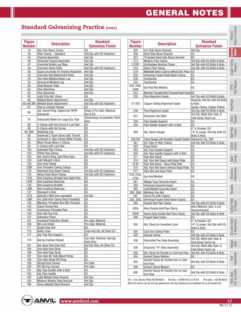
Standard Galvanizing Practice (cont.)
EG = Zinc Electro Plate ASTM B633 Hot Dip = ASTM A123 or A153 Pre-Galv. = ASTM A653Most EG items can be hot dip galvanized. Hot dip fasteners are available as is all thread rod.
Figure Number Description Standard
Galvanize Finish14 Adj. Side Beam Clamp EG40 Riser Clamp – Standard Hot Dip with EG Fasteners45 Channel Assembly Hot Dip46 Universal Trapeze Assembly Hot Dip47 Concrete Single Lug Plate Hot Dip49 Concrete Clevis Plate Hot Dip with EG Fasteners50 Equal Leg Angle for Trapeze Assembly Hot Dip52 Concrete Rod Attachment Plate Hot Dip54 Two Hole Welding Beam Lug Hot Dip55 Structural Welding Lug Hot Dip60 Steel Washer Plate Hot Dip62 Pipe Stanchion Hot Dip63 Pipe Stanchion Hot Dip65 Light Duty Adj. Clevis EG66 Welded Beam Attachment Hot Dip
66 with BN Welded Beam Attachment Hot Dip with EG Fasteners67 Pipe or Conduit Hanger EG
69 Adj. Swivel Ring, Tapped per NFPA Standards
Strap is Pre-Galv. Material, Nut is EG
76 Fabricated Roller for Large Dia. Pipe Galvanizing not possible, Paint Only
86 C-Clamp with Set Screw & Lock Nut EG88 C-Clamp with Set Screw EG
89, 89X Retaining Clip EG92 Universal C-Type Clamp (Std. Throat) EG93 Universal C-Type Clamp (Wide Throat) EG94 Wide Throat Beam C-Clamp EG95 C-Clamp with Lock Nut EG
100 Extended Pipe Clamp Hot Dip with EG Fasteners103 Offset Pipe Clamp Hot Dip with EG Fasteners104 Adj. Swivel Ring, Split Ring Type EG120 Light Weight U-Bolt EG126 One-Hole Clamp EG
128R Rod Threaded Ceiling Flange EG133 Standard Duty Beam Clamp Hot Dip with EG Fasteners134 Heavy Duty Beam Clamp Hot Dip with EG Fasteners135E Rod Coupling Straight less Sight Hole EG135R Rod Coupling Reducing EG136 Rod Coupling Straight EG
136R Rod Coupling Reducing EG137 Standard U-Bolt EG
137S Special U-Bolt (non-standard) Hot Dip138R Ext. Split Pipe Clamp (Rod Threaded) EG140 Machine Threaded Rod (RH Threads) EG142 Coach Screw Rod EG146 Continuous Threaded Rod EG148 Rod with Eye End EG157 Extension Piece EG167 Insulated Protection Shield Pre-Galv. Material168 Rib-Lok Shield Pre-Galv. Material171 Single Pipe Roll EG175 Roller Chair Chair-Hot Dip, All Other EG177 Adj. Pipe Roll Support EG
178 Spring Cushion Hanger Can Galv. Retainer, Springs Paint Only
181 Adj. Steel Yoke Pipe Roll Hot Dip Yoke, All Other EG185 One Hole Pipe Strap EG186 Two Hole Pipe Strap EG187 Two Hole 90˚ Side Mount Strap EG188 Two Hole Stand Off Strap EG189 Straight Eye Socket Pre-Galv.190 Off-Set Eye Socket Pre-Galv.191 Adj. Pipe Saddle with U-Bolt EG192 Adj. Pipe Saddle EG194 Light Welded Steel Bracket Hot Dip195 Medium Welded Steel Bracket Hot Dip199 Heavy Welded Steel Bracket Hot Dip
Figure Number Description Standard
Galvanize Finish202 Iron Side Beam Bracket Hot Dip206 Steel Side Beam Bracket EG207 Threaded Steel Side Beam Bracket EG212 Medium Pipe Clamp Hot Dip with EG Bolts & Nuts
212FP Earthquake Bracing Clamp Hot Dip with EG Bolts & Nuts216 Heavy Pipe Clamp Hot Dip with EG Bolts & Nuts218 Malleable Beam Clamp without Ext. Piece EG228 Universal Forged Steel Beam Clamp EG230 Turnbuckle EG233 Turnbuckle EG
248, 248L, 248X Eye Rod Not Welded EG
253 Machine Threaded Rod (Threaded Both Ends) EG255 Pipe Alignment Guide Hot Dip with EG Bolts & Nuts
CT-255 Copper Tubing Alignment GuideHousing: Hot Dip with EG Bolts & NutsSpider Clamp: Copper Plated
256 Pipe Alignment Guide Hot Dip with EG Bolts & Nuts
257 Structural Tee Slide Hot Dip, Weld after Galv. & Cold Spray Touch-up
258 Pipe Saddle Support EG259 Pipe Saddle Support with U-Bolt EG
260 Adj. Clevis Hanger8" & Smaller: EG10" & Larger: Hot Dip with EG Bolts & Nuts
260 ISS Clevis Hanger with Insulation Saddle System Reference Fig. 260261 Ext. Pipe or Riser Clamp Hot Dip with EG Bolts & Nuts262 Strap Short EG264 Adj. Pipe Saddle Support EG265 Adj. Pipe Saddle Support with U-Bolt EG271 Pipe Roll Stand EG274 Adj. Pipe Roll Stand with Base Plate EG
274P Pipe Roll Stand - Base Plate Only EG275 Adj. Pipe Roll Stand without Base Plate EG277 Pipe Roll and Base Plate EG
278, 278L, 278X Eye Rod Welded EG
281 Wedge Type Concrete Insert EG282 Universal Concrete Insert EG285 Light Weight Concrete Insert EG
290, 290L Weldless Eye Nut EG291 Clevis Pin with Cotters EG
292, 292L Universal Forged Steel Beam Clamp EG295 Double Bolt Pipe Clamp Hot Dip with EG Bolts & Nuts
295A Alloy Double Bolt Pipe Clamp Alloy Material, Galv. is notRecommended
295H Heavy Duty Double Bolt Pipe Clamp Hot Dip with EG Bolts & Nuts299 Forged Steel Clevis EG
300 Adj. Clevis for Insulated Lines8" & Smaller: EG10" & Larger: Hot Dip with EG Bolts & Nuts
395 Cast Iron Ceiling Plate EG432 Special Clamp Hot Dip with EG Bolts & Nuts
436 Fabricated Tee Slide Assembly Hot Dip, Weld after Galv. & Cold Spray Touch-up
439 Structural "H" Slide Assembly Hot Dip, Weld after Galv. & Cold Spray Touch-up
590 Adj. Clevis for Ductile or Cast Iron Pipe Hot Dip with EG Bolts & Nuts594 Socket Clamp Washer EG
595 Socket Clamp for Ductile Iron or Cast Iron Pipe Hot Dip with EG Bolts & Nuts
599 Socket Clamp Washer EG
600 Socket Clamp for Ductile Iron or Cast Iron Pipe Hot Dip with EG Bolts & Nuts
PH-11.11

COPPER TUBING HANGERS
www.anvilintl.com18
Fig. CT-69 Adjustable Swivel Ring
Size Range: 1⁄2" through 4"Material: Carbon steelFinish: Copper platedService: Recommended for suspension of non-insulated stationary copper tube.Approvals: Complies with Federal Specification A-A-1192A (Type 10) WW-H-171-E (Type 10), ANSI/MSS SP-69 and MSS SP-58 (Type 10).Features:
• Threads are countersunk so that they cannot become burred or damaged.• Knurled swivel nut provides vertical adjustment after piping is in place.• Captured swivel nut will not fall off.
Ordering: Specify nominal tube size, figure number, name and finish.Note: Metric nut available upon request.
FIG. CT-69: LOADS (LBS) • WEIGHT (LBS) • DIMENSIONS (IN)
Tube Size Max Load Weight B C F GWidth
1⁄2
300
0.10 3 23⁄16 17⁄8
5/8
3⁄4 0.10 213⁄16 2 19⁄16
1 0.10 211⁄16 113⁄16 11⁄4
11⁄4 0.10 21⁄2 15⁄8 15⁄16
11⁄2 0.10 211⁄16 113⁄16 1
2 0.11 37⁄16 21⁄2 11⁄2
21⁄2525
0.25 313⁄16 215⁄16 111⁄16
3/43 0.27 41⁄4 33⁄8 17⁄8
4 650 0.48 43⁄8 31⁄2 11/2
Note: Reflects changes in rod diameter from previously published data per recent revisions in MSS-SP-58 & 69
3⁄8"
BCF
CL
G
B
CF
CL
F
3⁄8"
G
11/2" through 4" pipe
1/2" through 11/4" pipe
PH-11.11

COPPER TUBING HANGERS
www.anvilintl.com 19
Copp
er T
ubin
g Ha
nger
sPi
pe R
ings
Clev
is Ha
nger
sSt
eel P
ipe
Clam
psSo
cket
Clam
psSt
ructu
ral
Attac
hmen
tsBr
acke
tsCe
iling
Plat
es&
Flan
ges
Conc
rete
Inse
rts&
Attac
hmen
tsHa
nger
Rods
Rod
Attac
hmen
tsBo
lts, N
uts,
Pins
& U
-Bol
tsBe
amCl
amps
Picto
rial
Tabl
e of C
onten
tsCP
VCPi
pe H
ange
rsGe
nera
lNo
tes
Fig. CT-65 Light Duty Adjustable Clevis
Size Range: 1⁄2" through 4"Material: Carbon steelFinish: Copper platedService: Recommended for suspension of non-insulated, stationary copper tube.Approvals: Complies with Federal Specification WW-H-171-E (Type 12).Installation:
(1) Adjustment may be made either before or after tubing is in place without temporary support of pipe.(2) Hanger rod and nuts may be locked into position after adjustment
by use of the upper nut.Features: Provides for adjustment up to 1 7⁄8".Ordering: Specify nominal tube size, figure number, name and finish
FIG. CT-65: LOADS (LBS) • WEIGHT (LBS) • DIMENSIONS (IN)
TubeSize Max Load Weight Rod Size
A B C D Rod Take Out - E
Adjustment F
G WidthLower
1⁄2150
0.09
3⁄8
11⁄2 127⁄32 17⁄16 11⁄16 5⁄16 5/8
3⁄4 0.10 111⁄16 23⁄32 19⁄16 11⁄4 7⁄16
3/4
1
250
0.17 17⁄8 213⁄32 15⁄8 17⁄16 1⁄2
11⁄4 0.18 25⁄32 213⁄16 13⁄4 111⁄16 5⁄8
11⁄2 0.21 217⁄32 33⁄8 115⁄16 21⁄16 13⁄16
2 0.26 311⁄32 417⁄32 25⁄16 27⁄8 13⁄16
21⁄2350
0.48 327⁄32 59⁄32 23⁄4 31⁄4 15⁄16
3 0.55 415⁄32 67⁄32 3 37⁄8 15⁄8
4 400 0.60 431⁄32 631⁄32 31⁄4 43⁄8 17⁄8
Note: 1) Reflects changes in rod diameter from previously published data per recent revisions in MSS-SP-58 & 69.2) 31/2" tube size alternate - 31/2" Fig. 65 galvanized.
A
F
B
CE
CL
G
PH-11.11

COPPER TUBING HANGERS
www.anvilintl.com20
Fig. CT-138R Extension Split Tubing Clamp (Rod Threaded)
Size Range: 1⁄2" through 2"Material: Malleable ironFinish: Copper platedService: Recommended for suspension of non-insulated stationary copper tube.Approvals: Complies with Federal Specification A-A-1192A (Type 12) WW-H-171-E (Type 25), ANSI/MSS SP-69 and MSS SP-58 (Type 12).Installation:• Permanent installation of clamp may be made before the tubing is placed in position.• Final installation is attained by swinging the lower portion of the hinged clamp up under the tubing and inserting a single screw securely.Features:• Hinged design provides for economical installation.• Designed to provide a tight fit on copper tubing.Ordering: Specify nominal tube size, figure number, name.
FIG. CT-138R: LOADS (LBS) • WEIGHT (LBS) • DIMENSIONS (IN)
Tube Size Max Load Weight B1⁄2
180
0.10 3⁄43⁄4 0.12 7⁄81 0.14 1
11⁄4 0.18 11⁄811⁄2 0.22 11⁄42 0.36 19⁄16
B
3⁄8"
CL
Fig. CT-128R Rod Threaded Ceiling Flange
Size Range: 3⁄8" and 1⁄2"Material: Malleable ironFinish: Copper platedService: Recommended for attachment to wood beams or ceiling.Ordering: Specify rod size, figure number, name.
FIG. CT-128R: LOADS (LBS) • WEIGHT (LBS) • DIMENSIONS (IN)
Rod Size A Max Load Weight
ScrewsQuantity Size No.
3⁄8180 0.16 2 12
1⁄2
35⁄16"
13⁄8"
21⁄4"
A
1⁄2"
3⁄16"
PH-11.11

COPPER TUBING HANGERS
www.anvilintl.com 21
Copp
er T
ubin
g Ha
nger
sPi
pe R
ings
Clev
is Ha
nger
sSt
eel P
ipe
Clam
psSo
cket
Clam
psSt
ructu
ral
Attac
hmen
tsBr
acke
tsCe
iling
Plat
es&
Flan
ges
Conc
rete
Inse
rts&
Attac
hmen
tsHa
nger
Rods
Rod
Attac
hmen
tsBo
lts, N
uts,
Pins
& U
-Bol
tsBe
amCl
amps
Picto
rial
Tabl
e of C
onten
tsCP
VCPi
pe H
ange
rsGe
nera
lNo
tes
A
B
C
F
CL
G
B
CF
A
CL
G
1/2" & 3/4" tube1/2" through 1" Felted Ring
1" through 6" tube11/4" through 6" Felted Ring
Fig. 69F Adjustable Swivel Ring, Felt Lined
Size Range: 1⁄2" through 6" copper tubeMaterial: Carbon steel and felt with adhesive backingFinish: GalvanizedService: Recommended for suspension of non-insulated stationary copper tubing.Maximum Temperature: 120° FApprovals: Complies with Federal Specification A-A-1192A (Type 10) WW-H-171-E (Type 10), ANSI/MSS SP-69 and MSS SP-58 (Type 10).Features:
• The layer of felt separates the copper tubing from the steel ring for electrolytic resistance and also minimizes noise and vibration.• Threads are countersunk so they cannot become burred or damaged.• Knurled swivel nut provides vertical adjustment after tubing is in place.• The captured nut is permanent in the bottom portion of band, allowing the hanger to be opened during installation if desired, but not allowing the nut to fall out.
Ordering: Specify felt ring size, figure number and name.
FIG. 69F: LOADS (LBS) • WEIGHT (LBS) • DIMENSIONS (IN)
Tube Size FeltedRing Size Max Load Rod Size A B C F G
Width Weight
1⁄2 1⁄2 - 1
300
3⁄8
23⁄4 17⁄8 13⁄8
5/8
0.103⁄4 25⁄8 111⁄16 11⁄8 0.101
11⁄427⁄16 19⁄16 113⁄16 0.10
11⁄4 21⁄2 15⁄8 13⁄16 0.10 11⁄2 11⁄2 25⁄8 13⁄4 3⁄4 0.102 2 31⁄8 21⁄4 1 0.10
21⁄2 21⁄2525
37⁄8 25⁄8113⁄16
3/4
0.203 3 33⁄4 27⁄8 0.204 4 650 45⁄8 33⁄4 19⁄16 0.305 5
1,000 1⁄251⁄4 45⁄16 15⁄8 0.54
6 6 611⁄16 59⁄16 23⁄8 0.65
FELT LINED RING: IPS SIZING • DIMENSIONS (IN)
Pipe Size Felted Ring Size1⁄2 1⁄2 - 13⁄4 11⁄41 11⁄4
11⁄4 211⁄2 22 21⁄2
21⁄2 33 44 55 6
PH-11.11

COPPER TUBING HANGERS
www.anvilintl.com22
Fig. 67F Copper Tube Felt Lined Hanger
Size Range: 1⁄2" through 6" copper tubeMaterial: Carbon steel and felt with adhesive backingFinish: GalvanizedService: Can be suspended by hanger rod or attached to wall. “T” slot in hanger permits side bolt to be installed after installation and setting of pipe.Maximum Temperature: 120˚F Approvals: Complies with Federal Specification A-A-1192A (Type 5), ANSI/MSS SP-69 and MSS SP-58 (Type 5).Features: The layer of felt separates the copper tubing from the steel strap forelectrolytic resistance and also minimizes noise and vibration.Components: Strap and bolt with nut – assembled.Ordering: Specify felt hanger size, figure number and name.
FIG. 67F: LOADS (LBS) • WEIGHT (LBS) • DIMENSIONS (IN)
TubeSize
FeltHanger Size
Load Rating
Rod Size A B C D E F G H
Width Weight
1⁄2 3⁄4
400 3⁄8
21⁄2
1⁄4
15⁄8
7⁄16
15⁄16 13⁄4
1
0.22
3⁄4 1 211⁄16 111⁄16 11⁄2 115⁄16 0.25
1 11⁄4 213⁄16 113⁄16 15⁄8 21⁄8 0.27
11⁄4 11⁄4 31⁄8 17⁄8 2 29⁄16 0.27
11⁄2 11⁄2 37⁄16 21⁄16 25⁄16 23⁄4 0.29
2 2 39⁄16 2 27⁄16 215⁄16 0.31
21⁄2 21⁄2500 1⁄2
45⁄16
3⁄8
25⁄16
9⁄16
31⁄16 31⁄2
11/4
0.71
3 3 43⁄4 21⁄2 31⁄2 41⁄16 0.78
4 4550 5⁄8
61⁄16 31⁄8 45⁄8 53⁄16 1.39
5 5 611⁄16 33⁄16 51⁄8 513⁄16 1.66
6 6 600 3⁄4 73⁄4 39⁄16 515⁄16 63⁄4 2.26
F
CL
A
GD
E
C
B
CL
H Alternate InstallationBolt/Screw to Vertical Support
FELT LINED HANGER: IPS SIZING • DIMENSIONS (IN)
Pipe Size Felted Hanger Size3⁄4 11⁄41 11⁄2
11⁄4 211⁄2 22 21⁄2
21⁄2 33 44 55 6
PH-11.11

COPPER TUBING HANGERS
www.anvilintl.com 23
Copp
er T
ubin
g Ha
nger
sPi
pe R
ings
Clev
is Ha
nger
sSt
eel P
ipe
Clam
psSo
cket
Clam
psSt
ructu
ral
Attac
hmen
tsBr
acke
tsCe
iling
Plat
es&
Flan
ges
Conc
rete
Inse
rts&
Attac
hmen
tsHa
nger
Rods
Rod
Attac
hmen
tsBo
lts, N
uts,
Pins
& U
-Bol
tsBe
amCl
amps
Picto
rial
Tabl
e of C
onten
tsCP
VCPi
pe H
ange
rsGe
nera
lNo
tes
Fig. CT-121 Copper Tubing Riser Clamp
Size Range: 1⁄2" through 4"Material: Carbon steelFinish: Copper platedService: Recommended for support and steadying ofcopper tube risers, either insulated or non-insulated.This product is not intended for use with hanger rods.Approvals: Complies with Federal Specification A-A-1192A(Type 8), WW-H-171-E (Type 8), ANSI/MSS SP-69 andMSS SP-58 (Type 8).Service: For support and steadying of copper tubing risers.Installation: Clamp is fitted and bolted preferably below acoupling or fitting on the tubing. Do not over tighten bolts.Features: Rounded ears provide greater safety for personnel.Ordering: Specify tube size, figure number, name.
FIG. CT-121: LOADS (LBS) • WEIGHT (LBS) • DIMENSIONS (IN) • TORQUE (FT-LBS)
Tube Size Max Load Weight L GWidth Bolt Size Torque Values
1⁄275
0.52 61⁄21 5⁄16 11
3⁄4 0.56 71 120 0.94 93⁄8
11⁄4 3⁄8 21
11⁄4150
0.98 95⁄811⁄2 1.50 102 1.50 103⁄8
21⁄2
300
1.70 1113⁄16
3 1.80 111⁄231⁄2 1.90 124 2.60 13 1 1⁄2 46
Note: Minimum loads per MSS SP only applicable to 11/4" and up.
L
B
C
G
CL
PH-11.11

COPPER TUBING HANGERS
www.anvilintl.com24
Fig. CT-255 Copper Tubing Alignment Guide
Size Range: 1" through 4"Material: Carbon steelFinish: Plain or Galvanized housing with copper plated finish on spider clamp.Service: For maintaining alignment of tubing through its axial expansion and contraction cycles. Normally, two or more pipe alignment guides are used on a single tubing run to avoid a pivoting effect within the tubing system. Consult the Expansion Joint Manufacturers Association or the Copper Tube Manufacturers for additional guidelines of spacing requirements of intermediate guides. Supports are usually required between intermediate guides to comply with standard support practices.Maximum Temperature: 400° FInstallation:
(1) Attach outer housing to structure by bolting or welding.(2) Remove upper section of housing to open position.(3) Attach spider clamp to tube and completely insulate.(4) Set tube and spider clamp into outer housing.(5) Replace upper section of housing to closed position and secure.
Note: Spider attachments to tube must be properly located during installation to insure that a minimum of one-half the spider width remains within the length of the outer housing for all conditions of operation. If larger travels are required, special guides can be furnished to special order.How to size: Size by nominal tube size and insulation thickness in accordance with the selection table.Ordering: Specify size number, tube size, insulation thickness, figure number, name and finish.Caution: The primary function of the Figure CT-255 is to maintain axialalignment of a system. Other components should be incorporated into thesystem to carry the primary loading of the system. Guides are designed suchthat minor loading amounts may be transferred to the guide in any givendirection, up to 20% of dead weight load for typical maximum spans of agiven pipe diameter.
Tube Size (in) L (in) Maximum Movement
1" to 4" 4 4
PH-11.11

COPPER TUBING HANGERS
www.anvilintl.com 25
Copp
er T
ubin
g Ha
nger
sPi
pe R
ings
Clev
is Ha
nger
sSt
eel P
ipe
Clam
psSo
cket
Clam
psSt
ructu
ral
Attac
hmen
tsBr
acke
tsCe
iling
Plat
es&
Flan
ges
Conc
rete
Inse
rts&
Attac
hmen
tsHa
nger
Rods
Rod
Attac
hmen
tsBo
lts, N
uts,
Pins
& U
-Bol
tsBe
amCl
amps
Picto
rial
Tabl
e of C
onten
tsCP
VCPi
pe H
ange
rsGe
nera
lNo
tes
Fig. CT-255 Copper Tubing Alignment Guide (cont.)
Guide Size No.
Dimensions (in)
A B C D E H T
A 813⁄16 63⁄4 8 45⁄8 53⁄4
5⁄8 1⁄4B 1013⁄16 83⁄4 10 53⁄8 7
C 135⁄16 111⁄4 127⁄16 65⁄8 73⁄4
D 157⁄8 133⁄8 1413⁄16 715⁄16 93⁄4 3⁄4 3⁄8
Tube Size
Guide Size Number
Insulation Thickness (in)
1 11⁄2 2 21⁄2 3 41⁄2 A A A A – –
3⁄4 A A A A – –
1 A A A A C C
11⁄4 A A A C C C
11⁄2 A A A C C C
2 B B B B C C
21⁄2 B B B B C C
3 B B B B D D
31⁄2 B B B D D D
4 B B B D D D
Tube
A
E
C
4
B
J INSULATION THICKNESSH DIA
4 HOLES
D
T
24
CL CL
4
J INSULATION THICKNESSH DIA
4 HOLESE
A
B
Tube
C
24
DT
Copper Tubing Alignment Guide, Figure CT-255, Size A & B Copper Tubing Alignment Guide, Figure CT-255, Size C thru D
PH-11.11

CPVC PIPE HANGERS
www.anvilintl.com26
Fig. 185 One Hole Pipe Strap
Size Range: 3⁄4" through 2"Finish: Galvanized steelService: Hanger for CPVC pipe in the horizontal position on the side of structuralwood beams and Steel 20 Ga. (min) with hanger tab in the upward position only (Fig. A).It can also be used as a guide to limit movement of vertical CPVC pipe with the tabin the horizontal position.Approvals: UL and ULC Listed.Installation:
• Place hanger over pipe.• Secure hanger to mounting surface with screws provided.• Steel applications require one (1) #14 x 1" hex washer head self-drilling TEK screw. Not Supplied. Part Number STD-0090.
Features: • Beveled edge design helps protect the CPVC pipe from any rough surface.• Easily attaches to wood structure with #10 x 1" hex washer head self threading screw supplied with product. No pre-drilling required.
Ordering: Specify CPVC pipe size, figure number and description.
FIG. 185: WEIGHT (LBS) • DIMENSIONS (IN)
CPVCPipe Size A B øC E F Max. Hanger
Spacing (FT.)Approx.
Weight/100 (lbs)3⁄4 17⁄16 21⁄2 1⁄4 11⁄8 11⁄4 51⁄2 8
1 13⁄4 27⁄8 1⁄4 11⁄8 11⁄2 6 9
11⁄4 111⁄16 3 1⁄4 11⁄8 17⁄8 61⁄2 10
11⁄2 17⁄8 37⁄16 1⁄4 11⁄8 21⁄8 7 12
2 2 37⁄8 1⁄4 11⁄8 25⁄8 8 14
Fig. A
PH-11.11

CPVC PIPE HANGERS
www.anvilintl.com 27
Copp
er Tu
bing
Ha
nger
sPi
pe R
ings
Clev
is Ha
nger
sSt
eel P
ipe
Clam
psSo
cket
Clam
psSt
ructu
ral
Attac
hmen
tsBr
acke
tsCe
iling
Plat
es&
Flan
ges
Conc
rete
Inse
rts&
Attac
hmen
tsHa
nger
Rods
Rod
Attac
hmen
tsBo
lts, N
uts,
Pins
& U
-Bol
tsBe
amCl
amps
Picto
rial
Tabl
e of C
onten
tsCP
VCPi
pe H
ange
rsGe
nera
lNo
tes
FIG. 186: WEIGHT (LBS) • DIMENSIONS (IN)
CPVCPipe Size A B øC E F Max. Hanger
Spacing (FT.)Approx.
Weight/100 (lbs)3⁄4 1 213⁄16 1⁄4 11⁄8 11⁄8 51⁄2 5
1 11⁄4 31⁄4 1⁄4 11⁄8 11⁄2 6 6
11⁄4 15⁄16 33⁄8 1⁄4 11⁄8 111⁄16 61⁄2 7
11⁄2 19⁄16 37⁄8 1⁄4 11⁄8 21⁄8 7 8
2 113⁄16 45⁄16 1⁄4 11⁄8 29⁄16 8 9
Fig. 186 Two Hole Pipe Strap
Size Range: 3⁄4" through 2"Finish: Galvanized steelService: Hanger for CPVC pipe in the horizontal position on the bottomand side of structural wood beams, composite beams and Steel 20 Ga. (min.)(Fig. A, C respectively). Can be used as a restrainer when installed on top ofstructural wood beams (Fig. B), for limiting pipe movement due to thrustloads during sprinkler system start-up. It can also be used as a guide tolimit movement for pipe in the vertical position. When used on compositewood beams, web thickness must be 3/8" or greater.Approvals: UL and ULC Listed.Installation:
• Snap hanger over pipe. Dimples will prevent hanger from falling off pipe.• Secure hanger to mounting surface with screws provided.• Do not make adjustments to hanger mounting flanges that result in clamping the pipe to the mounting surface. Pipe must be allowed to move freely through hanger.• Steel applications require two (2) #14 x 1" hex washer head self-drilling TEK screws. Not Supplied. Part Number STD-0090.
Features: • Dimples secure hanger to pipe for quick installation.• Beveled edge design helps protect the CPVC pipe from any rough surface.• Easily attaches to wood structure with #10 x 1" hex washer head self threading screw supplied with product. No pre-drilling required.
Ordering: Specify CPVC pipe size, figure number and description.Fig. A
Fig. B Fig. C
PH-11.11

CPVC PIPE HANGERS
www.anvilintl.com28
Fig. 187 Two Hole 90˚ Side Mount Strap
Size Range: 3⁄4" through 2"Finish: Galvanized steelService: Hanger for CPVC pipe in the horizontal position on the bottom ofstructural wood beams and Steel 20 Ga. (min.) (Fig. A). Can be used as arestrainer, only in Steel 20 Ga. (min) (Fig. B). During installation, adjust hangermounting flanges such that pipe contacts both mounting surface and hanger,minimizing vertical pipe movement. Approvals: UL and ULC Listed.Installation:
• Snap hanger over pipe. Dimples will prevent hanger from falling off pipe.• Secure hanger to mounting surface with screws provided.• Do not anchor tightly to mounting surface. Pipe must be allowed to move freely through hanger.• Steel applications require two (2) #14 x 1" hex washer head self-drilling TEK screws. Not Supplied. Part Number STD-0090.
Features: • Beveled edge design helps protect the CPVC pipe from any rough surface.• Easily attaches to wood structure with #10 x 1" hex washer head self threading screw supplied with product. No pre-drilling required.
Ordering: Specify CPVC pipe size, figure number and description.
Fig. BFig. A
FIG. 187: WEIGHT (LBS) • DIMENSIONS (IN)
CPVCPipe Size A B øC E F Max. Hanger
Spacing (FT.)Approx.
Weight/100 (lbs)3⁄4 1 11⁄2 1⁄4 11⁄8 23⁄4 51⁄2 5
1 11⁄8 11⁄2 1⁄4 11⁄8 213⁄16 6 6
11⁄4 15⁄16 13⁄4 1⁄4 11⁄8 31⁄4 61⁄2 7
11⁄2 11⁄2 17⁄8 1⁄4 11⁄8 31⁄2 7 8
2 13⁄4 2 1⁄4 11⁄8 37⁄8 8 9
PH-11.11

CPVC PIPE HANGERS
www.anvilintl.com 29
Copp
er Tu
bing
Ha
nger
sPi
pe R
ings
Clev
is Ha
nger
sSt
eel P
ipe
Clam
psSo
cket
Clam
psSt
ructu
ral
Attac
hmen
tsBr
acke
tsCe
iling
Plat
es&
Flan
ges
Conc
rete
Inse
rts&
Attac
hmen
tsHa
nger
Rods
Rod
Attac
hmen
tsBo
lts, N
uts,
Pins
& U
-Bol
tsBe
amCl
amps
Picto
rial
Tabl
e of C
onten
tsCP
VCPi
pe H
ange
rsGe
nera
lNo
tes
Fig. 188 Two Hole Stand Off Strap
Size Range: 3⁄4" through 2"Finish: Galvanized steelService: Support for CPVC pipe off the face of structural wood beams (Fig. A)eliminates the use of back-up blocks. It can also be used as a hanger for CPVCpipe in the horizontal position on the bottom of structural wood beams andSteel 20 Ga. (min.) (Fig. B).Approvals: UL and ULC Listed.Installation:
• Snap hanger over pipe.• Position hanger back around pipe but allow for pipe movement.• Secure hanger to mounting surface with screws provided. Recheck to insure that the pipe is allowed to move freely through hanger.• Steel applications require two (2) #14 x 1" hex washer head self-drilling TEK screws. Not Supplied. Part Number STD-0090.
Features: • Beveled edge design helps protect the CPVC pipe from any rough surface.• Easily attaches to wood structure with #10 x 1" hex washer head self threading screw supplied with product. No pre-drilling required.• Eliminates wooden spacer blocks.
Ordering: Specify CPVC pipe size, figure number and description.
Fig. B
FIG. 188: WEIGHT (LBS) • DIMENSIONS (IN)
CPVCPipe Size A B øC E F Max. Hanger
Spacing (FT.)Approx.
Weight/100 (lbs)3⁄4 15⁄16 31⁄4 1⁄4 11⁄8 23⁄4 51⁄2 5
1 13⁄8 33⁄8 1⁄4 11⁄8 3 6 6
11⁄4 11⁄2 311⁄16 1⁄4 11⁄8 35⁄16 61⁄2 7
11⁄2 17⁄8 43⁄8 1⁄4 11⁄8 39⁄16 7 8
2 2 41⁄2 1⁄4 11⁄8 41⁄8 8 9
Fig. A
Ordering: Specify CPVC pipe size, figure number
PH-11.11

PIPE RINGS
www.anvilintl.com30
Fig. 108 Split Pipe Ring
Size Range: 3⁄8" through 8"Material: Malleable ironFinish: PlainService: Recommended for suspension of non-insulated stationary pipe lines or conduit. May be used with rod socket Fig. 110R or turnbuckle adjuster Fig. 114.Maximum Temperature: 450° FApprovals: Complies with Federal Specification A-A-1192A (Type 11) WW-H-171-E (Type 11), ANSI/MSS SP-69 and MSS SP-58 (Type 11).Features:
• Permits installation before or after pipe is in place.• Provides economical installation.• Permits use of universally adaptable parts.
Ordering: Specify pipe size, figure number, name.
FIGURE 108: LOADS (LBS) • WEIGHT (LBS) • DIMENSIONS (IN)
Pipe Size Max Load Weight C Bolt Size
3⁄8200
0.06 3⁄4 #10 x 7⁄81⁄2 0.09 15⁄16
1⁄4 x 13⁄4
300
0.11 11⁄8
1 0.13 11⁄4
11⁄4 0.18 19⁄16
11⁄2 0.26 111⁄16
1⁄4 x 11⁄4
2 0.33 21⁄16
2 1⁄2
450
0.44 21⁄4
3 0.63 23⁄4
31⁄2 0.81 31⁄8
4520
0.97 35⁄83⁄8 x 2
5 1.50 41⁄2
6 1,300 2.60 57⁄161⁄2 x 2
8 1,800 5.20 63/8
C
CL
PH-11.11
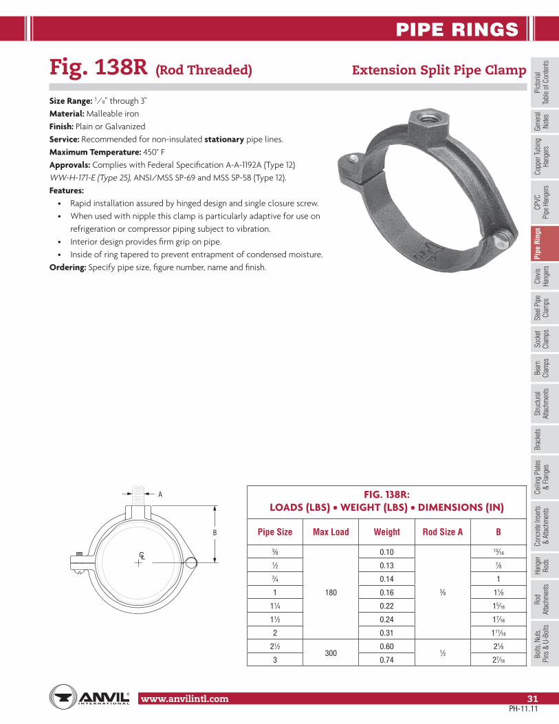
PIPE RINGS
www.anvilintl.com 31
Copp
er Tu
bing
Ha
nger
sPi
pe R
ings
Clev
is Ha
nger
sSt
eel P
ipe
Clam
psSo
cket
Clam
psSt
ructu
ral
Attac
hmen
tsBr
acke
tsCe
iling
Plat
es&
Flan
ges
Conc
rete
Inse
rts&
Attac
hmen
tsHa
nger
Rods
Rod
Attac
hmen
tsBo
lts, N
uts,
Pins
& U
-Bol
tsBe
amCl
amps
Picto
rial
Tabl
e of C
onten
tsCP
VCPi
pe H
ange
rsGe
nera
lNo
tes
Fig. 138R (Rod Threaded) Extension Split Pipe Clamp
Size Range: 3⁄8" through 3"Material: Malleable ironFinish: Plain or GalvanizedService: Recommended for non-insulated stationary pipe lines.Maximum Temperature: 450° FApprovals: Complies with Federal Specification A-A-1192A (Type 12) WW-H-171-E (Type 25), ANSI/MSS SP-69 and MSS SP-58 (Type 12).Features:
• Rapid installation assured by hinged design and single closure screw.• When used with nipple this clamp is particularly adaptive for use on refrigeration or compressor piping subject to vibration.• Interior design provides firm grip on pipe.• Inside of ring tapered to prevent entrapment of condensed moisture.
Ordering: Specify pipe size, figure number, name and finish.
FIG. 138R:LOADS (LBS) • WEIGHT (LBS) • DIMENSIONS (IN)
Pipe Size Max Load Weight Rod Size A B
3⁄8
180
0.10
3⁄8
13⁄16
1⁄2 0.13 7⁄83⁄4 0.14 1
1 0.16 11⁄8
11⁄4 0.22 15⁄16
11⁄2 0.24 17⁄16
2 0.31 111⁄16
21⁄2300
0.601⁄2
21⁄8
3 0.74 27⁄16
B
A
CL
PH-11.11

PIPE RINGS
www.anvilintl.com32
Fig. 104 Adjustable Swivel Ring, Split Ring Type
Size Range: 3⁄4" through 8"Material: Malleable iron, carbon steelFinish: Plain or GalvanizedService: Recommended for suspension of non-insulated stationary pipe lines.Maximum Temperature: 450° FApprovals: Complies with Federal Specification A-A-1192A (Type 6) WW-H-171-E (Type 6), ANSI/MSS SP-69 and MSS SP-58 (Type 16).Features:
• Labor-saving features in installation completely outweigh slight additional cost.• Hanger may be installed prior to suspension of pipe.• Off-center hinge provides seating for pipe during installation.• Wedge-type locking pin is inseparably cast into hinged section, sizes 2 1⁄2" and larger.• Adjustable swivel ring is self-locking; prevents loosening due to vibration; maintains proper pitch of pipe.• Wire retaining ring prevents separation of swivel shank from pipe ring before installation.
Ordering: Specify pipe size, figure number, name and finish.
FIG. 104: LOADS (LBS) • WEIGHT (LBS) • DIMENSIONS (IN)
PipeSize
MaxLoad Weight
Rod Size
AB C D E Inside Dia.
of Ring – F
3⁄4
300
0.31
3⁄8
27⁄823⁄8 37⁄16 115⁄16 13⁄16
1 0.32 21⁄4 39⁄16 13⁄4 17⁄16
11⁄4 0.34 323⁄16
37⁄8111⁄16
113⁄16
11⁄2 0.41 31⁄8 41⁄8 21⁄16
2 0.48 31⁄2 25⁄16 411⁄16 113⁄16 21⁄2
21⁄2500
0.581⁄2
315⁄16 21⁄2 53⁄8 17⁄8 3
3 1.00 43⁄8 25⁄8 61⁄8 2 33⁄4
4900
1.705⁄8
513⁄16 39⁄16 81⁄16 27⁄8 413⁄16
5 2.50 63⁄8 35⁄8 93⁄16 215⁄16 515⁄16
6 1,300 3.80 3⁄4 75⁄8 45⁄16 1015⁄16 31⁄2 71⁄16
8 1,800 6.10 7⁄8 91⁄8 47⁄8 131⁄2 37⁄8 91⁄16
C
E
F
B
D
A
CL
PH-11.11

PIPE RINGS
www.anvilintl.com 33
Copp
er Tu
bing
Ha
nger
sPi
pe R
ings
Clev
is Ha
nger
sSt
eel P
ipe
Clam
psSo
cket
Clam
psSt
ructu
ral
Attac
hmen
tsBr
acke
tsCe
iling
Plat
es&
Flan
ges
Conc
rete
Inse
rts&
Attac
hmen
tsHa
nger
Rods
Rod
Attac
hmen
tsBo
lts, N
uts,
Pins
& U
-Bol
tsBe
amCl
amps
Picto
rial
Tabl
e of C
onten
tsCP
VCPi
pe H
ange
rsGe
nera
lNo
tes
Fig. 69 Adjustable Swivel Ring, Tapped Per NFPA Standards
Size Range: 1⁄2" through 8"Material: Carbon steelFinish: GalvanizedService: Recommended for suspension of non-insulated stationary pipe line.Maximum Temperature: 650° FApprovals: Complies with Federal Specification A-A-1192A (Type 10) WW-H-171-E (Type 10), ANSI/MSS SP-69 and MSS SP-58 (Type 10). UL Listed and FM Approved (Sizes 3⁄4" - 8").Features:
• Threads are countersunk so that they cannot become burred or damaged.• Knurled swivel nut provides vertical adjustment after piping is in place.• Captured swivel nut in the 1⁄2" through 6" sizes. The capture is permanent in the bottom portion of the band, allowing the hanger to be opened during installation if desired, but not allowing the nut to fall completely out.
Ordering: Specify size, figure number and name.Note: The acceptability of galvanized coatings at temperatures above 450°F is at the discretion of the end user.Metric nut available upon request. Non-captured nut also available upon request.
FIG. 69: LOADS (LBS) • WEIGHT (LBS) • DIMENSIONS (IN)
Pipe Size Max Load Weight Rod Size A B C F GWidth
1⁄2
300
0.10
3⁄8
27⁄8 2 19⁄16
5/8
3⁄4 0.10 23⁄4 17⁄8 15⁄16
1 0.10 29⁄16 111⁄16 111⁄4 0.10 25⁄8 13⁄4 7⁄811⁄2 0.10 23⁄4 17⁄82 0.11 31⁄4 23⁄8 11⁄8
21⁄2525
0.20 4 23⁄4 15⁄16
3/4
3 0.20 313⁄16 215⁄16 13⁄16
4 650 0.30 411⁄16 313⁄1619⁄16
51,000
0.541⁄2
55⁄16 43⁄86 0.65 611⁄16 59⁄16 21⁄48 1.00 8 7 211⁄16 1
Note: Reflects changes in rod diameter from previously published data per recent revisions in MSS-SP-58 & 69
A
BCF
CL
G
B
CF
A
CL
F
G
11/4" through 8" pipe
1/2" through 1" pipe
PH-11.11

CLEVIS HANGERS
www.anvilintl.com34
Fig. 67 Pipe or Conduit Hanger
Size Range: 1⁄2" through 6"Material: Carbon steelFinish: GalvanizedService: Can be suspended by hanger rod or attached to wall. “T” slot in hanger permits side bolt to be installed after installation and setting of pipe.Approvals: Complies with Federal Specification A-A-1192A (Type 5), ANSI/MSS SP-69 and MSS SP-58 (Type 5).Components: Strap and bolt with nut – assembled.Ordering: Specify pipe size, figure number and name.
FIG. 67: LOADS (LBS) • WEIGHT (LBS) • DIMENSIONS (IN)
PipeSize
Load Rating Weight Rod Size
A B C D E F G HWidth
1⁄2
400
0.21
3⁄8
25⁄8
1⁄4
13⁄4
7⁄16
11⁄2 115⁄16
1
3⁄4 0.22 27⁄8 17⁄8 111⁄16 21⁄8
1 0.25 215⁄16 115⁄16 113⁄16 25⁄16
11⁄4 0.27 31⁄4 2 21⁄16 25⁄8
11⁄2 0.29 39⁄16 23⁄16 27⁄16 27⁄8
2 0.31 311⁄16 21⁄8 29⁄16 31⁄16
21⁄2500
0.711⁄2
47⁄16
3⁄8
27⁄16
9⁄16
33⁄16 35⁄8
11/4
3 0.78 413⁄16 29⁄16 31⁄2 41⁄16
4550
1.395⁄8
61⁄8 33⁄16 45⁄8 53⁄16
5 1.66 63⁄4 31⁄4 51⁄16 53⁄4
6 600 2.26 3⁄4 73⁄4 39⁄16 513⁄16 65⁄8
F
CL
A
GD
E
C
B
CL
H
Alternate InstallationBolt/Screw to Vertical Support
PH-11.11

CLEVIS HANGERS
www.anvilintl.com 35
Copp
er Tu
bing
Ha
nger
sPi
pe R
ings
Clev
is
Hang
ers
Stee
l Pip
eCl
amps
Sock
etCl
amps
Stru
ctura
lAt
tachm
ents
Brac
kets
Ceili
ng P
lates
& Fl
ange
sCo
ncre
te In
serts
& At
tachm
ents
Hang
erRo
dsRo
d At
tachm
ents
Bolts
, Nut
s,Pi
ns &
U-B
olts
Beam
Clam
psPi
ctoria
lTa
ble o
f Con
tents
CPVC
Pipe
Han
gers
Gene
ral
Notes
Fig. 65 Light Duty Adjustable Clevis
Size Range: 3⁄8" through 4"Material: Carbon steelFinish: Plain or GalvanizedService: Recommended for suspension of stationary pipe or conduit.Maximum Temperature: Plain 650° F, Galvanized and Epoxy 450° FApprovals: Complies with Federal Specification WW-H-171-E (Type 12).Installation: Hanger load nut above the clevis must be tightened securely to assure proper hanger performance.Adjustment: Vertical adjustment is provided, varying with the size of clevis. Tighten upper nut after adjustment.Features: An economical attachment for light duty service.Ordering: Specify pipe size, figure number, name and finish.Metric nut available upon request.Caution: When an oversize clevis is used, a pipe spacer or multispacer shouldbe placed over clevis bolt to ensure that the lower U-strap will not move inon the bolt.
FIG. 65: LOADS (LBS) • WEIGHT (LBS) • DIMENSIONS (IN)
PipeSize Max Load Weight Rod Size
A B C Rod Take Out E
Adjustment F
G WidthLower
3⁄8150
0.09
3⁄8
11⁄2 127⁄32 11⁄16 5⁄165/8
1⁄2 0.10 111⁄16 23⁄32 11⁄4 7⁄16
3⁄4
250
0.17 17⁄8 213⁄32 17⁄16 1⁄2
3/4
1 0.18 25⁄32 213⁄16 111⁄16 5⁄8
11⁄4 0.21 217⁄32 33⁄8 21⁄16 13⁄16
11⁄2 0.24 213⁄16 313⁄16 23⁄8 15⁄16
2 0.26 311⁄32 417⁄32 27⁄8 13⁄16
21⁄2
350
0.50 327⁄32 59⁄32 31⁄4 15⁄16
3 0.59 415⁄32 67⁄32 37⁄8 15⁄8
31⁄2 0.62 431⁄32 631⁄32 43⁄8 17⁄8
4 400 0.77 517⁄32 725⁄32 415⁄16 21⁄8
A
F
B
CE
CL
G
PH-11.11
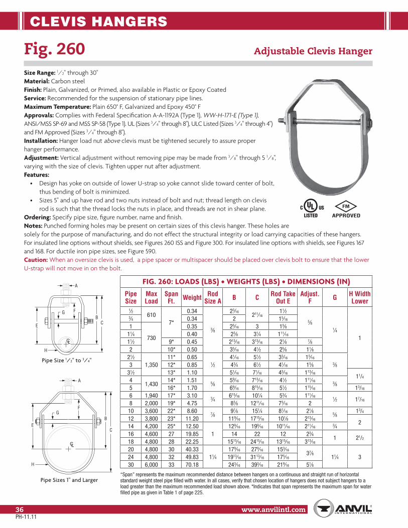
CLEVIS HANGERS
www.anvilintl.com36
FIG. 260: LOADS (LBS) • WEIGHTS (LBS) • DIMENSIONS (IN)
Pipe Size
Max Load
Span Ft. Weight Rod
Size A B C Rod Take Out E
Adjust. F G H Width
Lower1⁄2
6107*
0.34
3⁄8
23⁄16211⁄16
11⁄2
5⁄81⁄4
1
3⁄4 0.34 2 15⁄16
1
730
0.35 25⁄16 3 15⁄811⁄4 0.40 23⁄8 31⁄4 111⁄16
11⁄2 9* 0.45 213⁄16 313⁄16 21⁄8 7⁄82 10* 0.50 35⁄16 41⁄2 25⁄8 11⁄8
21⁄21,350
11* 0.651⁄2
41⁄16 51⁄2 33⁄16 15⁄16
3⁄83 12* 0.85 43⁄4 61⁄2 41⁄16 15⁄831⁄2 13* 1.10 51⁄16 71⁄16 43⁄16 113⁄16
11/44
1,43014* 1.51 5⁄8
59⁄16 713⁄16 41⁄2 111⁄16 3⁄85 16* 1.70 69⁄16 815⁄16 51⁄2 115⁄16 13/16
6 1,940 17* 3.10 3⁄4615⁄16 101⁄4 53⁄4 111⁄16 1⁄2 17/16
8 2,000 19* 4.75 83⁄8 1211⁄16 73⁄16 210 3,600 22* 8.60 7⁄8
97⁄8 151⁄4 87⁄16 21⁄8 5⁄813/4
12 3,800 23* 11.20 119⁄16 1715⁄16 101⁄8 213⁄162
14 4,200 25* 12.501
129⁄16 199⁄16 1011⁄16 211⁄16 3⁄416 4,600 27 19.85 14 22 12 23⁄4
1 21/218 4,800 28 22.25 1515⁄16 2415⁄16 1315⁄16 313⁄16
20 4,800 30 40.3311⁄4
179⁄16 279⁄16 153⁄1637⁄8
11⁄4 324 4,800 32 49.83 1913⁄16 3113⁄16 175⁄16
30 6,000 33 70.18 243⁄16 393⁄16 219⁄16 51⁄8
“Span” represents the maximum recommended distance between hangers on a continuous and straight run of horizontal standard weight steel pipe filled with water. In all cases, verify that chosen location of hangers does not subject hangers to a load greater than the maximum recommended load shown above. *Indicates that span represents the maximum span for water filled pipe as given in Table 1 of page 225.
A
C
BG
E
F
CL
H
A
CB
G
E
F
CL
H
Fig. 260 Adjustable Clevis Hanger
Size Range: 1⁄2" through 30"Material: Carbon steelFinish: Plain, Galvanized, or Primed, also available in Plastic or Epoxy CoatedService: Recommended for the suspension of stationary pipe lines.Maximum Temperature: Plain 650° F, Galvanized and Epoxy 450° FApprovals: Complies with Federal Specification A-A-1192A (Type 1), WW-H-171-E (Type 1),ANSI/MSS SP-69 and MSS SP-58 (Type 1). UL (Sizes 3/4" through 8"), ULC Listed (Sizes 3/4" through 4")and FM Approved (Sizes 3⁄4" through 8").Installation: Hanger load nut above clevis must be tightened securely to assure properhanger performance.Adjustment: Vertical adjustment without removing pipe may be made from 3⁄8" through 5 1⁄8", varying with the size of clevis. Tighten upper nut after adjustment.Features:
• Design has yoke on outside of lower U-strap so yoke cannot slide toward center of bolt, thus bending of bolt is minimized.• Sizes 5" and up have rod and two nuts instead of bolt and nut; thread length on clevis rod is such that the thread locks the nuts in place, and threads are not in shear plane.
Ordering: Specify pipe size, figure number, name and finish.Notes: Punched forming holes may be present on certain sizes of this clevis hanger. These holes aresolely for the purpose of manufacturing, and do not effect the structural integrity or load carrying capacities of these hangers.For insulated line options without shields, see Figures 260 ISS and Figure 300. For insulated line options with shields, see Figures 167 and 168. For ductile iron pipe sizes, see Figure 590.Caution: When an oversize clevis is used, a pipe spacer or multispacer should be placed over clevis bolt to ensure that the lower U-strap will not move in on the bolt.
Pipe Size 1/2" to 3/4"
Pipe Sizes 1" and Larger
PH-11.11

CLEVIS HANGERS
www.anvilintl.com 37
Copp
er Tu
bing
Ha
nger
sPi
pe R
ings
Clev
is
Hang
ers
Stee
l Pip
eCl
amps
Sock
etCl
amps
Stru
ctura
lAt
tachm
ents
Brac
kets
Ceili
ng P
lates
& Fl
ange
sCo
ncre
te In
serts
& At
tachm
ents
Hang
erRo
dsRo
d At
tachm
ents
Bolts
, Nut
s,Pi
ns &
U-B
olts
Beam
Clam
psPi
ctoria
lTa
ble o
f Con
tents
CPVC
Pipe
Han
gers
Gene
ral
Notes
FIG. 260 ISS SIZING TABLECopperTubeSize
Insulation Thickness1/2" 3/4" 1" 11/2" 2"
(Size Number)3/8 2 2 3 — —1/2 2 2 3 — —5/8 2 2 3 — —3/4 2 2 3 — —1 2 3 3 — —
11/4 3 3 3 — —11/2 3 3 4 — —2 4 4 4 — —
21/2 4 5 5 6 —3 5 5 5 6 8
31/2 5 5 6 8 84 6 6 8 8 85 8 8 8 8 106 8 10 10 10 108 10 10 12 12 12
FIG. 260 ISS SIZING TABLE
PipeSize
Insulation Thickness1/2" 3/4" 1" 11/2" 2"
(Size Number)1/2 2 2 3 — —3/4 2 3 3 — —1 2 3 3 — —
11/2 3 4 4 — —2 4 4 5 — —
21/2 5 5 5 6 83 5 5 5 6 8
31/2 5 6 6 8 84 6 6 8 8 85 8 8 8 10 106 10 10 10 10 108 12 12 12 12 12
10 14 14 14 14 1612 16 16 16 16 —
Fig. 260 ISS Clevis Hanger with Insulation Saddle System
Size Range: 1/2" through 12" pipe and accommodates up to 2" of insulation.Material: Carbon steel with high impact glass reinforced polypropylene saddle andcarbon steel pipe spacer.Finish: Plain or Galvanized Clevis HangerService: Recommended for the suspension of stationary insulated chilled or hotwater pipe lines.Maximum Temperature: 40° F to 200˚ FApprovals: Dual Fire Ratings, UL E94 VO and ASTM E84 Class 1 25/60.Installation: Hanger load nut above clevis must be tightened securely to assureproper performance. Position the pipe on the saddle. Notch insulation to fit aroundthe saddle. Square cut adjoining insulation and butt the insulation ends to eachother. Insulation joint is coated, caulked and taped following standard insulationpractice used on flanges and valves.Adjustment: Vertical adjustment without removing the hanger may be made 7/8"through 23/8" varying with the size of the clevis. Tighten all nuts after adjustment.Features: V-Block design cradles pipethrough out the entire erection process.Clevis bolt spacer included as standardkeeps the clevis lower strap from collapsing. Eliminates:
• Wood blocks and standard shields • Costly calcium silicate inserts • Re-leveling of piping at each individual hanger after insulation is completed.
Ordering: Specify size number, pipe size,insulation thickness, figure number nameand finish.
FIG. 260 ISS: LOADS (LBS) • WEIGHTS (LBS) • DIMENSIONS (IN)
260 ISS Size Number
*MaxLoad Weight Rod Size
A C **Rod Take Out E
Adjust.F G X
2550
0.73 3/8 41/2 25/8 7/8 1/4 23/8
3 1.32 1/2 61/2 41/16 17/16
3/8
35/8
4 1.83 5/8713/16 41/2 11/2 41/2
5750
2.44 815/16 51/2 13/4 511/16
6 3.81 3/4101/4 53/4 11/2 1/2
611/16
81100
5.60 1211/16 73/16 13/4 813/16
10 9.73 7/8151/4 87/16 17/8 5/8
103/4
121700
13.80 1715/16 101/8 29/16 127/16
14 15.601
199/16 1011/16 21/2 3/4 147/16
16 26.81 22 12 23/8 1 165/16
* Max load exceeds dead weight load requirement of pipe at max span, except 14 and 16 where max load is based on industry standard spacing of 14. Further information on typical pipe spans and piping weight per length can be found on pages 225 and 227, respectively.** Based on maximum insulation thickness, variations due to pipe size and insulation thickness may occur.
2" through 16"Patent #7,281,689
PH-11.11

CLEVIS HANGERS
www.anvilintl.com38
Fig. 260 ISS Clevis Hanger with Insulation Saddle System (cont.)
Application: Anvil's insulation saddle system clevises are fully tested and rated for a temperature range from 40˚F to 200˚F. Ideal for the sus-pension of stationary insulated chilled or hot water pipelines.Chilled Water Testing: Extensive field-testing and inspection has been performed to confirm that the integrity of the insulation vapor barrier for chilled water systems are sustained with the 260 ISS.To Assure Proper Vapor Barrier: Each insulation joint should be properly coated, caulked and taped. Applying standard insulation practice that is used on flanges and valves.Features: The Anvil 260 (ISS) Insulation Saddle System reduces your overall installation time and greatly simplifies the way you insulate copper and steel pipe systems. Contractors can support insulated pipe with less parts and labor.The revolutionary design of the 260 ISS spreads the load evenly over the lower strap of the clevis. The innovative V-Block design cradles the pipe at the design elevation throughout the erection process. The wide base V-Block design accommodates multiple pipe sizes, reducing the on-site inventory and the flexibility of pipe and insulation combinations with each size number.
ASTM & UL Fire Ratings: The 260 ISS has been independently tested by ASTM and UL for: • Flame Spread Index (FSI) • Smoke Development (SD) and drip ratingsApprovals from both agencies with the highest ratings for the type of product.
Low Thermal Conductivity: V-Block low thermal conductivity of .77 BTU-In./Sq.FT-Hr˚F
Insulation R-Values: The Figure 260 ISS polymer V-Block component has an R-value ranging from 5.0 to 8.7, depending on the hanger size. Meets or exceeds most commercial insulation R-values.
PH-11.11

CLEVIS HANGERS
www.anvilintl.com 39
Copp
er Tu
bing
Ha
nger
sPi
pe R
ings
Clev
is
Hang
ers
Stee
l Pip
eCl
amps
Sock
etCl
amps
Stru
ctura
lAt
tachm
ents
Brac
kets
Ceili
ng P
lates
& Fl
ange
sCo
ncre
te In
serts
& At
tachm
ents
Hang
erRo
dsRo
d At
tachm
ents
Bolts
, Nut
s,Pi
ns &
U-B
olts
Beam
Clam
psPi
ctoria
lTa
ble o
f Con
tents
CPVC
Pipe
Han
gers
Gene
ral
Notes
Fig. 260 ISS Clevis Hanger with Insulation Saddle System (cont.)
Easy InstallationMake sure the double hex nuts installed with the upper hanger load nut above the clevis are tightened securely. Position pipe on saddle.
Notch
STEP 1 STEP 2
STEP 3
Square Cut
STEP 4
Cope or notch insulation to fit around saddle. The notch should be deep enough to extend 1/8" to 1/4" beyond the saddle.
Slide the notched insulation section over saddle.
Square cut adjoining insulation and butt the insulation ends to each other.
Caulk joints and finish taping.To assure proper vapor barrier: Each insulation joint should be properly coated, caulked and taped. Applying standard insulation practice that is used on flanges and valves.Finish via standard taping method.
For chilled systems a mastic for thermal insulations or similar sealant is typically used:
Systems (50˚F or greater) apply sealant to: • The coped and flat edges of the mating insulation sections. • The V-Block saddle at the insulation interface.
Systems (Below 50˚F) apply sealant as per 50 Degrees with additional sealant to: • The V-Block saddle joint between the two saddle halves.
Additional sealant applied to V-Block saddle joint between the two saddle halves. (Chilled water below 50˚F)
Mastic applied to V-Block saddle at insulation interface. (50˚F or greater)
PH-11.11
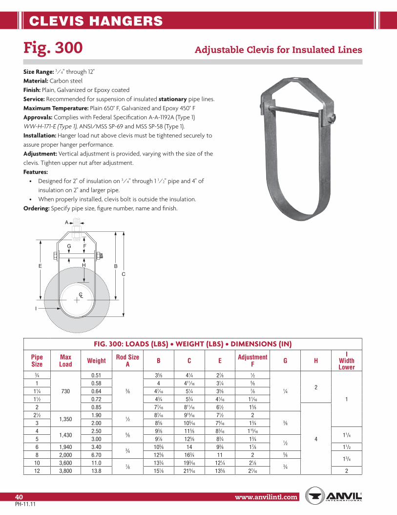
CLEVIS HANGERS
www.anvilintl.com40
Fig. 300 Adjustable Clevis for Insulated Lines
Size Range: 3⁄4" through 12"Material: Carbon steelFinish: Plain, Galvanized or Epoxy coatedService: Recommended for suspension of insulated stationary pipe lines.Maximum Temperature: Plain 650° F, Galvanized and Epoxy 450° FApprovals: Complies with Federal Specification A-A-1192A (Type 1) WW-H-171-E (Type 1), ANSI/MSS SP-69 and MSS SP-58 (Type 1).Installation: Hanger load nut above clevis must be tightened securely to assure proper hanger performance.Adjustment: Vertical adjustment is provided, varying with the size of the clevis. Tighten upper nut after adjustment.Features:
• Designed for 2" of insulation on 3⁄4" through 1 1⁄2" pipe and 4" of insulation on 2" and larger pipe.• When properly installed, clevis bolt is outside the insulation.
Ordering: Specify pipe size, figure number, name and finish.
FIG. 300: LOADS (LBS) • WEIGHT (LBS) • DIMENSIONS (IN)
PipeSize
MaxLoad Weight Rod Size
A B C E AdjustmentF G H
IWidth Lower
3⁄4
730
0.51
3⁄8
35⁄8 41⁄4 27⁄8 1⁄2
1⁄42
1
1 0.58 4 411⁄16 31⁄4 5⁄811⁄4 0.64 47⁄16 51⁄4 35⁄8 7⁄811⁄2 0.72 43⁄4 53⁄4 41⁄16 11⁄16
2 0.85 77⁄16 811⁄16 61⁄2 15⁄8
4
21⁄21,350
1.901⁄2
87⁄16 915⁄16 71⁄2 23⁄83 2.00 85⁄8 105⁄16 79⁄16 13⁄4
41,430
2.505⁄8
93⁄8 115⁄8 83⁄16 115⁄1611/4
5 3.00 97⁄8 125⁄8 83⁄4 13⁄41⁄2
6 1,940 3.403⁄4
105⁄8 14 93⁄8 17⁄8 11/2
8 2,000 6.70 123⁄8 163⁄4 11 2 5⁄813/4
10 3,600 11.07⁄8
133⁄4 193⁄16 121⁄4 21⁄83⁄4
12 3,800 13.8 151⁄8 219⁄16 135⁄8 27⁄16 2
A
F
C
G
H BE
CL
I
PH-11.11

CLEVIS HANGERS
www.anvilintl.com 41
Copp
er Tu
bing
Ha
nger
sPi
pe R
ings
Clev
is
Hang
ers
Stee
l Pip
eCl
amps
Sock
etCl
amps
Stru
ctura
lAt
tachm
ents
Brac
kets
Ceili
ng P
lates
& Fl
ange
sCo
ncre
te In
serts
& At
tachm
ents
Hang
erRo
dsRo
d At
tachm
ents
Bolts
, Nut
s,Pi
ns &
U-B
olts
Beam
Clam
psPi
ctoria
lTa
ble o
f Con
tents
CPVC
Pipe
Han
gers
Gene
ral
Notes
Fig. 590 Adjustable Clevis for Ductile or Cast Iron Pipe
Size Range: 4" through 24" ductile or cast iron pipeMaterial: Carbon steelFinish: Plain or GalvanizedService: Recommended for the suspension of stationary ductile iron or cast iron pipe.Approvals: Complies with Federal Specification A-A-1192A (Type 1) WW-H-171-E (Type 1), ANSI/MSS SP-69 and MSS SP-58 (Type 1).Installation: Hanger rod nut above clevis must be tightened securely to assure proper hanger performance.Adjustment: Vertical adjustment without removing pipe may be made from 1 15⁄16" through 3 3⁄16", varying with the size of the clevis. Tighten upper nut after adjustment.Ordering: Specify pipe size, figure number, name and finish.Note: Figure 590 sizes 12" and below typically feature a Figure 260 Top Component.
FIG. 590: LOADS (LBS) • WEIGHT (LBS) • DIMENSIONS (IN)
D.I./C.I. Pipe Size
MaxLoad Weight D.I./C.I.
Pipe O.D.Rod Size
A B C E F G WidthLower
3 1,350 1.10 3.96 1⁄2 51⁄16 71⁄16 43⁄16 113⁄16
11/4
4 1,430 1.64 4.80 5⁄8 53⁄4 83⁄16 43⁄4
115⁄16
6 1,940 4.26 6.903⁄4
71⁄8 109⁄16 515⁄16 11/2
8 2,000 6.70 9.05 85⁄8 133⁄16 71⁄2 21⁄413/4
10 3,600 9.73 11.107⁄8
101⁄8 1511⁄16 83⁄4 25⁄16
12 3,800 13.64 13.20 121⁄16 1811⁄16 1011⁄16 27⁄82
14 4,200 16.04 15.30
1
131⁄4 207⁄8 115⁄16 29⁄16
16 4,600 24.52 17.40 141⁄4 2215⁄16 129⁄16 27⁄16
21/2
18 4,800 27.45 19.50 167⁄8 265⁄8 153⁄16
313⁄1620 4,800 46.24 21.6011⁄4
181⁄4 291⁄16 163⁄83
24 4,800 57.10 25.80 205⁄16 331⁄4 183⁄8
CBE
F
A
CL
G
PH-11.11
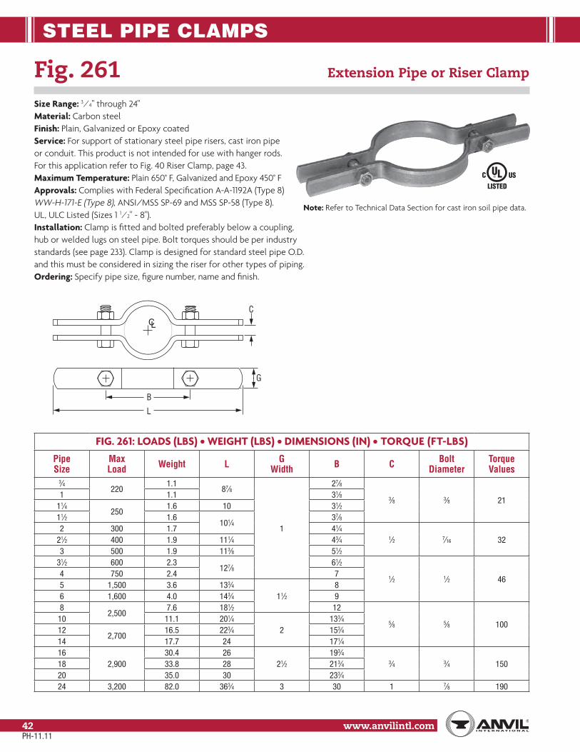
STEEL PIPE CLAMPS
www.anvilintl.com42
Fig. 261 Extension Pipe or Riser Clamp
Size Range: 3⁄4" through 24"Material: Carbon steelFinish: Plain, Galvanized or Epoxy coatedService: For support of stationary steel pipe risers, cast iron pipeor conduit. This product is not intended for use with hanger rods.For this application refer to Fig. 40 Riser Clamp, page 43.Maximum Temperature: Plain 650° F, Galvanized and Epoxy 450° FApprovals: Complies with Federal Specification A-A-1192A (Type 8) WW-H-171-E (Type 8), ANSI/MSS SP-69 and MSS SP-58 (Type 8). UL, ULC Listed (Sizes 1 1⁄2" - 8").Installation: Clamp is fitted and bolted preferably below a coupling,hub or welded lugs on steel pipe. Bolt torques should be per industrystandards (see page 233). Clamp is designed for standard steel pipe O.D.and this must be considered in sizing the riser for other types of piping.Ordering: Specify pipe size, figure number, name and finish.
FIG. 261: LOADS (LBS) • WEIGHT (LBS) • DIMENSIONS (IN) • TORQUE (FT-LBS)
PipeSize
MaxLoad Weight L G
Width B C Bolt Diameter
TorqueValues
3⁄4220
1.187⁄8
1
27⁄8
3⁄8 3⁄8 211 1.1 31⁄8
11⁄4250
1.6 10 31⁄211⁄2 1.6
101⁄437⁄8
2 300 1.7 41⁄41⁄2 7⁄16 3221⁄2 400 1.9 111⁄4 43⁄4
3 500 1.9 113⁄8 51⁄231⁄2 600 2.3
127⁄861⁄2
1⁄2 1⁄2 464 750 2.4 75 1,500 3.6 133⁄4
11⁄28
6 1,600 4.0 143⁄4 98
2,5007.6 181⁄2 12
5⁄8 5⁄8 10010 11.1 201⁄4
2133⁄4
122,700
16.5 223⁄4 153⁄414 17.7 24 171⁄416
2,90030.4 26
21⁄2193⁄4
3⁄4 3⁄4 15018 33.8 28 213⁄420 35.0 30 233⁄424 3,200 82.0 363⁄4 3 30 1 7⁄8 190
L
B
C
G
CL
Note: Refer to Technical Data Section for cast iron soil pipe data.
PH-11.11

STEEL PIPE CLAMPS
www.anvilintl.com 43
Copp
er Tu
bing
Ha
nger
sPi
pe R
ings
Clev
is Ha
nger
sSt
eel P
ipe
Clam
psSo
cket
Clam
psSt
ructu
ral
Attac
hmen
tsBr
acke
tsCe
iling
Plat
es&
Flan
ges
Conc
rete
Inse
rts&
Attac
hmen
tsHa
nger
Rods
Rod
Attac
hmen
tsBo
lts, N
uts,
Pins
& U
-Bol
tsBe
amCl
amps
Picto
rial
Tabl
e of C
onten
tsCP
VCPi
pe H
ange
rsGe
nera
lNo
tes
Fig. 40 Riser Clamp – Standard
Size Range: 2" through 24"Material: Carbon steel (CS), Alloy (A), or Stainless Steel (SS)Finish: Plain or GalvanizedMaximum Temperature: Galvanized 450° F, 650° F (CS), 950° F (A) and 1,000° F (SS)Service: Riser clamps are used for the support of vertical piping. Load is carried by shear lugs which are welded to the pipe. Shear lugs provided upon request. Local pipe wall stress evaluation available upon request.Approvals: Complies with Federal Specification A-A-1192A (Type 42),ANSI/MSS SP-69 and MSS SP-58 (Type 42).Ordering: Specify pipe size, material, figure number, name and finish.Note: If different loads or dimensions are required, refer to Fig. 40 SDspecial design riser clamp.
FIG. 40: LOADS (LBS) • WEIGHT (LBS) • DIMENSIONS (IN)
Pipe Size
Max LoadC-C E F
(max)G
(max) S A (CS)
A (alloy) (SS)
B (max)
Maximum Weight Each
Rigid Assembly
Spring Assembly CS SS Alloy
2900 1,800
18 91⁄2 21/2 3⁄4 11⁄4
7⁄8
2
18 15 1821⁄2
20 1020 20 20
3 1,500 3,000 5⁄83
111⁄2
30 25 304
2,200 4,400 22 11 3⁄4 11⁄4 11⁄840 40 44
54
2 45 40 456
3,000 6,00024 12
7⁄8 11⁄2 7⁄8 11⁄460 60 73
8 27 131⁄2 5 82 82 8210 5,500 11,000 30 15 11⁄4 6 21⁄4 11⁄4 15⁄8
3
157 157 15712
7,800 15,60032 16
11⁄27
21⁄213⁄8
17⁄8 216 202 25014 34 17 13⁄8 228 228 26316
9,000 18,00036 18 6
11⁄2 2314 277 315
18 39 191⁄2 7 338 338 37720
13,500 27,00042 21
2 8 31⁄2 25⁄8 25⁄8 41⁄4525 525 580
24 45 221⁄2 621 565 681
Fig. 140, 146
Field WeldedShear Lugs
Fig. 290
Fig. 40
For Shear Lug Dimensions, refer to Special Design Products Fig. 40SD.
PIPESPACER
Sizes 16" to 20" have (4) inner bolts.
BOLT/STUD DIA. F
EEC to C
B
A
S
G (max)
CL
PH-11.11

STEEL PIPE CLAMPS
www.anvilintl.com44
Fig. 103 Offset Pipe Clamp
Size Range: 3⁄4" through 8"Material: Carbon steelFinish: Plain or GalvanizedService: For use in supporting piping away from wall or floor.Maximum Temperature: Plain 650° F, Galvanized 450° FOrdering: Specify pipe size, figure number, name and finishService: For use in supporting horizontal piping away from the wall or floor (not to be used as a riser type support)
FIG. 103: LOADS (LBS) • WEIGHT (LBS) • DIMENSIONS (IN)PipeSize
MaxLoad Weight W B D Bolt Dia.
FG
Width3⁄4
190
1.50 83⁄4 21⁄27⁄16 3⁄8
11/4
1 1.60 91⁄4 25⁄811⁄4 1.70 93⁄4 213⁄16
11⁄2 1.80 10 215⁄16
2420
2.70 111⁄4 33⁄16
9⁄16 1⁄221⁄2 2.90 113⁄4 37⁄16
3 3.20 127⁄8 33⁄44 610 4.60 137⁄8 41⁄4 11/2
5 7.30 155⁄8 43⁄411⁄16 5⁄8 26 870 7.80 163⁄4 55⁄16
8 9.00 183⁄4 65⁄16
B
Bolt Dia. F
W
LOAD
HOLE SIZED
CL
G
Fig. 100 Extended Pipe Clamp
Size Range: 1⁄2" through 8"Material: Carbon steelFinish: Plain or GalvanizedService: For attachment to structure without use of rods.Maximum Temperature: Plain 650° F, Galvanized 450° FOrdering: Specify pipe size, figure number, name and finish.
FIG. 100: WEIGHT (LBS) • DIMENSIONS (IN)PipeSize W E F G
Width H Weight1⁄2 55⁄8 27⁄8
3⁄8
1 41⁄4 1.853⁄4 57⁄8 31⁄8
11⁄4
41⁄2 2.201 63⁄8 35⁄8 5 2.25
11⁄4 67⁄8 41⁄8 51⁄2 2.3411⁄2 71⁄8 43⁄8 53⁄4 2.392 83⁄8 51⁄8
1⁄2
67⁄8 3.2521⁄2 87⁄8 55⁄8 73⁄8 3.403 10 63⁄4 81⁄4 3.584 105⁄8 73⁄8 11⁄2 91⁄8 4.745 123⁄8 85⁄8
5⁄8 2107⁄8 5.09
6 131⁄2 93⁄4 12 8.238 151⁄2 113⁄4 14 9.25
1⁄8"
E
F
G
12"W
H
CL
PH-11.11

STEEL PIPE CLAMPS
www.anvilintl.com 45
Copp
er Tu
bing
Ha
nger
sPi
pe R
ings
Clev
is Ha
nger
sSt
eel P
ipe
Clam
psSo
cket
Clam
psSt
ructu
ral
Attac
hmen
tsBr
acke
tsCe
iling
Plat
es&
Flan
ges
Conc
rete
Inse
rts&
Attac
hmen
tsHa
nger
Rods
Rod
Attac
hmen
tsBo
lts, N
uts,
Pins
& U
-Bol
tsBe
amCl
amps
Picto
rial
Tabl
e of C
onten
tsCP
VCPi
pe H
ange
rsGe
nera
lNo
tes
Fig. 212 Medium Pipe Clamp
Size Range: 1⁄2" through 30"Material: Carbon steelFinish: Plain or GalvanizedService: Recommended for suspension of cold pipe lines or hot lines where no insulation is required.Maximum Temperature: Plain 750° F, Galvanized 450° FApprovals: Complies with Federal Specification A-A-1192A (Type 4) WW-H-171-E (Type 4), ANSI/MSS SP-69 and MSS SP-58 (Type 4). UL, ULC Listed and FM Approved (Sizes 3⁄4" - 8").Installation: Normally used with weldless eye nut Fig. 290, page 97 or eye rod.Features:
• Clamps tightly to pipe.• Wide range of sizes.• Equal gap design on many sizes.
Ordering: Specify pipe size, figure number, name and finish.Note: The “C” gap dimension ensures adequateclearance at the top attachment point for a weldlesseye nut or other appropriate rod attachment. Thisgap may or may not be present on the bottom portion of the clamp. If different loads or dimensions are required,refer to Fig. 42 SD non-standard two bolt pipe clamp.
D
H
B
E
FC
CL
G
FIG. 212: LOADS (LBS) • WEIGHT (LBS) • DIMENSIONS (IN)
Pipe Size
Span Ft.
Max Load For Service Temp Weight B C
Rod Take Out
EH D F G
Width650° F 750° F
1⁄2
7* 500–
0.29 1
1⁄2
13⁄16 117⁄32 123⁄32
5⁄16
1
3⁄4 0.3311⁄8
11⁄4121⁄32
125⁄32
1 0.35 13⁄8 129⁄32
11⁄4 0.38 17⁄16 15⁄8 131⁄32 25⁄32
11⁄2 9* 800 0.43 19⁄16 111⁄16 23⁄32 27⁄32
2 10*
1,040 930
1.10 21⁄8 21⁄8 23⁄4 23⁄4
1⁄221⁄2 11* 1.20 25⁄8
5⁄8
25⁄8 31⁄4 31⁄43 12* 1.40 27⁄8 27⁄8 31⁄2 31⁄2
31⁄2 13* 1.50 33⁄16 33⁄16 313⁄16 313⁄16
4 14* 1.80 31⁄2 31⁄2 41⁄4 41⁄45 16* 2.60 43⁄16 3⁄4 43⁄16 415⁄16 415⁄16 5⁄8 11/4
6 17*1,615 1,440
5.40 47⁄811⁄4
47⁄8 53⁄4 53⁄4 3⁄4 11/28 19* 6.50 6 6 67⁄8 67⁄810 22*
2,490 2,220
13.60 77⁄161
77⁄16 89⁄16 89⁄16
7⁄8 2
12 23* 15.20 87⁄16 87⁄16 99⁄16 99⁄16
14 20 20.50 91⁄411⁄8
91⁄4 105⁄8 105⁄8
21/216 15 22.30 101⁄4 101⁄4 115⁄8 115⁄818 15
3,060 2,73031.60 115⁄8 11⁄4 115⁄8 13 13 1
20 12 35.80 123⁄4 13⁄8 123⁄4 141⁄8 141⁄8 11⁄824 12 53.10 151⁄4 15⁄8 151⁄4 167⁄8 167⁄8 11⁄4 330 9 3,500 3,360 113.90 19 2 19 211⁄8 211⁄8 13⁄4 4
Clamps may be furnished with square ends. “Span” represents the maximum recommended distance between hangers on a continuous & straight run of horizontal standard weight steel pipe filled with water. In all cases, verify that chosen location of hangers does not subject hangers to a load greater than the maximum recommended load shown above. For vapor service, the presence of fittings or insulation, and other weights and types of pipe, spans may either increase or decrease. In all cases, verify that chosen location of hanger does not subject hangers to a load greater than the maximum recommended load shown. *Indicates that span represents the maximum span for water filled pipe as given in Table 1 of page 225.
Note: This picture is representative of a typical Figure 212. Distance between clamp ears beneath pipe may or may not be equal to upper gap.
PH-11.11

STEEL PIPE CLAMPS
www.anvilintl.com46
Fig. 212FP Earthquake Bracing Clamp
Size Range: 2 1⁄2" through 12"Material: Carbon steelFinish: Plain or GalvanizedService: For seismic bracing, to be used with Fig. 113 brace fitting. Pipe clamp bolt holes are designed to match holes in brace fitting.Maximum Temperature: Plain 750° F, Galvanized 450° FApprovals: Complies with Federal Specification A-A-1192A (Type 4) WW-H-171-E (Type 4), ANSI/MSS SP-69 and MSS SP-58 (Type 4).Installation: Designed for use with Fig. 113 brace fitting, see page 71.Ordering: Specify pipe size, figure number, name and finish.Note: The “C” gap dimension should be used at the upper and lower locations to ensure proper installation of the clamp. Standard Figure 212 will be furnished for sizes 2 1⁄2" thru 4".
FIG. 212FP: LOADS (LBS) • WEIGHT (LBS) • DIMENSIONS (IN)
Pipe SizeMax Load
For Service Temp Weight (lbs) B C Rod Take
Out E H D F GWidth
650° F 750° F21⁄2
1,040 930
1.20 25⁄8
5⁄8
25⁄8 31⁄4 31⁄4
1⁄2
13 1.40 27⁄8 27⁄8 31⁄2 31⁄2
31⁄2 1.50 33⁄16 33⁄16 313⁄16 313⁄16
4 1.80 31⁄2 31⁄2 41⁄4 41⁄4
5 2.50 43⁄16 3⁄4 43⁄16 415⁄16 415⁄16 11/4
6 5.20 47⁄811⁄4
47⁄8 53⁄4 53⁄411/2
8 6.30 6 6 67⁄8 67⁄8
10 13.60 77⁄161
77⁄16 89⁄16 89⁄16 2
12 15.20 87⁄16 87⁄16 99⁄16 99⁄16
D
HB
EF
C
CL
G
PH-11.11
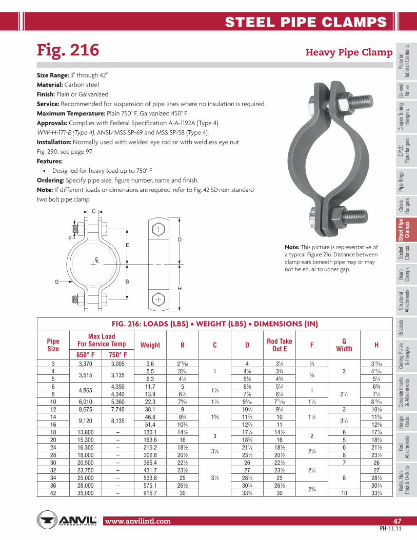
STEEL PIPE CLAMPS
www.anvilintl.com 47
Copp
er Tu
bing
Ha
nger
sPi
pe R
ings
Clev
is Ha
nger
sSt
eel P
ipe
Clam
psSo
cket
Clam
psSt
ructu
ral
Attac
hmen
tsBr
acke
tsCe
iling
Plat
es&
Flan
ges
Conc
rete
Inse
rts&
Attac
hmen
tsHa
nger
Rods
Rod
Attac
hmen
tsBo
lts, N
uts,
Pins
& U
-Bol
tsBe
amCl
amps
Picto
rial
Tabl
e of C
onten
tsCP
VCPi
pe H
ange
rsGe
nera
lNo
tes
Fig. 216 Heavy Pipe Clamp
Size Range: 3" through 42"Material: Carbon steelFinish: Plain or GalvanizedService: Recommended for suspension of pipe lines where no insulation is required.Maximum Temperature: Plain 750° F, Galvanized 450° FApprovals: Complies with Federal Specification A-A-1192A (Type 4) WW-H-171-E (Type 4), ANSI/MSS SP-69 and MSS SP-58 (Type 4).Installation: Normally used with welded eye rod or with weldless eye nut Fig. 290, see page 97.Features:
• Designed for heavy load up to 750° FOrdering: Specify pipe size, figure number, name and finish.Note: If different loads or dimensions are required, refer to Fig. 42 SD non-standardtwo bolt pipe clamp.
FIG. 216: LOADS (LBS) • WEIGHT (LBS) • DIMENSIONS (IN)
PipeSize
Max Load For Service Temp Weight B C D Rod Take
Out E F GWidth H
650° F 750° F3 3,370 3,005 3.6 215⁄16
14 31⁄8 3⁄4
2313⁄16
43,515 3,135
5.5 39⁄16 47⁄8 33⁄4 7⁄8411⁄16
5 6.3 41⁄8 51⁄2 43⁄8 51⁄46
4,8654,350 11.7 5
11⁄865⁄8 51⁄4
121/2
63⁄88 4,340 13.9 61⁄8 75⁄8 61⁄4 71⁄2
10 6,010 5,360 22.3 79⁄16 11⁄4 91⁄16 711⁄16 11⁄4 815⁄16
12 8,675 7,740 38.1 915⁄8
107⁄8 91⁄411⁄2
3 105⁄814
9,120 8,13546.8 93⁄4 117⁄8 10
31/2115⁄8
16 51.4 103⁄4 127⁄8 11 125⁄818 13,800 – 130.1 141⁄2
3171⁄4 141⁄2
26 171⁄4
20 15,300 – 163.6 16 183⁄4 16 5 183⁄424 16,300 – 215.2 181⁄2
31⁄4211⁄2 181⁄2
21⁄46 211⁄2
28 18,000 – 302.8 201⁄2 231⁄2 201⁄2 8 231⁄230 20,500 – 365.4 221⁄2
31⁄2
26 221⁄221⁄2
7 2632 23,750 – 431.7 231⁄2 27 231⁄2
827
34 25,000 – 533.8 25 281⁄2 25 281⁄236 28,000 – 575.1 261⁄2 301⁄4 261⁄2
23⁄4301⁄4
42 35,000 – 915.7 30 333⁄4 30 10 333⁄4
D
HB
EF
C
CL
G
Note: This picture is representative of a typical Figure 216. Distance between clamp ears beneath pipe may or may not be equal to upper gap.
PH-11.11

STEEL PIPE CLAMPS
www.anvilintl.com48
Fig. 295 Double Bolt Pipe Clamp
Size Range: 3⁄4" through 36"Material: Carbon steelFinish: Plain or GalvanizedService: Recommended for suspension of pipe requiringinsulation within the limitation of temperature and loadsshown below.Maximum Temperature: Plain 750° F, Galvanized 450° FApprovals: Complies with Federal Specification A-A-1192A(Type 3), WW-H-171-E (Type 3), ANSI/MSS SP-69 andMSS SP-58 (Type 3).Installation: Attachment to the clamp may be madewith a welded eye rod Fig. 278, page 93 or the weldlesseye nut Fig. 290, see page 97.Features:
• Sizes 6" and above accommodate up to 4" thick insulation.• Figure 41SD will accommodate larger insulation thicknesses, loads and dimensions.
Ordering: Specify pipe size, figure number, name and finish.
D
HB
E
F
C
CL
G
FIG. 295: LOADS (LBS) • WEIGHT (LBS) • DIMENSIONS (IN)
Pipe Size
Max Span Ft.
Max Load For Service Temp. Weight B C D Rod Take
Out E F GWidth H
650° F 750° F3⁄4
7* 950– 0.7 15⁄16
5⁄827⁄8 27⁄16
3⁄8 113⁄8
1 – 0.8 11⁄16 3 29⁄16 11⁄211⁄4 – 0.8 11⁄4 31⁄8 211⁄16 111⁄16
11⁄2 9*
1,545 1,380
2.3 113⁄1611⁄16
47⁄8 41⁄8 5⁄8 11/423⁄8
2 10* 2.6 21⁄8 57⁄8 51⁄8 211⁄16
21⁄2 11* 1.97 25⁄8 5⁄86 53⁄8 1⁄2 1
31⁄43 12* 2.17 27⁄8 65⁄8 6 31⁄24 14*
2,500 2,2306.7 33⁄8
11⁄1675⁄8 61⁄2
3⁄42
41⁄25 16* 7.0 315⁄16 81⁄8 7 56 17*
2,865 2,5557.31 47⁄8
11⁄493⁄8 81⁄2
11/253⁄4
8 19* 8.33 6 103⁄8 91⁄2 67⁄810 22*
3,240 2,89019.8 67⁄8
17⁄1612 107⁄16
1 21/281⁄4
12 23" 22.3 77⁄8 13 117⁄16 91⁄414 20
4,300 3,83537.7 91⁄16
2
145⁄16 1211⁄16
11⁄43
1011⁄16
1615
41.4 101⁄16 155⁄16 1311⁄16 1111⁄16
18 44.9 111⁄16 165⁄16 1411⁄16 1211⁄16
20 12 5,490 4,900 57.3 123⁄8 175⁄8 157⁄813⁄8
1424 12 4,500 4,015 65.9 143⁄8 195⁄8 177⁄8 1628 – 6,000 – 112.3 171⁄2 21⁄4 241⁄4 213⁄4 11⁄4 4 2030 9 7,500 – 150.0 181⁄2
21⁄2261⁄8 233⁄8 13⁄8 5 211⁄4
32 – 8,250 – 193.3 195⁄8 28 25 11⁄2 6 225⁄834 – 9,800 – 248.8 211⁄2
3311⁄4 273⁄4
13⁄4 525
36 – 10,500 – 257.5 221⁄2 321⁄4 283⁄4 26Clamps may be furnished with square ends. “Span” represents the maximum recommended distance between hangers on a continuous and straight run of horizontal standard weight steel pipe filled with water. In all cases, verify that chosen location of hangers does not subject hangers to a load greater than the maximum recommended load shown above. *Indicates that span represents the maximum span for water filled pipe as given in Table 1 of page 225. For vapor service, the presence of fittings or insulation, and other weights and types of pipe, spans may either increase or decrease. In all cases, verify that chosen location of hanger does not subject hangers to a load greater than the maximum recommended load shown.
Note: This picture is representative of a typical Figure 295. Distance between clamp ears beneath pipe may or may not be equal to upper gap.
PH-11.11
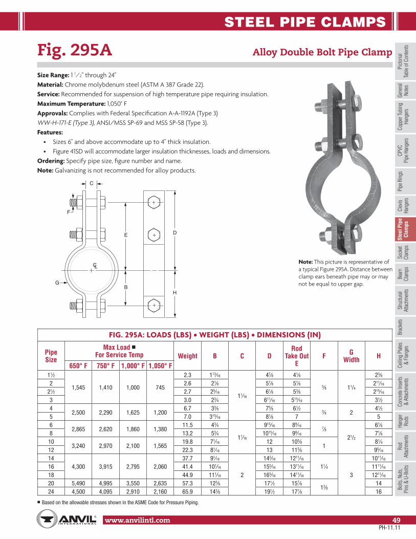
STEEL PIPE CLAMPS
www.anvilintl.com 49
Copp
er Tu
bing
Ha
nger
sPi
pe R
ings
Clev
is Ha
nger
sSt
eel P
ipe
Clam
psSo
cket
Clam
psSt
ructu
ral
Attac
hmen
tsBr
acke
tsCe
iling
Plat
es&
Flan
ges
Conc
rete
Inse
rts&
Attac
hmen
tsHa
nger
Rods
Rod
Attac
hmen
tsBo
lts, N
uts,
Pins
& U
-Bol
tsBe
amCl
amps
Picto
rial
Tabl
e of C
onten
tsCP
VCPi
pe H
ange
rsGe
nera
lNo
tes
Fig. 295A Alloy Double Bolt Pipe Clamp
Size Range: 1 1⁄2" through 24"Material: Chrome molybdenum steel (ASTM A 387 Grade 22).Service: Recommended for suspension of high temperature pipe requiring insulation.Maximum Temperature: 1,050° FApprovals: Complies with Federal Specification A-A-1192A (Type 3) WW-H-171-E (Type 3), ANSI/MSS SP-69 and MSS SP-58 (Type 3).Features:
• Sizes 6" and above accommodate up to 4" thick insulation.• Figure 41SD will accommodate larger insulation thicknesses, loads and dimensions.
Ordering: Specify pipe size, figure number and name.Note: Galvanizing is not recommended for alloy products.
FIG. 295A: LOADS (LBS) • WEIGHT (LBS) • DIMENSIONS (IN)
Pipe Size
Max Load ■ For Service Temp Weight B C D
Rod Take Out
EF G
Width H650° F 750° F 1,000° F 1,050° F
11⁄2
1,545 1,410 1,000 745
2.3 113⁄16
11⁄16
47⁄8 41⁄8
5⁄8 11/4
23⁄82 2.6 21⁄8 57⁄8 51⁄8 211⁄16
21⁄2 2.7 25⁄16 61⁄8 53⁄8 215⁄16
3 3.0 23⁄4 611⁄16 515⁄16 31⁄24
2,500 2,290 1,625 1,2006.7 33⁄8 75⁄8 61⁄2
3⁄4 241⁄2
5 7.0 315⁄16 81⁄8 7 56
2,865 2,620 1,860 1,38011.5 43⁄4
17⁄16
915⁄16 89⁄167⁄8
21/2
61⁄88 13.2 53⁄4 1015⁄16 99⁄16 71⁄8
103,240 2,970 2,100 1,565
19.8 71⁄16 12 105⁄81
81⁄412 22.3 81⁄16 13 115⁄8 95⁄16
144,300 3,915 2,795 2,060
37.7 91⁄16
2
145⁄16 1211⁄16
11⁄43
1011⁄16
16 41.4 101⁄16 155⁄16 1311⁄16 1111⁄16
18 44.9 111⁄16 165⁄16 1411⁄16 1211⁄16
20 5,490 4,995 3,550 2,635 57.3 123⁄8 171⁄2 157⁄813⁄8
1424 4,500 4,095 2,910 2,160 65.9 143⁄8 191⁄2 177⁄8 16
■ Based on the allowable stresses shown in the ASME Code for Pressure Piping.
D
HB
E
F
C
CL
G
Note: This picture is representative of a typical Figure 295A. Distance between clamp ears beneath pipe may or may not be equal to upper gap.
PH-11.11

STEEL PIPE CLAMPS
www.anvilintl.com50
Fig 295H Heavy Duty Double Bolt Pipe Clamp
Size Range: 6" through 36"Material: Carbon steelFinish: Plain or GalvanizedService: Recommended for suspension of pipe requiring insulation within the limitationof temperature and loads shown below.Maximum Temperature: Plain 750° F, Galvanized 450° FApprovals: Complies with Federal Specification A-A-1192A (Type 3) WW-H-171-E (Type 3), ANSI/MSS SP-69 and MSS SP-58 (Type 3).Features:
• Accommodates up to 4" thick insulation.• Figure 41SD will accommodate larger insulation thicknesses, loads and dimensions.
Ordering: Specify pipe size, figure number, name and finish.
FIG 295H: LOADS (LBS) • WEIGHT (LBS) • DIMENSIONS (IN)
PipeSize
Max Load For Service Temp Weight B C D Rod Take
Out E F GWidth H
650° F 750° F6 3,500 3,125 12.0 43⁄4 13⁄4 1013⁄16 815⁄16 1
21/26
8 4,800 4,285 18.5 6 2 113⁄8 101⁄8 11⁄8 71⁄410 5,500 4,910 30.3 71⁄4 21⁄4 131⁄8 113⁄8 11⁄4
31/29
12 7,000 6,250 42.0 85⁄821⁄2
145⁄16 129⁄16 13⁄8 103⁄814 9,500 8,485 60.0 95⁄8 151⁄2 131⁄2 11⁄2 4 115⁄816 10,000 8,930 80.0 107⁄8 3 171⁄8 147⁄8 13⁄4 41/2 131⁄818 13,800 12,325 115.0 121⁄2
31⁄2181⁄4 161⁄4
24 141⁄2
20 15,300 13,665 140.0 131⁄2 193⁄4 171⁄4 5 1624 16,300 14,555 190.0 151⁄2 225⁄16 195⁄16 6 181⁄228 18,000 – 354.0 187⁄8 4 313⁄4 271⁄4
21⁄47 233⁄8
30 20,500 – 406.0 197⁄841⁄4
323⁄4 281⁄48
243⁄832 23,750 – 555.0 213⁄4 36 31
21⁄2263⁄4
34 25,000 – 604.0 233⁄8 371⁄2 321⁄2 7 283⁄836 28,000 – 678.0 245⁄8 41⁄2 401⁄4 343⁄4 23⁄4 8 301⁄8
Clamps may be furnished with square ends.
D
HB
E
F
C
CL
G
Note: This picture is representative of a typical Figure 295H. Distance between clamp ears beneath pipe may or may not be equal to upper gap.
PH-11.11

STEEL PIPE CLAMPS
www.anvilintl.com 51
Copp
er Tu
bing
Ha
nger
sPi
pe R
ings
Clev
is Ha
nger
sSt
eel P
ipe
Clam
psSo
cket
Clam
psSt
ructu
ral
Attac
hmen
tsBr
acke
tsCe
iling
Plat
es&
Flan
ges
Conc
rete
Inse
rts&
Attac
hmen
tsHa
nger
Rods
Rod
Attac
hmen
tsBo
lts, N
uts,
Pins
& U
-Bol
tsBe
amCl
amps
Picto
rial
Tabl
e of C
onten
tsCP
VCPi
pe H
ange
rsGe
nera
lNo
tes
Fig. 224 Alloy Steel Pipe Clamp
Size Range: 4" through 16"Material: Chrome molybdenum steel except U-bolt which is stainless steel.Service: Recommended for suspension of high temperature pipe requiring up to 4" of insulation.Maximum Temperature: 1,050° FApprovals: Complies with Federal Specification A-A-1192A (Type 2) WW-H-171-E (Type 2), ANSI/MSS SP-69 and MSS SP-58 (Type 2).Installation: Normally used with welded eye rod Fig. 278, see page 93, or weldless eye nut Fig. 290, see page 97.Features:
• Designed for the support of loads at temperatures up to 1,050° F.• Designed to satisfy most critical engineering specifications.• Yoke has rugged cross sectional area, eliminating high stress conditions.• When used on pipe with 4" of insulation the top bolt is outside of the insulation.
Ordering: Specify pipe size, figure number and name.
FIG. 224: LOADS (LBS) • WEIGHT (LBS) • DIMENSIONS (IN)
Pipe Size
Max Load ■Weight C D
Rod Take Out
EF H K
750° F 950° F 1,000° F 1,050° F4 3,780 3,300 2,770 1,890 4.0 11⁄16 37⁄8 63⁄4 7⁄8 1⁄2 61⁄26
6,060 5,290 4,440 3,0307.5
17⁄16
57⁄16 85⁄161 5⁄8
91⁄88 9.0 611⁄16 99⁄16 111⁄810 9,060 7,910 6,640 4,420 15.8 83⁄8 107⁄8 11⁄8 3⁄4 135⁄812
12,570 10,980 9,015 6,01024.3
115⁄16
101⁄8 127⁄811⁄2 7⁄8
161⁄814 26.3 111⁄8 137⁄8 173⁄816 31.0 121⁄4 15 195⁄8
■ Based on the allowable stresses shown in the ASME Code for Pressure Piping. Over tightening of nuts may overstress U-bolts reducing the load rating. Installation tag attached to clamp gives proper nut tightening.
C
F
H
D E
KCL
PH-11.11
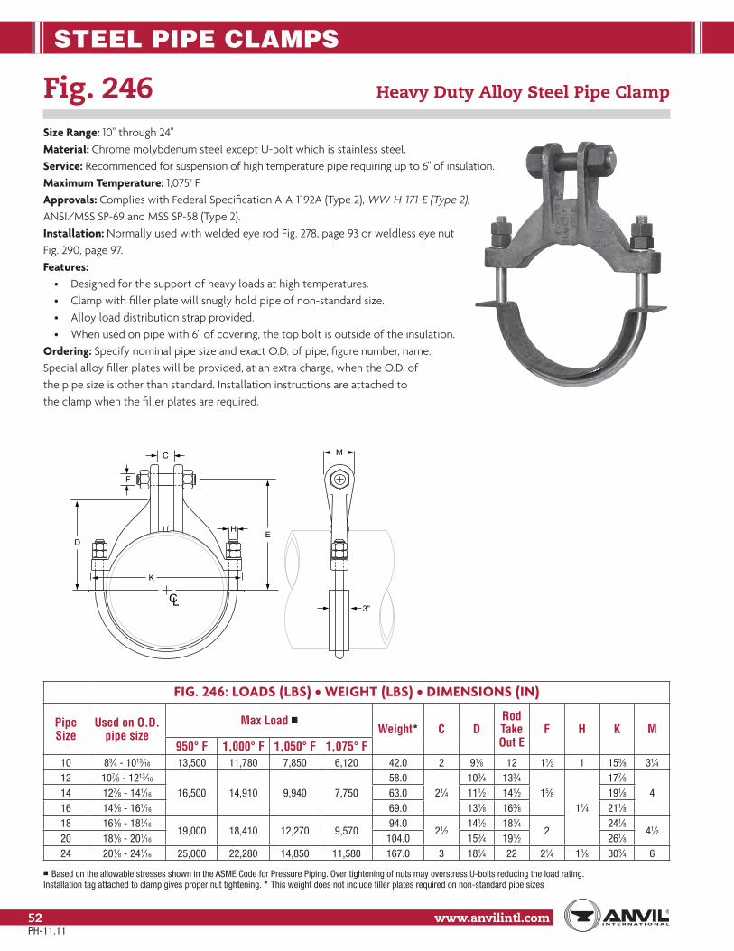
STEEL PIPE CLAMPS
www.anvilintl.com52
Fig. 246 Heavy Duty Alloy Steel Pipe Clamp
Size Range: 10" through 24"Material: Chrome molybdenum steel except U-bolt which is stainless steel.Service: Recommended for suspension of high temperature pipe requiring up to 6" of insulation.Maximum Temperature: 1,075° FApprovals: Complies with Federal Specification A-A-1192A (Type 2), WW-H-171-E (Type 2),ANSI/MSS SP-69 and MSS SP-58 (Type 2).Installation: Normally used with welded eye rod Fig. 278, page 93 or weldless eye nutFig. 290, page 97.Features:
• Designed for the support of heavy loads at high temperatures.• Clamp with filler plate will snugly hold pipe of non-standard size.• Alloy load distribution strap provided.• When used on pipe with 6" of covering, the top bolt is outside of the insulation.
Ordering: Specify nominal pipe size and exact O.D. of pipe, figure number, name.Special alloy filler plates will be provided, at an extra charge, when the O.D. ofthe pipe size is other than standard. Installation instructions are attached tothe clamp when the filler plates are required.
FIG. 246: LOADS (LBS) • WEIGHT (LBS) • DIMENSIONS (IN)
Pipe Size
Used on O.D. pipe size
Max Load ■Weight* C D
Rod Take Out E
F H K M950° F 1,000° F 1,050° F 1,075° F
10 83⁄4 - 1013⁄16 13,500 11,780 7,850 6,120 42.0 2 91⁄8 12 11⁄2 1 153⁄8 31⁄412 107⁄8 - 1213⁄16
16,500 14,910 9,940 7,75058.0
21⁄4103⁄4 133⁄4
15⁄811⁄4
177⁄8414 127⁄8 - 141⁄16 63.0 111⁄2 141⁄2 191⁄8
16 141⁄8 - 161⁄16 69.0 131⁄8 163⁄8 211⁄818 161⁄8 - 181⁄16
19,000 18,410 12,270 9,57094.0
21⁄2141⁄2 181⁄4
2241⁄8
41⁄220 181⁄8 - 201⁄16 104.0 153⁄4 191⁄2 261⁄824 201⁄8 - 241⁄16 25,000 22,280 14,850 11,580 167.0 3 181⁄4 22 21⁄4 13⁄8 303⁄4 6
■ Based on the allowable stresses shown in the ASME Code for Pressure Piping. Over tightening of nuts may overstress U-bolts reducing the load rating. Installation tag attached to clamp gives proper nut tightening. * This weight does not include filler plates required on non-standard pipe sizes
3"
C
F
DE
M
K
H
CL
PH-11.11
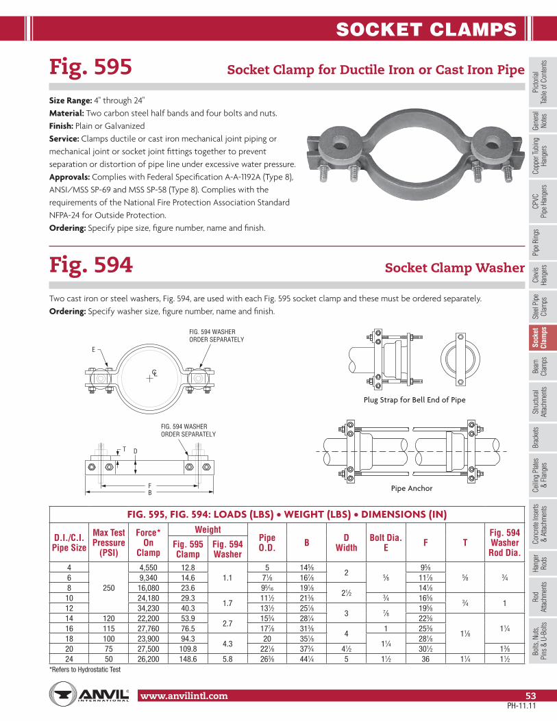
SOCKET CLAMPS
www.anvilintl.com 53
Copp
er Tu
bing
Ha
nger
sPi
pe R
ings
Clev
is Ha
nger
sSt
eel P
ipe
Clam
psSo
cket
Clam
psSt
ructu
ral
Attac
hmen
tsBr
acke
tsCe
iling
Plat
es&
Flan
ges
Conc
rete
Inse
rts&
Attac
hmen
tsHa
nger
Rods
Rod
Attac
hmen
tsBo
lts, N
uts,
Pins
& U
-Bol
tsBe
amCl
amps
Picto
rial
Tabl
e of C
onten
tsCP
VCPi
pe H
ange
rsGe
nera
lNo
tes
Fig. 595 Socket Clamp for Ductile Iron or Cast Iron Pipe
Size Range: 4" through 24"Material: Two carbon steel half bands and four bolts and nuts.Finish: Plain or GalvanizedService: Clamps ductile or cast iron mechanical joint piping or mechanical joint or socket joint fittings together to prevent separation or distortion of pipe line under excessive water pressure.Approvals: Complies with Federal Specification A-A-1192A (Type 8),ANSI/MSS SP-69 and MSS SP-58 (Type 8). Complies with therequirements of the National Fire Protection Association StandardNFPA-24 for Outside Protection.Ordering: Specify pipe size, figure number, name and finish.
FIG. 595, FIG. 594: LOADS (LBS) • WEIGHT (LBS) • DIMENSIONS (IN)
D.I./C.I. Pipe Size
Max Test Pressure
(PSI)
Force*On
Clamp
WeightPipe O.D. B D
WidthBolt Dia.
E F TFig. 594 Washer Rod Dia.
Fig. 595 Clamp
Fig. 594 Washer
4
250
4,550 12.81.1
5 145⁄82 5⁄8
95⁄85⁄8 3⁄46 9,340 14.6 71⁄8 167⁄8 117⁄8
8 16,080 23.6 95⁄16 191⁄821⁄2
141⁄810 24,180 29.3
1.7111⁄2 213⁄8 3⁄4 165⁄8 3⁄4 1
12 34,230 40.3 131⁄2 251⁄83 7⁄8
195⁄814 120 22,200 53.9
2.7153⁄4 281⁄4 223⁄8
11⁄811⁄416 115 27,760 76.5 177⁄8 313⁄8
41 253⁄8
18 100 23,900 94.34.3
20 351⁄811⁄4
281⁄820 75 27,500 109.8 221⁄8 373⁄4 41⁄2 301⁄2 13⁄824 50 26,200 148.6 5.8 263⁄8 441⁄4 5 11⁄2 36 11⁄4 11⁄2
*Refers to Hydrostatic Test
Fig. 594 Socket Clamp Washer
Two cast iron or steel washers, Fig. 594, are used with each Fig. 595 socket clamp and these must be ordered separately.Ordering: Specify washer size, figure number, name and finish.
F
FIG. 594 WASHERORDER SEPARATELY
D
E
T
B
FIG. 594 WASHERORDER SEPARATELY
CL
Plug Strap for Bell End of Pipe
Pipe Anchor
PH-11.11

SOCKET CLAMPS
www.anvilintl.com54
Fig. 600 Socket Clamp for Ductile Iron or Cast Iron Pipe
Size Range: 3" through 24" pipeMaterial: Two carbon steel halfbands and two bolts and nuts.Finish: Plain or GalvanizedService: Clamps joints of socket fittings together to preventdistortion of pipe line under excessive water pressure.Approvals: Complies with Federal Specification A-A-1192A (Type 8),ANSI/MSS SP-69 and MSS SP-58 (Type 8).Features: An economical method of anchoring joints of socketfittings when used on other than fire protection work.Ordering: Specify pipe size, figure number, name and finish.
FIG. 600, FIG. 599: WEIGHT (LBS) • DIMENSIONS (IN)
D.I./C.I. Pipe Size
WeightPipe O.D. B D
WidthBolt Dia.
E F TFig. 599: Washer Rod Dia.
Fig. 600: Clamp
Fig. 599: Washer
3 9.7
1.2
4 115⁄8
2 5⁄8
85⁄8
5⁄8 3⁄4
4 11.0 5 121⁄8 93⁄46 12.7 71⁄16 143⁄8 128 14.5 93⁄16 165⁄8 141⁄4
10 16.3 113⁄8 187⁄8 161⁄212 18.3 131⁄2 211⁄4 187⁄814 48.7
2.7153⁄4 251⁄2 3 7⁄8 23
11⁄811⁄416 69.2 177⁄8 28
41 251⁄2
18 82.04.5
20 311⁄211⁄4
275⁄820 97.5 221⁄8 333⁄4 41⁄2 293⁄4 13⁄824 132.0 6.8 263⁄8 393⁄4 5 11⁄2 351⁄4 11⁄4 11⁄2
Fig. 599 Socket Clamp Washer
Two cast iron or steel washers, Fig. 599, are used with each Fig. 600 socket clamp and these must be ordered separately.Ordering: Specify washer size, figure number, name and finish.
F
T
FIG. 599 WASHERORDER SEPARATELY
D
E
B
CL
PH-11.11

BEAM CLAMPS
www.anvilintl.com 55
Copp
er Tu
bing
Ha
nger
sPi
pe R
ings
Clev
is Ha
nger
sSt
eel P
ipe
Clam
psSo
cket
Clam
psSt
ructu
ral
Attac
hmen
tsBr
acke
tsCe
iling
Plat
es&
Flan
ges
Conc
rete
Inse
rts&
Attac
hmen
tsHa
nger
Rods
Rod
Attac
hmen
tsBo
lts, N
uts,
Pins
& U
-Bol
tsBe
amCl
amps
Picto
rial
Tabl
e of C
onten
tsCP
VCPi
pe H
ange
rsGe
nera
lNo
tes
Fig. 86: C-Clamp with Set Screw and Lock Nut C-Clamp
Fig. 88: C-Clamp with Set Screw Only
Size Range: 3⁄8" through 3⁄4"Material: Malleable iron clamp; hardened steel cup point set screw.Finish: Plain or GalvanizedService: Recommended for attachment to “W” and “M” beams where thickness of flange Z (see table page 234) does not exceed 0.75". When clamp is used with Fig. 89 retaining clip, flange thickness may not exceed 0.62".Approvals: Complies with Federal Specification A-A-1192A (Type 23), WW-H-171-E (Type 23), ANSI/MSS SP-69 and MSS SP-58 (Type 23). UL, ULC Listed (Sizes 3⁄8", 1⁄2" and 3⁄4") and FMApproved (Sizes 3⁄8").Installation: Follow recommended set screw torque values per MSS-SP-69 (See table on page 233).The Fig. 88 is only to be used on installations where the clamp cannot become dislodgedfrom the beam.Features:
• Malleable body assures: 1) Uniform quality and strength. 2) Full thread engagement.• Hardened steel cup point set screw for securing to beam flange.• Ribbed design of clamp provides added strength.
Ordering: Specify rod size, figure number, name, length of retaining clip, if desired. (Add 2" to flange width of beam to arrive at proper length of retaining clip.) If required length is not standard, order next longer standard.
FIG. 86 AND FIG. 88: LOADS (LBS) • WEIGHT (LBS) • DIMENSIONS (IN) • TORQUE (IN-LBS)
Rod Size A Torque Value Max Load ■ C E HWeight
Fig. 86 Fig. 883⁄8 60
400 13⁄4 5⁄8 13⁄80.28 0.26
1⁄2 60 0.31 0.295⁄8 60 440
2 3⁄4 11⁄20.42 0.40
3⁄4 60 500 0.55 0.53
■ Maximum temperature of 450° F.
3⁄4"
3⁄8"3⁄8"
H
Z
E
C
A
Fig. 89X
3⁄4"
3⁄8"
HE
CZ
Fig. 89
A
Fig. 86
Fig. 88Fig. 86
PH-11.11

BEAM CLAMPS
www.anvilintl.com56
Fig. 95 C-Clamp with Locknut
Size Range: 3⁄8" and 1⁄2"Material: Carbon SteelFinish: Plain or GalvanizedService: Designed for fastening flange of “W” and “M” beam. Bottom hole tapped to accommodate hanger rod.Approvals: Complies with Federal Specification A-A-1192A (Type 23) WW-H-171-E (Type 23), ANSI/MSS SP-69 and MSS SP-58 (Type 23). UL Listed (Sizes 3⁄8"). FM Approved (Sizes 3⁄8" - 1⁄2").Installation: Follow recommended set screw torque values per MSS-SP-69 (See table on page 233).Ordering: Specify rod size, figure number, name and finish.Note: If a retaining clip is desired, you may specify either Fig. 89X or Fig. 89. For length and other ordering information, refer to Fig. 89X and Fig. 89.
FIG. 95: LOAD (LBS) • WEIGHT (LBS) • DIMENSIONS (IN) • TORQUE (IN-LBS) Rod Sized Retaining Clips
Rod Size A
Set Screw Size
TorqueValue
Max Load B C D Weight Fig. 89 Fig. 89X
3⁄8 3⁄8 60 2303⁄4 21⁄4 23⁄8
0.343⁄8
3⁄8
1⁄2 1⁄2 125 380 0.40 1⁄2
SetScrew
BD
C
A
PH-11.11
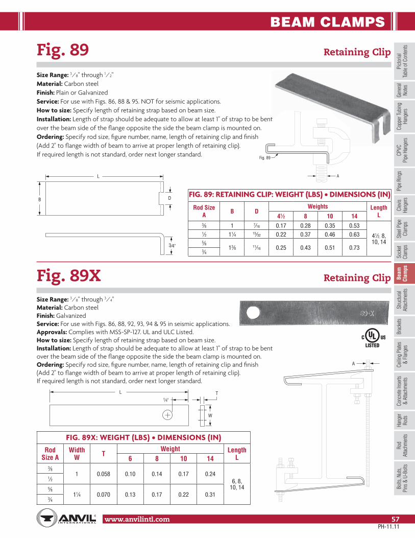
BEAM CLAMPS
www.anvilintl.com 57
Copp
er Tu
bing
Ha
nger
sPi
pe R
ings
Clev
is Ha
nger
sSt
eel P
ipe
Clam
psSo
cket
Clam
psSt
ructu
ral
Attac
hmen
tsBr
acke
tsCe
iling
Plat
es&
Flan
ges
Conc
rete
Inse
rts&
Attac
hmen
tsHa
nger
Rods
Rod
Attac
hmen
tsBo
lts, N
uts,
Pins
& U
-Bol
tsBe
amCl
amps
Picto
rial
Tabl
e of C
onten
tsCP
VCPi
pe H
ange
rsGe
nera
lNo
tes
Fig. 89 Retaining Clip
Size Range: 3⁄8" through 1⁄2"Material: Carbon steelFinish: Plain or GalvanizedService: For use with Figs. 86, 88 & 95. NOT for seismic applications.How to size: Specify length of retaining strap based on beam size.Installation: Length of strap should be adequate to allow at least 1" of strap to be bent over the beam side of the flange opposite the side the beam clamp is mounted on.Ordering: Specify rod size, figure number, name, length of retaining clip and finish(Add 2" to flange width of beam to arrive at proper length of retaining clip). If required length is not standard, order next longer standard.
Fig. 89X Retaining Clip
Size Range: 3⁄8" through 3⁄4"Material: Carbon steelFinish: GalvanizedService: For use with Figs. 86, 88, 92, 93, 94 & 95 in seismic applications.Approvals: Complies with MSS-SP-127. UL and ULC Listed.How to size: Specify length of retaining strap based on beam size.Installation: Length of strap should be adequate to allow at least 1" of strap to be bent over the beam side of the flange opposite the side the beam clamp is mounted on.Ordering: Specify rod size, figure number, name, length of retaining clip and finish (Add 2" to flange width of beam to arrive at proper length of retaining clip). If required length is not standard, order next longer standard.
FIG. 89X: WEIGHT (LBS) • DIMENSIONS (IN)
Rod Size A
Width W T
Weight Length L6 8 10 14
3⁄81 0.058 0.10 0.14 0.17 0.24
6, 8, 10, 14
1⁄25⁄8
11⁄4 0.070 0.13 0.17 0.22 0.313⁄4
FIG. 89: RETAINING CLIP: WEIGHT (LBS) • DIMENSIONS (IN)
Rod SizeA B D
Weights Length L41⁄2 8 10 14
3⁄8 1 7⁄16 0.17 0.28 0.35 0.53
41⁄2, 8,10, 14
1⁄2 11⁄4 15⁄32 0.22 0.37 0.46 0.635⁄8
13⁄8 11⁄16 0.25 0.43 0.51 0.733⁄4
A
Fig. 89
3⁄4"
DB
L
A
L
W
T1⁄4"
PH-11.11

BEAM CLAMPS
www.anvilintl.com58
Fig. 92 Universal C-type Clamp (Standard Throat)
Size Range: 3⁄8" and 1⁄2"Material: Ductile iron, hardened steel cup point set screw and locknut.Finish: Plain or GalvanizedService: Recommended for use under roof installations with bar joist type construction, or for attachment to the top or bottom flange of structural shapes where the vertical hanger rod is required to be offset from the edge of the flange and where the thickness of joist or flange does not exceed 3⁄4".Approvals: Complies with Federal Specification A-A-1192A (Type 19 & 23) WW-H-171-E (Type 23), ANSI/MSS SP-69 and MSS SP-58 (Type 19 & 23). UL, ULC Listed and FM Approved.How to size: Size of clamp is determined by size of rod to be used.Installation: Follow recommended set screw torque values per MSS-SP-69 (See table on page 233)Features:
• They may be attached to horizontal flanges of structural members in either the top beam or bottom beam positions.• Secured in place by a cup-pointed Set Screw tightened against the flange. A Jam Nut is provided for tightening the Set Screw against the Body Casting.• Thru tapping of the body casting permits extended adjustment of the threaded rod.• Can be used with Fig 89X retaining clip for seismic applications.
Ordering: Specify rod size, figure number, name of clamp and finish.
FIG. 92: LOAD (LBS) • WEIGHT (LBS) • DIMENSIONS (IN) • TORQUE (IN-LBS)
Rod Size A
Set Screw Size
TorqueValue
Max Loads ■Weight C D E F G H
Top Bottom3⁄8 3⁄8 60 500 250 0.34 15⁄16 19⁄16 9⁄16 13⁄16 3⁄8 1⁄2
1⁄2 1⁄2 125 950 760 0.63 13⁄8 113⁄16 1⁄2 11⁄16 7⁄16 23⁄32
■ Maximum temperature of 450° F
F
D
AT LEAST ONEFULL THREADOF ROD MUSTBE EXPOSED
H CE
G
3⁄4"
JAM - NUT
SET SCREW
1"
BODYCASTING
A
PH-11.11
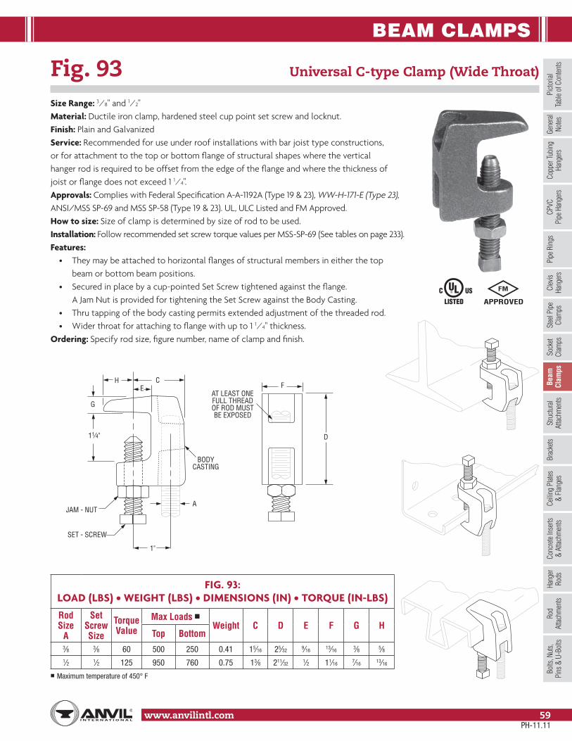
BEAM CLAMPS
www.anvilintl.com 59
Copp
er Tu
bing
Ha
nger
sPi
pe R
ings
Clev
is Ha
nger
sSt
eel P
ipe
Clam
psSo
cket
Clam
psSt
ructu
ral
Attac
hmen
tsBr
acke
tsCe
iling
Plat
es&
Flan
ges
Conc
rete
Inse
rts&
Attac
hmen
tsHa
nger
Rods
Rod
Attac
hmen
tsBo
lts, N
uts,
Pins
& U
-Bol
tsBe
amCl
amps
Picto
rial
Tabl
e of C
onten
tsCP
VCPi
pe H
ange
rsGe
nera
lNo
tes
Fig. 93 Universal C-type Clamp (Wide Throat)
Size Range: 3⁄8" and 1⁄2"Material: Ductile iron clamp, hardened steel cup point set screw and locknut.Finish: Plain and GalvanizedService: Recommended for use under roof installations with bar joist type constructions,or for attachment to the top or bottom flange of structural shapes where the verticalhanger rod is required to be offset from the edge of the flange and where the thickness ofjoist or flange does not exceed 1 1⁄4".Approvals: Complies with Federal Specification A-A-1192A (Type 19 & 23), WW-H-171-E (Type 23),ANSI/MSS SP-69 and MSS SP-58 (Type 19 & 23). UL, ULC Listed and FM Approved.How to size: Size of clamp is determined by size of rod to be used.Installation: Follow recommended set screw torque values per MSS-SP-69 (See tables on page 233).Features:
• They may be attached to horizontal flanges of structural members in either the top beam or bottom beam positions.• Secured in place by a cup-pointed Set Screw tightened against the flange. A Jam Nut is provided for tightening the Set Screw against the Body Casting.• Thru tapping of the body casting permits extended adjustment of the threaded rod.• Wider throat for attaching to flange with up to 1 1⁄4" thickness.
Ordering: Specify rod size, figure number, name of clamp and finish.
FIG. 93:LOAD (LBS) • WEIGHT (LBS) • DIMENSIONS (IN) • TORQUE (IN-LBS)
Rod Size
A
Set Screw Size
TorqueValue
Max Loads ■Weight C D E F G H
Top Bottom3⁄8 3⁄8 60 500 250 0.41 15⁄16 25⁄32 9⁄16 13⁄16 3⁄8 5⁄81⁄2 1⁄2 125 950 760 0.75 13⁄8 211⁄32 1⁄2 11⁄16 7⁄16 13⁄16
■ Maximum temperature of 450° F
F
D
AT LEAST ONEFULL THREADOF ROD MUSTBE EXPOSED
H CE
G
11⁄4"
JAM - NUT
1"
SET - SCREW
BODYCASTING
A
PH-11.11

BEAM CLAMPS
www.anvilintl.com60
Fig. 94 Wide Throat Top Beam C-Clamp
Size Range: 5⁄8" and 3⁄4"Material: Ductile iron body, hardened steel cup point set screw and locknut.Finish: Plain or GalvanizedService: Recommended for use under roof installations with bar joist type construction, or for attachment to the top flange of structural shapes where the vertical hanger rod is required to be offset from the edge of the flange and where the thickness of joists or flange does not exceed 1 5⁄16".Approvals: Complies with Federal Specification A-A-1192A (Type 19) WW-H-171-E (Type 19), ANSI/MSS SP-69 and MSS SP-58 (Type 19), UL Listed.How to size: Size of clamp is determined by size of rod to be used.Installation: Follow maximum recommended set screw torque values per MSS-SP-69. (See tables on page 233)Features:
• Provides clamping to bar joists which are directly under roof installations.• Provides for vertical hanger rod installed offset from the edge of the beam flange.• Malleable iron body assures full thread engagement of rod.
Ordering: Specify rod size, figure number, name of clamp and finish.
FIG. 94: LOAD (LBS) • WEIGHT (LBS) • DIMENSIONS (IN) • TORQUE (IN-LBS)Rod Size A Set Screw Size Torque Value Max Loads ■ Weight B C D E F
5⁄8 3/8 60 1,200 0.66 13⁄4 21⁄43⁄4
11⁄4 13⁄4 3/8 60 1,600 0.83 17⁄8 23⁄8 13⁄8 13⁄16
■ Maximum temperature of 450° F
15/16
3/8
DB
C
A
E
F
PH-11.11

BEAM CLAMPS
www.anvilintl.com 61
Copp
er Tu
bing
Ha
nger
sPi
pe R
ings
Clev
is Ha
nger
sSt
eel P
ipe
Clam
psSo
cket
Clam
psSt
ructu
ral
Attac
hmen
tsBr
acke
tsCe
iling
Plat
es&
Flan
ges
Conc
rete
Inse
rts&
Attac
hmen
tsHa
nger
Rods
Rod
Attac
hmen
tsBo
lts, N
uts,
Pins
& U
-Bol
tsBe
amCl
amps
Picto
rial
Tabl
e of C
onten
tsCP
VCPi
pe H
ange
rsGe
nera
lNo
tes
Fig. 227 Top Beam Clamp
Material: Carbon steel jaw, hook rod with nut, lock washer and plain washer.Finish: PlainService: Recommended for use on top flange of beam and roof trusses where the flange thickness does not exceed 0.81".Approvals: Complies with Federal Specification A-A-1192A (Type 25),ANSI/MSS SP-69 and MSS SP-58 (Type 25). UL Listed (rod sizes 3⁄8" & 1⁄2")and FM Approved when used with 3⁄8" rod size.How to size: Determine hook rod length by adding figure in column headed “x” to flange width (see table on page 234 for flange width). “x” is not indicated as a dimension on drawing.Installation: Slide stamped steel jaw over beam flange and attach hook rod and eye rod, finally tightening hook rod. Hammer jaw firmly against the underside of the beam to complete installation.Features:
• Two jaw sizes fit beam flanges thickness from 0.25" to 0.81".• Clamp firmly holds to beam providing safe and extremely economical means of supporting small piping from the top flange of steel beams and roof trusses.
Ordering: Specify jaw size, figure number, name, hook rod length. Standard hook rods are furnished in even inch lengths, either length ordered or next longer length.
FIG. 227: LOADS (LBS) • WEIGHT (LBS) • DIMENSIONS (IN)
Jaw Size Max Load Weight ▲ Hook Rod Diam Rod Size A B C X
1 730 0.38 3⁄8 3⁄8 3⁄4 5⁄16 21⁄8
2 940 0.67 1⁄2
1⁄2 1 3⁄8 21⁄45⁄8 11⁄8 7⁄16 21⁄23⁄4 11⁄4 1⁄2 25⁄8
▲ Based on 8" hook rod length. Will vary for other hook rod lengths.
C
A
B
PH-11.11

BEAM CLAMPS
www.anvilintl.com62
Fig. 217 Adjustable Side Beam Clamp
Size Range: 3" through 7 5⁄8"Material: Carbon steelFinish: PlainService: To be used where it is necessary for the hanger rodto run vertically close to the beams edge, eliminating drillingof holes in structural members.Components: Top slide, bottom hook, nut and bolt – assembled.Design: Can be adjusted to fit various beam flange widths and thicknesses.Approvals: Complies with Federal Specification A-A-1192A(Type 25), ANSI/MSS SP-69 and MSS SP-58 (Type 25).Ordering: Specify size, figure number, type, name.
Fig. 14 Adjustable Side Beam Clamp
Size Range: 3⁄8" through 5⁄8"Material: Carbon steelFinish: Plain or GalvanizedService: Recommended for supporting pipe from the bottom flange of beams.Approvals: Complies with Federal Specification A-A-1192A (Type 27) WW-H-171-E (Type 54), ANSI/MSS SP-69 and MSS SP-58 (Type 27).Ordering: Specify rod size, figure number, name and finish.
FIG. 14: LOAD (LBS) • WEIGHT (LBS) • DIMENSIONS (IN)
Rod Size A
Max Load
Hole Size A
Adjustment Beam Width Weight
Min. Max.3⁄8 300 7⁄16
31⁄2 8
1.19
1⁄2 700 9⁄16 1.67
5⁄8 1,000 11⁄16 2.23
FIG. 217: LOAD (LBS) • WEIGHT (LBS) • DIMENSIONS (IN)
Size Max Flange Width
Max Flange Thickness
Rod Size A
Max Load Weight
Fig. 217 - Type 13 3 - 41⁄2 1⁄2
3⁄8 300
0.8045⁄8 45⁄8 - 6 11⁄16 1.0661⁄8 61⁄8 - 71⁄2 3⁄4 1.1775⁄8 75⁄8 - 9 15⁄16 1.28
Fig. 217 - Type 23 3 - 41⁄2 1⁄2
1⁄2 500
1.5745⁄8 45⁄8 - 6 11⁄16 1.8461⁄8 61⁄8 - 71⁄2 3⁄4 2.0575⁄8 75⁄8 - 9 15⁄16 2.23
Fig. 217 - Type 33 3 - 41⁄2 1⁄2
5⁄8 700
3.7545⁄8 45⁄8 - 6 11⁄16 4.1961⁄8 61⁄8 - 71⁄2 3⁄4 4.5375⁄8 75⁄8 - 9 15⁄16 5.11
21⁄2"
2
A
A
PH-11.11

BEAM CLAMPS
www.anvilintl.com 63
Copp
er Tu
bing
Ha
nger
sPi
pe R
ings
Clev
is Ha
nger
sSt
eel P
ipe
Clam
psSo
cket
Clam
psSt
ructu
ral
Attac
hmen
tsBr
acke
tsCe
iling
Plat
es&
Flan
ges
Conc
rete
Inse
rts&
Attac
hmen
tsHa
nger
Rods
Rod
Attac
hmen
tsBo
lts, N
uts,
Pins
& U
-Bol
tsBe
amCl
amps
Picto
rial
Tabl
e of C
onten
tsCP
VCPi
pe H
ange
rsGe
nera
lNo
tes
Fig. 133 Standard Duty Beam Clamp
Fig. 134 Heavy Duty Beam Clamp
Size Range: 4" through 12"Material: Carbon steelFinish: Plain or GalvanizedService: Clamp centers the load on beam to prevent distortionApprovals: Complies with Federal Specification A-A-1192A (Type 21) WW-H-171-E (Type 21), ANSI/MSS SP-69 and MSS SP-58 (Type 21). Fig. 133 UL Listed when used with 3⁄8" and 1⁄2" rod. Fig. 134 UL Listed and FM Approved when used with 1⁄2" and 5⁄8" rod.Components: Two half-clamps, pipe spacer and bolt with nut assembled.Ordering: Figure number, width of flange, name and finish.Note: Spacer is furnished for use with Fig. 290 weldless eye nuts. Spacer may be removed for use with Fig 278 eye rods.
Flange Size
Flange Width
Max Flange Thickness
Weight (lbs)
Fig. 133 Std. Duty
Fig. 134 Heavy Duty
4 1⁄2 0.91 3.82
5 5⁄8 1.00 4.35
6 3⁄4 1.15 4.52
77⁄8
1.29 4.84
8 1.44 5.10
9
1
– 5.83
10 – 6.25
11 – 6.67
12 – 7.09
FIG. 133, 134: LOADS (LBS) • DIMENSIONS (IN)
C B Bolt Size
Spacer O.D.
Max Load
Fig. 133 1⁄2 13⁄8 3⁄8 11⁄16 1,000
Fig. 134 3⁄4 21⁄4 5⁄8 11⁄16 3,000
Fig. 133Standard Duty
Fig. 134Heavy Duty
Spacer
Bolt C
B
PH-11.11
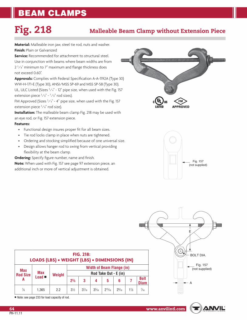
BEAM CLAMPS
www.anvilintl.com64
E
A
BOLT DIA.
Fig. 157(not supplied)
Fig. 218 Malleable Beam Clamp without Extension Piece
Material: Malleable iron jaw, steel tie rod, nuts and washer.Finish: Plain or GalvanizedService: Recommended for attachment to structural steel. Use in conjunction with beams where beam widths are from 2 3⁄8" minimum to 7" maximum and flange thickness does not exceed 0.60".Approvals: Complies with Federal Specification A-A-1192A (Type 30) WW-H-171-E (Type 30), ANSI/MSS SP-69 and MSS SP-58 (Type 30). UL, ULC Listed (Sizes 3⁄4" - 12" pipe size, when used with the Fig. 157 extension piece 3⁄8" - 7⁄8" rod sizes). FM Approved (Sizes 3⁄4" - 4” pipe size, when used with the Fig. 157 extension piece 3⁄8" rod size).Installation: The malleable beam clamp Fig. 218 may be used with an eye rod, or Fig. 157 extension piece.Features:
• Functional design insures proper fit for all beam sizes.• Tie rod locks clamp in place when nuts are tightened.• Ordering and stocking simplified because of one universal size.• Design allows hanger rod to swing from vertical providing flexibility at the beam clamp.
Ordering: Specify figure number, name and finish.Note: When used with Fig. 157 see page 97 extension piece, an additional inch or more of vertical adjustment is obtained.
FIG. 218:LOADS (LBS) • WEIGHT (LBS) • DIMENSIONS (IN)
Max Rod Size
A
Max Load ■ Weight
Width of Beam Flange (in)Rod Take Out - E (in)
23⁄8 3 4 5 6 7 Bolt Diam
7⁄8 1,365 2.2 31⁄2 37⁄16 35⁄16 215⁄16 29⁄16 17⁄8 7⁄16
■ Note: see page 233 for load capacity of rod.
Fig. 157(not supplied)
PH-11.11

BEAM CLAMPS
www.anvilintl.com 65
Copp
er Tu
bing
Ha
nger
sPi
pe R
ings
Clev
is Ha
nger
sSt
eel P
ipe
Clam
psSo
cket
Clam
psSt
ructu
ral
Attac
hmen
tsBr
acke
tsCe
iling
Plat
es&
Flan
ges
Conc
rete
Inse
rts&
Attac
hmen
tsHa
nger
Rods
Rod
Attac
hmen
tsBo
lts, N
uts,
Pins
& U
-Bol
tsBe
amCl
amps
Picto
rial
Tabl
e of C
onten
tsCP
VCPi
pe H
ange
rsGe
nera
lNo
tes
Fig. 228 Universal Forged Steel (UFS) Beam Clamp with UFS (Upper) Nut Right-Hand Thread
Material: Forged steelFinish: Plain or GalvanizedService: For suspension of heavy loads from beams with flange widths to 15" and flange thickness to 1.031.Approvals: Complies with Federal Specification A-A-1192A(Type 28 without links; Type 29 with links), WW-H-171-E (Type 30 & 31),ANSI/MSS SP-69 and MSS SP-58 (Type 28 without links; Type 29 with links).Installation: Fit jaws over edges of lower beam flange and tighten nuts on tie rod to lock clamp in place.Features:
• Upper nut is tapped to any specified size up to the maximum rod size.• Quickly, easily, economically installed.• Tie rod insures a tight non-slip fit to the beam.• Clamps are available, tapped to any specified rod size up to the maximum rod size.
Ordering: Specify clamp size, figure number, name, rod size and finish.Note: The application of a load to a structural beam by means of a beam clamp produces a transverse stress, perpendicular to the axis of the beam, in the flange to which the load is applied. Size per load, beam flange width and rod size
FIG. 228: LOADS (LBS) • WEIGHT (LBS) • DIMENSIONS (IN)
Clamp Size No.
Max Rod Size A
Max Load ■ Weight Z Max ✥ B
Jaw and Nut Size
▲
1 5⁄8 2,160 3.30.60
11⁄16 228 - 12 7⁄8 4,480
7.013⁄8 228 - 2
10.64
11⁄2 11,50019.3
1.031 23⁄8 228 - 331.0
▲ For reference only, order by clamp size.
■ Note: Load capacity based on rod sizes shown. For load capacity of other rod sizes see page 233.✥ For actual “Z” dimensions see table on page 234.
Clamp Size No.
Width of Beam Flange (in)Rod Take Out - E (in)
3 4 5 6 7 8 9 10 11 12 13 14 151 19⁄16 11⁄2
15⁄16 11⁄83⁄4 – – – – – – – –
2 – 17⁄16 11⁄16 – – – – – – – –– – – – 115⁄16 113⁄16 11⁄2
15⁄16– – – – –
4 – 25⁄16 23⁄16 21⁄16 113⁄16 17⁄8 19⁄16 – – – – –– – – – – – – 3 211⁄16 29⁄16 21⁄4 115⁄16 15⁄8
A
B
Z
11⁄8"
E
A
B
E
11⁄8"
Z
Fig. 228(without Links)
Fig. 228(with Links)
PH-11.11

BEAM CLAMPS
www.anvilintl.com66
Fig. 292: Right-Hand Thread Universal Forged Steel (UFS) Beam Clamp
Fig. 292L: Left-Hand Thread with Weldless Eye Nut
Material: Forged steelFinish: Plain or GalvanizedService: For suspension of heavy loads from beams withflange widths to 15" and flange thickness to 1.031.Approvals: Complies with Federal Specification A-A-1192A(Type 28 without links; Type 29 with links), WW-H-171-E(Type 28 without links; Type 29 with links), ANSI/MSS SP-69 andMSS SP-58 (Type 28 without links; Type 29 with links).Installation: Fit jaws over edges of lower beam flange and tightennuts on tie rod to lock clamp in place.Features:
• Weldless eye nut provides for horizontal pipe movement without binding.• Weldless eye nut is furnished tapped to any specified rod size up to the maximum rod size.• Tie rod assures a tight non-slip fit to the beam.• Self locking nut with a nylon insert prevents the nut from working loose.
Ordering: Specify clamp size, figure number, name, rod size and finish.Note: The application of a load to a structural beam by means of a beam clamp produces a transverse stress, perpendicular to the axis of the beam, in the flange to which the load is applied.
FIG. 292, FIG. 292L: LOADS (LBS) • WEIGHT (LBS) • DIMENSIONS (IN)
Clamp Size No.
Max Rod Size A
Max Load ■ Weight Z Max ✥ B
Jaw and Eye Nut Size ▲
1 3⁄4 3,230 3.90.60
11⁄4 292 - 1 / 12
1 5,900
9.2111⁄16 292 - 2 / 2
13.04 21.7
1.031
11⁄2 292 - 3 / 233.9
611⁄2
11,50023.9
21⁄8 292 - 3 / 335.8
8 2 36.8 49⁄16 292 - 3 / 4▲ For reference only, order by clamp size.
■ Note: Load capacity based on rod sizes shown. For load capacity of other rod sizes see page 233.✥ For actual “Z” dimensions see table on page 234.
Clamp Size No.
Width of Beam Flange (in)Rod Take Out - E (in)
3 4 5 6 7 8 9 10 11 12 13 14 151 41⁄2 45⁄16 41⁄16 35⁄8 27⁄8 – – – – – – – –2 – 43⁄4 47⁄16 41⁄16 33⁄8 – – – – – – – –
– – – – 515⁄16 6 55⁄16 5 – – – – –4 – 613⁄16 65⁄8 63⁄8 57⁄8 57⁄8 53⁄8 413⁄16 – – – – –
– – – – – – – – 81⁄8 73⁄4 71⁄8 65⁄8 61⁄16
6 – 73⁄16 7 63⁄4 61⁄4 65⁄16 513⁄16 53⁄16 – – – – –– – – – – – – – 81⁄2 81⁄8 71⁄2 7 67⁄16
8 – 85⁄8 87⁄16 83⁄16 73⁄4 73⁄4 71⁄4 65⁄8 – – – – – A
B
Z
E
11/8
SELF LOCKINGNUTS (3X)
A
11/8
B
E
Z
SELF LOCKING NUT
Fig. 292(with Links)
Fig. 292(without Links)
PH-11.11

STRUCTURAL ATTACHMENTS
www.anvilintl.com 67
Copp
er Tu
bing
Ha
nger
sPi
pe R
ings
Clev
is Ha
nger
sSt
eel P
ipe
Clam
psSo
cket
Clam
psSt
ruct
ural
Atta
chm
ents
Brac
kets
Ceili
ng P
lates
& Fl
ange
sCo
ncre
te In
serts
& At
tachm
ents
Hang
erRo
dsRo
d At
tachm
ents
Bolts
, Nut
s,Pi
ns &
U-B
olts
Beam
Clam
psPi
ctoria
lTa
ble o
f Con
tents
CPVC
Pipe
Han
gers
Gene
ral
Notes
Fig. 55 (Short) Structural Welding Lug
Fig. 55L (Long) Size Range: Fig. 55: 1⁄2" through 3 3⁄4"
Fig. 55L 1⁄2" through 2"Material: Carbon steelFinish: Plain or GalvanizedService: For attachment to structural steel in conjunction with the Fig. 299 clevis and with type C variable spring hanger or Type C Constant Support.Maximum Temperature: Plain 750° F, Galvanized 450° FApprovals: Complies with Federal Specification A-A-1192A (Type 57), WW-H-171-E (Type 57),ANSI/MSS SP-69 and MSS SP-58 (Type 57).Ordering: Specify rod size, figure number, name, finish and whether short or long lug is required.Order Separately: Fig. 291 pin with cotters or bolt and nut
FIG. 55, FIG. 55L: LOAD (LBS) • WEIGHT (LBS) • DIMENSIONS (IN)Fig. 55, Fig. 55L Fig. 55 (Short) Fig. 55L (Long)
Rod Size A*
Pin or Bolt Dia. F R T W
Max Load Rod Take Out - H Weight Rod Take
Out - H Weight650˚ F 750˚ F
1⁄2 5⁄8 11⁄16
11⁄4
1⁄4
21⁄2
1,350 1,057
11⁄2
0.48
3
0.755⁄8 3⁄4 13⁄16 2,160 1,692 0.41 0.683⁄4 7⁄8 15⁄16
3⁄83,230 2,530 0.60 1.0
7⁄8 1 11⁄8 4,480 3,5082
0.71 0.98
1 11⁄8 11⁄4 11⁄2 1⁄2 3 5,900 4,620 1.2 1.6
11⁄4 13⁄8 11⁄2 2 5⁄8 4 9,500 7,440
3
3.0 4 3.7
11⁄2 15⁄8 13⁄421⁄2
3⁄4
513,800 10,807 4.8
41⁄2
6.4
13⁄4 17⁄8 2 18,600 14,566 4.7 6.3
2 21⁄4 23⁄83 6
24,600 19,265 4 7.2 8.8
21⁄4 21⁄2 25⁄8 32,300 25,295
41⁄2
7.6 – –
21⁄2 23⁄4 27⁄8
41
8
39,800 31,169 15.5 – –
23⁄4 3 31⁄8 49,400 38,687 15.1 – –
3 31⁄4 33⁄8 60,100 47,0665
16.0 – –
31⁄4 31⁄2 35⁄8
41⁄2 9
71,900 56,307 18.9 – –
31⁄2 33⁄4 37⁄8 11⁄2 84,700 66,3316
31.3 – –
33⁄4 4 41⁄8 13⁄4 98,500 77,139 35.9 – –
* Note: Rod size “A” is the assembly rod diameter. Dimension not shown on drawing
T
F
W
H
R
FIELDWELD
FIELDWELD
PH-11.11
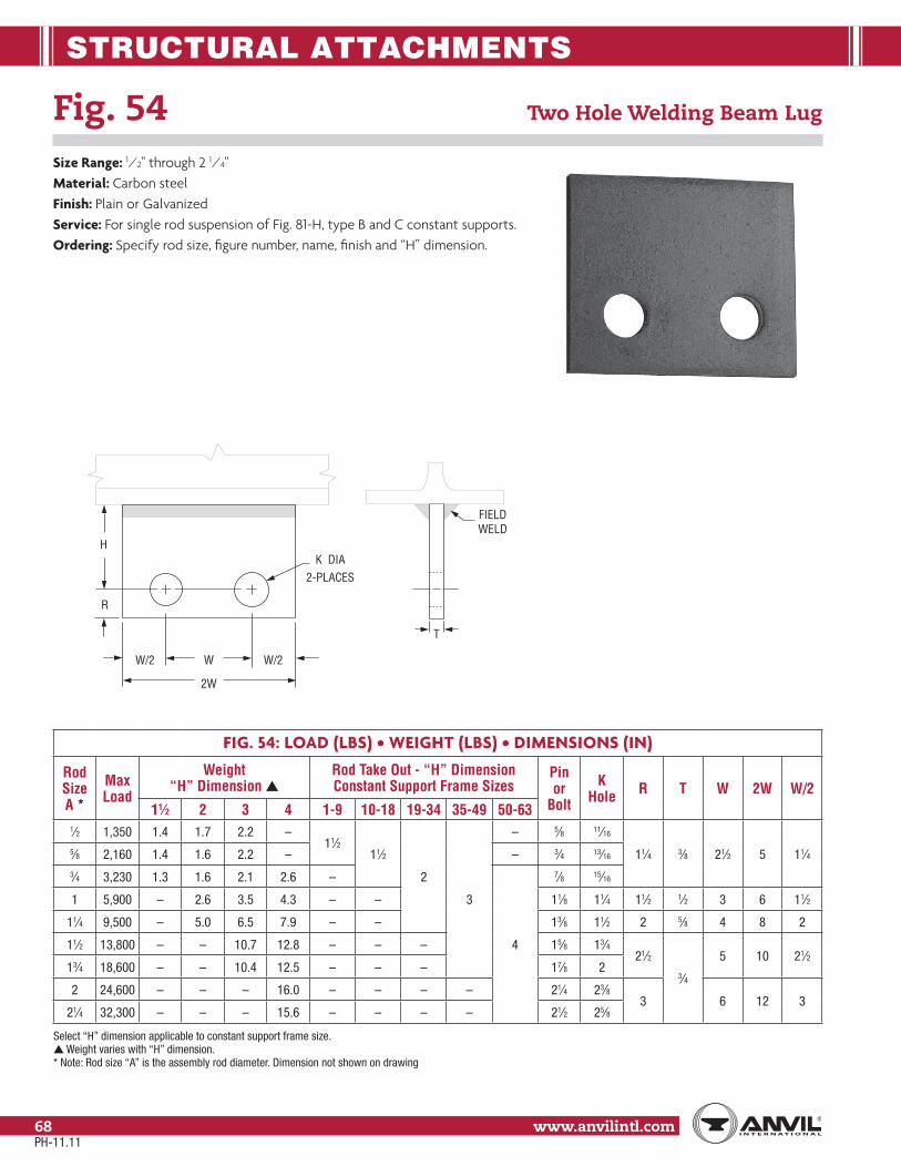
STRUCTURAL ATTACHMENTS
www.anvilintl.com68
Fig. 54 Two Hole Welding Beam Lug
Size Range: 1⁄2" through 2 1⁄4"Material: Carbon steelFinish: Plain or GalvanizedService: For single rod suspension of Fig. 81-H, type B and C constant supports.Ordering: Specify rod size, figure number, name, finish and “H” dimension.
FIG. 54: LOAD (LBS) • WEIGHT (LBS) • DIMENSIONS (IN)
Rod Size A *
Max Load
Weight “H” Dimension ▲
Rod Take Out - “H” Dimension Constant Support Frame Sizes
Pin or
Bolt
K Hole R T W 2W W/2
11⁄2 2 3 4 1-9 10-18 19-34 35-49 50-631⁄2 1,350 1.4 1.7 2.2 –
11⁄211⁄2
2
3
– 5⁄8 11⁄16
11⁄4 3⁄8 21⁄2 5 11⁄45⁄8 2,160 1.4 1.6 2.2 – – 3⁄4 13⁄16
3⁄4 3,230 1.3 1.6 2.1 2.6 –
4
7⁄8 15⁄16
1 5,900 – 2.6 3.5 4.3 – – 11⁄8 11⁄4 11⁄2 1⁄2 3 6 11⁄2
11⁄4 9,500 – 5.0 6.5 7.9 – – 13⁄8 11⁄2 2 5⁄8 4 8 2
11⁄2 13,800 – – 10.7 12.8 – – – 15⁄8 13⁄421⁄2
3⁄4
5 10 21⁄213⁄4 18,600 – – 10.4 12.5 – – – 17⁄8 2
2 24,600 – – – 16.0 – – – – 21⁄4 23⁄83 6 12 3
21⁄4 32,300 – – – 15.6 – – – – 21⁄2 25⁄8
Select “H” dimension applicable to constant support frame size.▲ Weight varies with “H” dimension.* Note: Rod size “A” is the assembly rod diameter. Dimension not shown on drawing
2W
WW/2 W/2
R
HK DIA
2-PLACES
T
FIELDWELD
PH-11.11

STRUCTURAL ATTACHMENTS
www.anvilintl.com 69
Copp
er Tu
bing
Ha
nger
sPi
pe R
ings
Clev
is Ha
nger
sSt
eel P
ipe
Clam
psSo
cket
Clam
psSt
ruct
ural
Atta
chm
ents
Brac
kets
Ceili
ng P
lates
& Fl
ange
sCo
ncre
te In
serts
& At
tachm
ents
Hang
erRo
dsRo
d At
tachm
ents
Bolts
, Nut
s,Pi
ns &
U-B
olts
Beam
Clam
psPi
ctoria
lTa
ble o
f Con
tents
CPVC
Pipe
Han
gers
Gene
ral
Notes
Fig: 66 Welded Beam Attachment
Size Range: 3⁄8" through 3 1⁄2"Material: Carbon steelFinish: Plain or GalvanizedService: Recommended for attachment to bottom of beams, especially where loads are considerable and rod sizes are large.Maximum Temperature: Plain 750° F, Galvanized 450° FApprovals: Complies with Federal Specification A-A-1192A (Type 22), WW-H-171-E (Type 22),ANSI/MSS SP-69 and MSS SP-58 (Type 22).Installation: If flexibility at the beam is desired, use with bolt and eye rod Fig. 278, page 93, or with weldless eye nut Fig. 290, page 97. If vertical adjustment is desired, use with threaded rod and nut and weld the attachment in an inverted position to the beam.Features:
• Will accommodate very heavy loads and rod sizes through 3 1⁄2".• Can be installed so as to provide for either flexibility or for vertical adjustment.• Versatility affords economical stocking and erection.• Beam size need not be considered.
Ordering: Specify rod size, figure number, name and finish. Sizes 1" and smaller are typicallysupplied with a bolt and nut. Sizes 11/4" and larger are typically supplied with a pin and cotters.
FIG: 66: LOAD (LBS) • WEIGHT (LBS) • DIMENSIONS (IN)
Rod Size
A
Pin or Bolt Size
Max Load Weight Rod Take OutB H R S T
650° F 750° F Without Bolt and Nut
With Bolt and Nut E E’
3⁄8 1⁄2 x 21⁄2 730 5720.96
1.2 17⁄8
22
9⁄16
7⁄8 11⁄4 1⁄41⁄2 5⁄8 x 21⁄2 1,350 1,057 1.313⁄4
11⁄16
5⁄8 3⁄4 x 23⁄4 2,160 1,692 1.6 13⁄16
3⁄4 7⁄8 x 4 3,230 2,530 1.9 2.821⁄2
15⁄16 11⁄8 17⁄8 3⁄87⁄8 1 x 4 4,480 3,508 2.5 3.9 25⁄83
11⁄8 11⁄4 21 11⁄8 x 5 5,900 4,620 4.3 6.3 23⁄4 3 11⁄4 11⁄2
21⁄21⁄2
11⁄4 13⁄8 x 53⁄8 9,500 7,440 8.1 10.2 27⁄8 4 11⁄2 2 5⁄811⁄2 15⁄8 x 6 13,800 10,807 – 19.0 – 4
513⁄4 21⁄2 3 3⁄4
13⁄4 17⁄8 x 67⁄8 18,600 14,566 – 24.2 –5
2 23⁄4 33⁄42 21⁄4 x 67⁄8 24,600 19,265 – 30.6 –
6
23⁄8 31⁄431⁄2
1⁄221⁄4 21⁄2 x 73⁄8 32,300 25,295 – 36.8 –
53⁄425⁄8 31⁄2
5⁄821⁄2 23⁄4 x 75⁄8 39,800 31,169 – 39.7 – 27⁄8 33⁄4
33⁄423⁄4 3 x 7 49,400 38,687 – 40.8 – 31⁄84
3 31⁄4 x 7 60,100 47,066 – 46.7 – 61⁄47
33⁄831⁄4 31⁄2 x 73⁄4 71,900 56,307 – 62.1 – 7 35⁄8
41⁄2 41⁄4 3⁄431⁄2 33⁄4 x 73⁄4 84,700 66,331 – 72.4 – 71⁄2 8 37⁄8
TS
FIELDWELD
H
R
E'
B/2B
FIELDWELD E
T
A
S
FIELDWELD
2" Rod Dia.and Larger
are Fabricated.
13/4" Rod Dia. and Smaller are Formed using Bolt or Pin and Eye Rod.
Using Hanger Rod with Attachment
in Inverted Position.
11/4" Rod Dia. and Smaller Only.
PH-11.11

STRUCTURAL ATTACHMENTS
www.anvilintl.com70
Fig. 60 Steel Washer Plate
Size Range: 3⁄8" to 3 3⁄4“Material: Carbon steelFinish: Plain or GalvanizedService: A heavy duty washer plate used on top of channels or angles for supporting pipe with rods or U-bolts.Maximum Temperature: Plain 750° F, Galvanized 450° FOrdering: Specify rod size, figure number, name and finish.
FIG. 60: WEIGHT (LBS) • DIMENSIONS (IN)
Rod Size A Weight
Max Load C x C x D Size of Stock
Hole Dia. H650° F 750° F
3⁄8 0.6 730 5723 x 3 x 1⁄4
1⁄2
1⁄2 0.6 1,350 1,057 5⁄8
5⁄8 0.9 2,160 1,692 3 x 3 x 3⁄8 3⁄4
3⁄4 1.6 3,230 2,530 4 x 4 x 3⁄8 7⁄8
7⁄8 2.2 4,480 3,5084 x 4 x 1⁄2
1
1 2.1 5,900 4,620 11⁄4
11⁄4 3.3 9,500 7,440 5 x 5 x 1⁄2 11⁄2
11⁄2 4.8 13,800 10,807
5 x 5 x 3⁄4
13⁄4
13⁄4 4.7 18,600 14,566 2
2 4.5 24,600 19,265 21⁄4
21⁄4 6.6 32,300 25,295
6 x 6 x 3⁄4
21⁄2
21⁄2 6.4 39,800 31,169 23⁄4
23⁄4 6.2 49,400 38,687 3
3 5.9 60,100 47,066 31⁄4
31⁄4 5.6 71,900 56,307 31⁄2
31⁄2 8.1 84,700 66,3317 x 7 x 3⁄4
33⁄4
33⁄4 7.8 98,500 77,139 4
A
C
C
D
H (Hole Dia.)
PH-11.11

STRUCTURAL ATTACHMENTS
www.anvilintl.com 71
Copp
er Tu
bing
Ha
nger
sPi
pe R
ings
Clev
is Ha
nger
sSt
eel P
ipe
Clam
psSo
cket
Clam
psSt
ruct
ural
Atta
chm
ents
Brac
kets
Ceili
ng P
lates
& Fl
ange
sCo
ncre
te In
serts
& At
tachm
ents
Hang
erRo
dsRo
d At
tachm
ents
Bolts
, Nut
s,Pi
ns &
U-B
olts
Beam
Clam
psPi
ctoria
lTa
ble o
f Con
tents
CPVC
Pipe
Han
gers
Gene
ral
Notes
Fig. 112 Brace Fitting Complete
Fig. 113 Pipe End Only
Size Range: 1" and 1 1⁄4"Material: Malleable iron bracket and pipe end; hex cap screw and nut.Finish: PlainService: For bracing piping against sway and seismic movement.Installation: Normally two fittings are used; a Fig. 112 complete attached to one end of an IPS nipple and a Fig. 113 pipe end only attached to the other end. The brace fitting completely connects to the building structure while the pipe end only connects to the pipe attachment. Use with Fig. 212 FP pipe clamp see page 46.Features:
• Two piece pivoted assembly accommodates any angle to structure.• Sight hole in pipe end provides easy means of verifying proper thread engagement.
Ordering: Specify size, figure number, name.
FIG. 112, FIG. 113: LOAD (LBS) • WEIGHT (LBS) • DIMENSIONS (IN)
Pipe Size A
Max Load ■
WeightB C D E Hole Dia.
H R T WFig. 112 Fig. 113
1 850 0.95 0.501 23⁄16
111⁄16
11⁄2
9⁄16 3⁄4 1⁄4 11⁄2
11⁄4 1,150 1.40 0.80 23⁄16 3⁄4 7⁄8 5⁄16 13⁄4
■ Based on MSS-SP 127 at 450° F and maximum nipple length of 6 feet.
A
E
R T
D
BC
SIGHT HOLE
HOLESIZE - H
PIPE ENDONLY
FIG. 113
W
PH-11.11
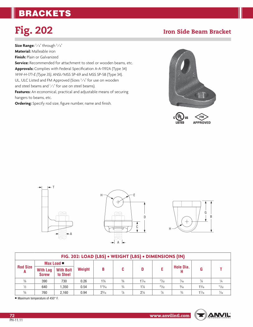
BRACKETS
www.anvilintl.com72
Fig. 202 Iron Side Beam Bracket
Size Range: 3⁄8" through 5⁄8"Material: Malleable ironFinish: Plain or GalvanizedService: Recommended for attachment to steel or wooden beams, etc.Approvals: Complies with Federal Specification A-A-1192A (Type 34) WW-H-171-E (Type 35), ANSI/MSS SP-69 and MSS SP-58 (Type 34). UL, ULC Listed and FM Approved (Sizes 3⁄8" for use on wooden and steel beams and 1⁄2" for use on steel beams).Features: An economical, practical and adjustable means of securinghangers to beams, etc.Ordering: Specify rod size, figure number, name and finish.
FIG. 202: LOAD (LBS) • WEIGHT (LBS) • DIMENSIONS (IN)
Rod Size A
Max Load ■
Weight B C D E Hole Dia. H G TWith Lag
ScrewWith Bolt to Steel
3⁄8 390 730 0.26 13⁄8 5⁄8 17⁄16 17⁄32 7⁄16 7⁄8 1⁄41⁄2 640 1,350 0.54 113⁄16 3⁄4 17⁄8 21⁄32 9⁄16 13⁄16 11⁄32
5⁄8 760 2,160 0.94 23⁄16 7⁄8 21⁄8 7⁄8 3⁄4 17⁄16 7⁄16
■ Maximum temperature of 450° F.
B
H
G
A
H E
C
D
T
A
PH-11.11

BRACKETS
www.anvilintl.com 73
Copp
er Tu
bing
Ha
nger
sPi
pe R
ings
Clev
is Ha
nger
sSt
eel P
ipe
Clam
psSo
cket
Clam
psSt
ructu
ral
Attac
hmen
tsBr
acke
tsCe
iling
Plat
es&
Flan
ges
Conc
rete
Inse
rts&
Attac
hmen
tsHa
nger
Rods
Rod
Attac
hmen
tsBo
lts, N
uts,
Pins
& U
-Bol
tsBe
amCl
amps
Picto
rial
Tabl
e of C
onten
tsCP
VCPi
pe H
ange
rsGe
nera
lNo
tes
Fig. 206 Steel Side Beam Bracket
Size Range: 3⁄8" through 5⁄8"Material: Carbon steelFinish: Plain or GalvanizedService: Clip can be fastened to side of joist or wall to support hanger rod.Approvals: Complies with Federal Specification A-A-1192A (Type 34), WW-H-171-E (Type 35)and ANSI/MSS SP-69 and MSS SP-58 (Type 34). UL Listed and FM Approved (steel beam only).Ordering: Specify rod size, figure number, name and finish.
Fig. 207 Threaded Steel Side Beam Bracket
Size Range: 3⁄8" and 1⁄2"Material: Carbon steelFinish: Plain or GalvanizedService: Recommended for attachment to steel or wooden beams, etc.Approvals: Complies with Federal Specification A-A-1192A (Type 34), WW-H-171-E (Type 35),ANSI/MSS SP-69 and MSS SP-58 (Type 34). UL Listed (Sizes 3⁄8" and 1⁄2").FM Approved (Size 3⁄8" for use on steel beam only)Features: Threaded mounting bracket provides an economical, practical and adjustablemeans of securing hangers to beams.Ordering: Specify rod size, figure number, name and finish.
FIG. 207: LOAD (LBS) • WEIGHT (LBS) • DIMENSIONS (IN)
Rod Size A
Bolt Size
Max LoadWeightWith Lag
ScrewWith Bolt to Steel
3⁄83⁄8 400
620 0.171⁄2 560
1⁄21⁄2 650
1,150 0.425⁄8 850
FIG. 206: LOAD (LBS) • WEIGHT (LBS) • DIMENSIONS (IN)
Rod Size
A
Max LoadWeight (lbs). L B
Hole Size
HTWith Lag
ScrewWith Bolt to Steel
3⁄8650 1,150
0.4421⁄16 5⁄8
7⁄161⁄4
1⁄2 0.43 9⁄16
5⁄8 850 2,000 0.84 21⁄2 3⁄4 11⁄16 3/8
L
L
B
H
B
T
21⁄2
3⁄81⁄2" BOLT HOLE
1⁄2" THD. ROD
5⁄8" BOLT HOLE
11⁄411⁄815⁄8
13⁄8
13⁄4
11⁄415⁄16
3⁄8" BOLT HOLE
3⁄8" THD. ROD
1⁄2" BOLT HOLE
1
5⁄16 3⁄4
1⁄4
Fig. 207 3/8"
Fig. 207 1/2"
PH-11.11

BRACKETS
www.anvilintl.com74
Fig. 189 Straight Eye Socket
Size: 3⁄8"Material: Galvanized steelService: Attachment to structure to connect threaded hanger rod.Approvals: UL and ULC Listed, and FM Approved.Installation:
• Thread rod completely into hanger. Secure rod by tightening jam nut against bottom of hanger.• Secure hanger to structural member with recommended fasteners.
Features: • Pre-formed threads for easy rod assembly.
Ordering: Specify rod size, figure number and name.
FIG. 189: DIMENSIONS (IN)A B
2.28 1.10
Description Pipe Sizes Rod Size Max. LoadStraight Eye Socket Hanger 3⁄4 " - 4" 3/8-16 UNC 250 lbs.
Notes: 1. For fire protection installation follow the requirements of National Fire
Protection Association, NFPA-13 and local codes.2. To assure proper performance, installer is responsible for: a. Structural integrity of attachment member to safely handle load
requirements. b. Securely tightening jam nut on the hanger rod.
FASTENERSDescription Quantity Pipe Size
#14 x 2" Wood Screw 2 * 3⁄4 " - 2"1⁄2 " x 3" Lag Screw *1 3⁄4 " - 4"
3/8-16 UNC Jam Nut 1 3⁄4 " - 4"
* Lag screw not required for 3/4" - 2" pipe sizes using the alternate option of (2) wood screws.
PH-11.11

BRACKETS
www.anvilintl.com 75
Copp
er Tu
bing
Ha
nger
sPi
pe R
ings
Clev
is Ha
nger
sSt
eel P
ipe
Clam
psSo
cket
Clam
psSt
ructu
ral
Attac
hmen
tsBr
acke
tsCe
iling
Plat
es&
Flan
ges
Conc
rete
Inse
rts&
Attac
hmen
tsHa
nger
Rods
Rod
Attac
hmen
tsBo
lts, N
uts,
Pins
& U
-Bol
tsBe
amCl
amps
Picto
rial
Tabl
e of C
onten
tsCP
VCPi
pe H
ange
rsGe
nera
lNo
tes
Fig. 190 Off-Set Eye Socket
Size: 3⁄8"Material: Galvanized steelService: Attachment to structure to connect threaded hanger rod.Approvals: UL and ULC Listed, and FM Approved.Installation:
• Thread rod completely into hanger. Secure rod by tightening jam nut against bottom of hanger.• Secure hanger to structural member with recommended fasteners.
Features: • Pre-formed threads for easy rod assembly.• Off-set angle provides unlimited vertical adjustment.
Ordering: Specify rod size, figure number and name.
FIG. 190: DIMENSIONS (IN)A B
3.38 1.10
Description Pipe Sizes Rod Size Max. LoadOff-Set Eye Socket Hanger 3⁄4 " - 4" 3/8-16 UNC 250 lbs.
Notes: 1. For fire protection installation follow the requirements of National Fire
Protection Association, NFPA-13 and local codes.2. To assure proper performance, installer is responsible for: a. Structural integrity of attachment member to safely handle load
requirements. b. Securely tightening jam nut on the hanger rod.
FASTENERSDescription Quantity Pipe Size
#14 x 2" Wood Screw 2 * 3⁄4 " - 2"1⁄2 " x 3" Lag Screw *1 3⁄4 " - 4"
3/8-16 UNC Jam Nut 1 3⁄4 " - 4"
* Lag screw not required for 3/4" - 2" pipe sizes using the alternate option of (2) wood screws.
PH-11.11

BRACKETS
www.anvilintl.com76
Fig. 194 Light Welded Steel Bracket
Material: Carbon steelFinish: Plain or GalvanizedService: Recommended for support from below or above bracket.Approvals: Complies with Federal Specification A-A-1192A (Type 31), WW-H-171-E (Type 32), ANSI/MSS SP-69 and MSS SP-58 (Type 31). FM Approved when used with 3⁄8" rod, 3⁄4" - 4" pipe sizes & 1⁄2" rod, 5" - 8" pipe sizes.How to size: Determine bracket size by dimension of standard bracket most suitable to the installation.Installation: When bolted to a wall, an additional back plate may be required of such thickness and size as to properly distribute the weight over the wall. Size and thickness of the back plate is governed by the load to be carried and the nature and conditions of the wall. Back plates furnished upon request.Features:
• Bracket may be installed either in position illustrated or reversed.• Ends of bracket are drilled to accept hanger rods up to 3⁄4".
Ordering: Specify bracket number, figure number, name and finish.Order separately: Hanger rods, 2 bolts and plate washers are available through our Regional Service Centers, order as a Figure 193.
FIG. 194: LOAD (LBS) • WEIGHT (LBS) • DIMENSIONS (IN)Bracket no. Max Load Weight W C D
1
750
3.1 9 61⁄25⁄16
2 7.7 13 101⁄2
3 12.8 19 161⁄2 3⁄8
13⁄16 Max 3⁄4"
13⁄16
W1"
2"1"
D
W C
Additional Rod Attachments Available.Requires: 2 bolts, 2 plate washers (not included)
PH-11.11

BRACKETS
www.anvilintl.com 77
Copp
er Tu
bing
Ha
nger
sPi
pe R
ings
Clev
is Ha
nger
sSt
eel P
ipe
Clam
psSo
cket
Clam
psSt
ructu
ral
Attac
hmen
tsBr
acke
tsCe
iling
Plat
es&
Flan
ges
Conc
rete
Inse
rts&
Attac
hmen
tsHa
nger
Rods
Rod
Attac
hmen
tsBo
lts, N
uts,
Pins
& U
-Bol
tsBe
amCl
amps
Picto
rial
Tabl
e of C
onten
tsCP
VCPi
pe H
ange
rsGe
nera
lNo
tes
Fig. 195 Medium Welded Steel Bracket
Material: Carbon steelFinish: Plain or GalvanizedService: Recommended for the support of loads from below or above bracket.Approvals: Complies with Federal Specification A-A-1192A (Type 32), WW-H-171-E (Type 33), ANSI/MSS SP-69 and MSS SP-58 (Type 32).How to size: Determine size by dimensions most suitable to the installation (see dimensions of standard brackets below). Special welded steel brackets can be furnished on order.Installation: When bolted to a wall, an additional back plate may be required of such thickness and size as to properly distribute the weight over the wall. Size and thickness of the back plate is governed by the load to be carried and the nature and conditions of the wall. Back plates furnished upon request.Features: If supporting pipe by rod, rod can be installed anywhere along the length of the bracket thus providing horizontal adjustment.Ordering: Specify bracket number, figure number, name and finish. Orders for special brackets are to be accompanied by detailed sketch.Order Separately: Rod, Fig. 60, bolts, nuts, and back plates for fastening brackets to wall. Specify size and length of rod, bolts size, thickness, and drilling of back plates.
FIG. 195: LOAD (LBS) • WEIGHT (LBS) • DIMENSIONS (IN)Bracket no. Max Load Weight W B C F G H
0
1,500
17.4 12 18 151⁄2 4 11⁄2 11⁄2
1 27.3 18 24 211⁄25
13⁄4 13⁄4
2 47.7 24 30 271⁄2 2 2
W
Fig. 6021⁄2"11⁄4"
3⁄8"
13⁄16"
FG
B C
H
1" GAP
PH-11.11

BRACKETS
www.anvilintl.com78
Fig. 199 Heavy Welded Steel Bracket
Material: Carbon steelFinish: Plain or GalvanizedService: Recommended for the support of loads from above or below bracket.Approvals: Complies with Federal Specification A-A-1192A (Type 33) WW-H-171-E (Type 34), ANSI/MSS SP-69 and MSS SP-58 (Type 33).How to size: Determine size by dimensions most suitable to the installation (see dimensions of standard brackets below). Special welded steel bracketscan be furnished on order.Installation: When bolted to a wall, an additional back plate may be required of such thickness and size as to properly distribute the weight over the wall. Size and thickness of the back plate is governed by the load to be carried and the nature and conditions of the wall. Back plates furnished upon request.Features: If supporting pipe by rod, rod can be installed at any point along the length of the bracket thus providing horizontal adjustment.Ordering: Specify bracket number, figure number, name. Orders for special brackets are to be accompanied by detailed sketch.Order Separately: Rod, Fig. 60, bolts, nuts, and back plates for fastening brackets to wall. Specify size and length of rod, bolts size, thickness, and drilling of back plates.
FIG. 199: LOAD (LBS) • WEIGHT (LBS) • DIMENSIONS (IN)Bracket no. Max Load Weight W B C D E F G H K L
0
3,000
24.3 12 18 151⁄4 13⁄823⁄4
4 11⁄42
– 13⁄16
1 51.8 18 24 213⁄8 17⁄16
5 223⁄4 15⁄16
2 68.9 24 30 271⁄2 11⁄221⁄2 21⁄2
11⁄163 86.1 30 36 331⁄4 15⁄8
34 140.5 36 42 39
11⁄2 6 21⁄2 31⁄2 31⁄25 166.4 42 50 46 31⁄2
Fig. 60
1⁄2"W
ED
F F
KG
B C B C
HOLEDIA (L)
HOLEDIA (L)
H
G
H
1" GAP1" GAP
PH-11.11
Bracket Number 0 Bracket Number 1-5
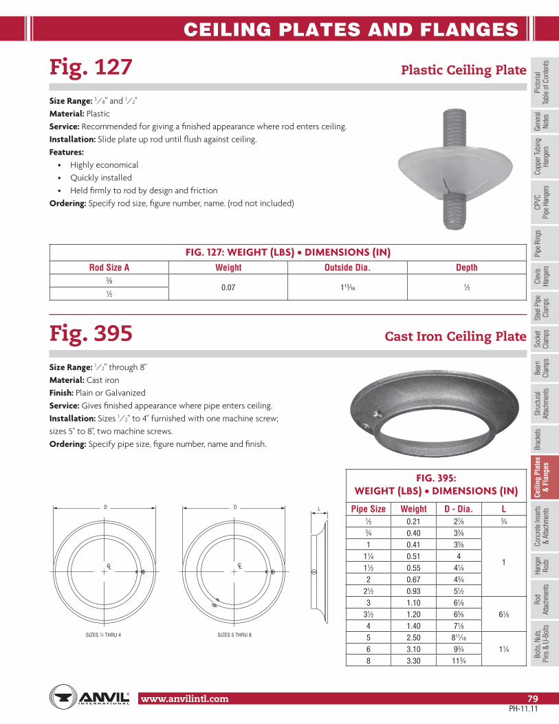
CEILING PLATES AND FLANGES
www.anvilintl.com 79
Copp
er Tu
bing
Ha
nger
sPi
pe R
ings
Clev
is Ha
nger
sSt
eel P
ipe
Clam
psSo
cket
Clam
psSt
ructu
ral
Attac
hmen
tsBr
acke
tsCe
iling
Pla
tes
& F
lang
esCo
ncre
te In
serts
& At
tachm
ents
Hang
erRo
dsRo
d At
tachm
ents
Bolts
, Nut
s,Pi
ns &
U-B
olts
Beam
Clam
psPi
ctoria
lTa
ble o
f Con
tents
CPVC
Pipe
Han
gers
Gene
ral
Notes
Fig. 127 Plastic Ceiling Plate
Size Range: 3⁄8" and 1⁄2"Material: PlasticService: Recommended for giving a finished appearance where rod enters ceiling.Installation: Slide plate up rod until flush against ceiling.Features:
• Highly economical• Quickly installed• Held firmly to rod by design and friction
Ordering: Specify rod size, figure number, name. (rod not included)
Fig. 395 Cast Iron Ceiling Plate
Size Range: 1⁄2" through 8"Material: Cast ironFinish: Plain or GalvanizedService: Gives finished appearance where pipe enters ceiling.Installation: Sizes 1⁄2" to 4" furnished with one machine screw; sizes 5" to 8", two machine screws.Ordering: Specify pipe size, figure number, name and finish.
FIG. 127: WEIGHT (LBS) • DIMENSIONS (IN)Rod Size A Weight Outside Dia. Depth
3⁄80.07 113⁄16 1⁄2
1⁄2
FIG. 395: WEIGHT (LBS) • DIMENSIONS (IN)
Pipe Size Weight D - Dia. L1⁄2 0.21 27⁄8 3⁄43⁄4 0.40 33⁄8
1
1 0.41 35⁄811⁄4 0.51 411⁄2 0.55 41⁄42 0.67 43⁄4
21⁄2 0.93 51⁄23 1.10 61⁄8
61⁄831⁄2 1.20 65⁄84 1.40 71⁄85 2.50 811⁄16
11⁄46 3.10 93⁄48 3.30 113⁄4
LDD
SIZES 1⁄2 8 URHT 5 SEZIS4 URHT
CL CL
PH-11.11

CEILING PLATES AND FLANGES
www.anvilintl.com80
Fig. 128R Rod Threaded, Ceiling Flange
Size Range: 3⁄8" and 1⁄2"Material: Malleable ironFinish: Plain or GalvanizedService: Recommended for attachment to wood beams or ceiling.Ordering: Specify rod size, figure number, name and finish.
FIG. 128R: LOAD (LBS) • WEIGHT (LBS) • DIMENSIONS (IN)
Rod Size A
Max Load Weight
Screws (not included)Quantity Size No.
3⁄8180 0.16 2 12
1⁄2
A
21⁄4"
13⁄8"
35⁄16"
1⁄2"
3⁄16"
PH-11.11

CEILING PLATES AND FLANGES
www.anvilintl.com 81
Copp
er Tu
bing
Ha
nger
sPi
pe R
ings
Clev
is Ha
nger
sSt
eel P
ipe
Clam
psSo
cket
Clam
psSt
ructu
ral
Attac
hmen
tsBr
acke
tsCe
iling
Pla
tes
& F
lang
esCo
ncre
te In
serts
& At
tachm
ents
Hang
erRo
dsRo
d At
tachm
ents
Bolts
, Nut
s,Pi
ns &
U-B
olts
Beam
Clam
psPi
ctoria
lTa
ble o
f Con
tents
CPVC
Pipe
Han
gers
Gene
ral
Notes
Fig. 153 Pipe Hanger Flange
Size Range: 3⁄8" through 3⁄4"Material: Malleable ironFinish: PlainService: Recommended for suspension of pipe lines or conduit from level ceilings.Approvals: UL, ULC Listed and FM Approved (Sizes 3⁄8" and 1⁄2").Installation: Flange size 3⁄8" has two holes, sizes 1⁄2", 5⁄8", and 3⁄4" have three holes.Features:
• Provides vertical adjustment up to 1".• Good appearance.
Ordering: Specify rod size, figure number and name.
FIG. 153: LOAD (LBS) • WEIGHT (LBS) • DIMENSIONS (IN)
Rod Size A Max Load Weight Size Screw “H”
(not included) B C D E Screw Circle Dia. – F
3⁄8 425 0.4 #18 x 11⁄2 27⁄8 13⁄8 7⁄8 3⁄16 21⁄2 1,050 0.9 3⁄8 x 2 4 11⁄2 15⁄16 1⁄4 27⁄85⁄8 1,220 1.5 1⁄2 x 2 43⁄4 15⁄8 1 5⁄16 33⁄83⁄4 1,270 2.2 9⁄16 x 2 51⁄4 17⁄8 11⁄16 3⁄8 35⁄8
A
B
H (3 PLACES)
H (2 PLACES)
F
ED
C
F
3⁄8" Size 1⁄2", 5⁄8", 3⁄4" Size
PH-11.11

CONCRETE INSERTS & ATTACHMENTS
www.anvilintl.com82
Fig. 152 Screw Concrete Insert
Size Range: 3⁄8" through 7⁄8"Material: Malleable ironFinish: PlainService: Upper attachment for suspending pipe from a concrete ceiling where no lateral adjustment is required.Approvals: UL, ULC Listed and FM Approved.Features:
• Eliminates the necessity of drilling holes in wooden forms.• Reduced overall height and four slots for nail attachment gives stability to the insert while the concrete is being poured.
Ordering: Specify rod size, figure number and name.
FIG. 152: LOAD (LBS) • WEIGHT (LBS) • DIMENSIONS (IN)
Rod Size A Max Load ■ Weight B C D E E’ F
3⁄8 730 0.3111⁄32
21⁄4 11⁄2
3⁄8 15⁄81⁄2 1,130 0.32
5⁄8 1,260 0.37 17⁄32 5⁄8
3⁄42,500
0.6415⁄8 21⁄2 11⁄4
15⁄16 7⁄16
27⁄8 0.71 1 3⁄8
■ Based on insert only. Rating is subject to the condition that the concrete used is of sufficient strength to hold the insert.
AD
E
E'CB
F
PH-11.11

CONCRETE INSERTS & ATTACHMENTS
www.anvilintl.com 83
Copp
er Tu
bing
Ha
nger
sPi
pe R
ings
Clev
is Ha
nger
sSt
eel P
ipe
Clam
psSo
cket
Clam
psSt
ructu
ral
Attac
hmen
tsBr
acke
tsCe
iling
Plat
es&
Flan
ges
Conc
rete
Inse
rts&
Atta
chm
ents
Hang
erRo
dsRo
d At
tachm
ents
Bolts
, Nut
s,Pi
ns &
U-B
olts
Beam
Clam
psPi
ctoria
lTa
ble o
f Con
tents
CPVC
Pipe
Han
gers
Gene
ral
Notes
Fig. 282 Universal Concrete Insert
Size Range: 3⁄8" through 7⁄8"Material: Malleable iron body and nutFinish: Plain or GalvanizedService: Upper attachment for suspending pipe, shafting, motors and similar equipment from a concrete ceiling; especially suitable where rod sizes cannot bereadily determined in advance.Approvals: Complies with Federal Specification A-A-1192A (Type 18), WW-H-171-E (Type 18),ANSI/MSS SP-69 and MSS SP-58 (Type 18). UL, ULC Listed and FM Approved.Installation:
1. Nail insert to wooden forms.2. Where convenient, reinforcing rods may be placed in the opening through the top of the insert, or short lengths of reinforcing rod may be wired to the insert prior to pouring concrete. However, the specified load ratings and approvals are not dependent on the use of any reinforcing rods in contact with the insert.3. After concrete is poured and wooden forms are removed, place nut in insert and screw rod through nut until rod is firmly against the top of the insert body. The rod should not be forced against the top of the recess thereby placing unnecessary stress at the opening of the insert by the nut.
Features:• Cast body prevents concrete seepage.• Opening in top of insert provides for use of reinforcing rods up to 7⁄8" diameter. Sides of insert are recessed for reinforcing rods up to 1" diameter.• Low height, broad flat bottom and widely separated nail slots minimize displacement during construction.• The nut, held in place by V-type teeth on both insert and nut, can be raised and moved from side to side providing for lateral adjustment.• Rod is locked in place by screwing it firmly against the top of the recess.• One body size.
Ordering: Specify figure number, name, finish and size of nut.
FIG. 282: LOAD (LBS) • WEIGHT (LBS) • DIMENSIONS (IN)
Rod Size A
Adjustment B
Max Load ■ Weight
Insert Complete With Nut
3⁄8
111⁄16
730
1.5
1⁄2 1,1305⁄8 1,1403⁄4 1,1407⁄8 11⁄8 1,140
Insert Only – – – 1.3
Nut Only
3⁄8 – –
0.2
1⁄2 – –5⁄8 – –3⁄4 – –7⁄8 – –
■ Based on insert and nut only. Rating is subject to the condition that the concrete used is of sufficient strength to hold the insert.
33⁄8 17⁄831⁄4
23⁄1613⁄16
B
AA
PH-11.11
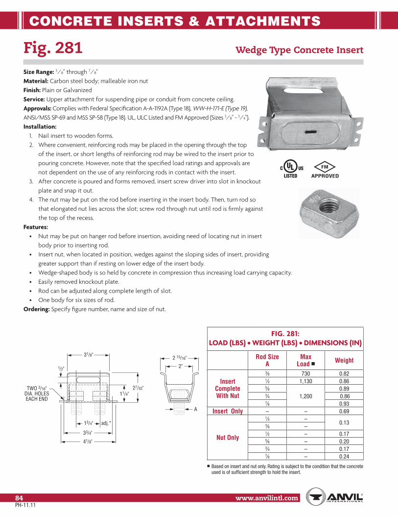
CONCRETE INSERTS & ATTACHMENTS
www.anvilintl.com84
Fig. 281 Wedge Type Concrete Insert
Size Range: 3⁄8" through 7⁄8"Material: Carbon steel body; malleable iron nutFinish: Plain or GalvanizedService: Upper attachment for suspending pipe or conduit from concrete ceiling.Approvals: Complies with Federal Specification A-A-1192A (Type 18), WW-H-171-E (Type 19),ANSI/MSS SP-69 and MSS SP-58 (Type 18). UL, ULC Listed and FM Approved (Sizes 3⁄8" - 3⁄4").Installation:
1. Nail insert to wooden forms.2. Where convenient, reinforcing rods may be placed in the opening through the top of the insert, or short lengths of reinforcing rod may be wired to the insert prior to pouring concrete. However, note that the specified load ratings and approvals are not dependent on the use of any reinforcing rods in contact with the insert.3. After concrete is poured and forms removed, insert screw driver into slot in knockout plate and snap it out.4. The nut may be put on the rod before inserting in the insert body. Then, turn rod so that elongated nut lies across the slot; screw rod through nut until rod is firmly against the top of the recess.
Features:• Nut may be put on hanger rod before insertion, avoiding need of locating nut in insert body prior to inserting rod.• Insert nut, when located in position, wedges against the sloping sides of insert, providing greater support than if resting on lower edge of the insert body.• Wedge-shaped body is so held by concrete in compression thus increasing load carrying capacity.• Easily removed knockout plate.• Rod can be adjusted along complete length of slot.• One body for six sizes of rod.
Ordering: Specify figure number, name and size of nut.
FIG. 281: LOAD (LBS) • WEIGHT (LBS) • DIMENSIONS (IN)
Rod Size A
Max Load ■ Weight
Insert Complete With Nut
3⁄8 730 0.821⁄2 1,130 0.865⁄8
1,2000.89
3⁄4 0.867⁄8 0.93
Insert Only – – 0.69
Nut Only
1⁄4 –0.133⁄8 –
1⁄2 – 0.175⁄8 – 0.203⁄4 – 0.177⁄8 – 0.24
■ Based on insert and nut only. Rating is subject to the condition that the concrete used is of sufficient strength to hold the insert.
31/8"
1/2"
11/4"27/32"
13/4" adj.*
33/4"
41/8"
TWO 3/16"DIA. HOLESEACH END
2 15/16"
2"
A
PH-11.11

CONCRETE INSERTS & ATTACHMENTS
www.anvilintl.com 85
Copp
er Tu
bing
Ha
nger
sPi
pe R
ings
Clev
is Ha
nger
sSt
eel P
ipe
Clam
psSo
cket
Clam
psSt
ructu
ral
Attac
hmen
tsBr
acke
tsCe
iling
Plat
es&
Flan
ges
Conc
rete
Inse
rts&
Atta
chm
ents
Hang
erRo
dsRo
d At
tachm
ents
Bolts
, Nut
s,Pi
ns &
U-B
olts
Beam
Clam
psPi
ctoria
lTa
ble o
f Con
tents
CPVC
Pipe
Han
gers
Gene
ral
Notes
Fig. 285 Light Weight Concrete Insert
Size Range: 1⁄4" through 5⁄8"Material: Carbon steelFinish: Plain or GalvanizedService: Upper attachment for suspending pipe or conduit from concrete ceiling.Approvals: Complies with Federal Specification A-A-1192A (Type 18), WW-H-171-E (Type 18), ANSI/MSS SP-69 and MSS SP-58 (Type 19). UL, ULC Listed (Sizes 3⁄8" - 5⁄8") and FM Approved (Sizes 3⁄8" and 1⁄2").Installation:
1. Nail insert to wooden forms.2. Reinforcing rods may be located under the arched flanges at the top of the insert. However, note that the specified load ratings and approvals are not dependent on the use of any reinforcing rods in contact with the insert.3. After concrete is poured and wooden forms are removed, remove knockout by tapping along edge with pointed instrument.4. Slip nut into insert and screw rod through nut until rod is firmly against the top of the insert body.
Features:• Suitable for use in concrete 2" thick due to low overall height.• Highly competitive.• Provides for 2" of lateral adjustment.• Knockout prevents seepage of concrete from underneath the insert up into the insert body.• One body size.• Removable nut in four sizes.• Rod can be rigidly locked in position.
Ordering: Specify figure number, name, finish and size of nut.
FIG. 285:LOAD (LBS) • WEIGHT (LBS) • DIMENSIONS (IN)
Rod Size A
Max Load ■ Weight
Insert Complete With Nut
1⁄4 230 0.463⁄8
4000.49
1⁄2 0.495⁄8 0.48
Insert Only – – 0.41
Nut Only
1⁄4 –
0.073⁄8 –1⁄2 –5⁄8 –
■ Based on insert and nut only. Rating is subject to the condition that the concrete used is of sufficient strength to hold the insert.
33/4"
2" ADJ.
41/4"
1"
A
11/4"
TWO 5/32"DIA. HOLESEACH END
21/2"11/4"
PH-11.11
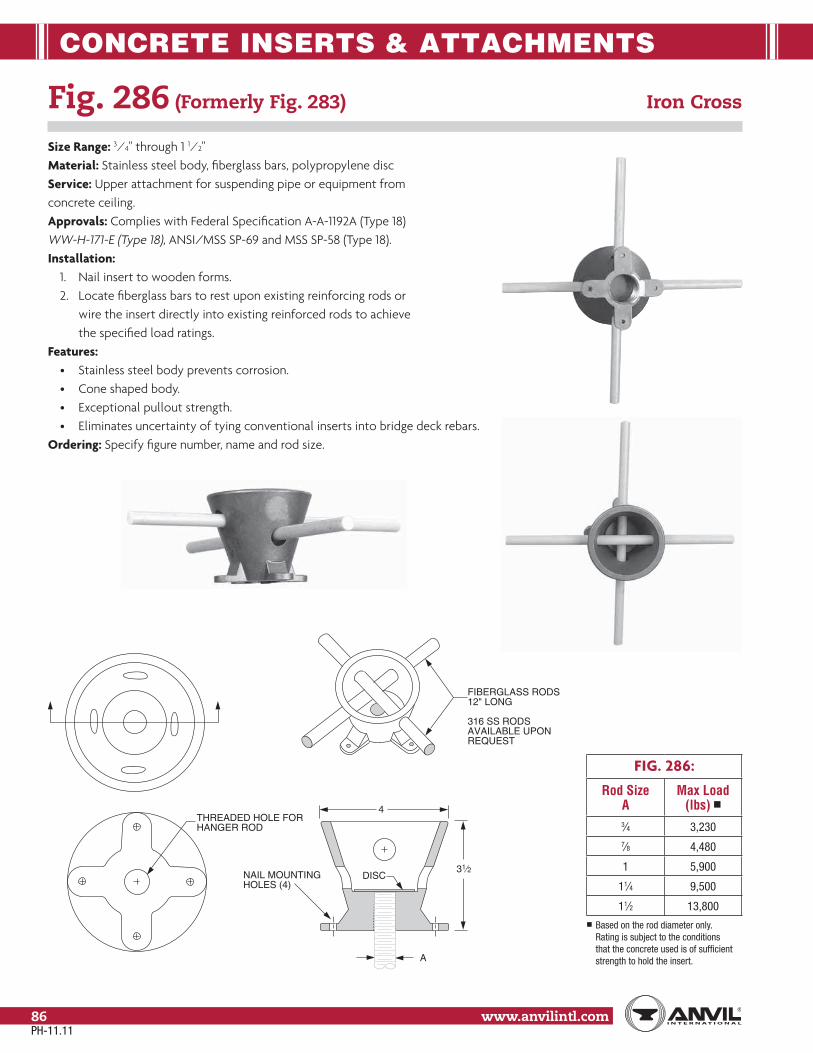
CONCRETE INSERTS & ATTACHMENTS
www.anvilintl.com86
Fig. 286 (Formerly Fig. 283) Iron Cross
Size Range: 3⁄4" through 1 1⁄2"Material: Stainless steel body, fiberglass bars, polypropylene discService: Upper attachment for suspending pipe or equipment from concrete ceiling.Approvals: Complies with Federal Specification A-A-1192A (Type 18) WW-H-171-E (Type 18), ANSI/MSS SP-69 and MSS SP-58 (Type 18).Installation:
1. Nail insert to wooden forms.2. Locate fiberglass bars to rest upon existing reinforcing rods or wire the insert directly into existing reinforced rods to achieve the specified load ratings.
Features:• Stainless steel body prevents corrosion.• Cone shaped body.• Exceptional pullout strength.• Eliminates uncertainty of tying conventional inserts into bridge deck rebars.
Ordering: Specify figure number, name and rod size.
FIG. 286:
Rod Size A
Max Load (lbs) ■
3⁄4 3,2307⁄8 4,480
1 5,900
11⁄4 9,500
11⁄2 13,800■ Based on the rod diameter only.
Rating is subject to the conditions that the concrete used is of sufficient strength to hold the insert.
4
A
31⁄2
THREADED HOLE FORHANGER ROD
FIBERGLASS RODS12" LONG
316 SS RODSAVAILABLE UPONREQUEST
NAIL MOUNTINGHOLES (4)
DISC
PH-11.11
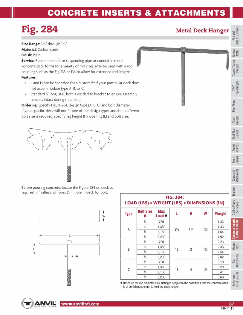
CONCRETE INSERTS & ATTACHMENTS
www.anvilintl.com 87
Copp
er Tu
bing
Ha
nger
sPi
pe R
ings
Clev
is Ha
nger
sSt
eel P
ipe
Clam
psSo
cket
Clam
psSt
ructu
ral
Attac
hmen
tsBr
acke
tsCe
iling
Plat
es&
Flan
ges
Conc
rete
Inse
rts&
Atta
chm
ents
Hang
erRo
dsRo
d At
tachm
ents
Bolts
, Nut
s,Pi
ns &
U-B
olts
Beam
Clam
psPi
ctoria
lTa
ble o
f Con
tents
CPVC
Pipe
Han
gers
Gene
ral
Notes
Fig. 284 Metal Deck Hanger
Size Range: 3⁄8" through 3⁄4"Material: Carbon steelFinish: PlainService: Recommended for suspending pipe or conduit in metal concrete deck forms for a variety of rod sizes. May be used with a rod coupling such as the Fig. 135 or 136 to allow for extended rod lengths.Features:
• L and H can be specified for a custom fit if your particular deck does not accommodate type A, B, or C.• Standard 6" long UNC bolt is welded to bracket to ensure assembly remains intact during shipment.
Ordering: Specify Figure 284, design type (A, B, C) and bolt diameter. If your specific deck will not fit one of the design types and/or a different bolt size is required, specify leg height (H), opening (L) and bolt size.
FIG. 284: LOAD (LBS) • WEIGHT (LBS) • DIMENSIONS (IN)
Type Bolt Size A
MaxLoad ■ L H W Weight
A
3⁄8 730
95⁄8 13⁄4 11⁄2
1.331⁄2 1,350 1.435⁄8 2,160 1.643⁄4 3,230 1.92
B
3⁄8 730
12 3 11⁄2
2.231⁄2 1,350 2.335⁄8 2,160 2.543⁄4 3,230 2.82
C
3⁄8 730
16 4 11⁄2
3.101⁄2 1,350 3.205⁄8 2,160 3.413⁄4 3,230 3.69
■ Based on the rod diameter only. Rating is subject to the conditions that the concrete used is of sufficient strength to hold the deck hanger.
A
L
H
W
Before pouring concrete, locate the Figure 284 on deck so legs rest in "valleys" of form. Drill hole in deck for bolt.
PH-11.11

CONCRETE INSERTS & ATTACHMENTS
www.anvilintl.com88
Fig. 47 Concrete Single Lug Plate
Size Range: 1⁄2" through 2"Material: Carbon steelFinish: Plain or GalvanizedService: Structural attachment to concrete ceiling lug is used in conjunction with Fig. 299 (see page 98) forged steel clevis and anchors of sufficient strength to hold the desired load.Ordering: Specify rod size, figure number, name and finish.
FIG. 47: LOAD (LBS) • WEIGHT (LBS) • DIMENSIONS (IN)
Rod Size A
Max Load ■ Weight J B C D E F G H R T U
1⁄2 1,350 11.1
1
8
10 5
47⁄8 9⁄16
3⁄8
11⁄211⁄4
1⁄45⁄8
5⁄8 2,160 14.61⁄2
3⁄43⁄4 3,230 14.8
413⁄16 11⁄16 3⁄87⁄8
7⁄8 4,480 22.03⁄4 2
1
1 5,900 31.9
2 12 6
53⁄4 13⁄16 11⁄2 1⁄2 11⁄8
11⁄4 9,500 43.8 511⁄16 15⁄161
3
2 5⁄8 13⁄8
11⁄2 13,800 45.6
55⁄8
11⁄821⁄2
3⁄4
15⁄8
13⁄4 18,600 55.713⁄8 11⁄4
17⁄8
2 24,600 58.2 4 3 21⁄4■ Based on the rod diameter only. Rating is subject to the conditions that the concrete and anchors used are of sufficient strength to hold the load.
D
G
R U (pin dia.)
H
E
CB
T
J
J
B
C
F Dia.(4 Places)
PH-11.11

CONCRETE INSERTS & ATTACHMENTS
www.anvilintl.com 89
Copp
er Tu
bing
Ha
nger
sPi
pe R
ings
Clev
is Ha
nger
sSt
eel P
ipe
Clam
psSo
cket
Clam
psSt
ructu
ral
Attac
hmen
tsBr
acke
tsCe
iling
Plat
es&
Flan
ges
Conc
rete
Inse
rts&
Atta
chm
ents
Hang
erRo
dsRo
d At
tachm
ents
Bolts
, Nut
s,Pi
ns &
U-B
olts
Beam
Clam
psPi
ctoria
lTa
ble o
f Con
tents
CPVC
Pipe
Han
gers
Gene
ral
Notes
Fig. 49 Concrete Clevis Plate
Size Range: 3⁄8" through 1 3⁄4"Material: Carbon steelFinish: Plain or GalvanizedService: Structural attachment to concrete ceiling whereflexibility is desired. Concrete clevis plate is normally usedin conjunction with Fig. 290, page 97, weldless eye nut, orFig. 278, page 93 welded eye rod and anchors of sufficientstrength to hold the desired load.Ordering: Specify rod size, figure number, name and finish.Note: Sizes 3⁄8" through 1" are supplied with bolt and nut.Larger sizes are supplied with pin and cotters.
FIG. 49: LOAD (LBS) • WEIGHT (LBS) • DIMENSIONS (IN)
Rod Size A
Max Load ■ Weight J B C D F G H R S T U W
3⁄8 730 11.8
1
8
10 5
9⁄16
3⁄8
27⁄8 11⁄4 1⁄4
1⁄2
21⁄2 1,350 11.9 5⁄85⁄8 2,160 15.7
1⁄2
3⁄43⁄4 3,230 16.9
11⁄1611⁄8 17⁄8
3⁄87⁄8
21⁄27⁄8 4,480 18.1 3 11⁄4 2 1
1 5,900 36.9
212 6
13⁄163⁄4 3
11⁄221⁄2
1⁄2 11⁄8 3
11⁄4 9,500 40.9 15⁄16 2 5⁄8 13⁄8 4
11⁄2 13,800 59.8 11⁄8 1 4 21⁄2 3 3⁄4 15⁄85
13⁄4 18,600 93.6 10 14 7 13⁄8 11⁄4 5 23⁄4 31⁄2 1⁄2 17⁄8
■ Based on the rod diameter only. Rating is subject to the conditions that the concrete and anchors used are of sufficient strength to hold the load.
F (4 PLACES)
B C
C
B J
J
D
H
G
R
WU
D
(Pin or Bolt Size)S T
PH-11.11

CONCRETE INSERTS & ATTACHMENTS
www.anvilintl.com90
Fig. 52 Concrete Rod Attachment Plate
Size Range: 3⁄8" through 1 1⁄4"Material: Carbon steelFinish: Plain or GalvanizedService: Structural attachment to concrete ceiling where vertical adjustment is desired. Normally used with threaded rod and nut and anchors of sufficient strength to hold the desired load.Ordering: Specify rod size, figure number, name and finish.
FIG. 52: LOAD (LBS) • WEIGHT (LBS) • DIMENSIONS (IN)
Rod Size A
Max Load ■ Weight J B C D E F H G
3⁄8 730 11.6
1
8
10 5
21⁄49⁄16 27⁄8
3⁄81⁄2 1,350 11.6 21⁄85⁄8 2,160 15.1
21⁄41⁄23⁄4 3,230 16.1
11⁄1631⁄8
7⁄8 4,480 16.7 31⁄8 41⁄4
1 5,900 34.92 12 6
31⁄2 13⁄16 41⁄23⁄4
11⁄4 9,500 40.9 35⁄8 15⁄16 5■ Based on the rod diameter only. Rating is subject to the conditions that the concrete and anchors used are of sufficient strength to hold the load.
A
E
F (4 PLACES)
B C
C
B J
J
D
H
G
D
PH-11.11

HANGER RODS
www.anvilintl.com 91
Copp
er Tu
bing
Ha
nger
sPi
pe R
ings
Clev
is Ha
nger
sSt
eel P
ipe
Clam
psSo
cket
Clam
psSt
ructu
ral
Attac
hmen
tsBr
acke
tsCe
iling
Plat
es&
Flan
ges
Conc
rete
Inse
rts&
Attac
hmen
tsHa
nger
Rods
Rod
Attac
hmen
tsBo
lts, N
uts,
Pins
& U
-Bol
tsBe
amCl
amps
Picto
rial
Tabl
e of C
onten
tsCP
VCPi
pe H
ange
rsGe
nera
lNo
tes
Fig. 142 Coach Screw Rods Machine Threaded on Opposite End
Size Range: 3⁄8" and 1⁄2"Material: Carbon steelFinish: PlainOrdering: Specify rod size, figure number, name and rod length.
Fig. 146 Continuous Threaded Rod
Size Range: 1⁄4" through 1 1⁄2" Stocked in six, ten, and twelve foot lengths. Other even foot lengths can be furnished to order.Material: Carbon steel or Stainless Steel Gr 304Threads: National Coarse (USS), rod threaded complete length.Finish: Plain or Galvanized.Maximum Temperature: 650° F.Ordering: Specify rod diameter and length, figure number, name and finish.Note: The acceptability of galvanized coatings at temperatures above 450°F is at the discretion of the end user.
FIG. 146: LOADS (LBS) • WEIGHTS (LBS) • DIMENSIONS (IN)
Rod Size A
Threads per Inch
Max Load Weight per Ft.650˚ F
1⁄4 20 240 0.123⁄8 16 730 0.301⁄2 13 1,350 0.535⁄8 11 2,160 0.843⁄4 10 3,230 1.207⁄8 9 4,480 1.701 8 5,900 2.30
11⁄4 7 9,500 3.6011⁄2 6 13,800 5.10
Note: Other rod sizes available upon request. Class 2 fit is available upon request.
FIG. 142: STANDARD THREAD LENGTHS (IN) • LOADS (LBS)
Rod Size A
Standard Length - L
Coach Screw Thread Length – C
Standard Rod Thread Length – D
Max Load
3⁄831⁄2
23⁄4
3908 21⁄2
1⁄231⁄2
27⁄16
3⁄4640
8 21/2
A DC
L
A
Length
PH-11.11

HANGER RODS
www.anvilintl.com92
Fig. 140: Right-hand Threads Machine Threaded Rods Threaded Both EndsFig. 253: Right and Left hand Threads
Size Range: 3⁄8" through 5"Material: Carbon steelFinish: Plain or GalvanizedOrdering: Specify rod size, figure number, name, rod length and finish. Specify thread length if other than standard.Note: The acceptability of galvanized coatings at temperatures above 450°F is at the discretion of the end user.
FIG. 140, 253: LOADS (LBS) • DIMENSIONS (IN)
Rod Size A
Threads per Inch
Max Load Standard Rod Thread Length D*650° F 750° F
3⁄8 16 730 572
21⁄21⁄2 13 1,350 1,0575⁄8 11 2,160 1,6923⁄4 10 3,230 2,530 37⁄8 9 4,480 3,508 31⁄2
1 8 5,900 4,620 4
11⁄4 7 9,500 7,440 5
11⁄2 6 13,800 10,807 6
13⁄4 5 18,600 14,566 7
2 41⁄2 24,600 19,265 8
21⁄4 41⁄2 32,300 25,295 9
21⁄2 4 39,800 31,169 10
FIG. 140, 253: LOADS (LBS) • DIMENSIONS (IN) (CONT.)
Rod Size A
Threads per Inch
Max Load Standard Rod Thread Length D*650° F 750° F
23⁄4 4 49,400 38,687 113 4 60,100 47,066 12
31⁄4 4 71,900 56,307 1331⁄2 4 84,700 66,331 1433⁄4 4 98,500 77,139
154 4 113,400 88,807
41⁄4 4 UN 129,400 101,337
1841⁄2 4 UN 146,600 114,80743⁄4 4 UN 164,700 128,9825 4 UN 184,000 144,096
* Fig. 140 rod up to 1" rod size and 24" in length may be furnished as Fig 146 rod unless order states that all thread rod is not acceptable.
*3/8"- 4" Diameter: UNC-2A CLASS fit.
Fig. 248: Right Hand Threads Eye Rod Not Welded
Fig. 248L: Left Hand Threads
Size Range: 3⁄8" through 2 1⁄2"Material: Carbon steelFinish: Plain or Galvanized.Maximum Temperature: 650° FFeatures: Through 1 1⁄2", inside diameter of eye will accommodate a bolt diameter 1⁄8" larger than rod diameter; 1 3⁄4" and larger, inside diameter of eye will take a bolt diameter 1⁄4" larger than rod diameter.Ordering: Specify rod diameter, figure number, name, rod length and finish. Specify thread length if other than standard.
FIG. 248, FIG. 248L: LOADS (LBS) • DIMENSIONS (IN)
Rod Size A
Standard Rod Thread Length – D
L (min)
Max Load 650° F
3⁄821⁄2
41⁄4 2401⁄25⁄8 41⁄2 7053⁄4 3 51⁄2 1,0507⁄8 31⁄2 61⁄2 1,4701 4 71⁄4 1,940
11⁄4 5 81⁄4 3,12011⁄2 6 10 4,65013⁄4 7 12 6,3802 8 14 8,280
21⁄4 9 151⁄2 10,90021⁄2 10 17 13,400
ADD
D
A
L
PH-11.11

HANGER RODS
www.anvilintl.com 93
Copp
er Tu
bing
Ha
nger
sPi
pe R
ings
Clev
is Ha
nger
sSt
eel P
ipe
Clam
psSo
cket
Clam
psSt
ructu
ral
Attac
hmen
tsBr
acke
tsCe
iling
Plat
es&
Flan
ges
Conc
rete
Inse
rts&
Attac
hmen
tsHa
nger
Rods
Rod
Attac
hmen
tsBo
lts, N
uts,
Pins
& U
-Bol
tsBe
amCl
amps
Picto
rial
Tabl
e of C
onten
tsCP
VCPi
pe H
ange
rsGe
nera
lNo
tes
Fig. 278: Right Hand Threads Eye Rod Welded
Fig. 278L: Left Hand Threads
Size Range: 3⁄8" through 2 1⁄2"Material: Carbon steelFinish: Plain or GalvanizedFeatures: Through 1 1⁄2", inside diameter of eye will accommodate a bolt diameter 1⁄8" larger than rod diameter; 1 3⁄4" and larger, inside diameter of eye will take a bolt diameter 1⁄4" larger than rod diameter.Maximum Temperature: 750° FOrdering: Specify rod diameter, figure number, name, rod length and finish. Specify thread length if other than standard.Note: The acceptability of galvanized coatings at temperatures above 450°F is at the discretion of the end user.
Fig. 248X: Not Welded Linked Eye Rods
Fig. 278X: Welded
Size Range: 3⁄8" through 2 1⁄2"Service: The use of linked eye rods in a hanger assembly allows universal movement of the piping without bending and possible fracture of a straight rod.Finish: Plain or GalvanizedMaximum Temperature: Fig. 248X: 650° F, Fig. 278X: 750° FOrdering: Specify the size, length of each eye rod, figure number and finish.Example:7⁄8" Fig. 278X linked welded eye rod consisting of:(L1) 7⁄8" Fig. 278 welded eye rod 1 ft. 2 1⁄2 in. long, center to end.(L2) 7⁄8" Fig. 278 welded eye rod 1 ft. 2 1⁄2 in. long center to end.
FIG. 248X, 278X: DIMENSIONS (IN) • LOADS (LBS)
Rod Size A
Max Load
Fig. 248X 650° F
Fig. 278X650° F 750° F
3⁄8 240 730 5721⁄2 440 1,350 1,0575⁄8 705 2,160 1,6923⁄4 1,050 3,230 2,5307⁄8 1,470 4,480 3,5081 1,940 5,900 4,620
11⁄4 3,120 9,500 7,44011⁄2 4,650 13,800 10,80713⁄4 6,380 18,600 14,5662 8,280 24,600 19,265
21⁄4 10,900 32,300 25,29521⁄2 13,400 39,800 31,169
FIG. 278, FIG. 278L: LOADS (LBS) • DIMENSIONS (IN)
Rod Size A
Standard Rod Thread Length - D L (min)
Max Load650˚ F 750˚ F
3⁄821⁄2
41⁄4730 572
1⁄2 1,350 1,0575⁄8 41⁄2 2,160 1,6923⁄4 3 51⁄2 3,230 2,5307⁄8 31⁄2 61⁄2 4,480 3,5081 4 71⁄4 5,900 4,620
11⁄4 5 81⁄4 9,500 7,44011⁄2 6 10 13,800 10,80713⁄4 7 12 18,600 14,5662 8 14 24,600 19,265
21⁄4 9 151⁄2 32,300 25,29521⁄2 10 17 39,800 31,169
D
AWELDED
L
A
L1 L2
A
L1 L2WELDED
Fig. 248X
Fig. 278X
PH-11.11
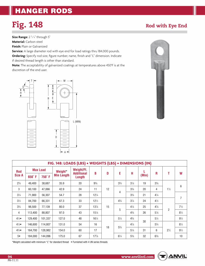
HANGER RODS
www.anvilintl.com94
Fig. 148 Rod with Eye End
Size Range: 2 3⁄4" through 5"Material: Carbon steelFinish: Plain or GalvanizedService: A large diameter rod with eye end for load ratings thru 184,000 pounds.Ordering: Specify rod size, figure number, name, finish and “L” dimension. Indicate if desired thread length is other than standard.Note: The acceptability of galvanized coatings at temperatures above 450°F is at the discretion of the end user.
FIG. 148: LOADS (LBS) • WEIGHTS (LBS) • DIMENSIONS (IN)
Rod Size A
Max Load Weight* Min Length
Weight/Ft. Additional
LengthB D E H L
(Min) R T W650˚ F 750˚ F
23⁄4 49,400 38,687 35.9 20 95⁄8
12
33⁄4 31⁄8 19 35⁄8
11⁄26
3 60,100 47,066 42.9 24 114
33⁄8 20 4
31⁄4 71,900 56,307 54.7 28 121⁄4 35⁄8 21 41⁄47
31⁄2 84,700 66,331 67.3 33 121⁄2
15
43⁄4 37⁄8 24 41⁄2
233⁄4 98,500 77,139 80.0 37 137⁄8
541⁄8 25 47⁄8 71⁄2
4 113,400 88,807 97.0 43 151⁄8 43⁄8 26 51⁄8 81⁄2
41⁄4 129,400 101,337 127.0 48 161⁄4
18
51⁄4 45⁄830
51⁄2 91⁄2
41⁄2 146,600 114,807 131.0 54 1653⁄4
47⁄8 53⁄4
21⁄2
81⁄2
43⁄4 164,700 128,982 154.0 60 17 51⁄8 31 6 91⁄2
184,000 144,096 175.0 67 177⁄8 61⁄4 53⁄8 32 63⁄8 10
B E
W
R
D
A
L (MIN)
H
T
5°
PH-11.11
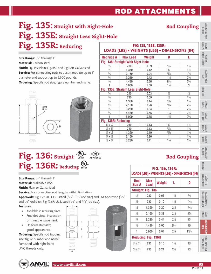
ROD ATTACHMENTS
www.anvilintl.com 95
Copp
er Tu
bing
Ha
nger
sPi
pe R
ings
Clev
is Ha
nger
sSt
eel P
ipe
Clam
psSo
cket
Clam
psSt
ructu
ral
Attac
hmen
tsBr
acke
tsCe
iling
Plat
es&
Flan
ges
Conc
rete
Inse
rts&
Attac
hmen
tsHa
nger
Rods
Rod
Atta
chm
ents
Bolts
, Nut
s,Pi
ns &
U-B
olts
Beam
Clam
psPi
ctoria
lTa
ble o
f Con
tents
CPVC
Pipe
Han
gers
Gene
ral
Notes
Fig. 135: Straight with Sight-Hole Rod Coupling
Fig. 135E: Straight Less Sight-Hole
Fig. 135R: Reducing
Size Range: 1⁄4" through 1"Material: Carbon steelFinish: Fig. 135: Plain; Fig.135E and Fig.135R GalvanizedService: For connecting rods to accommodate up to 1" diameter and support up to 5,900 pounds.Ordering: Specify rod size, figure number and name.
Fig. 136: Straight Rod Coupling
Fig. 136R: Reducing
Size Range: 1⁄4" through 1"Material: Malleable ironFinish: Plain or GalvanizedService: For connecting rod lengths within limitation.Approvals: Fig. 136: UL, ULC Listed ( 3⁄8" - 7⁄8" rod size) and FM Approved ( 3⁄8"and 1⁄2" rod size). Fig. 136R: UL Listed ( 1⁄2" and 3⁄8" rod size).Features:
• Available in reducing sizes.• Provides visual inspection of thread engagement.• Uniform strength; good appearance.
Ordering: Specify rod tapping size, figure number and name. Furnished with right-hand UNC threads only.
FIG 135, 135E, 135R:LOADS (LBS) • WEIGHTS (LBS) • DIMENSIONS (IN)
Rod Size A Max Load Weight D LFig. 135: Straight With Sight-Hole
3⁄8 730 0.09 9⁄16 11⁄81⁄2 1,350 0.12 3⁄4 11⁄25⁄8 2,160 0.24 15⁄16 17⁄83⁄4 3,230 0.42 11⁄8 21⁄47⁄8 4,480 0.66 15⁄16 25⁄81 5,900 1.00 11⁄2 3
Fig. 135E: Straight Less Sight-Hole1⁄4 240 0.03 3⁄8 7⁄83⁄8 730 0.09 5⁄8 11⁄81⁄2 1,350 0.14 11⁄16 13⁄45⁄8 2,160 0.26 13⁄16 21⁄83⁄4 3,230 0.34 1 21⁄47⁄8 4,480 0.55 11⁄4 21⁄21 5,900 0.75 13⁄8 23⁄4
Fig. 135R: Reducing3⁄8 x 1⁄4 240 0.13 5⁄8 11⁄21⁄2 x 3⁄8 730 0.13 11⁄16 11⁄45⁄8 x 1⁄2 1,350 0.19 13⁄16 11⁄43⁄4 x 5⁄8 2,160 0.26 1 11⁄27⁄8 x 3⁄4 3,230 0.41 11⁄4 13⁄4
FIG. 136, 136R:LOADS (LBS) • WEIGHTS (LBS) • DIMENSIONS (IN)
Rod Size A
Max Load Weight L D
Straight: Fig. 1361⁄4 230 0.06 13⁄8 5⁄8
3⁄8 730 0.10 15⁄8 11⁄16
1⁄2 1,350 0.20 21⁄8 15⁄16
5⁄8 2,160 0.33 21⁄2 11⁄8
3⁄4 3,230 0.44 25⁄8 11⁄4
7⁄8 4,480 0.96 33⁄16 15⁄8
1 5,900 0.94 23⁄4 113⁄16
Reducing: Fig. 136R3⁄8 x 1⁄4 230 0.10 15⁄8 15⁄8
1⁄2 x 3⁄8 730 0.21 21⁄8 21⁄8
L
SightHole
D
D
A
L
PH-11.11

ROD ATTACHMENTS
www.anvilintl.com96
Fig. 114 Turnbuckle Adjuster
Size Range: 1⁄4" through 3⁄4"Material: Malleable ironFinish: PlainInstallation: Normally used with split pipe ring, Fig. 108, see page 30.Approvals: Complies with Federal Specification A-A-1192A (Type 15), WW-H-171-E (Type 15), ANSI/MSS SP-69 and MSS SP-58 (Type 15).Maximum Temperature: 450° FFeatures:
• An economical and simple means of obtaining vertical adjustment and flexibility at the pipe connection.• Permits adjustment after pipe is in place.
Ordering: Specify rod size, figure number and name.
Fig. 110R Socket, Rod Threaded
Size Range: 1⁄4" through 7⁄8"Material: Malleable ironFinish: PlainService: For attaching hanger rod to various types of building attachmentsMaximum Temperature: 450° FApprovals: Complies with Federal Specification A-A-1192A (Type 16) WW-H-171-E (Type 16), ANSI/MSS SP-69 and MSS SP-58 (Type 16). UL Listed (Sizes 3⁄8" - 7⁄8") and FM Approved (Sizes 3⁄8" and 1⁄2").Installation: Normally used with the split pipe ring Fig. 108, see page 30.Ordering: Specify rod tapping size, figure number and name.
FIG. 114: LOADS (LBS) • WEIGHTS (LBS) • DIMENSIONS (IN)Rod Size A Max Load Weight B E H
1⁄4 230 0.09 21⁄2 11⁄4 7⁄32
3⁄8730
0.2837⁄8
17⁄813⁄32
1⁄2 0.31 113⁄16
5⁄8 0.7247⁄8 25⁄16
1⁄23⁄4 860 0.70 9⁄16
FIG. 110R: LOADS (LBS) • WEIGHTS (LBS) • DIMENSIONS (IN)Rod Size A Max Load Weight B E
1⁄4 650 0.051⁄4
11⁄83⁄8 800 0.07 111⁄32
1⁄2 1,000 0.13 117⁄32
5⁄8 1,400 0.19 3⁄8 113⁄16
3⁄4 2,200 0.311⁄2
25⁄32
7⁄8 2,300 0.44 211⁄32
A
EB
H
A
E
"B" MAX
PH-11.11

ROD ATTACHMENTS
www.anvilintl.com 97
Copp
er Tu
bing
Ha
nger
sPi
pe R
ings
Clev
is Ha
nger
sSt
eel P
ipe
Clam
psSo
cket
Clam
psSt
ructu
ral
Attac
hmen
tsBr
acke
tsCe
iling
Plat
es&
Flan
ges
Conc
rete
Inse
rts&
Attac
hmen
tsHa
nger
Rods
Rod
Atta
chm
ents
Bolts
, Nut
s,Pi
ns &
U-B
olts
Beam
Clam
psPi
ctoria
lTa
ble o
f Con
tents
CPVC
Pipe
Han
gers
Gene
ral
Notes
Fig. 157 Extension piece
Size Range: 3⁄8" through 7⁄8"Material: Malleable ironFinish: Plain or GalvanizedMaximum Temperature: 450° FService: For attaching hanger rod to various types of buildingattachments.Approvals: UL Listed (3⁄8" - 7⁄8" rod size) and FM Approved (3⁄8" &1⁄2" rod size).Installation: May be used to form an integral part of malleable ironbeam clamps Fig. 218, see page 64.Ordering: Specify rod size, figure number, name and finish.
FIG. 157: LOADS (LBS) • WEIGHTS (LBS) • DIMENSIONS (IN)Rod Size
AMaxLoad Weight B C Rod
Take-Out – E G H K3⁄8 730 0.20 11⁄4 21⁄16 11⁄4 1⁄2
1⁄2
9⁄16
1⁄2 1,350 0.40 13⁄8 25⁄16 13⁄85⁄8
11⁄16
5⁄8 1,550 0.44 11⁄2 27⁄16 17⁄16 3⁄43⁄4 2,100 0.65 13⁄4 27⁄8 111⁄16 7⁄87⁄8 2,350 0.78 17⁄8 2 13⁄4 3⁄4 9⁄16
A
G
C
B
E
K
H
Fig. 290: Right-Hand Thread Weldless Eye Nut
Fig. 290L: Left-Hand Thread
Size Range: 3⁄8" through 2 1⁄2"Material: Forged steelFinish: Plain or GalvanizedService: For use on high temperature piping installations.Approvals: Complies with Federal Specification A-A-1192A (Type 17), WW-H-171-E (Type 17), ANSI/MSS SP-69 and MSS SP-58 (Type 17).Features:
• Supports loads equal to the full limitation of the hanger rod.• Provides flexible connection when used with straight thread rod.
Ordering: Specify rod size, figure number, name and finish.If other than standard combinationof eye nut number and rod size,specify eye nut number and specialrod tapping size.Note: The acceptability ofgalvanized coatings at temperaturesabove 450°F is at the discretion ofthe end user. Larger eye nutsfeaturing smaller rod sizes arecommonly available.
FIG. 290, 290L: LOADS (LBS) • WEIGHTS (LBS) • DIMENSIONS (IN)
Rod Size A
Max LoadWeight B C D E F G H Eye Nut
Number650˚ F 750˚ F3⁄8 730 572 0.63
11⁄2 13⁄16 1⁄2 2 13⁄8 11⁄16 11⁄4 11⁄2 1,350 1,057 0.635⁄8 2,160 1,692 0.623⁄4 3,230 2,530 0.607⁄8 4,480 3,508 1.70
2 111⁄16 3⁄4 25⁄8 115⁄16 1 13⁄4 21 5,900 4,620 1.70
11⁄4 9,500 7,440 3.6021⁄2 113⁄16 1 33⁄8 23⁄8 11⁄4 23⁄4 3
11⁄2 13,800 10,807 3.5013⁄4 18,600 14,566 16.40
4 4 11⁄2 61⁄4 4 21⁄4 33⁄4 42 24,600 19,265 15.90
21⁄4 32,300 25,295 15.4021⁄2 39,800 31,169 14.90
E
G
D
F
A
C
B
H (max)
PH-11.11

ROD ATTACHMENTS
www.anvilintl.com98
Fig. 299 Forged Steel Clevis
Size Range: 3⁄8" through 4"Material: Forged steelFinish: Plain or GalvanizedService: For use on high temperature piping installations.Approvals: Complies with Federal Specification A-A-1192A (Type 14), WW-H-171-E (Type 14),ANSI/MSS SP-69 and MSS SP-58 (Type 14).Features:
• Available with pin and cotter pins, if required.Ordering: Specify rod size, figure number, name and finish. If pin and cotter pins are required,specify “with pin”. If other than standard combination of clevis number and rod size is required,specify clevis number, special rod tapping size, pin size, grip.Note: The acceptability of galvanized coatings at temperatures above 450°F is at the discretion of the end user.
FIG. 299: LOADS (LBS) • WEIGHTS (LBS) • DIMENSIONS (IN)
Rod Size A
Max Load Weight Rod Take Out – B D N Pin Dia.
P T W Grip Clevis No.650˚ F 750˚ F Without Pin With Pin
3⁄8 730 572 0.9 1.0311⁄16 17⁄16 5⁄8
1⁄25⁄16 11⁄16
1⁄221⁄2 1,350 1,057 0.7 0.9 5⁄8
5⁄8 2,160 1,692 0.7 0.9 3⁄4 5⁄83⁄4 3,230 2,530 2.5 3.0
4 21⁄2 17⁄8
5⁄16 15⁄16
3⁄421⁄2
7⁄8 4,480 3,508 2.5 3.4 1 7⁄81 5,900 4,620 4.0 5.1
5 3 15⁄1611⁄8
1⁄211⁄2
13
11⁄4 9,500 7,440 3.8 5.5 13⁄8 11⁄411⁄2 13,800 10,807 6.0 8.5
631⁄2 15⁄8 15⁄8 13⁄4
11⁄231⁄2
13⁄4 18,600 14,566 8.0 12.9 4 13⁄4 17⁄8 2 42 24,600 19,265 16.0 23.3 7 5 21⁄4 21⁄4 5⁄8 21⁄2
21⁄2
521⁄4 32,300 25,295 26.0 35.1
8 6 23⁄421⁄2
3⁄4 3 621⁄2 39,800 31,169 25.5 36.0 23⁄423⁄4 49,400 38,687 36.0 50.0
9 7 33
7⁄8 31⁄2 73 60,100 47,066 35.0 51.5 31⁄4
31⁄4 71,900 56,307 90.0 116.0
10 8 4
31⁄2
11⁄2 4 4 831⁄2 84,700 66,331 88.0 118.0 33⁄433⁄4 98,500 77,139 86.0 120.0 4
113,400 88,807 84.0 122.0 41⁄4
W
PD T
GRIPT
B
A
N
PH-11.11

ROD ATTACHMENTS
www.anvilintl.com 99
Copp
er Tu
bing
Ha
nger
sPi
pe R
ings
Clev
is Ha
nger
sSt
eel P
ipe
Clam
psSo
cket
Clam
psSt
ructu
ral
Attac
hmen
tsBr
acke
tsCe
iling
Plat
es&
Flan
ges
Conc
rete
Inse
rts&
Attac
hmen
tsHa
nger
Rods
Rod
Atta
chm
ents
Bolts
, Nut
s,Pi
ns &
U-B
olts
Beam
Clam
psPi
ctoria
lTa
ble o
f Con
tents
CPVC
Pipe
Han
gers
Gene
ral
Notes
A
F
F
SightHoles
B = Opening CL
1/2 BRod Take Out
& Rod Adj.
A
B"1⁄2 BROD
TAKE OUT
Fig. 230 Turnbuckle
Size Range: 3⁄8" through 2 1⁄2"Material: Forged steelFinish: Plain or GalvanizedService: Provides adjustment up to 6" for 12" Fig. 230 and 3" for 6" Fig. 230.Approvals: Complies with Federal Specification A-A-1192A (Type 13), WW-H-171-E (Type 13), ANSI/MSS SP-69 and MSS SP-58 (Type 13).Ordering: Specify rod size, figure number,name and finish.Note: The acceptability of galvanized coatings at temperatures above 450°F is at the discretion of the end user.
Fig. 233 Turnbuckle
Size Range: 1 1⁄4" through 5"Material: Carbon steelFinish: Plain or GalvanizedServices: Provides adjustments up to 12" with loads up thru184,000 pounds.Approvals: Complies with Federal Specification A-A-1192A (Type 13),WW-H-171-E (Type 13), ANSI/MSS SP-69 and MSS SP-58 (Type 13).Ordering: Specify rod size,figure number, name, finish and opening dimension.
FIG. 230: LOADS (LBS) • WEIGHTS (LBS) • DIMENSIONS (IN)
Rod Size A
Max Load Weight
650°F 750°F B= 6" Opening
B=12" Opening
3⁄8 730 572 0.42 –1⁄2 1,350 1,057 0.65 1.205⁄8 2,160 1,692 0.98 1.583⁄4 3,230 2,530 1.50 2.357⁄8 4,480 3,508 1.90 4.05
1 5,900 4,620 2.60 4.02
11⁄4 9,500 7,440 4.50 –
11⁄2 13,800 10,807 6.40 –
13⁄4 18,600 14,566 11.00 –
2 24,600 19,265 14.90 –
21⁄4 32,300 25,295 19.60 –
21⁄2 39,800 31,169 26.90 –
available upon request
FIG. 233: LOADS (LBS) • WEIGHTS (LBS) • DIMENSIONS (IN)
Rod Size* A
Max Load
Weight/OpeningF
B= 6" B=12" B=18" B=24"11⁄4 9,500 – 9.0 10.8 12.6 21⁄8
11⁄2 13,800 – 12.4 14.9 17.423⁄8
13⁄4 18,600 – 11.7 14.2 16.7
2 24,600 – 20.9 24.7 28.5 33⁄16
21⁄4 32,300 – 29.5 34.6 39.731⁄4
21⁄2 39,800 – 28.3 33.4 38.5
23⁄4 49,400 35.6 41.8 48.1 54.3 31⁄2
3 60,100 41.6 49.1 56.6 64.1313⁄16
31⁄4 71,900 39.6 47.0 54.5 62.0
31⁄2 84,700 72.5 82.9 93.3 103.747⁄16
33⁄4 98,500 69.6 80.0 90.4 107.30
113,400 110.7 125.1 139.4 153.65
41⁄4 129,400 107.1 121.5 135.7 150.0
41⁄2 146,600 233.5 255.2 276.9 298.6
613⁄1643⁄4 164,700 227.6 249.3 271.0 292.7
184,000 221.4 243.1 264.8 286.5
PH-11.11

BOLTS, NUTS, PINS & U-BOLTS
www.anvilintl.com100
Fig. 291 Clevis Pin with Cotters
Size Range: 1⁄2" through 4"Material: Carbon steelFinish: Plain or GalvanizedMaximum Temperature: 650° FService: For use with type C variable spring hanger, type C constant support (Fig. 81-H only) and Fig. 66 welded beam attachment.Ordering: Specify pin diameter, figure number, name, finish and if cotter pins are required.Note: The acceptability of galvanized coatings at temperatures above 450°F is at the discretion of the end user.
FIG. 291: LOADS (LBS) • WEIGHTS (LBS) • DIMENSIONS (IN)
Pin Dia. D
Max LoadWeight L W E H Cotter Pin
Size650˚ F 750˚ F1⁄2 730 572 0.12 27⁄8 21⁄8
3⁄8
5⁄32 1⁄8 x 11⁄45⁄8 1,350 1,057 0.18 31⁄8 23⁄83⁄4 2,160 1,691 0.29 35⁄8 27⁄8
7⁄32
3⁄16 x 11⁄27⁄8 3,230 2,529 0.47 41⁄4 31⁄2
1 4,480 3,508 0.67 4 31⁄43⁄16 x 2
11⁄8 5,900 4,620 1.00 43⁄4 4
13⁄8 9,500 7,439 2.10 53⁄8 43⁄81⁄2 9⁄32
1⁄4 x 21⁄2
15⁄8 13,800 10,805 3.30 6 5 1⁄4 x 3
17⁄8 18,600 14,564 4.8071⁄8 57⁄8
5⁄8 3⁄8
3⁄8 x 3
21⁄4 24,600 19,262 7.20 3⁄8 x 31⁄4
21⁄2 32,300 25,291 9.30 75⁄8 63⁄8 3⁄8 x 33⁄4
23⁄4 39,800 31,163 12.50 77⁄8 65⁄8 3⁄8 x 4
3 49,400 38,680 16.60 81⁄4 63⁄4
3⁄4 1⁄2
1⁄2 x 531⁄4 60,100 47,058 20.00 81⁄2 7
31⁄2 71,900 56,298 23.90 83⁄4 71⁄41⁄2 x 633⁄4 84,700 66,320 25.10 91⁄2 8
4 98,500 77,125 34.80 93⁄4 81⁄4
L
D
W
E
H
PH-11.11

BOLTS, NUTS, PINS & U-BOLTS
www.anvilintl.com 101
Copp
er Tu
bing
Ha
nger
sPi
pe R
ings
Clev
is Ha
nger
sSt
eel P
ipe
Clam
psSo
cket
Clam
psSt
ructu
ral
Attac
hmen
tsBr
acke
tsCe
iling
Plat
es&
Flan
ges
Conc
rete
Inse
rts&
Attac
hmen
tsHa
nger
Rods
Rod
Attac
hmen
tsBo
lts, N
uts,
Pins
& U
-Bol
tsBe
amCl
amps
Picto
rial
Tabl
e of C
onten
tsCP
VCPi
pe H
ange
rsGe
nera
lNo
tes
Machine Bolts
Size Range: American Standard hexagon head bolts with American Standard hexagon nuts are stocked in sizes 3⁄8" through 1 1⁄8" UNC thread series. Other sizes are available upon request. Lengths of bolts are measured from under head to extreme point.Finish: Plain or ElectroplatedOrdering: Specify bolt size, name and length.
Hexagon Nuts
Size Range:• American Standard hexagon nuts -
sizes 1⁄4" thru 1 1⁄2".• American Standard heavy hexagon flat nuts - sizes 1 3⁄4" thru 3 3⁄4".Finish: Plain or ElectroplatedOrdering: Specify bolt or rod size and name.
HEX NUTS: DIMENSIONS (IN)
Bolt /Rod Size Width Thickness
1⁄4 7⁄16 15⁄64
3⁄8 9⁄16 11⁄32
1⁄2 3⁄4 29⁄64
5⁄8 15⁄16 9⁄16
3⁄4 11⁄8 43⁄64
7⁄8 15⁄16 25⁄32
1 11⁄2 57⁄64
11⁄4 17⁄8 13⁄32
13⁄8 21⁄16 113⁄64
11⁄2 21⁄4 15⁄16
HEAVY HEX NUTS: DIMENSIONS (IN)
Bolt /Rod Size Width Thickness
13⁄4 23⁄4 125⁄32
2 31⁄8 21⁄32
21⁄4 31⁄2 219⁄64
21⁄2 37⁄8 235⁄64
23⁄4 41⁄4 213⁄16
3 45⁄8 31⁄16
31⁄4 ■ 5 35⁄16
31⁄2 ■ 53⁄8 39⁄16
33⁄4 ■ 53⁄4 313⁄16
■ Furnished with 8 UN or 4 UN threads as required.
PH-11.11
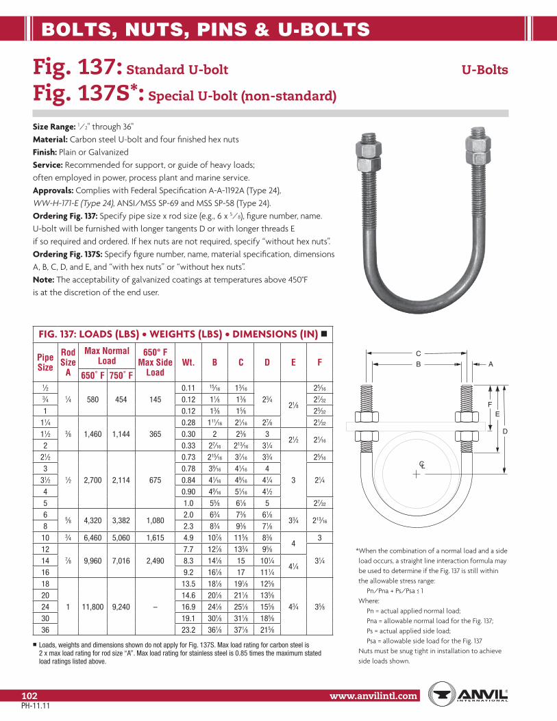
BOLTS, NUTS, PINS & U-BOLTS
www.anvilintl.com102
Fig. 137: Standard U-bolt U-Bolts
Fig. 137S*: Special U-bolt (non-standard)
Size Range: 1⁄2" through 36"Material: Carbon steel U-bolt and four finished hex nutsFinish: Plain or GalvanizedService: Recommended for support, or guide of heavy loads; often employed in power, process plant and marine service.Approvals: Complies with Federal Specification A-A-1192A (Type 24), WW-H-171-E (Type 24), ANSI/MSS SP-69 and MSS SP-58 (Type 24).Ordering Fig. 137: Specify pipe size x rod size (e.g., 6 x 5⁄8), figure number, name. U-bolt will be furnished with longer tangents D or with longer threads E if so required and ordered. If hex nuts are not required, specify “without hex nuts”.Ordering Fig. 137S: Specify figure number, name, material specification, dimensions A, B, C, D, and E, and “with hex nuts” or “without hex nuts”.Note: The acceptability of galvanized coatings at temperatures above 450°F is at the discretion of the end user.
FIG. 137: LOADS (LBS) • WEIGHTS (LBS) • DIMENSIONS (IN) ■
Pipe Size
Rod Size
A
Max Normal Load
650° F Max Side
LoadWt. B C D E F
650˚ F 750˚ F1⁄2
1⁄4 580 454 1450.11 15⁄16 13⁄16
23⁄421⁄8
25⁄16
3⁄4 0.12 11⁄8 13⁄8 27⁄32
1 0.12 13⁄8 15⁄8 23⁄32
11⁄43⁄8 1,460 1,144 365
0.28 111⁄16 21⁄16 27⁄8 21⁄32
11⁄2 0.30 2 23⁄8 321⁄2 21⁄16
2 0.33 27⁄16 213⁄16 31⁄421⁄2
1⁄2 2,700 2,114 675
0.73 215⁄16 37⁄16 33⁄4
3
25⁄16
3 0.78 39⁄16 41⁄16 421⁄431⁄2 0.84 41⁄16 49⁄16 41⁄4
4 0.90 49⁄16 51⁄16 41⁄25 1.0 55⁄8 61⁄8 5 27⁄32
65⁄8 4,320 3,382 1,080
2.0 63⁄4 73⁄8 61⁄833⁄4 213⁄16
8 2.3 83⁄4 93⁄8 71⁄810 3⁄4 6,460 5,060 1,615 4.9 107⁄8 115⁄8 83⁄8
43
127⁄8 9,960 7,016 2,490
7.7 127⁄8 133⁄4 95⁄831⁄414 8.3 141⁄8 15 101⁄4
41⁄416 9.2 161⁄8 17 111⁄418
1 11,800 9,240 –
13.5 181⁄8 191⁄8 125⁄8
43⁄4 35⁄820 14.6 201⁄8 211⁄8 135⁄824 16.9 241⁄8 251⁄8 155⁄830 19.1 301⁄8 311⁄8 185⁄836 23.2 361⁄8 371⁄8 215⁄8
■ Loads, weights and dimensions shown do not apply for Fig. 137S. Max load rating for carbon steel is 2 x max load rating for rod size “A”. Max load rating for stainless steel is 0.85 times the maximum stated load ratings listed above.
*When the combination of a normal load and a side load occurs, a straight line interaction formula may be used to determine if the Fig. 137 is still within the allowable stress range:
Pn/Pna + Ps/Psa ≤ 1Where:
Pn = actual applied normal load; Pna = allowable normal load for the Fig. 137;Ps = actual applied side load; Psa = allowable side load for the Fig. 137
Nuts must be snug tight in installation to achieve side loads shown.
A
E
D
C
B
F
CL
PH-11.11
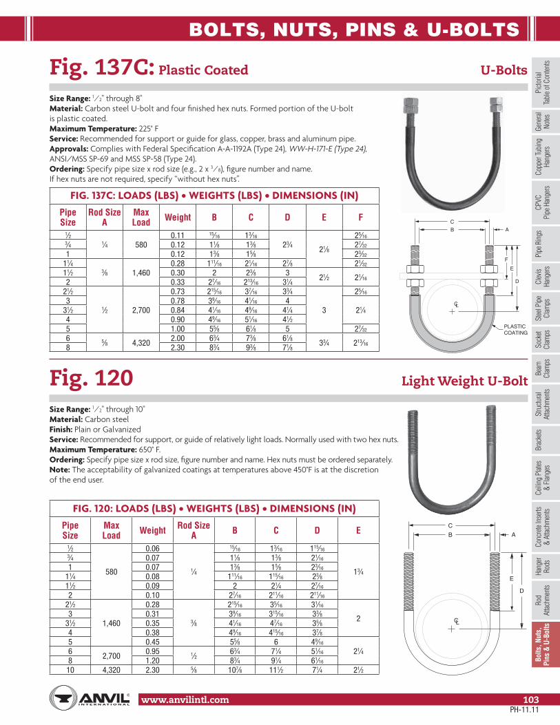
BOLTS, NUTS, PINS & U-BOLTS
www.anvilintl.com 103
Copp
er Tu
bing
Ha
nger
sPi
pe R
ings
Clev
is Ha
nger
sSt
eel P
ipe
Clam
psSo
cket
Clam
psSt
ructu
ral
Attac
hmen
tsBr
acke
tsCe
iling
Plat
es&
Flan
ges
Conc
rete
Inse
rts&
Attac
hmen
tsHa
nger
Rods
Rod
Attac
hmen
tsBo
lts, N
uts,
Pins
& U
-Bol
tsBe
amCl
amps
Picto
rial
Tabl
e of C
onten
tsCP
VCPi
pe H
ange
rsGe
nera
lNo
tes
Fig. 137C: Plastic Coated U-Bolts
Size Range: 1⁄2" through 8"Material: Carbon steel U-bolt and four finished hex nuts. Formed portion of the U-boltis plastic coated.Maximum Temperature: 225° FService: Recommended for support or guide for glass, copper, brass and aluminum pipe.Approvals: Complies with Federal Specification A-A-1192A (Type 24), WW-H-171-E (Type 24),ANSI/MSS SP-69 and MSS SP-58 (Type 24).Ordering: Specify pipe size x rod size (e.g., 2 x 3⁄8), figure number and name. If hex nuts are not required, specify “without hex nuts”.
Fig. 120 Light Weight U-Bolt
Size Range: 1⁄2" through 10"Material: Carbon steelFinish: Plain or GalvanizedService: Recommended for support, or guide of relatively light loads. Normally used with two hex nuts.Maximum Temperature: 650° F.Ordering: Specify pipe size x rod size, figure number and name. Hex nuts must be ordered separately.Note: The acceptability of galvanized coatings at temperatures above 450°F is at the discretionof the end user.
FIG. 137C: LOADS (LBS) • WEIGHTS (LBS) • DIMENSIONS (IN)
Pipe Size
Rod Size A
Max Load Weight B C D E F
1⁄21⁄4 580
0.11 15⁄16 13⁄16
23⁄4 21⁄8
25⁄163⁄4 0.12 11⁄8 13⁄8 27⁄32
1 0.12 13⁄8 15⁄8 23⁄32
11⁄43⁄8 1,460
0.28 111⁄16 21⁄16 27⁄8 21⁄32
11⁄2 0.30 2 23⁄8 3 21⁄2 21⁄162 0.33 27⁄16 213⁄16 31⁄421⁄2
1⁄2 2,700
0.73 215⁄16 37⁄16 33⁄4
3
25⁄16
3 0.78 39⁄16 41⁄16 421⁄431⁄2 0.84 41⁄16 49⁄16 41⁄4
4 0.90 49⁄16 51⁄16 41⁄25 1.00 55⁄8 61⁄8 5 27⁄32
6 5⁄8 4,320 2.00 63⁄4 73⁄8 61⁄8 33⁄4 213⁄168 2.30 83⁄4 93⁄8 71⁄8
FIG. 120: LOADS (LBS) • WEIGHTS (LBS) • DIMENSIONS (IN)
Pipe Size
Max Load Weight Rod Size
A B C D E
1⁄2
580
0.06
1⁄4
15⁄16 13⁄16 115⁄16
13⁄4
3⁄4 0.07 11⁄8 13⁄8 21⁄16
1 0.07 13⁄8 15⁄8 23⁄16
11⁄4 0.08 111⁄16 115⁄16 23⁄811⁄2 0.09 2 21⁄4 27⁄16
2 0.10 27⁄16 211⁄16 211⁄16
21⁄2
1,460
0.28
3⁄8
215⁄16 35⁄16 31⁄16
23 0.31 39⁄16 315⁄16 33⁄831⁄2 0.35 41⁄16 47⁄16 35⁄84 0.38 49⁄16 415⁄16 37⁄85 0.45 55⁄8 6 49⁄16
21⁄46 2,700 0.95 1⁄2 63⁄4 71⁄4 51⁄16
8 1.20 83⁄4 91⁄4 61⁄16
10 4,320 2.30 5⁄8 107⁄8 111⁄2 71⁄4 21⁄2
PLASTICCOATING
A
E
D
C
B
F
CL
A
E
D
C
B
CL
PH-11.11

STRAPS
www.anvilintl.com104
Fig. 262 Strap Short
Size Range: 1⁄2" through 4"Material: Carbon steelFinish: Plain or GalvanizedMaximum Temperature: 650° FApprovals: Complies with Federal Specification A-A-1192A (Type 26), WW-H-171-E (Type 26),ANSI/MSS SP-69 and MSS SP-58 (Type 26).Ordering: Specify pipe size, figure number, name and finish.Note: The acceptability of galvanized coatings at temperatures above 450°F is at the discretion of the end user.
Fig. 126 One-Hole Clamp
Size Range: 3⁄8" through 4"Material: Malleable ironFinish: Plain or GalvanizedService: For support of standard conduit, cable and steel pipe on walls or sides of beams. Not recommended for use horizontally on ceilings, bottoms of beams and similar installations since the factor of safety is greatly reduced when so used.Maximum Temperature: 450° FOrdering: Specify pipe size, figure number, name and finish. Specify nominal size of conduitor pipe or outside diameter of leadcable with which the clamp is to be used.
FIG. 262: LOADS (LBS) • WEIGHTS (LBS) • DIMENSIONS (IN)
Pipe Size
Max LoadWeight Screw or
Bolt Size ■ L B C D E Fw/Lag Screws
w/Bolts to Steel
1⁄2
300 410
0.20Two #18 x 2 steel wood screws or
two 3⁄8" bolts to steel
4
11⁄4
23⁄4 1⁄2 11⁄8
1⁄8
3⁄4 0.23 43⁄8 31⁄8 11⁄16 17⁄16
1 0.26 43⁄4 31⁄2 11⁄16 15⁄811⁄4 0.36 5 33⁄4 11⁄16 21⁄811⁄2 0.54 53⁄8 41⁄8 13⁄8 21⁄22 0.60 63⁄8 51⁄8 11⁄4 23⁄4
21⁄2
450 610
1.40 Two #18 x 3 steel wood screws or
two 3⁄8" bolts to steel
613⁄16
11⁄2
59⁄16 13⁄4 35⁄8
1⁄43 1.60 75⁄16 61⁄16 17⁄8 4
31⁄2 1.80 713⁄16 69⁄16 23⁄16 45⁄84 1.90 83⁄8 71⁄8 23⁄8 5
■ Screws or bolts not included
FIG. 126: WEIGHTS (LBS) • DIMENSIONS (IN)
Pipe Size
Cable Size or Outside Dia. of Conduit ■ Weight Dia. of
Hole - ASize Screw/
Bolt3⁄8 0.67 0.03 1⁄4 No. 101⁄2 0.84 0.03
5⁄16 1⁄43⁄4 1.05 0.051 1.31 0.09
11⁄4 1.66 0.12 3⁄811⁄2 1.90 0.16 7⁄16 3⁄82 2.37 0.25
21⁄2 2.87 0.49 11⁄16 5⁄83 3.50 0.824 4.50 1.30 3⁄4
■ Screws or bolts not included
E
CL
D
F
B
CL
A
CL
PH-11.11

STRAPS
Stra
psSp
ring
Hang
ers
Cons
tant
Supp
orts
Vibr
ation
Con
trol
& Sw
ay B
race
Sway
Stru
tAs
sem
bly
Snub
bers
Appl
icatio
nEx
ampl
esTe
chni
cal
Data
Spec
ial D
esig
nPr
oduc
tsTr
apez
ePi
pe R
oll
Pipe
Gui
des
& Sl
ides
Pipe
Shi
elds
& Sa
ddles
Pipe
Supp
orts
Mas
ter F
orm
at3
Part
Spec
s.In
dex
www.anvilintl.com 105
Fig. 243 Pipe Strap
Size Range: 1⁄2" through 6" pipeMaterial: Carbon steelFinish: PlainService: Restraint of pipe in specified direction while permitting movement in non-restrained direction.Maximum Temperature: 650° FOrdering: Specify figure number, name, and pipe size. Larger sizes available upon request.
Fig. 244 Pipe Strap
Size Range: 1⁄2" through 6" pipeMaterial: Carbon steelFinish: PlainService: Restraint of pipe in specified direction while permitting movement in non-restrained direction.Maximum Temperature: 650° FOrdering: Specify figure number, name, and pipe size. Larger sizes available upon request.
FIG. 243: LOADS (LBS) • WEIGHT (LBS) • DIMENSIONS (IN)
Pipe Size L T W Rated
Load Pn Weight
1⁄2 31⁄4 2 600
0.713⁄4 31⁄2 0.841 4 0.98
11⁄4 41⁄23⁄8
31,500
2.6411⁄2 5 2.942 51⁄2 3.39
21⁄2 6
1⁄2
2,500 5.203 61⁄2
4 2,8007.93
4 71⁄2 9.636 93⁄4 6 3,000 19.97
FIG. 244: LOADS (LBS) • WEIGHT (LBS) • DIMENSIONS (IN)
Pipe Size
Rated LoadL T W Weight
Ps Pn1⁄2
250 1,5001
1⁄4 20.39
3⁄4 13⁄16 0.471 17⁄16 0.56
11⁄4500 2,000
13⁄43⁄8
3
1.6211⁄2 2 1.812 21⁄2 2.20
21⁄2650
2,300
3
1⁄2
3.563 37⁄8
45.74
4 43⁄4 7.166 700 63⁄4 6 15.32
1⁄16Pn
L T
FIELDWELD
W
CL
FIELDWELD
1⁄16Pn
Ps
L T W
CL
PH-11.11

PIPE SUPPORTS
www.anvilintl.com106
Fig. 62, Type A, B and C Pipe Stanchion
Size Range: 2" through 18"Material: Carbon steelFinish: Plain or GalvanizedService: Stanchion type of support for stationary pipe where vertical adjustment is required.Maximum Temperature: Plain 650° F, Galvanized 450˚ FOrdering: Specify figure number, type, pipe size, top stanchion size, material specification and “D” dimension. For base plates that require holes, also specify hole size, and the center line to center line of the holes.
DIMENSIONS (IN)
Top Stanchion
Bottom Stanchion
Base Plate
11⁄2 2 Std. 3⁄8 x 6 x 621⁄2 3 Std. 3⁄8 x 10 x 104 5 Sch. 80 3⁄8 x 10 x 105 6 Sch. 80 3⁄8 x 10 x 10
Pipe or Elbow Size (in)
Top Stanchion Size (Standard Weight Pipe)
11⁄2 21⁄2 4 52
21⁄2
3
4
5
6
8
10
12
14
16
18
Weight (Lbs) 12 28 55 75
TopStanchion
3" Min
BottomStanchion
D ±1" Adj.
1⁄4" VentHole
FieldWeld
Base Plate
FieldWeld
TopStanchion
BottomStanchion
Base Plate
D ±1" Adj.
1⁄4" VentHole
3" Min
1⁄4" VentHole
FieldWeld
CL
TopStanchion
BottomStanchion
Base Plate
D ±1" Adj. 3" Min
Fig. 62, Type A(L. R. Elbow) with adjustable base
Fig. 62, Type B(S. R. Elbow) with adjustable base
Fig. 62, Type C(Horizontal Pipe) with adjustable base
Fig. 62Stanchion with Adjustable Base
PH-11.11

PIPE SUPPORTS
Stra
psSp
ring
Hang
ers
Cons
tant
Supp
orts
Vibr
ation
Con
trol
& Sw
ay B
race
Sway
Stru
tAs
sem
bly
Snub
bers
Appl
icatio
nEx
ampl
esSp
ecial
Des
ign
Prod
ucts
Trap
eze
Pipe
Rol
lPi
pe G
uide
s&
Slid
esPi
pe S
hield
s&
Sadd
lesPi
peSu
ppor
tsIn
dex
www.anvilintl.com 107
Tech
nica
lDa
taM
aster
For
mat
3 Pa
rt Sp
ecs.
Pipe or Elbow Size (in)
Stanchion Size (Standard Weight Pipe)
11⁄2 2 21⁄2 3 4 5 6 8 10 12 14 16 20 24
21⁄234568101214161820222426283032343642
Weight (Lbs) 9.5 11.6 16.4 23.7 31.8 47.0 59.0 100.0 164.0 201.0 230.0 282.0 374.0 515.0
See Figure 258, 259, 264, or 265 dimensional data for required stanchion pipe size (nominal pipe size A).
DIMENSIONS (IN)
Stanchion Size Base Plate
11⁄23⁄8 x 6 x 6
2
21⁄2
3⁄8 x 8 x 83
4
53⁄8 x 10 x 10
6
8 3⁄8 x 14 x 14
101⁄2 x 18 x 18
12
14 1⁄2 x 20 x 20
16 1⁄2 x 22 x 22
20 1⁄2 x 24 x 24
24 1⁄2 x 30 x 30
Fig. 63Stanchion
Fig. 63, Type C(Horizontal Pipe)
Fig. 63, Type B(S. R. Elbow)
Fig. 63, Type A(L. R. Elbow)
1⁄4" VentHoleD
Stanchion
Base Plate
Stanchion
Base Plate
D1⁄4" VentHole
Stanchion
Base Plate
D
CL
1⁄4" VentHole
H
CL
Stanchion
Base Plate
Stanchion
H
CL
Base Plate
Fig. 63, Type PSquare Cut End for usewith Figure 258 or 259Pipe Saddle Support(See pages 109 & 112)
Fig. 63, Type TSquare Cut Threaded End
for use with Figure 264 or 265Adjustable Pipe Saddle Support
(See pages 110 & 111)
Fig. 63, Type A, B, C, P and T Pipe Stanchion
Material: Carbon steelFinish: Plain or GalvanizedMaximum Temperature: Plain 650° F, Galvanized 450˚ FTo Order Specify: Type A, B, C: Figure Number, Type, Pipe Size, Stanchion Size, Material Specification and “D” Dimension. Type P: Figure Number, Type, Saddle Size, Stanchion Size, Material Specification and “H” Dimension. Type T: Figure Number, Type, Saddle Figure Number and Size, Stanchion Size, Material Specification and “H” Dimension.For base plates that require holes, also specify hole size, and the center line to center line of the holes.
PH-11.11

PIPE SUPPORTS
www.anvilintl.com108
A
C
8"
E
G
CL
Fig. 192 Adjustable Pipe Saddle
Size Range: 2" through 12"Material: Carbon steelFinish: Plain or GalvanizedService: Stanchion type support for stationary pipe where vertical adjustment is required.Approvals: Complies with Federal Specification A-A-1192A(Type 38), ANSI/MSS SP-69 and MSS SP-58 (Type 38).Ordering: Specify pipe size to be supported, figure number,name and finish.
Fig. 191 Adjustable Pipe Saddle with U-Bolt
Size Range: 2" through 12"Material: Carbon steelFinish: Plain or GalvanizedService: Stanchion type support where vertical adjustmentis required, plus the additional stability provided by U-boltattachment to stationary pipe.Approvals: Complies with Federal Specification A-A-1192A(Type 37), ANSI/MSS SP-69 and MSS SP-58 (Type 37).Ordering: Specify pipe size, figure number, name and finish.
FIG. 192: WEIGHTS (LBS) • DIMENSIONS (IN)
Pipe Size
Rod Size A E G Weight
2
5⁄8
97⁄16
1⁄4 x 1
1.021⁄2 911⁄16 1.43 10 1.6
31⁄2 101⁄4 2.64
7⁄8101⁄2
1⁄4 x 11⁄43.0
5 11 3.26
11111⁄16
3⁄8 x 11⁄24.9
8 1211⁄16 6.210
11⁄4137⁄8
1⁄2 x 210.5
12 147⁄8 11.8
FIG. 191: WEIGHTS (LBS) • DIMENSIONS (IN)
Pipe Size
Rod SizeA C E G Weight
25⁄8
211⁄16 97⁄16
1⁄4 x 1
1.221⁄2 35⁄16 911⁄16 1.43 315⁄16 10 1.6
31⁄2 47⁄16 101⁄4 2.64 7⁄8
51⁄4 101⁄2 1⁄4 x 11⁄43.0
5 61⁄8 11 3.26
171⁄4 1111⁄16 3⁄8 x 11⁄2
4.98 93⁄8 1211⁄16 6.2
1011⁄4
111⁄2 137⁄8 1⁄2 x 210.5
12 131⁄2 147⁄8 11.8
8"
G
A
E
120°
CL
PH-11.11

PIPE SUPPORTS
Stra
psSp
ring
Hang
ers
Cons
tant
Supp
orts
Vibr
ation
Con
trol
& Sw
ay B
race
Sway
Stru
tAs
sem
bly
Snub
bers
Appl
icatio
nEx
ampl
esSp
ecial
Des
ign
Prod
ucts
Trap
eze
Pipe
Rol
lPi
pe G
uide
s&
Slid
esPi
pe S
hield
s&
Sadd
lesPi
peSu
ppor
tsIn
dex
www.anvilintl.com 109
Tech
nica
lDa
taM
aster
For
mat
3 Pa
rt Sp
ecs.
Fig. 258 Pipe Saddle Support
Size Range: 4" through 36"Material: Sizes 4" through 12" are Cast Iron. Sizes 14" through 36" are Carbon Steel.Sizes 4" through 12" are available in Carbon Steel by special request only.Finish: Plain or GalvanizedService: Stanchion type support for stationary pipe.Approvals: Complies with Federal Specification A-A-1192A (Type 36), WW-H-171-E (Type 36 & 37), ANSI/MSS SP-69 and MSS SP-58 (Type 36).Installation: Slip saddle base into riser pipe.Ordering: Specify size to be supported, figure number, name, finish and material.Order Separately: Figure 63P Square Cut End Stanchion. Specify "H" and pipesize to be supported by Figure 258.
FIG. 258: WEIGHTS (LBS) • DIMENSIONS (IN)
Pipe Size Weight A B Width C Max Load
4 9.1
3
43⁄16
35⁄8 3,800
5 10.8 413⁄16
6 11.8 57⁄16
8 14.3 615⁄16
10 19.3 87⁄16
12 23.1 915⁄16
14 15.0 101⁄24 5,300
16 16.0 111⁄218 23.0
4
131⁄2
5
6,70020 24.0 141⁄222 26.0 151⁄2
7,300
24 30.0 171⁄226 32.0 181⁄230 41.0 205⁄832 42.0 215⁄836 46.0 235⁄8 83⁄4
*Standard Wall Pipe The above load ratings are applicable to the saddle only and are not applicable to the stanchion or other means used to support the saddle.
Fig. 258 Cast
Fig. 258 Fabricated Steel
ANOM. PIPE
SIZE
C
B
3"
CL
H
CL
Stanchion
Base Plate
Fig. 63, Type PSquare Cut End for use with Figure
258 or 259 Pipe Saddle Support
PH-11.11

PIPE SUPPORTS
www.anvilintl.com110
NOM. PIPESIZE - D
NOM. PIPESIZE - A
C
B
E
CL
3"
FIG. 264: LOADS (LBS) • WEIGHT (LBS) • DIMENSIONS (IN)Pipe Size
WeightA B D
E Width C
Max LoadComplete Saddle Only Min Max
21⁄2 9.0 4.821⁄2
31⁄211⁄2
8 133 1,8003 9.2 5.0 33⁄4 81⁄4 131⁄4
31⁄2 9.4 5.2 4 81⁄2 131⁄24 15.0 7.6
3
41⁄4
21⁄2
91⁄4 14
35⁄8 3,800
5 16.7 8.3 47⁄8 10 143⁄46 17.7 10.3 51⁄2 101⁄2 151⁄48 20.2 12.8 67⁄8 113⁄4 161⁄210 25.2 17.8 81⁄2 131⁄2 181⁄412 29.0 21.6 915⁄16 15 193⁄414 40.2 38.0 4 1015⁄16 3 161⁄4 203⁄4
45⁄8 5,30016 53.2 42.0 123⁄8 173⁄4 221⁄418 70.8 51.0
6
137⁄8 31⁄2 191⁄2 24 6,70020 104.8 85.0 153⁄8 21 251⁄2
63⁄422 121.0 98.0 151⁄2
4
215⁄16 2513⁄16
7,300
24 137.0 110.0 1715⁄16 233⁄4 281⁄426 154.0 130.0 181⁄2 245⁄16 2813⁄16
30 170.0 150.0 215⁄16 27 311⁄232 181.0 161.1 221⁄2 281⁄4 323⁄4 83⁄436 249.0 229.0 241⁄2 301⁄4 343⁄4
* The special cast iron reducer may be furnished with a hexed shaped smaller end.* Standard Wall PipeThe above load ratings are applicable to the saddle only and are not applicable to the stanchion or other means used to support the saddle.
Fig. 264 Adjustable Pipe Saddle Support
Size Range: 2 1⁄2" through 36"Material: Cast iron saddle, locknut nipple and special cast iron reducer, assembled.Finish: Plain or GalvanizedService: Stanchion type support where vertical adjustment of stationary pipe is required.Approvals: Complies with Federal Specification A-A-1192A (Type 38), WW-H-171-E (Type 39),ANSI/MSS SP-69 and MSS SP-58 (Type 38).Installation: Adjustment is obtained by turning the locknut nipple. The lower end of the nipple is staked, upsetting the threads to prevent separation of nipple and coupling during adjustment.Features:
• Vertical adjustment of approximately 4 1⁄2"• Saddle supports a broad range of pipe sizes
Ordering: Specify pipe size to be supported, figure number, name and finish.Order Separately: Figure 63T Square Cut Threaded End Stanchion. Specify "H" and pipe size to besupported by Figure 264.
Stanchion
H
CL
Base Plate
Fig. 63, Type TSquare Cut Threaded End for use with Figure 264 or 265 Adjustable Pipe Saddle Support
PH-11.11

PIPE SUPPORTS
Stra
psSp
ring
Hang
ers
Cons
tant
Supp
orts
Vibr
ation
Con
trol
& Sw
ay B
race
Sway
Stru
tAs
sem
bly
Snub
bers
Appl
icatio
nEx
ampl
esSp
ecial
Des
ign
Prod
ucts
Trap
eze
Pipe
Rol
lPi
pe G
uide
s&
Slid
esPi
pe S
hield
s&
Sadd
lesPi
peSu
ppor
tsIn
dex
www.anvilintl.com 111
Tech
nica
lDa
taM
aster
For
mat
3 Pa
rt Sp
ecs.
C
B
CL
NOM. PIPESIZE - D
NOM. PIPESIZE - A
E 3"
FIG. 265: LOADS (LBS) • WEIGHT (LBS) • DIMENSIONS (IN)Pipe Size
WeightA B D
E Width C
Max LoadComplete Saddle Only Min Max
4 22.0 10.8
4
43⁄16
3
91⁄2 14
35⁄8 3,800
5 23.1 12.1 413⁄16 101⁄8 145⁄86 23.9 12.7 57⁄16 103⁄4 151⁄48 32.5 21.3 615⁄16 121⁄4 163⁄4
10 36.9 25.7 87⁄16 133⁄4 181⁄412 42.4 31.2 915⁄16 145⁄8 191⁄814 39.2 28.0 101⁄2 1513⁄16 205⁄16
6
5,30016 42.2 31.0 111⁄2 1613⁄16 215⁄16
18 60.0 40.0
6
131⁄2 31⁄2 191⁄8 235⁄8 6,70020 63.0 43.0 141⁄2 201⁄8 245⁄822 66.0 46.0 151⁄2
4
215⁄16 2513⁄16
7,300
24 72.0 52.0 171⁄2 235⁄16 2713⁄16
26 75.0 57.0 181⁄2 245⁄16 2813⁄16
30 89.0 69.0 205⁄8 267⁄16 3015⁄16
32 93.0 73.0 215⁄8 277⁄16 3115⁄16
36 101.0 81.0 235⁄8 297⁄16 3315⁄16
* The special cast iron reducer may be furnished with a hexed shaped smaller end.* Standard Wall PipeThe above load ratings are applicable to the saddle only and are not applicable to the stanchion or other means used to support the saddle.
Fig. 265 Adjustable Pipe Saddle Support with U-Bolt
Size Range: 4" through 36"Material: Cast iron saddle, steel yoke and nuts, steel locknut nipple and special cast iron reducer. (14" through 36" carbon steel saddle with steel yoke. 4" through 12" steel saddle available upon special request)Finish: Plain or GalvanizedService: Stanchion type support where vertical adjustment is required, plus the additional stability provided by U-bolt attachment to pipe.Approvals: Complies with Federal Specification A-A-1192A (Type 38), WW-H-171-E (Type 39),ANSI/MSS SP-69 and MSS SP-58 (Type 38).Installation: Adjustment is obtained by turning the locknut nipple. The lower end of the nippleis staked, upsetting the threads to prevent separation of nipple and coupling during adjustment.Features:
• Vertical adjustment of approximately 4 1⁄2"• Saddle supports a broad range of pipe sizes
Ordering: Specify pipe size to be supported, figure number, name and finish.Order Separately: Figure 63T Square Cut Threaded End Stanchion. Specify "H" and pipe size to besupported by Figure 265.
Fig. 63, Type TSquare Cut Threaded End for use with Figure 264 or 265 Adjustable Pipe Saddle Support
Stanchion
H
CL
Base Plate
PH-11.11

PIPE SUPPORTS
www.anvilintl.com112
Fig. 259 Pipe Saddle Support with U-Bolt
Size Range: 4" through 36" pipeMaterial: Cast iron stanchion saddle with steel yoke and nuts. 14" through 36" carbonsteel saddle with steel yoke. 4" through 12" steel saddle available on special request.Finish: Plain or GalvanizedService: Stanchion type support with additional stability provided by U-boltattachment to pipe.Approvals: Complies with Federal Specification A-A-1192A (Type 37),ANSI/MSS SP-69 and MSS SP-58 (Type 37).Installation: Same as pipe saddle support Fig. 258, except that yoke is attachedto saddle after pipe is in place.Features: U-bolt yoke provides stability.Ordering: Specify pipe size to be supported, figure number, name, material and finish.Order Separately: Figure 63P Square Cut End Stanchion. Specify "H" and pipesize to be supported by Figure 265.
Fig. 259Cast Iron
ANOM. PIPE
SIZE
C
B
CL
3"
FIG. 259: WEIGHTS (LBS) • DIMENSIONS (IN)
Pipe Size Weight A B Width
CMax Load
4 10.8
3
43⁄16
35⁄8 3,800
5 12.1 413⁄16
6 12.7 57⁄16
8 21.3 615⁄16
10 25.7 87⁄16
12 31.2 915⁄16
14 28.0 101⁄2
6
5,30016 31.0 111⁄218 40.0
4
131⁄26,700
20 43.0 141⁄222 46.0 151⁄2
7,300
24 52.0 171⁄226 55.0 181⁄230 69.0 205⁄832 73.0 215⁄836 81.0 235⁄8
* Standard Wall PipeThe above load ratings are applicable to the saddle only and are not applicable to the stanchion or other means used to support the saddle.
ANOM. PIPE
SIZE
B
CL
Fig. 259Cast Iron
Fig. 259Fabricated Steel
Fig. 259Fabricated Steel
H
CL
Stanchion
Base Plate
Fig. 63, Type PSquare Cut End for use with Figure
258 or 259 Pipe Saddle Support
PH-11.11
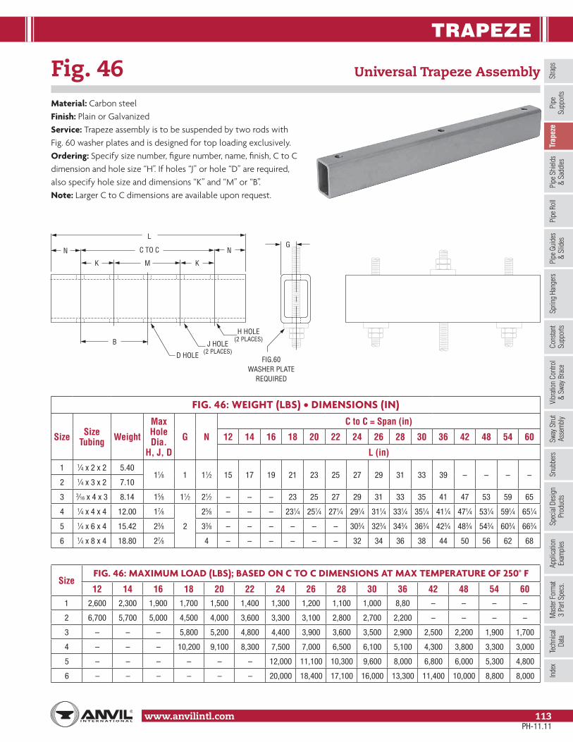
TRAPEZE
Stra
psSp
ring
Hang
ers
Cons
tant
Supp
orts
Vibr
ation
Con
trol
& Sw
ay B
race
Sway
Stru
tAs
sem
bly
Snub
bers
Appl
icatio
nEx
ampl
esSp
ecial
Des
ign
Prod
ucts
Trap
eze
Pipe
Rol
lPi
pe G
uide
s&
Slid
esPi
pe S
hield
s&
Sadd
lesPi
peSu
ppor
tsIn
dex
www.anvilintl.com 113
Tech
nica
lDa
taM
aster
For
mat
3 Pa
rt Sp
ecs.
Fig. 46 Universal Trapeze Assembly
Material: Carbon steelFinish: Plain or GalvanizedService: Trapeze assembly is to be suspended by two rods with Fig. 60 washer plates and is designed for top loading exclusively.Ordering: Specify size number, figure number, name, finish, C to C dimension and hole size “H”. If holes “J” or hole “D” are required, also specify hole size and dimensions “K” and “M” or “B”.Note: Larger C to C dimensions are available upon request.
FIG. 46: WEIGHT (LBS) • DIMENSIONS (IN)
Size Size Tubing Weight
Max Hole Dia.
H, J, D
G N
C to C = Span (in)
12 14 16 18 20 22 24 26 28 30 36 42 48 54 60
L (in)
1 1⁄4 x 2 x 2 5.4011⁄8 1 11⁄2 15 17 19 21 23 25 27 29 31 33 39 – – – –
2 1⁄4 x 3 x 2 7.10
3 3⁄16 x 4 x 3 8.14 15⁄8 11⁄2 21⁄2 – – – 23 25 27 29 31 33 35 41 47 53 59 65
4 1⁄4 x 4 x 4 12.00 17⁄8
2
25⁄8 – – – 231⁄4 251⁄4 271⁄4 291⁄4 311⁄4 331⁄4 351⁄4 411⁄4 471⁄4 531⁄4 591⁄4 651⁄4
5 1⁄4 x 6 x 4 15.42 23⁄8 33⁄8 – – – – – – 303⁄4 323⁄4 343⁄4 363⁄4 423⁄4 483⁄4 543⁄4 603⁄4 663⁄4
6 1⁄4 x 8 x 4 18.80 27⁄8 4 – – – – – – 32 34 36 38 44 50 56 62 68
SizeFIG. 46: MAXIMUM LOAD (LBS); BASED ON C TO C DIMENSIONS AT MAX TEMPERATURE OF 250° F
12 14 16 18 20 22 24 26 28 30 36 42 48 54 601 2,600 2,300 1,900 1,700 1,500 1,400 1,300 1,200 1,100 1,000 8,80 – – – –
2 6,700 5,700 5,000 4,500 4,000 3,600 3,300 3,100 2,800 2,700 2,200 – – – –
3 – – – 5,800 5,200 4,800 4,400 3,900 3,600 3,500 2,900 2,500 2,200 1,900 1,700
4 – – – 10,200 9,100 8,300 7,500 7,000 6,500 6,100 5,100 4,300 3,800 3,300 3,000
5 – – – – – – 12,000 11,100 10,300 9,600 8,000 6,800 6,000 5,300 4,800
6 – – – – – – 20,000 18,400 17,100 16,000 13,300 11,400 10,000 8,800 8,000
H HOLE(2 PLACES)
J HOLE(2 PLACES)D HOLE
B
K K
N N
M
C TO C
LG
FIG.60WASHER PLATE
REQUIRED
PH-11.11

TRAPEZE
www.anvilintl.com114
Fig. 45 Channel Assembly
Material: Carbon steelFinish: Plain or GalvanizedOrdering: Fig. 45 channel assembly; channel size, rod size, name, finish and C to C. Note: that L = (C to C) + 2M + WNote: Can also be used with a U-bolt Fig. 137 & Fig. 60 washer plates to secure pipe to the center of channel assembly.
FIG. 45: DIMENSIONS (IN)
Rod Dia
3⁄8 1⁄2 5⁄8 3⁄4 7⁄8 1 11⁄4 11⁄2 13⁄4 2 21⁄4 21⁄2 23⁄4 3 31⁄4 31⁄2
H Hole 1⁄2 5⁄8 3⁄4 7⁄8 1 11⁄4 11⁄2 13⁄4 2 21⁄4 21⁄2 23⁄4 3 31⁄4 31⁄2 33⁄4
S 9⁄16 11⁄16 13⁄16 15⁄16 11⁄16 13⁄8 15⁄8 17⁄8 21⁄4 21⁄2 23⁄4 3 31⁄4 31⁄2 33⁄4 4
W 3 3 3 4 4 4 5 5 5 5 6 6 6 6 6 7
T 1⁄4 1⁄43⁄8 3⁄8
1⁄2 1⁄2 1⁄2 3⁄4 3⁄4 3⁄4 3⁄4 3⁄4 3⁄4 3⁄4 3⁄4 3⁄4
M 3⁄8 3⁄8 3⁄8 3⁄8 3⁄8 3⁄8 3⁄8 3⁄8 3⁄8 3⁄8 3⁄8 1⁄2 1⁄2 1⁄2
Size Wt./Ft. 2C’s
FIG. 45: WEIGHTS (LBS) • LOADS (LBS) • C TO C = SPAN (IN)12 14 16 18 20 22 24 26 28 30 36 42 48 54 60
Maximum Load (lbs); Based on C to C Dimensions at Max Temperature of 250° F3 8.2 8,800 7,500 6,600 5,800 5,200 4,800 4,400 3,900 3,600 3,500 2,900 2,500 2,200 1,900 1,700
4 10.8 15,200 13,100 11,400 10,200 9,100 8,300 7,500 7,000 6,500 6,100 5,100 4,300 3,800 3,300 3,000
5 13.4 – – – 16,000 14,400 13,100 12,000 11,100 10,300 9,600 8,000 6,800 6,000 5,300 4,800
6 21.0 – – – 26,600 24,000 21,800 20,000 18,400 17,100 16,000 13,300 11,400 10,000 8,800 8,000
8 23.0 – – – – – – 32,300 29,800 27,700 25,800 21,500 18,500 16,100 14,300 12,900
10 30.6 – – – – – – 53,500 49,400 45,800 42,800 35,700 30,600 26,700 23,800 21,400
12 41.4 – – – – – – – – – – 57,000 48,900 42,800 38,000 34,200
15 67.8 – – – – – – – – – – 111,000 95,300 83,400 74,100 66,700
LM
W
C – C
TS
H DIA.W
PH-11.11
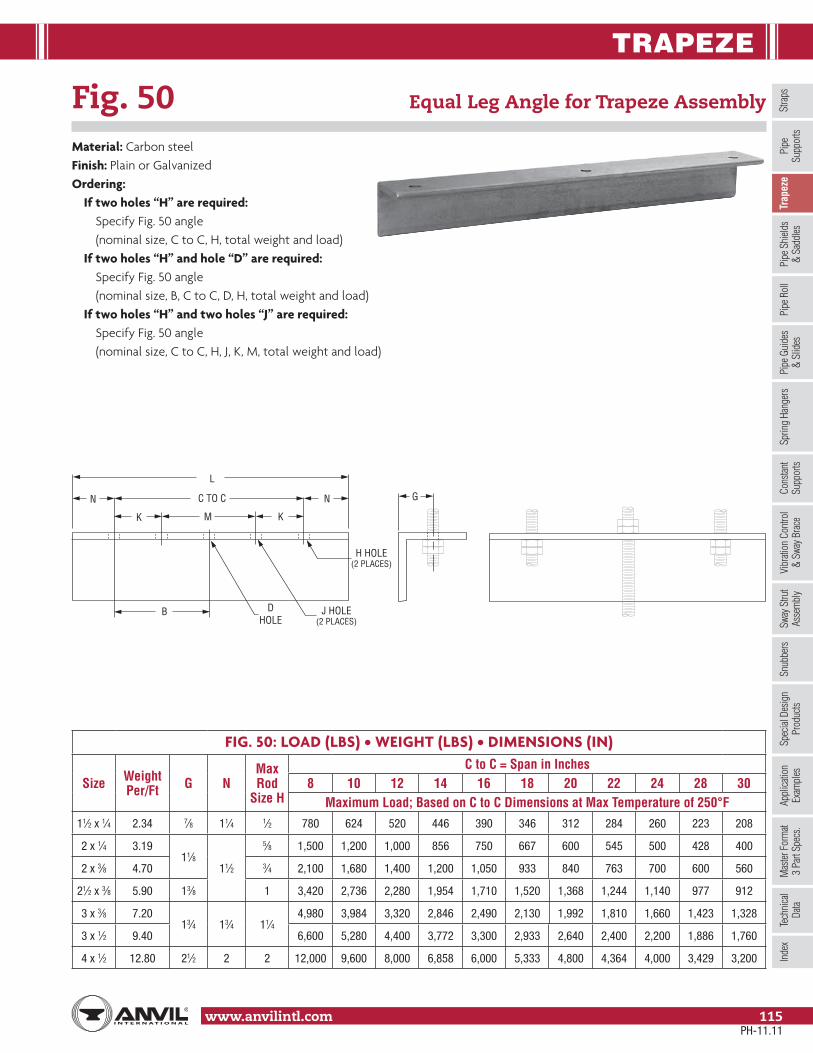
TRAPEZE
Stra
psSp
ring
Hang
ers
Cons
tant
Supp
orts
Vibr
ation
Con
trol
& Sw
ay B
race
Sway
Stru
tAs
sem
bly
Snub
bers
Appl
icatio
nEx
ampl
esSp
ecial
Des
ign
Prod
ucts
Trap
eze
Pipe
Rol
lPi
pe G
uide
s&
Slid
esPi
pe S
hield
s&
Sadd
lesPi
peSu
ppor
tsIn
dex
www.anvilintl.com 115
Tech
nica
lDa
taM
aster
For
mat
3 Pa
rt Sp
ecs.
Fig. 50 Equal Leg Angle for Trapeze Assembly
Material: Carbon steelFinish: Plain or GalvanizedOrdering:
If two holes “H” are required: Specify Fig. 50 angle (nominal size, C to C, H, total weight and load)
If two holes “H” and hole “D” are required: Specify Fig. 50 angle (nominal size, B, C to C, D, H, total weight and load)
If two holes “H” and two holes “J” are required: Specify Fig. 50 angle (nominal size, C to C, H, J, K, M, total weight and load)
FIG. 50: LOAD (LBS) • WEIGHT (LBS) • DIMENSIONS (IN)
Size Weight Per/Ft G N
Max Rod
Size H
C to C = Span in Inches8 10 12 14 16 18 20 22 24 28 30
Maximum Load; Based on C to C Dimensions at Max Temperature of 250°F11⁄2 x 1⁄4 2.34 7⁄8 11⁄4 1⁄2 780 624 520 446 390 346 312 284 260 223 208
2 x 1⁄4 3.1911⁄8
11⁄2
5⁄8 1,500 1,200 1,000 856 750 667 600 545 500 428 400
2 x 3⁄8 4.70 3⁄4 2,100 1,680 1,400 1,200 1,050 933 840 763 700 600 560
21⁄2 x 3⁄8 5.90 13⁄8 1 3,420 2,736 2,280 1,954 1,710 1,520 1,368 1,244 1,140 977 912
3 x 3⁄8 7.2013⁄4 13⁄4 11⁄4
4,980 3,984 3,320 2,846 2,490 2,130 1,992 1,810 1,660 1,423 1,328
3 x 1⁄2 9.40 6,600 5,280 4,400 3,772 3,300 2,933 2,640 2,400 2,200 1,886 1,760
4 x 1⁄2 12.80 21⁄2 2 2 12,000 9,600 8,000 6,858 6,000 5,333 4,800 4,364 4,000 3,429 3,200
H HOLE(2 PLACES)
J HOLE(2 PLACES)
DHOLE
B
K K
N N
M
C TO C
L
G
PH-11.11

PIPE SHIELDS & SADDLES
www.anvilintl.com116
Shading in gray indicates this shield fits loosely inside the Fig. 260. To be used properly, the Fig. 260 requires a spacer.
Fig. 167 Insulation Protection Shield
Size Range: 1⁄2" through 24" pipe with up to 2" thick insulationMaterial: Carbon steelFinish: GalvanizedService: Recommended for outside of foam or fiber glass insulationfor distribution of loads to preclude crushing of insulation withoutbreaking the vapor barrier.Approvals: Complies with Federal Specification A-A-1192A (Type 40), WW-H-171-E (Type 41), ANSI/MSS SP-69 and MSS SP-58 (Type 40).How to size: Refer to “shield size selection table” below.Ordering: Specify size, figure number and name. Data applicableto shields for thicker insulation or larger pipe sizes is availableupon request.
SHIELD SIZE SELECTION FOR NOMINAL PIPE SIZE
PipeSize
Insulation Thickness (in)1⁄2 3⁄4 1 11⁄2 2
1⁄21A
1A – – –3⁄4
2A 3A4A 6A
1 5A 7A11⁄4
2A 3A 4A 6A7A
11⁄2 8A2 3A 4A 5A 7A 8A
21⁄2 4A 5A 6A8A 9A
3 5A 6A 7A31⁄2 – –
8A 9A 10A4 – –5 – – 9B 10B 11B6 – – 10B 11B 12B8 – – 12B 13C 14C10 – – 14C 15C 16C12 – – 16C 17C 18C14 – – 17C 18C 19C16 – – 19C 20C 21C18 – – 21C 22C 23C20 – – 23C 24C 25C24 – – 26C 27C 28C
FIG. 167: WEIGHT (LBS) • DIMENSIONS (IN)
Shield Size Weight Stock
Size L Insulation OD Fig. 260
X1A 0.5
18 Ga.
12
1.90 11/2
1A 0.7 2.38 22A 0.8 2.88 21/2
3A 1.0 3.50 34A 1.1 4.00 31/2
5A 1.3 4.50 46A 1.4 5.00 57A 1.6 5.56 58A 1.9
16 Ga.6.64 6
9A 2.7 7.64 810A 3.1 8.64 89B 4.0
16 Ga. 18
7.64 810B 4.6 8.64 811B 5.1 9.64 1012B 5.6 10.76 1013C 10.2
14 Ga.
24
11.76 1214C 11.1 12.76 1215C 12.3 14.00 1416C 12.7 15.00 1617C 13.6 16.00 1618C 14.5 17.00 1819C 21.2
12 Ga.
18.00 1820C 22.4 19.00 2021C 23.6 20.00 2022C 24.8 21.00 2423C 25.9 22.00 2424C 27.1 23.00 2425C 28.3 24.00 2426C 31.0 26.00 3027C 31.8 27.00 3028C 33.0 28.00 30
SHIELD SIZE SELECTION FOR COPPER TUBING
Tube Size
Insulation Thickness (in)1⁄2 3⁄4 1 11⁄2 2
3⁄8X1A 1A 2A
3A 5A1⁄2, 5⁄8, 3⁄4 4A 6A1, 11⁄4 1A 2A 3A 5A 7A11⁄2 2A 3A 4A 6A
8A2 3A 4A 5A 7A21⁄2 4A 5A 6A
8A3 5A 6A 7A9A
31⁄2 6A 7A8A
4 7A8A
9A 10A5 8A 9A 10A 11B6 9A 9A 10A 11B 12B8 11B 11B 12B 13C 14C
Note: As actual foam or fiber glass insulation thicknesses vary, verify that the radius of the selected shield is suitable for the required application. Shields are designed for a maximum span of ten feet on 15 P.S.I. compressive strength insulation. For compressive strengths greater than 15 P.S.I., spans may be increased proportionately up to maximum allowable for steel pipe. Refer to MSS-SP-69 for specific guidelines on compressive strength and maximum span.
INSULATIONTHICKNESS
L
INSULATION O.D.
CL
PH-11.11

PIPE SHIELDS & SADDLES
Stra
psSp
ring
Hang
ers
Cons
tant
Supp
orts
Vibr
ation
Con
trol
& Sw
ay B
race
Sway
Stru
tAs
sem
bly
Snub
bers
Appl
icatio
nEx
ampl
esSp
ecial
Des
ign
Prod
ucts
Trap
eze
Pipe
Rol
lPi
pe G
uide
s&
Slid
esPi
pe S
hiel
ds&
Sad
dles
Pipe
Supp
orts
Inde
x
www.anvilintl.com 117
Tech
nica
lDa
taM
aster
For
mat
3 Pa
rt Sp
ecs.
Fig. 168 Rib-Lok Shield
Size Range: 1⁄2" through 8" pipe or copper tube with up to 2" insulationMaterial: Carbon steelFinish: GalvanizedApprovals: Complies with Federal Specification A-A-1192A (Type 40), WW-H-171-E (Type 41), ANSI/MSS SP-69 and MSS SP-58 (Type 40).Service: To be used with Fig. 65 or Fig. 260 clevis. Designed to prevent damage to insulation by hanger. Ribs keep shield centered in hanger.How to size: Refer to shield size selection table below.Ordering: Specify size, figure number and name.Note: Data applicable to shields for thicker insulation or larger pipe size is available upon request.
SHIELD SIZE SELECTION FOR NOMINAL PIPE SIZE
PipeSize
Insulation Thickness (in)1⁄2 3⁄4 1 11⁄2 2
1⁄2
11
– – –3⁄4 2 4 6
1 2 3 5
711⁄42 3
36
11⁄2 4
2 3 4 57 8
21⁄2 4 5 6
3 5 6 7 8 9
31⁄2
– –
8 9 104
5 9 10 11
6 10 11 12
8 12 13 14
FIG. 168: WEIGHT (LBS) • DIMENSIONS (IN)
Shield Size
Max O.D. of Insulation
Stock Sizes Weight Fig. 260
1 23⁄8
18 ga. x 8
0.41 2
2 27⁄8 0.50 21⁄2
3 31⁄2 0.61 3
4 4 0.69 31⁄2
5 41⁄2 0.78 4
6 5 0.99 5
7 55⁄8 1.09 5
8 65⁄8 1.28 6
9 75⁄8
18 ga. x 12
1.51 8
10 85⁄8 2.24 8
11 95⁄8 2.48 10
12 103⁄4 2.76 10
13 113⁄4 3.03 12
14 123⁄4 3.28 12
SHIELD SIZE SELECTION FOR COPPER TUBING
TubeSize
Insulation Thickness (in)1⁄2 3⁄4 1 11⁄2 2
3⁄8–
1 2 3 51⁄2, 5⁄8 1 2 4 6
11 2 3 5
711⁄4
11⁄2 2 3 4 6
2 3 4 57 8
21⁄2 4 5 6
3 5 67 8 9
31⁄2 67
4 7 8 9 10
5 8 8 9 10 11
6 9 9 10 11 12
8 11 11 12 13 14
INSULATION O.D.
INSULATIONTHICKNESS
2"
CL
Shading in gray indicates this shield fits loosely inside the Fig. 260. To be used properly, the Fig. 260 requires a spacer.
PH-11.11

PIPE SHIELDS & SADDLES
www.anvilintl.com118
Pipe Covering Protection SaddleFor Nominal Thickness of Covering Shown
Fig. 160: 1" Fig. 161: 11⁄2" Fig. 162: 2"Fig. 163: 21⁄2" Fig. 164: 3" Fig. 165: 4"Fig. 165A: 4" (Alloy) Fig. 166A: 51⁄2" (Alloy)
Size Range: 3⁄4" through 36"Material:
• Figs. 160, 161, 162, 163, 164, and 165 are curved carbon steel plate.• Figs. 165A and 166A are alloy steel manufactured from ASTM A 387 Grade 22 Chrome Molybdenum steel plate.• Figs. 165A and 166A have a welded-in center plate in all sizes.• All other saddles have a welded-in center plate for pipe sizes 12" and larger.• All saddles are 12" long with side edges turned up.
Finish: PlainService: Designed for use on insulated high temperature systems where heatlosses are to be kept to a minimum and to protect insulation against damage.Maximum Temperature: 650° F carbon steel, 950° F alloy steel.Approvals: Complies with Federal Specification A-A-1192A (Type 39A & 39B), WW-H-171-E (Type 40A & 40B), ANSI/MSS SP-69 and MSS SP-58 (Type 39A & 39B).Features: Permits finished, weather tight covering at all points of pipe support.Ordering: Specify pipe size, figure number and name. Data for 42" size available on request.Installation: It is recommended that saddle be welded to the pipe.
Continued on Following Page.
CD
CL
EC
CL
PH-11.11

PIPE SHIELDS & SADDLES
Stra
psSp
ring
Hang
ers
Cons
tant
Supp
orts
Vibr
ation
Con
trol
& Sw
ay B
race
Sway
Stru
tAs
sem
bly
Snub
bers
Appl
icatio
nEx
ampl
esSp
ecial
Des
ign
Prod
ucts
Trap
eze
Pipe
Rol
lPi
pe G
uide
s&
Slid
esPi
pe S
hiel
ds&
Sad
dles
Pipe
Supp
orts
Inde
x
www.anvilintl.com 119
Tech
nica
lDa
taM
aster
For
mat
3 Pa
rt Sp
ecs.
Fig. 160 to Fig 166A Pipe Covering Protection Saddle (cont.)
FIG. 160, 161, 162, 163, 164, 165, 165A, 166A: LOADS (LBS) • WEIGHT (LBS) • DIMENSIONS (IN)
Pipe Size
Fig. No.
Max Load ■ Weight
Size of Pipe Roll Center Line of Pipe to Outside of Saddle C
Center Line of Pipe to Center Line of Roll
Figs. 171, 175, 177
Figs. 174, 181
Figs. 271, 274, 277
D E
Figs. 171, 175, 177
Figs. 174, 181
Figs. 271, 274, 277
3⁄4 1,2001.4 2 21⁄2
2-31⁄215⁄8 21⁄16 21⁄8 21⁄4
2.1 3 31⁄2 23⁄16 23⁄4 23⁄4 27⁄82.8 4 5 211⁄16 35⁄16 35⁄16 33⁄8
1 1,2001.4 21⁄2 3
2-31⁄2113⁄16 25⁄16 21⁄4 27⁄16
2.1 3 4 25⁄16 27⁄8 27⁄8 32.8 4 5 27⁄8 31⁄2 31⁄2 31⁄2
11⁄4
160
1,200
1.4 21⁄2 32-31⁄2
115⁄16 21⁄2 27⁄16 29⁄16
2.1 31⁄25
29⁄16 31⁄16 31⁄16 33⁄16
2.8 4 3 35⁄8 35⁄8 311⁄16
3.6 5 6 4-6 33⁄4 43⁄8 43⁄8 43⁄8
11⁄2
160
1,200
1.5 3 31⁄22-31⁄2
21⁄8 25⁄8 25⁄8 211⁄16
2.1 31⁄2 5 25⁄8 31⁄4 31⁄4 35⁄16
3.2 5 64-6
35⁄16 4 4 37⁄83.6 6 8 37⁄8 41⁄2 45⁄8 41⁄2
2
160
1,200
1.7 31⁄2 42-31⁄2
23⁄8 3 215⁄16 31⁄16
2.3 4 5 27⁄8 31⁄2 31⁄2 39⁄16
3.2 5 64-6
39⁄16 41⁄4 41⁄4 43⁄16
3.6 68
41⁄16 43⁄4 413⁄16 43⁄44.5 8 49⁄16 53⁄8 53⁄8 51⁄4
21⁄2
160
1,200
1.7 31⁄2 5 2-31⁄2 211⁄16 31⁄4 31⁄4 35⁄16
161 2.8 5 6
4-6
35⁄16 4 4 315⁄16
162 3.2 68
37⁄8 41⁄2 45⁄8 41⁄2163 4.1
841⁄4 51⁄8 51⁄8 5
164 4.5 10 47⁄8 55⁄8 53⁄4 51⁄2
3
160
1,200
1.9 4 5 2-31⁄2 215⁄16 31⁄2 31⁄2 39⁄16
161 2.8 5 64-6
35⁄8 45⁄16 45⁄16 41⁄4162 3.6 6
841⁄8 413⁄16 413⁄16 411⁄16
163 4.18
411⁄16 57⁄16 57⁄16 55⁄16
164 4.9 10 8-10 51⁄16 6 6 61⁄16
31⁄2
160
1,200
2.3 5 64-6
35⁄16 4 4 315⁄16
161 3.2 68
311⁄16 49⁄16 49⁄16 41⁄2162 3.6
845⁄16 51⁄8 51⁄8 5
163 4.510 8-10
411⁄16 55⁄8 55⁄8 511⁄16
164 4.9 10 53⁄8 65⁄16 65⁄16 63⁄8
4
160
1,200
2.3 5 64-6
39⁄16 41⁄4 41⁄4 43⁄16
161 3.2 68
41⁄16 47⁄8 47⁄8 43⁄4162 3.6
849⁄16 53⁄8 53⁄8 51⁄4
163 4.510 8-10
5 515⁄16 515⁄16 6164 4.9
1055⁄8 69⁄16 69⁄16 65⁄8
165 6.112
12-1461⁄2 75⁄8 75⁄8 79⁄16
165A7,200
11.6166A 15.7 14 16 81⁄8 95⁄8 91⁄2 95⁄16
■ Maximum recommended loads are applicable only when saddle is used on a flat bearing surface or roller hangers and tack welded to pipe. When saddle is used with a pipe roll, the maximum load for the assembly is the smaller of the two loads.
Continued on Following Page.
PH-11.11

PIPE SHIELDS & SADDLES
www.anvilintl.com120
Fig. 160 to Fig 166A Pipe Covering Protection Saddle (cont.)
FIG. 160, 161, 162, 163, 164, 165, 165A, 166A: LOADS (LBS) • WEIGHT (LBS) • DIMENSIONS (IN)
Pipe Size
Fig. No.
Max Load ■ Weight
Size of Pipe Roll Center Line of Pipe to Outside of Saddle C
Center Line of Pipe to Center Line of Roll
Figs. 171, 175, 177
Figs. 174, 181
Figs. 271, 274, 277
D E
Figs. 171, 175, 177
Figs. 174, 181
Figs. 271, 274, 277
5
160
1,200
2.3 68 4-6
41⁄8 413⁄16 413⁄16 43⁄4161 3.2
8411⁄16 51⁄2 51⁄2 53⁄8
162 3.610
8-1053⁄16 6 61⁄16 61⁄8
163 4.510
55⁄8 69⁄16 69⁄16 65⁄8164 4.9 12 63⁄16 71⁄8 71⁄4 71⁄4165 6.1
12 1412-14
71⁄883⁄16
83⁄8 83⁄16165A
7,20011.6 81⁄8
166A 15.7 16 16 811⁄16 101⁄16 101⁄16 97⁄8
6
160
1,800
3.88
8 4-6 41⁄2 53⁄8 53⁄8 51⁄4161 4.4
108-10 51⁄16 57⁄8 511⁄16 6
162 5.710
8-1051⁄2 67⁄16 67⁄16 61⁄2
163 6.512
63⁄16 71⁄8 73⁄16 71⁄4164 7.7 12 69⁄16 75⁄8 75⁄8 75⁄8165 10.2
14 16 12-1479⁄16 9
983⁄4
165A7,200
12.9 75⁄8 91⁄8 813⁄16
166A 16.3 16 18 16-20 91⁄8 105⁄8 109⁄16 107⁄16
8
161
1,800
5.810 12
8-106 71⁄16 71⁄16 71⁄16
162 6.3 61⁄2 79⁄16 79⁄16 79⁄16
163 7.2 12 14 71⁄4 85⁄16 81⁄2 85⁄16
164 7.7 14 16 12-14 711⁄16 9 9 83⁄4165 10.2
16 1816-20
811⁄16101⁄8
101⁄8 97⁄8165A
7,20016.9 101⁄16
166A 22.6 18 20 101⁄4 117⁄8 1113⁄16 115⁄8
10
161
1,800
5.8 12 14 8–10 71⁄4 85⁄16 81⁄2 85⁄16
162 7.714 16 12-14
75⁄8 91⁄16 9 813⁄16
163 8.2 81⁄8 99⁄16 99⁄16 95⁄16
164 8.8 16 1816-20
811⁄16 101⁄8 101⁄16 10165 10.8
18 2093⁄4 111⁄4
111⁄4 111⁄8165A
7,20018.9 911⁄16 115⁄16
166A 24.3 20 – 22-24 111⁄8 1215⁄16 – 121⁄2
12
161
5,000
7.8 14 16 12-14 81⁄16 91⁄2 91⁄2 91⁄4162 9.9
16 18
16-20
85⁄8 103⁄16 101⁄16 10163 10.5 91⁄8 1011⁄16 109⁄16 101⁄2164 11.4 18 20 95⁄8 111⁄8 111⁄8 11165 14.0
20– 1013⁄16 123⁄8 – 123⁄16
165A11,140
28.0 – 11 121⁄2 – 123⁄8166A 35.5 24 – 22-24 125⁄16 141⁄4 – 1311⁄16
14
161
5,000
7.816 18
12-14 83⁄4 103⁄16 101⁄8 101⁄16
162 9.916-20
95⁄16 107⁄8 1013⁄16 1011⁄16
163 10.518 20
97⁄8 115⁄16 113⁄8 113⁄16
164 11.4 105⁄16 113⁄4 113⁄4 115⁄8165 14.0
20–
22-24115⁄16 127⁄8 – 125⁄8
165A11,140
27.6 – 119⁄16 131⁄16 – 127⁄8166A 35.5 24 – 127⁄8 143⁄4 – 141⁄4
■ Maximum recommended loads are applicable only when saddle is used on a flat bearing surface or roller hangers and tack welded to pipe. When saddle is used with a pipe roll, the maximum load for the assembly is the smaller of the two loads.
Continued on Following Page.
PH-11.11

PIPE SHIELDS & SADDLES
Stra
psSp
ring
Hang
ers
Cons
tant
Supp
orts
Vibr
ation
Con
trol
& Sw
ay B
race
Sway
Stru
tAs
sem
bly
Snub
bers
Appl
icatio
nEx
ampl
esSp
ecial
Des
ign
Prod
ucts
Trap
eze
Pipe
Rol
lPi
pe G
uide
s&
Slid
esPi
pe S
hiel
ds&
Sad
dles
Pipe
Supp
orts
Inde
x
www.anvilintl.com 121
Tech
nica
lDa
taM
aster
For
mat
3 Pa
rt Sp
ecs.
Fig. 160 to Fig 166A Pipe Covering Protection Saddle (cont.)
FIG. 160, 161, 162, 163, 164, 165, 165A, 166A: LOADS (LBS) • WEIGHT (LBS) • DIMENSIONS (IN)
Pipe Size
Fig. No.
Max Load ■ Weight
Size of Pipe Roll Center Line of Pipe to Outside of Saddle C
Center Line of Pipe to Center Line of Roll
Figs. 171, 175, 177
Figs. 174, 181
Figs. 271, 274, 277
D E
Figs. 171, 175, 177
Figs. 174, 181
Figs. 271, 274, 277
16
1615,000
8.418 20
16-20913⁄16 111⁄4 111⁄4 111⁄8
162 10.4 103⁄16 113⁄16 113⁄4 119⁄16
1637,200
11.1 20 – 1013⁄16 125⁄16 – 123⁄16
164 13.324
–22-24
111⁄16 127⁄8 – 127⁄16
165 15.3 – 123⁄16 141⁄8 – 135⁄8165A
11,14030.1 – 127⁄16 145⁄16 – 137⁄8
166A 40.0 30 – 26-30 1313⁄16 165⁄8 – 155⁄8
18
161 5,000 9.120
– 16-20 1013⁄16 125⁄16 – 123⁄16
162
7,200
10.4 –
22-24
115⁄16 127⁄8 – 1211⁄16
163 12.4
24
– 115⁄8 139⁄16 – 131⁄16
164 13.3 – 121⁄4 143⁄16 – 135⁄8165 15.3 – 135⁄16 151⁄4 – 143⁄4
165A13,370
40.3 – 133⁄4 1511⁄16 – 151⁄8166A 52.1 30 – 26-30 147⁄8 175⁄8 – 165⁄8
20
161
7,200
10.4
24
–
22-24
115⁄8 139⁄16 – 131⁄16
162 11.6 – 121⁄4 141⁄8 – 135⁄8163 12.4 – 123⁄4 1411⁄16 – 143⁄16
164 13.4 – 135⁄16 151⁄4 – 143⁄4165 22.8
30–
26-30141⁄8 17 – 157⁄8
165A13,370
44.8 – 143⁄8 173⁄16 – 161⁄8166A 52.1 – 161⁄8 1815⁄16 – 177⁄8
24
161
7,200
12.3
30
–
26-30
131⁄2 165⁄16 – 151⁄4162 13.4 – 14 167⁄8 – 153⁄4163 14.3 – 145⁄8 171⁄2 – 167⁄16
164 20.3 – 151⁄4 181⁄16 – 17165 23.1 – 167⁄16 191⁄4 – 183⁄16
165A13,370
45.4 – 1611⁄16 191⁄2 – 187⁄16
166A 52.1 – – 18 – – 193⁄4
30
161
7,200
13.3 – –
36-42
1615⁄16 – – 187⁄8162 14.0 – – 171⁄2 – – 193⁄8163 20.0 – – 181⁄16 – – 1915⁄16
164 21.4 – – 185⁄8 – – 201⁄2165 24.0 – – 1911⁄16 – – 211⁄2
165A13,370
47.9 – – 1915⁄16 – – 213⁄4166A 55.6 – – 211⁄2 – – 233⁄8
36
161
7,200
18.0 – –
36-42
201⁄4 – – 221⁄8162 18.9 – – 2015⁄16 – – 225⁄8163 20.2 – – 215⁄16 – – 233⁄16
164 21.6 – – 217⁄8 – – 2311⁄16
165 24.1 – – 227⁄8 – – 2411⁄16
165A13,370
48.3 – – 231⁄8 – – 25166A 55.8 – – 245⁄8 – – 261⁄2
■ Maximum recommended loads are applicable only when saddle is used on a flat bearing surface or roller hangers and tack welded to pipe. When saddle is used with a pipe roll, the maximum load for the assembly is the smaller of the two loads.
PH-11.11

PIPE ROLL
www.anvilintl.com122
Fig. 177 Adjustable Pipe Roll Support
Size Range: 1" through 30"Material: Cast iron roll and sockets; steel roll rod, continuous thread rodsand hex nutsFinish: Plain, Galvanized or Resilient CoatedService: For support of pipe where longitudinal movement due toexpansion and contraction will occur and where vertical adjustment up to 6"may be necessary.Maximum Temperature: 450° F at roller, 300˚ F at Resilent coated roller.Approvals: Complies with Federal Specification A-A-1192A (Type 41), WW-H-171-E (Type 42), ANSI/MSS SP-69 and MSS SP-58 (Type 41).Installation: Normally used directly above steel beams, brackets angles, etc.Features: Advantages of pipe rollers with a protective resilient coated covering.
• Non conductive pipe rollers - prevent the passing of current from pipeline to structure.• Corrosion resistant - for protection against severe weather conditions, moderate corrosive conditions such as marine atmospheres and weather resistant to ultra-violet radiation.• Low coefficient of friction between pipe and resilient coated pipe roller.
How to size:(1) If roll is to support bare pipe, select the size directly from nominal pipe size (see below).(2) If used with pipe covering protection saddle, see page 118 for size of pipe roll.(3) If roll is to support covered pipe, the O.D. of the covering should not be greater than the O.D. of the pipe for which
the roll was designed.Ordering: Specify size of roll, figure number and name. Be certain to order oversized rolls when insulation and protection saddles makes this necessary.
FIG. 177: WEIGHT (LBS) • DIMENSIONS (IN)PipeSize Weight A B C D H
1 1.1
3⁄8
3 11⁄2
12
11⁄16
11⁄4 1.2 33⁄8 17⁄8 11⁄4
11⁄2 1.2 35⁄8 21⁄8 13⁄8
2 1.3 41⁄8 25⁄8 15⁄8
21⁄2 2.31⁄2
47⁄8 31⁄8 115⁄16
3 2.4 51⁄2 33⁄4 21⁄4
31⁄2 2.7 61⁄8 41⁄4 29⁄16
4 3.85⁄8
67⁄8 43⁄4 213⁄16
5 4.7 81⁄16 513⁄16 37⁄16
6 7.63⁄4
99⁄16 67⁄8 4
8 11.0 1115⁄16 87⁄8 51⁄8
10 13.77⁄8
141⁄16 11 63⁄8
12 19.4 1513⁄16 121⁄2 77⁄16
14 31.2
1
173⁄4 141⁄4 83⁄8
16 42.5 193⁄4 161⁄4
18
97⁄16
18 46.6 217⁄8 181⁄4 101⁄2
20 66.2 11⁄4 241⁄4 201⁄4 115⁄8
24 102.511⁄2
287⁄8 241⁄424
14
30 186.8 351⁄2 301⁄4 177⁄16
A
B
D
H
C
CL
DI/CI ROLL SIZING
DI/CIPipeSize
Fig. 177 Roller Size
3 4
4 5
6 6
8 8
10 10
12 14
14 16
16 18
18 20
20 24
24 30
30 No Recom.
PH-11.11

PIPE ROLL
Stra
psSp
ring
Hang
ers
Cons
tant
Supp
orts
Vibr
ation
Con
trol
& Sw
ay B
race
Sway
Stru
tAs
sem
bly
Snub
bers
Appl
icatio
nEx
ampl
esSp
ecial
Des
ign
Prod
ucts
Trap
eze
Pipe
Rol
lPi
pe G
uide
s&
Slid
esPi
pe S
hield
s&
Sadd
lesPi
peSu
ppor
tsIn
dex
www.anvilintl.com 123
Tech
nica
lDa
taM
aster
For
mat
3 Pa
rt Sp
ecs.
Fig. 171: Pipe Roll Single Pipe Roll
Size Range: 1" through 30"Material: Cast iron roll and sockets, steel roll rodFinish: Plain, Galvanized or Resilient CoatedService: For suspension of pipe from two rods where longitudinal expansion and contraction may occur.Approvals: Complies with Federal Specification A-A-1192A (Type 41), WW-H-171-E (Type 42), ANSI/MSS SP-69 and MSS SP-58 (Type 41).Adjustment: Adjustable socket permits vertical adjustment at the roll.Maximum Temperature: 450° F at roller, 300˚ F at resilient coated roller.How to size:
(1) If the roll is to support non-insulated pipe, select the size directly from nominal pipe size (column 1) in table below.(2) If used with pipe covering protection saddle, see page 118 for size of pipe roll.
Features:• Provides for vertical adjustment; nut at bottom of hanger rod fits into the socket preventing loosening or turning due to vibration.• Pipe roll is designed for two point surface contact with pipe or saddle.
Features: Advantages of pipe rollers with a protective resilient coated covering.• Non conductive pipe rollers - prevent the passing of current from pipeline to structure.• Corrosion resistant - for protection against severe weather conditions, moderate corrosive conditions such as marine atmospheres and weather resistant to ultra-violet radiation.• Low coefficient of friction between pipe and resilient coated pipe roller.
Ordering:• Specify pipe roll size.• Order should include figure number, name and finish in all cases. Hanger rods and nuts to be ordered separately.• Be certain to order oversized rolls when insulation and protection saddles makes this necessary.
FIG. 171: LOADS (LBS) • WEIGHT (LBS) • DIMENSIONS (IN)
Pipe Size
Max O.D. Covering
Rod Size A
Max Load Weight G B C D E F H J
1 2
3⁄8 600
0.45 41⁄8 3 11⁄2 1
3⁄4 3⁄8
11⁄16
9⁄1611⁄4 21⁄2 0.48 41⁄2 33⁄8 17⁄8 11⁄16 11⁄411⁄2 23⁄4 0.51 43⁄4 35⁄8 21⁄8 11⁄8 13⁄82 31⁄4 0.57 51⁄4 41⁄8 25⁄8 13⁄16 15⁄8
21⁄2 33⁄41⁄2
660 1.00 61⁄4 47⁄8 31⁄8 13⁄8 7⁄81⁄2
115⁄16 11⁄163 41⁄2 700 1.10 67⁄8 51⁄2 33⁄4 17⁄16 21⁄4
31⁄2 5750
1.40 71⁄2 61⁄8 41⁄4 15⁄81
29⁄16 3⁄44 51⁄2 5⁄8
1.70 81⁄4 67⁄8 43⁄4 13⁄4 213⁄16
5 7 2.60 911⁄16 81⁄16 513⁄16 2 11⁄8 5⁄8 37⁄16 7⁄86 81⁄4 3⁄4
1,070 4.50 117⁄16 99⁄16 67⁄8 25⁄16 11⁄4 3⁄4 4 18 101⁄2 1,350 7.20 141⁄16 1115⁄16 87⁄8 213⁄16 11⁄2 7⁄8
51⁄811⁄8
10 123⁄4 7⁄81,730 9.50 163⁄16 141⁄16 11 33⁄8 13⁄4 63⁄8
12 143⁄4 2,400 15.90 1715⁄16 1513⁄16 121⁄2 37⁄8 2 1 77⁄16 11⁄414 161⁄4
13,130 24.30 201⁄8 173⁄4 141⁄4 45⁄8 21⁄2 11⁄8 83⁄8 13⁄8
16 18 3,970 31.90 221⁄8 193⁄4 161⁄4 5 25⁄811⁄4
97⁄1611⁄2
18 201⁄4 4,200 35.50 241⁄2 217⁄8 181⁄4 57⁄16 23⁄4 101⁄220 221⁄2 11⁄4 4,550 47.00 271⁄4 241⁄4 201⁄4 6 3 115⁄8 15⁄824 261⁄2
11⁄26,160 76.30 321⁄8 287⁄8 241⁄4 73⁄16 35⁄8 11⁄2 14 13⁄4
30 321⁄2 7,290 129.90 39 351⁄2 301⁄4 815⁄16 41⁄2 13⁄4 177⁄16 27⁄16
DI/CI ROLL SIZING
DI/CIPipe Size
Fig. 171 Roller Size
3 44 56 68 8
10 1012 1414 1616 1818 2020 2424 3030 No Recom.
BG
H
JC
DE
A
F
CL
PH-11.11

PIPE ROLL
www.anvilintl.com124
Fig. 178 Spring Cushion Hanger
Material: Spring cushion hanger Fig. 178 consists of a set of two springs and four cast iron retainers only.Finish: Plain (retainers), Painted (springs)Service: Generally used with Fig. 171 single pipe roll as shown in above photo. Recommended for installations where formal load and movement calculations are not required, or calculated movement does not exceed 1⁄4".Maximum Temperature: 450° F at rollerApprovals: Complies with Federal Specification A-A-1192A (Type 49),WW-H-171-E (Type 50), ANSI/MSS SP-69 and MSS SP-58 (Type 49).Ordering: Specify figure number, name and rod size. If used with Fig. 171 single pipe roll, pipe roll must be ordered separately. The retainers are casted to the dimensions as shown, but center hole can be drilled or reamed larger to satisfy the hanger rod required,up to the max rod size.
FIG. 178: LOADS (LBS) • WEIGHT (LBS) • DIMENSIONS (IN)
Spring No.
Max Spring
Deflection *
Load at Max
Deflection ■
Deflection Rate of Hanger (lbs / inch)
Weight C D Core Hole Dia.
For Rod Size
Max Rod Size **
A
1
11⁄4
535 428 4.5 221⁄32 67⁄16 7⁄16 3⁄83⁄4
2 1,500 1,200 14.0 41⁄8 61⁄16 9⁄16 1⁄2
3 3,000 2,400 22.0 41⁄8 91⁄16 15⁄16 7⁄8 11⁄2
* At maximum recommended deflection, spring can be compressed an additional 1⁄4" before becoming solid.■ Maximum capacity of double spring hanger.** Can be drilled to max. rod size.
CCLL
D
C
PH-11.11
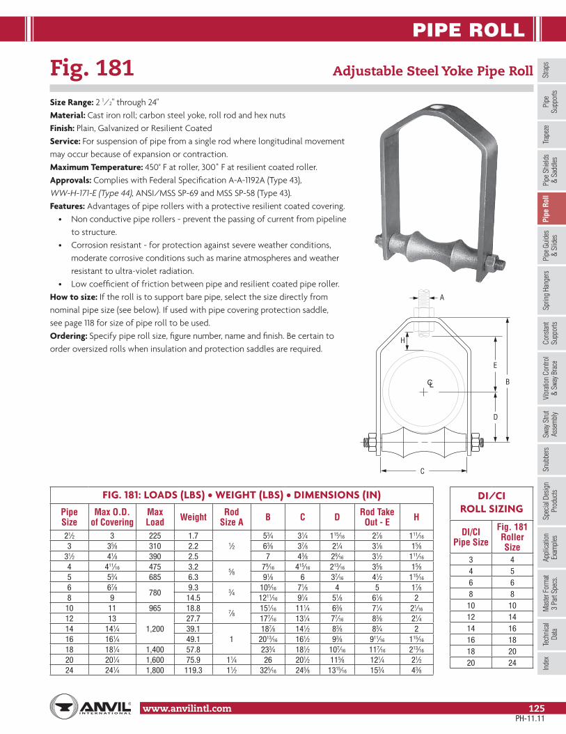
PIPE ROLL
Stra
psSp
ring
Hang
ers
Cons
tant
Supp
orts
Vibr
ation
Con
trol
& Sw
ay B
race
Sway
Stru
tAs
sem
bly
Snub
bers
Appl
icatio
nEx
ampl
esSp
ecial
Des
ign
Prod
ucts
Trap
eze
Pipe
Rol
lPi
pe G
uide
s&
Slid
esPi
pe S
hield
s&
Sadd
lesPi
peSu
ppor
tsIn
dex
www.anvilintl.com 125
Tech
nica
lDa
taM
aster
For
mat
3 Pa
rt Sp
ecs.
Fig. 181 Adjustable Steel Yoke Pipe Roll
Size Range: 2 1⁄2" through 24"Material: Cast iron roll; carbon steel yoke, roll rod and hex nutsFinish: Plain, Galvanized or Resilient CoatedService: For suspension of pipe from a single rod where longitudinal movementmay occur because of expansion or contraction.Maximum Temperature: 450° F at roller, 300˚ F at resilient coated roller.Approvals: Complies with Federal Specification A-A-1192A (Type 43), WW-H-171-E (Type 44), ANSI/MSS SP-69 and MSS SP-58 (Type 43).Features: Advantages of pipe rollers with a protective resilient coated covering.
• Non conductive pipe rollers - prevent the passing of current from pipeline to structure.• Corrosion resistant - for protection against severe weather conditions, moderate corrosive conditions such as marine atmospheres and weather resistant to ultra-violet radiation.• Low coefficient of friction between pipe and resilient coated pipe roller.
How to size: If the roll is to support bare pipe, select the size directly fromnominal pipe size (see below). If used with pipe covering protection saddle,see page 118 for size of pipe roll to be used.Ordering: Specify pipe roll size, figure number, name and finish. Be certain toorder oversized rolls when insulation and protection saddles are required.
FIG. 181: LOADS (LBS) • WEIGHT (LBS) • DIMENSIONS (IN)
Pipe Size
Max O.D. of Covering
Max Load Weight Rod
Size A B C D Rod Take Out - E H
21⁄2 3 225 1.71⁄2
53⁄4 31⁄4 115⁄16 27⁄8 111⁄16
3 35⁄8 310 2.2 63⁄8 37⁄8 21⁄4 31⁄8 15⁄831⁄2 41⁄8 390 2.5 7 43⁄8 29⁄16 31⁄2 111⁄16
4 411⁄16 475 3.2 5⁄879⁄16 415⁄16 213⁄16 35⁄8 15⁄8
5 53⁄4 685 6.3 91⁄8 6 37⁄16 41⁄2 115⁄16
6 67⁄8780
9.3 3⁄4105⁄16 71⁄8 4 5 17⁄8
8 9 14.5 1211⁄16 91⁄4 51⁄8 61⁄8 210 11 965 18.8 7⁄8
151⁄16 111⁄4 63⁄8 71⁄4 21⁄16
12 131,200
27.7 177⁄16 131⁄4 77⁄16 83⁄8 21⁄414 141⁄4 39.1
1187⁄8 141⁄2 83⁄8 83⁄4 2
16 161⁄4 49.1 2013⁄16 161⁄2 93⁄8 911⁄16 115⁄16
18 181⁄4 1,400 57.8 233⁄4 181⁄2 107⁄16 117⁄16 213⁄16
20 201⁄4 1,600 75.9 11⁄4 26 201⁄2 115⁄8 121⁄4 21⁄224 241⁄4 1,800 119.3 11⁄2 325⁄16 245⁄8 1315⁄16 153⁄4 43⁄8
DI/CI ROLL SIZING
DI/CI Pipe Size
Fig. 181 Roller Size
3 44 56 68 8
10 1012 1414 1616 1818 2020 24
A
B
D
E
C
H
CL
PH-11.11

PIPE ROLL
www.anvilintl.com126
Fig. 175 Roller Chair
Size Range: 2" through 30" pipeMaterial: Cast iron roll, steel chair, roll rod, bolts and hex nutsFinish: Plain, Galvanized or Resilient CoatedMaximum Temperature: 450° F at roller, 300˚ F at resilient coated roller.Service: For support of pipe where longitudinal movement due toexpansion and contraction may occur, but where no verticaladjustment is required.Approvals: Complies with Federal Specification A-A-1192A (Type 44), WW-H-171-E (Type 45), ANSI/MSS SP-69 and MSS SP-58 (Type 44).Installation: Two bolts and nuts provide anchorage to floor or top of steel beam or bracket or chair may be welded to supporting steel.Features: Advantages of pipe rollers with a protective resilient coated covering.
• Non conductive pipe rollers - prevent the passing of current from pipeline to structure.• Corrosion resistant - for protection against severe weather conditions, moderate corrosive conditions such as marine atmospheres and weather resistant to ultra-violet radiation.• Low coefficient of friction between pipe and resilient coated pipe roller.
How to size:(1) If roll is to support bare pipe, select the size directly from
nominal pipe size (see below).(2) If used with pipe covering protection saddle, see page 118 for size of pipe roll.(3) If roll is to support covered pipe, the O.D. of the covering should not be
greater than the O.D. of the pipe for which the roll was designed.Ordering: Specify size of roll, figure number, name and finish. Be certain to orderoversized rolls when insulation and protection saddles are required.
FIG. 175: LOADS (LBS) • WEIGHT (LBS) • DIMENSIONS (IN)
PipeSize
MaxLoad Weight W B C F G
Width H
2 600 1.1 411⁄4
11⁄2
3⁄8 x 11⁄211/4
15⁄821⁄2 660 1.4 47⁄8 15⁄8 115⁄16
3 700 1.6 53⁄82
13⁄4 21⁄431⁄2
7502.6 61⁄8 21⁄16
11/2
29⁄16
4 2.9 65⁄8 25⁄16
1⁄2 x 11⁄2213⁄16
5 3.7 77⁄8 3 21⁄2 37⁄16
6 1,070 5.9 91⁄4 31⁄8 23⁄4
2
48 1,350 9.0 115⁄8 33⁄8 3 5⁄8 x 11⁄2 51⁄8
10 1,730 13.8 141⁄8 51⁄4 35⁄8 5⁄8 x 263⁄8
12 2,400 18.9 161⁄8 51⁄2 41⁄8 77⁄16
14 3,130 28.07 183⁄4 61⁄2 411⁄16 3⁄4 x 2 21/2 83⁄816 3,970 34.93 21 81⁄4 53⁄8
3⁄4 x 21⁄2 393⁄8
18 4,200 44.35 231⁄8 91⁄4 6 107⁄16
20 4,550 56.34 245⁄8 101⁄4 61⁄2 115⁄824 6,160 87.52 293⁄8 121⁄4 77⁄8 7⁄8 x 31⁄2
4 1430 7,290 151.25 3413⁄16 153⁄8 83⁄4 6 177⁄16
W
B
F
C
H
CL
G
DI/CI ROLL SIZING
DI/CIPipe Size
Fig. 175 Roller Size
3 44 56 68 8
10 1012 1414 1616 1818 2020 2424 3030 No Recom.
PH-11.11
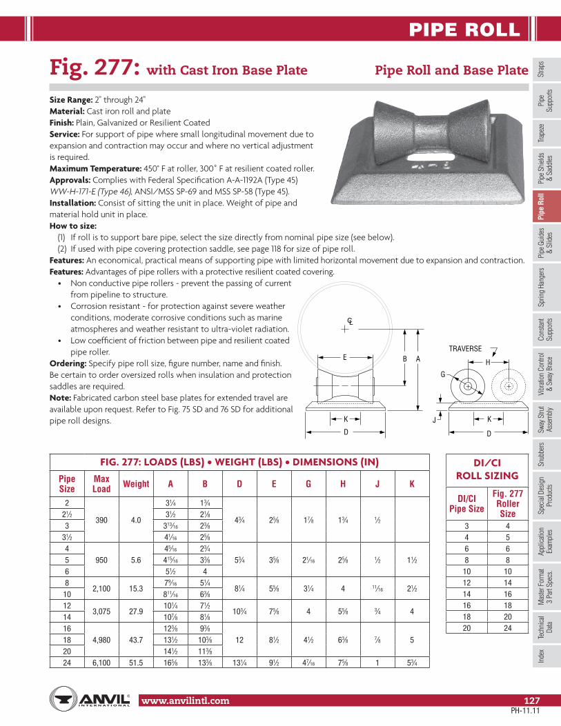
PIPE ROLL
Stra
psSp
ring
Hang
ers
Cons
tant
Supp
orts
Vibr
ation
Con
trol
& Sw
ay B
race
Sway
Stru
tAs
sem
bly
Snub
bers
Appl
icatio
nEx
ampl
esSp
ecial
Des
ign
Prod
ucts
Trap
eze
Pipe
Rol
lPi
pe G
uide
s&
Slid
esPi
pe S
hield
s&
Sadd
lesPi
peSu
ppor
tsIn
dex
www.anvilintl.com 127
Tech
nica
lDa
taM
aster
For
mat
3 Pa
rt Sp
ecs.
Fig. 277: with Cast Iron Base Plate Pipe Roll and Base Plate
Size Range: 2" through 24"Material: Cast iron roll and plateFinish: Plain, Galvanized or Resilient CoatedService: For support of pipe where small longitudinal movement due toexpansion and contraction may occur and where no vertical adjustmentis required.Maximum Temperature: 450° F at roller, 300˚ F at resilient coated roller.Approvals: Complies with Federal Specification A-A-1192A (Type 45) WW-H-171-E (Type 46), ANSI/MSS SP-69 and MSS SP-58 (Type 45).Installation: Consist of sitting the unit in place. Weight of pipe and material hold unit in place.How to size:
(1) If roll is to support bare pipe, select the size directly from nominal pipe size (see below).(2) If used with pipe covering protection saddle, see page 118 for size of pipe roll.
Features: An economical, practical means of supporting pipe with limited horizontal movement due to expansion and contraction.Features: Advantages of pipe rollers with a protective resilient coated covering.
• Non conductive pipe rollers - prevent the passing of current from pipeline to structure.• Corrosion resistant - for protection against severe weather conditions, moderate corrosive conditions such as marine atmospheres and weather resistant to ultra-violet radiation.• Low coefficient of friction between pipe and resilient coated pipe roller.
Ordering: Specify pipe roll size, figure number, name and finish.Be certain to order oversized rolls when insulation and protectionsaddles are required.Note: Fabricated carbon steel base plates for extended travel areavailable upon request. Refer to Fig. 75 SD and 76 SD for additionalpipe roll designs.
E B
D
A
J
G
K
D
K
H
TRAVERSE
CL
FIG. 277: LOADS (LBS) • WEIGHT (LBS) • DIMENSIONS (IN)
Pipe Size
Max Load Weight A B D E G H J K
2
390 4.0
31⁄4 13⁄4
43⁄4 25⁄8 17⁄8 13⁄4 1⁄221⁄2 31⁄2 21⁄83 313⁄16 23⁄8
31⁄2 41⁄16 25⁄84
950 5.645⁄16 23⁄4
53⁄4 35⁄8 21⁄16 25⁄8 1⁄2 11⁄25 415⁄16 33⁄86 51⁄2 48
2,100 15.379⁄16 51⁄4
81⁄4 55⁄8 31⁄4 4 11⁄16 21⁄210 811⁄16 63⁄812
3,075 27.9101⁄4 71⁄2
103⁄4 75⁄8 4 55⁄8 3⁄4 414 107⁄8 81⁄816
4,980 43.7123⁄8 93⁄8
12 81⁄2 41⁄2 63⁄8 7⁄8 518 131⁄2 103⁄820 141⁄2 113⁄824 6,100 51.5 165⁄8 133⁄8 131⁄4 91⁄2 47⁄16 75⁄8 1 53⁄4
DI/CI ROLL SIZING
DI/CI Pipe Size
Fig. 277 Roller Size
3 44 56 68 8
10 1012 1414 1616 1818 2020 24
PH-11.11
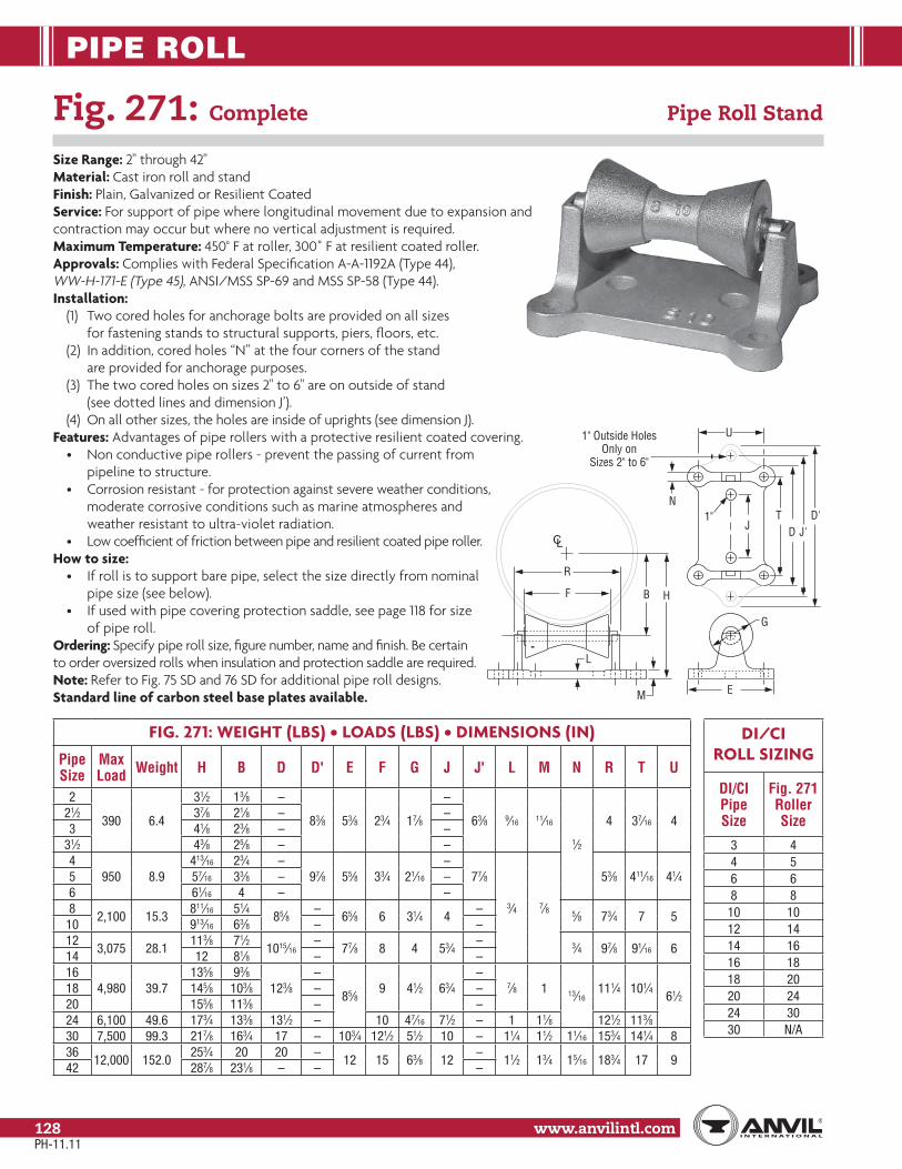
PIPE ROLL
www.anvilintl.com128
Fig. 271: Complete Pipe Roll Stand
Size Range: 2" through 42"Material: Cast iron roll and standFinish: Plain, Galvanized or Resilient CoatedService: For support of pipe where longitudinal movement due to expansion andcontraction may occur but where no vertical adjustment is required.Maximum Temperature: 450° F at roller, 300˚ F at resilient coated roller.Approvals: Complies with Federal Specification A-A-1192A (Type 44), WW-H-171-E (Type 45), ANSI/MSS SP-69 and MSS SP-58 (Type 44).Installation:
(1) Two cored holes for anchorage bolts are provided on all sizes for fastening stands to structural supports, piers, floors, etc.
(2) In addition, cored holes “N” at the four corners of the stand are provided for anchorage purposes.
(3) The two cored holes on sizes 2" to 6" are on outside of stand (see dotted lines and dimension J’).
(4) On all other sizes, the holes are inside of uprights (see dimension J).Features: Advantages of pipe rollers with a protective resilient coated covering.
• Non conductive pipe rollers - prevent the passing of current from pipeline to structure.• Corrosion resistant - for protection against severe weather conditions, moderate corrosive conditions such as marine atmospheres and weather resistant to ultra-violet radiation.• Low coefficient of friction between pipe and resilient coated pipe roller.
How to size:• If roll is to support bare pipe, select the size directly from nominal pipe size (see below).• If used with pipe covering protection saddle, see page 118 for size of pipe roll.
Ordering: Specify pipe roll size, figure number, name and finish. Be certainto order oversized rolls when insulation and protection saddle are required.Note: Refer to Fig. 75 SD and 76 SD for additional pipe roll designs.Standard line of carbon steel base plates available.
D'J'
T
B H
1" Outside HolesOnly on
Sizes 2" to 6"
J1"
L
F
M
R
E
U
N
G
CLD
FIG. 271: WEIGHT (LBS) • LOADS (LBS) • DIMENSIONS (IN)
Pipe Size
Max Load Weight H B D D' E F G J J' L M N R T U
2
390 6.4
31⁄2 13⁄8 –
83⁄8 53⁄8 23⁄4 17⁄8
–
63⁄8 9⁄16 11⁄16
1⁄2
4 37⁄16 421⁄2 37⁄8 21⁄8 – –3 41⁄8 23⁄8 – –
31⁄2 43⁄8 25⁄8 – –4
950 8.9413⁄16 23⁄4 –
97⁄8 55⁄8 33⁄4 21⁄16
–77⁄8
3⁄4 7⁄8
53⁄8 411⁄16 41⁄45 57⁄16 33⁄8 – –6 61⁄16 4 – –8
2,100 15.3811⁄16 51⁄4
85⁄8–
65⁄8 6 31⁄4 4– 5⁄8 73⁄4 7 5
10 913⁄16 63⁄8 – –12
3,075 28.1113⁄8 71⁄2
1015⁄16–
77⁄8 8 4 53⁄4– 3⁄4 97⁄8 91⁄16 6
14 12 81⁄8 – –16
4,980 39.7135⁄8 93⁄8
123⁄8–
85⁄89 41⁄2 63⁄4
–7⁄8 1 13⁄16
111⁄4 101⁄461⁄2
18 145⁄8 103⁄8 – –20 155⁄8 113⁄8 – –24 6,100 49.6 173⁄4 133⁄8 131⁄2 – 10 47⁄16 71⁄2 – 1 11⁄8 121⁄2 113⁄830 7,500 99.3 217⁄8 163⁄4 17 – 103⁄4 121⁄2 51⁄2 10 – 11⁄4 11⁄2 11⁄16 153⁄4 141⁄4 836
12,000 152.0253⁄4 20 20 –
12 15 63⁄8 12–
11⁄2 13⁄4 15⁄16 183⁄4 17 942 287⁄8 231⁄8 – – –
DI/CI ROLL SIZING
DI/CI Pipe Size
Fig. 271 Roller Size
3 44 56 68 8
10 1012 1414 1616 1818 2020 2424 3030 N/A
PH-11.11

PIPE ROLL
Stra
psSp
ring
Hang
ers
Cons
tant
Supp
orts
Vibr
ation
Con
trol
& Sw
ay B
race
Sway
Stru
tAs
sem
bly
Snub
bers
Appl
icatio
nEx
ampl
esSp
ecial
Des
ign
Prod
ucts
Trap
eze
Pipe
Rol
lPi
pe G
uide
s&
Slid
esPi
pe S
hield
s&
Sadd
lesPi
peSu
ppor
tsIn
dex
www.anvilintl.com 129
Tech
nica
lDa
taM
aster
For
mat
3 Pa
rt Sp
ecs.
WJ
B H'
R R
V
W E
E
P
M
SG
CL
OPENINGONLY ON
4" THRU 30"PIPE SIZES
K
Fig. 274: with Base Plate Adjustable Pipe Roll Stand
Fig. 275: without Base Plate Fig. 274P: Cast Iron Base Plate only
Size Range: 2" through 42"Material: Cast iron base plate, stand roll; steel adjusting screwsFinish: Plain, Galvanized or Resilient CoatedService: For support of pipe lines where longitudinal movement due to expansion and contractionmay occur and where vertical and lateral adjustment during installation may be required.Maximum Temperature: 450° F at roller, 300˚ F resilient coated roller.Approvals: Complies with Federal Specification A-A-1192A (Type 46), WW-H-171-E (Type 47),ANSI/MSS SP-69 and MSS SP-58 (Type 46).Installation: Base plate is provided with two holes for anchorage to floor, pier,structural support and similar constructions, as well as to welded steel brackets Fig. 195page 77 and Fig. 199, page 78. Adjustable pipe roll stand without base plate, Fig. 275,can be used for supporting tunnel piping, etc., by resting ends of adjusting screws onstructural steel angles, channels, etc.Adjustment: Vertical adjustment is obtained by use of the four adjusting screws located oncorners of stand. Lateral adjustment is secured by stand sliding on each of adjusting screws.Features: Advantages of pipe rollers with a protective resilient coated covering.
• Non conductive pipe rollers - prevent the passing of current from pipeline to structure.• Corrosion resistant - for protection against severe weather conditions, moderate corrosive conditions such as marine atmospheres and weather resistant to ultra-violet radiation.• Low coefficient of friction between pipe and resilient coated pipe roller.
How to size:(1) If roll is to support bare pipe, select the size directly from nominal pipe size (see below).(2) If used with pipe covering protection saddle, see page 118 for size of pipe roll.
Ordering: Specify pipe roll size, figure number, name and finish. For further dimensionsof stand, see Fig. 271, page 128. Be certain to order oversized rolls when insulation andprotection saddles are required.Note: Refer to Fig. 75 SD and 76 SD for additional pipe roll designs.Standard line of carbon steel base plates available.
See Fig. 271 for Additional Dimensions
PH-11.11
FIG. 274, 275, 274P: DIMENSIONS (IN)
Pipe Size
Max Load
Weight H' Min H' Max E J K V
Max M P R S WFig. 274
Fig. 275
Fig. 274P
2
390 15.2 7.8 7.4
51⁄8 53⁄8
51⁄2 37⁄8
1
7⁄8
1 3⁄4
1
3⁄4
67⁄821⁄2 53⁄8 55⁄83 53⁄4 6
31⁄2 6 61⁄44
950 19.3 10.3 9.061⁄2 7
53⁄4 51⁄8 11⁄8 81⁄85 7 71⁄26 75⁄8 81⁄88
2,100 32.1 18.1 14.0103⁄8 115⁄8
63⁄4 73⁄813⁄4 11⁄8
13⁄16 105⁄810 111⁄2 123⁄412
3,075 51.2 32.1 19.113 141⁄4
8 91⁄2 3⁄4 7⁄8 1314 135⁄8 147⁄816
4,980 71.3 45.3 26.0151⁄4 165⁄8
85⁄8111⁄8
17⁄811⁄4 7⁄8
13⁄16 1145⁄818 163⁄8 173⁄4
20 173⁄8 183⁄424 6,100 87.0 55.0 32.0 195⁄8 21 121⁄4 13⁄8 1 153⁄430 7,500 166.2 109.2 57.0 24 263⁄4 101⁄2 153⁄4 31⁄4 15⁄8 11⁄4 13⁄8 11⁄4 191⁄436
12,000 304.0 176.0 128.0283⁄8 313⁄4
11 19 11⁄8 41⁄2 2 11⁄2 21⁄4 11⁄2 2342 311⁄2 347⁄8
DI/CI ROLL SIZING
DI/CIPipe Size
Fig. 274 Roller Size
3 44 56 68 8
10 1012 1414 1616 1818 2020 2424 3030 N/A

PIPE GUIDES & SLIDES
www.anvilintl.com130
Fig. 255 Pipe Alignment Guide
Size Range: 1" through 24" pipe and insulation thickness of 1" through 4" (Also available in copper tube sizes, see page 24)Material: Carbon steelFinish: Plain or GalvanizedService: For maintaining alignment of piping through its axial expansion and contraction cycles. Normally, two or more pipe alignment guides are used on a single piping run to avoid a pivoting effect within the piping system. It is recommended that the first guide be located a maximum of four pipe diameters from an expansion joint. The second guide should be placed a maximum of 18 pipe diameters from an expansion joint. Additional guides should be employed in accordance with the guide spacing data shown on next page. Supports are usually required between the intermediate guides to comply with standard support practice.Maximum Temperature: 650° FInstallation:
(1) Attach outer housing to structure by bolting or welding.(2) Remove upper section of housing to open position.(3) Attach spider clamp to pipe and completely insulate.(4) Set pipe and spider clamp into outer housing.(5) Replace upper section of housing to closed position and secure.
Note: Spider attachments to pipe must be properlylocated during installation to insure that a minimumof one-half the spider width remains within thelength of the outer housing for all conditions of operation. See table on opposite page for maximumrecommended travels. If larger travels are required,special guides can be furnished to special order.How to size: Size by nominal pipe size and insulation thickness in accordance with the selection table on the opposite page.Ordering: Specify size number, pipe size, insulation, thickness, figure number, name and finish.Caution: The primary function of the Figure 255 isto maintain axial alignment of a system. Othercomponents should be incorporated into the systemto carry the primary loading of the system. Guidesare designed such that minor loading amounts maybe transferred to the guide in any given direction,up to 20% of dead weight load for typical maximumspans of a given pipe diameter.
PIPE
W
E
C
FG
L
B
J INSULATION THICKNESS
H DIA
4 HOLES
D
T
CL
Dimensional Data on Following Page.
Pipe Size (in) L (in) Maximum Movement
1" to 6" 4 48" to 16" 6 618" to 24" 8 8
L
J INSULATION THICKNESSH DIA
4 HOLES
W
B
PIPE
C
FG
D
T
E
CL
Pipe Alignment GuideFigure 255, Size C thru J
Pipe Alignment GuideFigure 255, Size A & B
PH-11.11

PIPE GUIDES & SLIDES
Stra
psSp
ring
Hang
ers
Cons
tant
Supp
orts
Vibr
ation
Con
trol
& Sw
ay B
race
Sway
Stru
tAs
sem
bly
Snub
bers
Appl
icatio
nEx
ampl
esSp
ecial
Des
ign
Prod
ucts
Trap
eze
Pipe
Rol
lPi
pe G
uide
s&
Slid
esPi
pe S
hield
s&
Sadd
lesPi
peSu
ppor
tsIn
dex
www.anvilintl.com 131
Tech
nica
lDa
taM
aster
For
mat
3 Pa
rt Sp
ecs.
Fig. 255 Pipe Alignment Guide (cont.)
GUIDE SIZE NUMBER
Pipe Size
Insulation Thickness (in)1 11⁄2 2 21⁄2 3 4
1
A A A
B
BC
11⁄4
11⁄2
2
B B BC
21⁄2
D3
C31⁄2
4C C C
5D
DE
6 D D DE
8 – E E EF
10 –F F F F
12 –
G14 – –G G G
16 – –
18 – – – –H H
20 – – – –
24 – – – – J J
GUIDE SIZE SELECTION TABLELocate bare nominal pipe size in appropriate insulation thickness column
and read guide size from “Guide Size No.” column to the left.
Guide Size No.
Dimensions (in)
W B C D E F G H T
A 813⁄16 63⁄4 87⁄8 45⁄16 63⁄4
21⁄2 4
5⁄8 1⁄4B 1013⁄16 83⁄4 97⁄8 55⁄16 73⁄8
C 135⁄16 111⁄4 127⁄16 65⁄8 77⁄8
D 157⁄8 133⁄8 1413⁄16 715⁄16
93⁄4 3⁄4 3⁄8E 18 151⁄2 171⁄16 91⁄8
F 221⁄4 193⁄4 211⁄16 11 141⁄84 6
1 3⁄4G 28 25 261⁄4 139⁄16 157⁄8
H 323⁄8 291⁄4 303⁄4 157⁄8 163⁄851⁄2 8
J 375⁄8 341⁄2 361⁄8 185⁄8 171⁄8
Pipe Size* (in)
Maximum Distance (feet) Between Intermediate Guides for Pressure (psig)50 100 150 200 250 300 350 400 500 600
3 38 27 22 20 18 17 15 14 13 12
4 52 37 32 27 25 23 22 19 17 16
6 66 47 40 35 31 28 27 25 23 20
8 85 62 51 45 40 36 35 32 29 27
10 103 75 62 54 50 45 42 40 35 32
12 118 85 70 60 55 50 46 43 40 35
14 120 87 72 62 57 52 48 45 41 37
16 130 95 78 68 61 57 52 49 45 41
18 145 105 87 75 68 62 58 55 50 45
20 155 110 92 90 73 68 62 58 53 49
24 180 128 105 90 83 75 70 65 60 54
* For pipe sizes not shown refer to the Expansion Joint Manufacturers Association Guidelines
PH-11.11
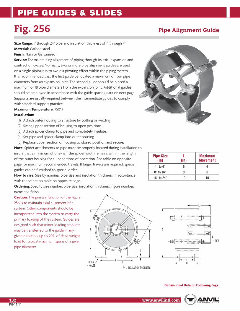
PIPE GUIDES & SLIDES
www.anvilintl.com132
CL
PIPE
W
E
B
J INSULATION THICKNESS
H DIA4 HOLES
D
T
GF
L
C
Fig. 256 Pipe Alignment Guide
Size Range: 1" through 24" pipe and insulation thickness of 1" through 4"Material: Carbon steelFinish: Plain or GalvanizedService: For maintaining alignment of piping through its axial expansion and contraction cycles. Normally, two or more pipe alignment guides are used on a single piping run to avoid a pivoting effect within the piping system. It is recommended that the first guide be located a maximum of four pipe diameters from an expansion joint. The second guide should be placed a maximum of 18 pipe diameters from the expansion joint. Additional guides should be employed in accordance with the guide spacing data on next page. Supports are usually required between the intermediate guides to comply with standard support practice.Maximum Temperature: 750° FInstallation:
(1) Attach outer housing to structure by bolting or welding.(2) Swing upper section of housing to open positions.(3) Attach spider clamp to pipe and completely insulate.(4) Set pipe and spider clamp into outer housing.(5) Replace upper section of housing to closed position and secure.
Note: Spider attachments to pipe must be properly located during installation to insure that a minimum of one-half the spider width remains within the length of the outer housing for all conditions of operation. See table on opposite page for maximum recommended travels. If larger travels are required, special guides can be furnished to special order.How to size: Size by nominal pipe size and insulation thickness in accordance with the selection table on opposite page.Ordering: Specify size number, pipe size, insulation thickness, figure number, name and finish.Caution: The primary function of the Figure256 is to maintain axial alignment of asystem. Other components should beincorporated into the system to carry theprimary loading of the system. Guides aredesigned such that minor loading amountsmay be transferred to the guide in anygiven direction, up to 20% of dead weightload for typical maximum spans of a givenpipe diameter.
Dimensional Data on Following Page.
Pipe Size (in)
L (in)
Maximum Movement
1" to 6" 6 6
8" to 16" 8 8
18" to 24" 10 10
PH-11.11

PIPE GUIDES & SLIDES
Stra
psSp
ring
Hang
ers
Cons
tant
Supp
orts
Vibr
ation
Con
trol
& Sw
ay B
race
Sway
Stru
tAs
sem
bly
Snub
bers
Appl
icatio
nEx
ampl
esSp
ecial
Des
ign
Prod
ucts
Trap
eze
Pipe
Rol
lPi
pe G
uide
s&
Slid
esPi
pe S
hield
s&
Sadd
lesPi
peSu
ppor
tsIn
dex
www.anvilintl.com 133
Tech
nica
lDa
taM
aster
For
mat
3 Pa
rt Sp
ecs.
Fig. 256 Pipe Alignment Guide (cont.)
GUIDE SIZE NUMBER
Pipe Size
Insulation Thickness (in)1 11⁄2 2 21⁄2 3 4
1 A A A B B C
11⁄4 A A A B B C
11⁄2 A A A B B C
2 B B B B C C
21⁄2 B B B B C D
3 B B B C C D
31⁄2 B B B C C D
4 C C C C C D
5 C C C D D E
6 D D D D E E
8 – E E E E F
10 – F F F F F
12 – F F F F G
14 – – G G G G
16 – – G G G G
18 – – – – H H
20 – – – – H H
24 – – – – J J
RECOMMENDED EXPANSION JOINT GUIDE SPACING
Pipe Size* (in)
Maximum Distance (feet) Between Intermediate Guides for Pressure (psig)50 100 150 200 250 300 350 400 500 600
3 38 27 22 20 18 17 15 14 13 12
4 52 37 32 27 25 23 22 19 17 16
6 66 47 40 35 31 28 27 25 23 20
8 85 62 51 45 40 36 35 32 29 27
10 103 75 62 54 50 45 42 40 35 32
12 118 85 70 60 55 50 46 43 40 35
14 120 87 72 62 57 52 48 45 41 37
16 130 95 78 68 61 57 52 49 45 41
18 145 105 87 75 68 62 58 55 50 45
20 155 110 92 90 73 68 62 58 53 49
24 180 128 105 90 83 75 70 65 60 54
* For pipe sizes not shown refer to the Expansion Joint Manufacturers Association Guidelines
GUIDE SIZE SELECTION TABLELocate bare nominal pipe size in appropriate insulation thickness column
and read guide size from “size no.” column to the left.
Guide Size No.
Dimensions (in)
W B C D E F G H T
A 813⁄16 63⁄4 77⁄8 45⁄16 63⁄421⁄2 4
5⁄8 1⁄4B 1013⁄16 83⁄4 97⁄8 55⁄16 73⁄8
C 133⁄4 111⁄4 127⁄16 65⁄8 77⁄8
4 6D 157⁄8 133⁄8 1413⁄16 715⁄16
93⁄4 3⁄4 3⁄8E 18 151⁄2 171⁄16 91⁄8
F 221⁄4 193⁄4 211⁄16 11 141⁄8
51⁄2 8 1 3⁄4G 28 25 261⁄4 139⁄16 157⁄8
H 323⁄8 291⁄4 303⁄4 157⁄8 163⁄8
J 375⁄8 341⁄2 361⁄8 185⁄8 171⁄8
PH-11.11

PIPE GUIDES & SLIDES
www.anvilintl.com134
PTFE Pipe Slide Assemblies Overview
Application Anvil PTFE pipe slide assemblies are designed to support thepipe and provide for lateral and axial movement due to thermal expansion and contraction of the piping system. Assemblies are fabricated using PTFE slide bearings to provide a low coefficient of friction, minimizing frictional stress on the pipe and support structure.Features
• Pre-engineered to save calculation and installation time.• PTFE slide bearing pads are composed of 100% virgin Polytetrafluoroethylene polymer.• Capable of supporting constant loads up to 2000 PSI at 70° F• Coefficient of friction typically ranges between 0.06 and 0.2 depending on bearing surface area, bearing load (sample ranges shown in chart for given pressures at 70˚F). Consult your Anvil representative for further information. The low coefficient of friction for the PTFE slide assemblies permits a smooth, unrestrained movement of the pipe and reduces overturning movements on supporting structures.• PTFE is chemically inert and resists attack by chemicals, humidity and other elements found in harsh environments provided that the steel supports are suitably protected.• Self-lubricating, maintenance-free.• Provides resistance to galvanic corrosion between pipe and support structure.• Maximum temperature: 400° F at PTFE• Allows for up to 4" insulation thickness as standard. Greater than 4" insulation available on special request. Special designed slides and tees available on request.
Selection(1) Determine the support location based on allowable span and loading conditions.(2) Calculate the load for each slide assembly location.(3) Determine the lateral and axial movement of the pipe and the direction of movement, cold to hot.(4) Select pipe slide or tee figure number and attachment configuration, welded or bolted.(5) Select the method of slide plate attachment to support structure, welded or bolted.(6) Designate whether guided or non-guided slide plate is required.(7) Maximum recommended loads shown for pipe slides and structural tees are for vertical loading. Transitional loads for pipe
structural tees are to be determined by customer.Installation
(1) Determine offset of pipe slide-slide plate interface to allow maximum pipe movement in direction of greatest thermal displacement.(2) Attach PTFE slide to pipe by welding or clamping with standard Fig. 212 pipe clamp or Fig. 432 special pipe clamp.(3) Attach slide plates to supporting structure by bolting or welding.(4) Verify setting to insure full bearing between the PTFE slide and slide base surfaces under all pipe movement conditions.
PH-11.11

PIPE GUIDES & SLIDES
Stra
psSp
ring
Hang
ers
Cons
tant
Supp
orts
Vibr
ation
Con
trol
& Sw
ay B
race
Sway
Stru
tAs
sem
bly
Snub
bers
Appl
icatio
nEx
ampl
esSp
ecial
Des
ign
Prod
ucts
Trap
eze
Pipe
Rol
lPi
pe G
uide
s&
Slid
esPi
pe S
hield
s&
Sadd
lesPi
peSu
ppor
tsIn
dex
www.anvilintl.com 135
Tech
nica
lDa
taM
aster
For
mat
3 Pa
rt Sp
ecs.
The maximum load on the pipe slides is based on using a PTFE width of 2" for the slide plate and a 70° F temperature. For a different temperature at the bearing surfaces, multiply the maximum load rating by the following factor.
Temperature °F Factor70 1.00100 0.85200 0.55300 0.40400 0.25
5003.45
10006.89
150010.3
200013.8
Pressure PSI (MPa)
.1
.2
Coef
ficie
nt o
f Fri
ctio
n
COEFFICIENT OF FRICTION VERSUS PRESSURETest Speed: 1"/min. (25mm/min.)
Temperature: 70˚F (21˚C)
PTFE Pipe Slide Assemblies Overview (cont.)
PH-11.11

PIPE GUIDES & SLIDES
www.anvilintl.com136
Fig. 257: Structural Tee Slide Assembly Pipe Slides Assembly, CompleteFig. 257A: Structural Tee
Fig. 436: Fabricated Tee Slide Assembly
Fig. 436A: Fabricated Tee
Size Range: All sizes within maximum load rating.Material: Carbon steel tee, PTFE bonded slide plates and carbon steel base.Finish: Plain, Painted or GalvanizedService: For the support of piping where horizontal movement resultingfrom expansion and contraction takes place and where a low coefficientof friction is desired.Approvals: Complies with Federal Specification A-A-1192A (Type 35),ANSI/MSS SP-69 and MSS SP-58 (Type 35).Maximum Load: As indicated at 70° F see page 135 for rating factor athigher temperatures.Maximum Temperature: 750° FTemperature Range at PTFE: -20° F to 400° FFeatures:
• No lubrication required.• Designed to minimize heat loss.• Allows up to 3" of insulation on Types 1, 2, 4 & 5 and up to 2 1⁄2" of insulation on Types 3 & 6.• Allows up to 10" travel standard• Weld in place design.
Available Options:• Increased travels.• Increased tee heights.• End plates.• Clamps, Fig. 212 or Fig. 432.• Base plate with mounting holes• High temperature option, 1000˚F (Fig. 436) Stainless steel tee slide with an insulated PTFE slide
Ordering: Specify figure number, type, name, finish and any other option desired.
FIG. 257, 436: LOADS (LBS) • DIMENSIONS (IN) • WEIGHTS (LBS)
Figure Number Type
Max Load Welded Slide Bolted Slide
Down Side * Up H ** W BL Weight H ** W BL Hole Locations Bolt Size Weight
Fig. 257
Tee
8,000
– –315⁄16 4 12 7.00 – – – –
1⁄2
–1 43⁄4 4 2 11.93 43⁄4
8 4 21⁄2 x 61⁄215.25
2 2,000 5 8 4 16.10 5 16.103 800 16.95 16.954 – – 43⁄4 6 2 12.47 43⁄4
111⁄2 5 31⁄2 x 1018.36
5 2,000 5 111⁄2 5 18.81 5 19.216 800 19.66 20.06
Fig. 436
Tee
8,000
– –4 4 12 7.00 – – – –
1⁄2
–1 411⁄16 2 15.42 411⁄16
8 4 21⁄2 x 61⁄2
18.742 2,000 415⁄16 8 4 19.59 415⁄16
19.593 800 20.44 20.444 – – 411⁄16 6 2 15.97 411⁄16
111⁄2 31⁄2 x 1021.85
5 2,000 415⁄16 111⁄2 5 22.30 415⁄16 5 22.706 800 23.15 23.55
* Side load is only applicable if appropriate endplates are added to slide or “T” Section** With the Fig. 432 clamp, add the material thickness. The Tees are now being notched for the material thickness when welding on the Fig. 212 See page 141.
Note: In the PH-92 and PH-92R Catalogs: The Fig. 257 & 436 (slide “T” section only) formerly referred to as Fig. 280 & 435 The Fig. 257 & 436 (slide base plate) formerly referred to as Fig. 438 (slide base plate) The acceptability of galvanized coatings at temperatures above 450°F is at the discretion of the end user.
Structural Tees
Fig 257
Fig 436
PTFE Slide
PTFE Slide Plate Base
PTFE Pipe Slide Assembly – "T" Style (Type 1)
PH-11.11

PIPE GUIDES & SLIDES
Stra
psSp
ring
Hang
ers
Cons
tant
Supp
orts
Vibr
ation
Con
trol
& Sw
ay B
race
Sway
Stru
tAs
sem
bly
Snub
bers
Appl
icatio
nEx
ampl
esSp
ecial
Des
ign
Prod
ucts
Trap
eze
Pipe
Rol
lPi
pe G
uide
s&
Slid
esPi
pe S
hield
s&
Sadd
lesPi
peSu
ppor
tsIn
dex
www.anvilintl.com 137
Tech
nica
lDa
taM
aster
For
mat
3 Pa
rt Sp
ecs.
Fig 257, Type 3
Fig 436, Type 31⁄161⁄16
PIPE FIELDWELDED TO TEE
HOLD- DOWNLUGS
H
W
3⁄8
Type 3
Fig 257, Type 4
Fig 436, Type 4
PIPE FIELDWELDED TO TEE
1"
Note: Base Plateis larger than Type 1
1"
W
H
Fig 257, Type 6
Fig 436, Type 6
PIPE FIELDWELDED TO TEE
HOLDDOWNLUGS
Note: Gap is largerthan Type 3
1"1"
W
H
3⁄8
Fig 257, Type 5
Fig 436, Type 5
PIPE FIELDWELDED TO TEE Note: Gap is larger
than Type 2
1"1"
W
H
3⁄8
Fig 257, Type 2
Fig 436, Type 2
PIPE FIELDWELDED TO TEE
W
H1⁄16
3⁄8
1⁄16
Fig. 257 and 436 PTFE Pipe Slide Assemblies
Notes:• Types 1, 2, and 3 provide for longitudinal movement only.• Types 4, 5, and 6 provide for both longitudinal and transverse movement of piping.
Fig 257, Type 1
Fig 436, Type 1
PIPE FIELDWELDED TO TEE
W
H
PTFESLIDE
PLATES
Structural Tee Fabricated Tee
Fig. 257 Fig. 436
Type 1 Type 2
Type 4
Type 5 Type 6
Fig. 257w/Fig 212 Clamps
Fig. 257w/Fig 432 Clamp
Fig. 257w/End Plates
Fig. 257w/Fig 212 Clamps & End Plates
Fig. 436w/Fig 212 Clamps
Fig. 436w/Fig 432 Clamp
Fig. 436w/End Plates
Fig. 436w/Fig 212 Clamps & End Plates
Options (for all types)
12"BL
BASE WITH GUIDESFURNISHED ON
TYPES 2,3,5 & 6 ONLYHOLD-DOWN LUGS
FURNISHED ON TYPE 3 & 6 ONLY
FIG.436 NOTCHED TO REDUCE HEAT LOSS
FIG.257 FEATURES LINE CONTACT WITH PIPE
Side View, All Types
PH-11.11

PIPE GUIDES & SLIDES
www.anvilintl.com138
Fig. 439: Structural "H" Slide Assembly Pipe Slide Assembly, CompleteFig. 439A: Structural "H"
Size Range: 6" through 36"Material: Carbon steel “H” section, PTFE bonded slide plates and carbon steel base.Finish: Plain, Painted or GalvanizedService: A heavy duty slide support where horizontalmovement resulting from expansion and contraction takesplace and where a low coefficient of friction is desired.Approvals: Complies with Federal Specification A-A-1192A (Type 35), ANSI/MSS SP-69 and MSS SP-58 (Type 35).Maximum Load: As indicated at 70° F see page 135 for ratingfactor at higher temperatures.Maximum Temperature: 750° FTemperature Range at PTFE: -20° F to 400° FFeatures:
• No lubrication required.• Allows up to 4" of insulation.• Allows up to 10” travel standard.• Weld in place design.
Available Options:• Increased travels.• Increased “H” Section heights.• Clamps, Fig. 212 or Fig. 432.• Base plate with mounting holes. The bolt spacing for the bolted base plates is equal to the “W” dimention minus 1 1⁄2" and the “BL” dimention minus 1 1⁄2" for all pipe sizes and the hole diameter is 9⁄16" for all sizes.
Ordering: Specify figure number, type, name, finish and anyother option desired.Notes: Types 1, 2, and 3 provide for longitudinal movement only.Types 4 and 5 provide for both longitudinal and transversemovement of piping.
PTFE Pipe Slide Assembly – "H" Type
Structural "H"
PTFE Slide Plate Base
Mounting Plate
PTFE Slides
FIG. 439: LOADS (LBS) • DIMENSIONS (IN)
Pipe Size
B D * Max LoadType Type
DownSide Type
2, 3, 5
Up Type 31 & 4 2 & 5 3 1 & 4 2 & 5 3
65 51⁄4 55⁄16
73⁄4 8 812,000 3,000 1,200
8 83⁄4 9 910
51⁄8 53⁄8 57⁄16
95⁄8 97⁄8 915⁄16
16,000 4,000 1,600
12 103⁄4 11 111⁄16
14 107⁄8 111⁄8 113⁄16
16 121⁄8 123⁄8 127⁄16
18 125⁄8 127⁄8 1215⁄16
20 133⁄4 14 141⁄16
24 51⁄4 51⁄2 59⁄16 155⁄8 157⁄8 1515⁄16
24,000 6,000 2,40030 61⁄4 65⁄8 611⁄16 195⁄8 197⁄8 201⁄16
36 67⁄16 613⁄16 63⁄4 23 231⁄4 237⁄16
* With clamps; add material thickness of a Fig. 212 for bolted bases add 5⁄16" to height “H” dimension.** With the Figure 432 special clamp, add the material thickness of Figure 432. See page 140.
D
B
FIELD WELDPIPE TO FIG 439
PTFE SLIDE PLATES
Note: In the PH-92 and PH-92R Catalogs: The Fig. 439 (slide “H” section only) formerly referred to as Fig. 437. The Fig. 439 (slide base plate) formerly referred to as Fig. 438(slide base plate).
The acceptability of galvanized coatings at temperatures above 450°F is at the discretion of the end user.
PH-11.11

PIPE GUIDES & SLIDES
Stra
psSp
ring
Hang
ers
Cons
tant
Supp
orts
Vibr
ation
Con
trol
& Sw
ay B
race
Sway
Stru
tAs
sem
bly
Snub
bers
Appl
icatio
nEx
ampl
esSp
ecial
Des
ign
Prod
ucts
Trap
eze
Pipe
Rol
lPi
pe G
uide
s&
Slid
esPi
pe S
hield
s&
Sadd
lesPi
peSu
ppor
tsIn
dex
www.anvilintl.com 139
Tech
nica
lDa
taM
aster
For
mat
3 Pa
rt Sp
ecs.
WELDED: DIMENSIONS (IN)
Pipe Size
W BLType Type
1 2 & 3 4 5 1 & 4 2, 3, & 56
51/2 10 71/2 10
2
6
810
8 121/2 101/2 121/21214
10 141/2 121/2 141⁄21618
12 17 141/2 172024 14 19 161/2 19
330 16 21 181/4 2136 18 23 201/4 23
Fig. 439 Structural “H” Slide Assembly, Complete
BOLTED: DIMENSIONS (IN)
Pipe Size WType 1 to 5
BLType 1 to 5
Hole SpacingC G
610
6
81⁄2
41/2
810
121/2 111214
141/2 131618
17 151⁄22024 19 171⁄230 21 191⁄236 23 211/2
WELDED SCHEMATICS
W BL
12
12
W BL
1/16
12
BLW
1
W BL
12
1
Type 1
Types2 & 3
Type 4
Type 5
BOLTED SCHEMATICS
WC
BLG
12
W
12
BLGC
1/16
WC
12
BLG
1
WC
12
BLG
1
Type 1
Types2 & 3
Type 4
Type 5
Notes:• Types 1, 2, and 3 provide for longitudinal movement only.• Types 4 and 5 provide for both longitudinal and transverse movement of piping.
"H" Section Only
Options(for all types)
Fig.439w/Fig 212 Clamps
Fig. 439w/Fig 432 Clamp
PH-11.11

PIPE GUIDES & SLIDES
www.anvilintl.com140
Fig. 432 Special Clamp
Size Range: 2" through 24"Material: Carbon steelFinish: Plain or GalvanizedMaximum Temperature: Plain 750° F, Galvanized 450° F for carbon steel pipe onlyService: Used with and where pipe slides cannot be welded directly to pipe or copper tube. When used with fiberglass,plastic, or aluminum pipe, a thin protective liner should beinserted between the pipe and the clamp. Clamp is designedfor use with Figure 257 and Figures 436 and 439 slides and tees.Ordering: Specify figure number, pipe size, name and finish.
FIG. 432: WEIGHT (LBS) • DIMENSIONS (IN)
Pipe Size L M N P Q RStock Size Weight
2
6
5 4
1⁄4 41⁄2 1/8 x 6
221⁄2 51⁄2 41⁄2 33 6 5 3
31⁄2 61⁄2 51⁄2 44 7 6 45 8 7 56
8
95⁄8 81⁄2 3⁄8
63/16 x 8
128 115⁄8 101⁄2 1510 133⁄4 125⁄8
1⁄2
1812 153⁄4 145⁄8 2114
12
177⁄8 161⁄2
1/4 x 12
4116 197⁄8 181⁄2
8
4618 217⁄8 201⁄2 5220 237⁄8 221⁄2 5⁄8
5724 281⁄8 267⁄8 67
N Q
ML
P
R
Fig. 257w/Fig 432 Clamp
Fig. 436w/Fig 432 Clamp
Fig. 439w/Fig 432 Clamp
PH-11.11

PIPE GUIDES & SLIDES
Stra
psSp
ring
Hang
ers
Cons
tant
Supp
orts
Vibr
ation
Con
trol
& Sw
ay B
race
Sway
Stru
tAs
sem
bly
Snub
bers
Appl
icatio
nEx
ampl
esSp
ecial
Des
ign
Prod
ucts
Trap
eze
Pipe
Rol
lPi
pe G
uide
s&
Slid
esPi
pe S
hield
s&
Sadd
lesPi
peSu
ppor
tsIn
dex
www.anvilintl.com 141
Tech
nica
lDa
taM
aster
For
mat
3 Pa
rt Sp
ecs.
Fig. 212 Medium Pipe Clamp
Size Range: 2" through 30"Material: Carbon steelFinish: Plain or GalvanizedMaximum Temperature: Plain 750° F, Galvanized 450° FService: Pipe clamp for figure numbers 257, 436, and 439 slides and tees.Ordering: Specify pipe size, figure number, name and finish.Note: Two clamps are required. “T” section 257/436 or “H” section439 are notched to accommodate clamps and to eliminate theincrease in height of the slide assembly.
FIG. 212: WEIGHT (LBS) • DIMENSIONS (IN)Pipe Size B C D E H F G Width Weight
2 21⁄8 1⁄2 23⁄4 21⁄8 23⁄4
1⁄2 1
2.2
21⁄2 25⁄8
5⁄8
31⁄4 25⁄8 31⁄4 2.4
3 27⁄8 31⁄2 27⁄8 31⁄2 2.8
31⁄2 33⁄16 313⁄16 33⁄16 313⁄16 3.0
4 31⁄2 41⁄4 31⁄2 41⁄4 4.6
5 43⁄163⁄4
415⁄16 43⁄16 415⁄16 5⁄8 11/4 5.2
6 47⁄8 53⁄4 47⁄8 53⁄43⁄4 11/2
10.8
8 6 11⁄4 67⁄8 6 67⁄8 13.0
10 77⁄161
89⁄16 77⁄16 89⁄16
7⁄8
227.2
12 87⁄16 99⁄16 87⁄16 99⁄16 30.4
14 91⁄411⁄8
105⁄8 91⁄4 105⁄8
21/2
41.0
16 101⁄4 115⁄8 101⁄4 115⁄8 44.6
18 115⁄8 11⁄4 13 115⁄8 13 1 63.2
20 123⁄4 13⁄8 141⁄8 123⁄4 141⁄8 11⁄8 71.6
24 151⁄4 15⁄8 167⁄8 151⁄4 167⁄8 11⁄4 3 106.2
30 19 2 211⁄8 19 211⁄8 13⁄4 4 227.8
PIPE GUIDES & SLIDES
Fig.439w/Fig 212 Clamps
Fig. 257w/Fig 212 Clamps
Fig. 436w/Fig 212 ClampsDH
B E
F
C
CL
G
PH-11.11

SPRING HANGERS
www.anvilintl.com142
Fig. 82, Fig. B-268, Fig. 98, Triple Spring, and Quadruple SpringFig. C-82, Fig. C-268, Fig. C-98, Triple-CR, and Quadruple-CR Spring
(Corrosion Resistant)
Design features:• Precompression. Precompressing the spring into the hanger casing provides the fol-
lowing advantages:(1) Saves up to 50% in headroom by reducing the length of the
hanger.(2) Reduces the installed height of the overall hanger assembly.(3) Prevents the spring supporting force from exceeding the nor-
mal safe limits of variations.(4) Saves valuable erection time because spring is
precompressed close to 1⁄2" of the working range.• Calibration: all Anvil Variable Spring Hangers and supports are
calibrated for accurate loading conditions.• Load indicator is clearly seen in the slot, simplifying reading
of the scale plate. Load is read from bottom of indicator.• Cold set at the factory upon request.• Spring and casing are fabricated of steel and are rugged and
compact.• Piston cap serves as a centering device or guide maintaining spring
alignment.• Casing protects the spring from damage and weather conditions.Standard Finish: Painted with semi-gloss primer.Corrosion Resistant: Anvil offers corrosion-resistant and weather- resistant Variable Spring Hangers to fill vital needs in the chemical and refinery industries as well as in modern outdoor power plant construction. For protection against severe weather condi-tions or moderate corrosive conditions, the parts of the hanger are galvanized per ASTM A-153, except the spring which has a protective coating and the load column for Type F which is electro-galvanized.Advantages of a Protective Coating:• Protects from a wide range of corrosives.• Does not affect the flex life of the spring.• Recommended for ambient temperatures up to 200° FTravel stop: The functional design of the pre-compressed variable spring hanger permits the incorporation of a two-piece travel stop that locks the hanger spring against upward or downward movement for temporary conditions of underload or overload. The complete travel stop, the up travel stop only for cold set purposes or the down travel stop only which may be employed during erection, hydrostatic test (Anvil permits a hydrostatic test load of 2 times the normal operating load for the spring hanger) or chemical cleanout will be furnished only when specified. The travel stopis painted red and isinstalled at the factorywith a caution tag attached calling attentionthat the device must beremoved before the pipeline is put in service.Permanently attached travelstops available upon request.
Approvals: WW-H-171E (Types 51, 56 and 57), ANSI/MSS SP-69 and MSS SP-58 (Types 51, 52 and 53).Specifications: Anvil Variable Spring Hangers are welded in strict accordance with ASME Section IX.Size Range: The Anvil Variable Spring Hanger in five series and seven types is offered in twenty-three sizes (Fig. B-268 only is offered in twenty-five sizes). The hanger can be furnished to take loads 10 lbs. to 50,000 lbs.Ordering:(1) Size(2) Type(3) Figure number(4) Product name(5) Desired supporting force in operating position(6) Calculated amount and direction of pipe movement from installed
to operating position.(7) Customer’s identification number (if any)(8) When ordering Type F spring specify if roller or guided load column is to be furnished.(9) When ordering Type G, specify total load and load per spring plus
center to center rod dimensions.(10) If required, specify with travel stop(11) When ordering corrosion resistant, specify C-268, C-82, C-98,
Triple-CR, or Quadruple-CR “ completely galvanized except coated spring coil”.
Note: To help alleviate the problem of lifting large size spring hangers into position for installation, this product is available with lifting lugs (if required) on sizes weighing one hundred pounds or more.
LIFTINGLUGSHole
CAUTION
METALSTRAPS
UP TRAVELSTOP
DOWN TRAVELSTOP
INDICATOR(Load is read from
bottom of indicator)
CAUTIONTAG
Figure 82
Figure B-268
Figure 98
PH-11.11

SPRING HANGERS
Stra
psSp
ring
Hang
ers
Cons
tant
Supp
orts
Vibr
ation
Con
trol
& Sw
ay B
race
Sway
Stru
tAs
sem
bly
Snub
bers
Appl
icatio
nEx
ampl
esSp
ecial
Des
ign
Prod
ucts
Trap
eze
Pipe
Rol
lPi
pe G
uide
s&
Slid
esPi
pe S
hield
s&
Sadd
lesPi
peSu
ppor
tsIn
dex
www.anvilintl.com 143
Tech
nica
lDa
taM
aster
For
mat
3 Pa
rt Sp
ecs.
Fig. 82, Fig. B-268, Fig. 98, Triple Spring, and Quadruple Spring (cont.)Fig. C-82, Fig. C-268, Fig. C-98, Triple-CR, and Quadruple-CR Spring
(Corrosion Resistant)
How to Determine Type: The type of variable spring hanger to be used depends upon the physical characteristics required by the suspension problem (e.g., amount of head room, whether pipe is to be supported above or below the spring, etc.).
Consideration should be given to the seven standard types offered (see illustration below). Special variable spring hangers can be fabri-cated for unusual conditions.
Recommended Service: Pipe hangers located at points that are subject to vertical thermal movement and for which a constant support hanger is not required (see “recommended service” for constant support hanger, page 161). Type D & E spring hangers may accommodate less than 4° of rod swing depending on size, figure number, and application.Installation: Securely attach hanger to the building. Attach lower hanger rod and turn the load coupling until the load indicator is positioned at the desired setting indicated on the load scale plate.
Adjustment of Hanger: Once installed in the line; the hanger should be adjusted until the load indicator moves to the white button marked “C” (cold position). On inspection of the system, after a reasonable period of operation, the load indicator should be at the red button marked “H” (hot position). If it is not, the hanger should be readjusted to the hot position. No other adjustment is necessary.How to Determine Series: Complete sizing information is given on the hanger selection chart on pages 144 and 145. The sizing information is applicable to hangers of all series. As noted on the hanger selection charts that the total spring deflection in the casing leaves a reserve (overtravel) above and below the recommended working load range.
Spring Hanger Types – Typical Applications
Type A Type B Type C Type D
Type E Type F Type G
PH-11.11

SPRING HANGERS
www.anvilintl.com144
How to use hanger selection table: In order to choose a proper size hanger, it is necessary to know the actual load which the spring is to support and the amount and direction of the pipe line movement from the cold to the hot position. Find the actual load of the pipe in the load table. As it is desirable to support the actual weight of the pipe when the line is hot, the actual load is the hot load. To determine the cold load, read the spring scale, up or down, for the amount of expected movement.
The chart must be read opposite from the direction of the pipe’s movement. The load arrived at is the cold load. If the cold load falls outside of the working load range of the hanger selected, relocate the actual or hot load in the adjacent column and find the cold load. When the hot and cold loads are both within the working range of a hanger, the size number of that hanger will be found at the top of the column.
Spring Hanger Size and Series Selection
LOAD TABLE (LBS) FOR SELECTION OF HANGER SIZE (sizes 10 through 22 on next page)
Working Range (in) unshaded Shaded Rows Show Overtravel
Hanger size
B-268 Only Fig. 82, Fig. B-268, Fig. 98, Triple & Quadruple SpringFigure No.
Quad. Triple 98 B-268 82 000 00 0 1 2 3 4 5 6 7 8 9
2 11⁄2 1 1⁄2 1⁄4
7 19 43 63 81 105 141 189 252 336 450 600
7 20 44 66 84 109 147 197 263 350 469 625
8 22 46 68 88 114 153 206 273 364 488 650
9 24 48 71 91 118 159 213 284 378 506 675
0 0 0 0 0 10 26 50 74 95 123 165 221 294 392 525 700
11 28 52 76 98 127 170 228 305 406 544 725
12 30 54 79 101 131 176 236 315 420 563 750
12 31 56 81 105 136 182 244 326 434 581 775
2 11⁄2 1 1⁄2 1⁄4 14 34 58 84 108 140 188 252 336 448 600 800
14 35 59 87 111 144 194 260 347 462 619 825
15 38 61 89 115 149 200 268 357 476 638 850
16 40 63 92 118 153 206 276 368 490 656 875
4 3 2 1 1⁄2 17 41 65 95 122 158 212 284 378 504 675 900
18 43 67 97 125 162 217 291 389 518 694 925
19 45 69 100 128 166 223 299 399 532 713 950
20 47 71 102 132 171 229 307 410 546 731 975
6 41⁄2 3 11⁄2 3⁄4 21 49 73 105 135 175 235 315 420 560 750 1,000
21 50 74 108 138 179 241 323 431 574 769 1,025
22 53 76 110 142 184 247 331 441 588 788 1,050
23 55 78 113 145 188 253 339 452 602 806 1,075
8 6 4 2 1 24 56 80 116 149 193 258 347 462 616 825 1,100
25 58 82 118 152 197 264 354 473 630 844 1,125
26 60 84 121 155 201 270 362 483 644 863 1,150
27 62 86 123 159 206 276 370 494 658 881 1,175
10 71⁄2 5 21⁄2 11⁄4 28 64 88 126 162 210 282 378 504 672 900 1,200
2 11⁄2 1 1⁄2 1⁄4
28 66 89 129 165 214 288 386 515 686 919 1,225
29 68 91 131 169 219 294 394 525 700 938 1,250
30 70 93 134 172 223 300 402 536 714 956 1,275
31 72 95 137 176 228 306 410 546 728 975 1,300
Spring Rate (lbs/In)82 – – 30 42 54 70 94 126 168 224 300 400
B-268 7 15 15 21 27 35 47 63 84 112 150 200
98 – – 7 10 13 17 23 31 42 56 75 100
Triple – – 5 7 9 12 16 21 28 37 50 67
Quadruple – – 4 5 7 9 12 16 21 28 38 50
Note: General rule for series selection use Fig. 82 for up to 1⁄2" of movement up to 1" use Fig. B-268, up to 2" use Fig. 98, up to 3" use a Triple, up to 4" use a Quadruple. Double check to assure desired variability is achieved.
PH-11.11

SPRING HANGERS
Stra
psSp
ring
Hang
ers
Cons
tant
Supp
orts
Vibr
ation
Con
trol
& Sw
ay B
race
Sway
Stru
tAs
sem
bly
Snub
bers
Appl
icatio
nEx
ampl
esSp
ecial
Des
ign
Prod
ucts
Trap
eze
Pipe
Rol
lPi
pe G
uide
s&
Slid
esPi
pe S
hield
s&
Sadd
lesPi
peSu
ppor
tsIn
dex
www.anvilintl.com 145
Tech
nica
lDa
taM
aster
For
mat
3 Pa
rt Sp
ecs.
LOAD TABLE (LBS) FOR SELECTION OF HANGER SIZE (Continued from previous page)
Hanger size Working Range (in) unshaded Shaded Rows Show Overtravel
Fig. 82, Fig. B-268, Fig. 98, Triple & Quadruple Spring Figure No.
10 11 12 13 14 15 16 17 18 19 20 21 22 82 B-268 98 Triple Quad.
780 1,020 1,350 1,800 2,400 3,240 4,500 6,000 7,990 10,610 14,100 18,750 25,005
1⁄4 1⁄2 1 11⁄2 2813 1,063 1,406 1,875 2,500 3,375 4,688 6,250 8,322 11,053 14,588 19,531 26,047
845 1,105 1,463 1,950 2,600 3,510 4,875 6,500 8,655 11,495 15,275 20,313 27,089
878 1,148 1,519 2,025 2,700 3,645 5,063 6,750 8,987 11,938 15,863 21,094 28,131
910 1,190 1,575 2,100 2,800 3,780 5,250 7,000 9,320 12,380 16,450 21,875 29,173 0 0 0 0 0943 1,233 1,631 2,175 2,900 3,915 5,438 7,250 9,652 12,823 17,038 22,656 30,215
975 1,275 1,688 2,250 3,000 4,050 5,625 7,500 9,985 13,265 17,625 23,438 31,256
1,008 1,318 1,744 2,325 3,100 4,185 5,813 7,750 10,317 13,708 18,213 24,219 32,298
1,040 1,360 1,800 2,400 3,200 4,320 6,000 8,000 10,650 14,150 18,800 25,000 33,340 1⁄4 1⁄2 1 11⁄2 21,073 1,403 1,856 2,475 3,300 4,455 6,188 8,250 10,982 14,592 19,388 25,781 34,382
1,105 1,445 1,913 2,550 3,400 4,590 6,375 8,500 11,315 15,035 19,975 26,563 35,424
1,138 1,488 1,969 2,625 3,500 4,725 6,563 8,750 11,647 15,477 20,563 27,344 36,466
1,170 1,530 2,025 2,700 3,600 4,860 6,750 9,000 11,980 15,920 21,150 28,125 37,508 1⁄2 1 2 3 41,203 1,573 2,081 2,775 3,700 4,995 6,938 9,250 12,312 16,362 21,738 28,906 38,549
1,235 1,615 2,138 2,850 3,800 5,130 7,125 9,500 12,645 16,805 22,325 29,688 39,591
1,268 1,658 2,194 2,925 3,900 5,265 7,313 9,750 12,977 17,247 22,913 30,469 40,633
1,300 1,700 2,250 3,000 4,000 5,400 7,500 10,000 13,310 17,690 23,500 31,250 41,675 3⁄4 11⁄2 3 41⁄2 61,333 1,743 2,306 3,075 4,100 5,535 7,688 10,250 13,642 18,132 24,088 32,031 42,717
1,365 1,785 2,363 3,150 4,200 5,670 7,875 10,500 13,975 18,575 24,675 32,813 43,759
1,398 1,828 2,419 3,225 4,300 5,805 8,063 10,750 14,307 19,017 25,263 33,594 44,801
1,430 1,870 2,475 3,300 4,400 5,940 8,250 11,000 14,640 19,460 25,850 34,375 45,843 1 2 4 6 81,463 1,913 2,531 3,375 4,500 6,075 8,438 11,250 14,972 19,902 26,438 35,156 46,885
1,495 1,955 2,588 3,450 4,600 6,210 8,625 11,500 15,305 20,345 27,025 35,938 47,926
1,528 1,998 2,644 3,525 4,700 6,345 8,813 11,750 15,637 20,787 27,613 36,719 48,968
1,560 2,040 2,700 3,600 4,800 6,480 9,000 12,000 15,970 21,230 28,200 37,500 50,010 11⁄4 21⁄2 5 71⁄2 101,593 2,083 2,756 3,675 4,900 6,615 9,188 12,250 16,302 21,672 28,788 38,281 51,052
1⁄4 1⁄2 1 11⁄2 21,625 2,125 2,813 3,750 5,000 6,750 9,375 12,500 16,635 22,115 29,375 39,063 52,094
1,658 2,168 2,869 3,825 5,100 6,885 9,563 12,750 16,967 22,557 29,963 39,844 53,136
1,690 2,210 2,925 3,900 5,200 7,020 9,750 13,000 17,300 23,000 30,550 40,625 54,178
Spring Rate (lbs/In)520 680 900 1,200 1,600 2,160 3,000 4,000 5,320 7,080 9,400 12,500 16,670 82260 340 450 600 800 1,080 1,500 2,000 2,660 3,540 4,700 6,250 8,335 B-268130 170 225 300 400 540 750 1,000 1,330 1,770 2,350 3,125 4,167 9887 113 150 200 267 360 500 667 887 1,180 1,567 2,083 2,778 Triple65 85 113 150 200 270 375 500 665 885 1,175 1,563 2,084 Quadruple
Note: General rule for series selection use Fig. 82 for up to 1⁄2" of movement up to 1" use Fig. B-268, up to 2" use Fig. 98, up to 3" use a Triple, up to 4" use a Quadruple. Double check to assure desired variability is achieved.
How to use hanger selection table (cont.): Should it be impossible to select a hanger in a particular series such that both loads occur within the working range, consideration should be given to a variable spring hanger with a wider working range or a constant support hanger. The cold load is calculated by adding (for up movement) or subtracting (for down movement) the product of spring rate times movement to or from the hot load.
Cold load = (hot load) ± (movement) x (spring rate) A key criteria in selecting the size and series of a variable spring is a factor known as variability. This is a measurement of the percentage change in supporting force between the hot and cold positions of a spring and is calculated from the formula: Variability = (Movement) x (Spring Rate) / (Hot Load) If an allowable variability is not specified, good practice would be to use 25% as recommended by MSS-SP-58.
Spring Hanger Size and Series Selection
PH-11.11
SPRING HANGERS
www.anvilintl.com146
Variable Spring Check List for Requesting a Quote or Ordering
Finish: Standard Primer: __________ Galvanized: __________ Special Coating: _______________
Quantity: _______________
Figure No.: Options a re: ❏ 82, ❏ B-268, ❏ 98, ❏ Triple, ❏ Quadruple or: ❏ C-82, ❏ C-268, ❏ C-98, ❏ Triple-CR, ❏ Quadruple-CR
Size: Options are: #0 through #22 (B-268 / C-268 also available in #00 and #000) ______________________
Type: Options are: A through G* ___________________________
Hot (Operating or Design) Load (lbs): _______________ (optional)**
Cold/Installed (Factory Set) Load (lbs): _______________ (optional)**
Vertical Movement: _______________ + (up) or – (down) (optional)**
Mark Number: _______________ (If Required)
Travel Stops: Yes: _______________ No: _______________ If travel stops are ordered and hot & cold loads are not provided, then the spring will be set to mid range load.
Lifting Lugs: Yes: _________ No: __________ Available on sizes weighing 100 lbs or more.
Notes: * Type G Springs must also include the C-to-C dimension & the load per spring. ** Anvil will determine the appropriate Figure Number and will calculate the Cold Load when only the
Hot Load and movement are specified.
Anvil International
Precision Park
160 Frenchtown Rd.
North Kingstown, RI 02852
For technical information regarding
Variable Springs Call or Fax:
Fax Number: (401) 886-3056
Phone Number: (401) 886-3025
Page ___ of ____
PH-11.11

SPRING HANGERS
Stra
psSp
ring
Hang
ers
Cons
tant
Supp
orts
Vibr
ation
Con
trol
& Sw
ay B
race
Sway
Stru
tAs
sem
bly
Snub
bers
Appl
icatio
nEx
ampl
esSp
ecial
Des
ign
Prod
ucts
Trap
eze
Pipe
Rol
lPi
pe G
uide
s&
Slid
esPi
pe S
hield
s&
Sadd
lesPi
peSu
ppor
tsIn
dex
www.anvilintl.com 147
Tech
nica
lDa
taM
aster
For
mat
3 Pa
rt Sp
ecs.
Fig. B-268, C-268 Spring Hangers (Type A)
Type A is the basic unit of Fig. B-268 Anvil Variable Spring Hanger. It is designed for attachment to its supporting member by screwing a rod into a tapped hole in the top cap of the hanger the full depth of the top cap (“G” dimension). The upper jam nut should then be locked, securing the hanger. Adjustment of the hanger load is accomplished by turning the coupling on the lower hanger rod until the hanger picks up the load and the load indicator points to the desired position.
FIG. B-268, FIG. C-268 TYPE A: WEIGHT (LBS) • DIMENSIONS (IN)
Hanger Size Weight Rod Size
A
R.H. Thread Length
Casing Length
B
Casing Diam
C
Flange Diam
D
Rod Take Out
E
Min. Thread Engagement
F
Thread Depth
GZ
000 5 1⁄2 555⁄8
4 51⁄851⁄16 15⁄16 7⁄16
13⁄16
00 6 79⁄16 73⁄8 13⁄16
0 81⁄2 5
611⁄16
4 51⁄861⁄16
15⁄16 7⁄16
3⁄41 8 79⁄16 615⁄16
2 9 85⁄16 715⁄16 13 14
1⁄2 5715⁄16
59⁄16 615⁄16
79⁄16
15⁄16 7⁄16
14 15 715⁄16
715⁄1613⁄8
5 16 85⁄8 11⁄16
6 265⁄8 5
813⁄16
65⁄8 83⁄8713⁄16
15⁄16 5⁄8
9⁄16
7 2910 91⁄16 5⁄8
8 319 65
3⁄4 6107⁄16
85⁄8 103⁄4815⁄16
11⁄4 1
3⁄410 71 121⁄8 113⁄8 11⁄211 65 107⁄16 97⁄8 111⁄16
12 711
6 107⁄16
85⁄8 103⁄491⁄2
11⁄41
11⁄16
13 897
131⁄8 113⁄8 1⁄214 93 11⁄4 131⁄4 113⁄8 11⁄4 3⁄815 111 11⁄4 7 131⁄4
85⁄8103⁄4 113⁄8 11⁄4 11⁄4 3⁄8
16 133 11⁄28
161⁄16113⁄8
1413⁄16115⁄16
13⁄8 21⁄16
17 162 13⁄4 181⁄8 163⁄4 13⁄8 115⁄16
18 330 29
181⁄4123⁄4 157⁄8
1623⁄4 21⁄4
29⁄16
19 376 21⁄4 201⁄2 183⁄8211⁄16
20 480 21⁄2 10 233⁄4 215⁄821 556 23⁄4 10 275⁄16
123⁄4 167⁄8237⁄8
35⁄823⁄4 311⁄16
22 705 3 11 333⁄8 293⁄4 3 33⁄4
MARKNO.SIZE TYPE
FIG. B-268SPG.RATE LB./IN.
1/4113/41/21/40
2 1/2
1/213/41
21/42
DEFL. (IN.) LOAD (LB.)
C
B
D
F
E
G
ROD SIZE "A"
MIN.=ZMAX.=Z+3 1/2"
ROD SIZE "A"ROD NOT FURNISHEDLENGTH OF R.H. TH'DSEE TABLE BELOW
LOAD INDICATOR
LOAD SCALE &NAME PLATE
PH-11.11

SPRING HANGERS
www.anvilintl.com148
Type B is furnished with a single lug for attachment to the building structure. The lug permits use of a clevis, welded beam attachment or a pair of angles for attachment where headroom is limited.
Type C is furnished with two lugs for attachment to the building structure. These two lugs permit the use of an eye rod, Fig. 55L or a single plate for attachment where headroom is limited.
Fig. B-268, C-268 Spring Hangers (Type B & Type C)
FIG. B-268, FIG. C-268 TYPE B, C: WEIGHT (LBS) • DIMENSIONS (IN)
Hanger Size
Weight (lbs)
Rod Size
A
R.H. Thread Length
Lug Hole Size
Casing Length
B
Casing Diam
C
Flange Diam
D
Min. Thd Engagement
F
Height of Pin
H
Rod Take Out J
RClevis
Opening S
Thickness T Z
000 5 1⁄2 5 11⁄1655⁄8
4 51⁄8 15⁄16 11⁄27
11⁄4 7⁄8 1⁄413⁄16
00 6 79⁄16 91⁄2 13⁄16
0 81⁄2 5 11⁄16
611⁄16
4 51⁄8 15⁄16 11⁄28
11⁄4 7⁄8 1⁄43⁄4
1 9 79⁄16 87⁄82 10 85⁄16 97⁄8 13 14
1⁄2 5 11⁄16715⁄16
59⁄16 615⁄16 15⁄16 11⁄291⁄2
11⁄4 7⁄8 1⁄41
4 1697⁄8
13⁄85 17 85⁄8 11⁄16
6 275⁄8 5 13⁄16
813⁄16
65⁄8 83⁄8 15⁄16 11⁄2915⁄16
11⁄4 11⁄16 1⁄4
9⁄16
7 3010 113⁄16 5⁄8
8 329 66
3⁄4 6 15⁄16
107⁄16
85⁄8 103⁄4 11⁄4 11⁄2117⁄16
11⁄4 11⁄4 3⁄8
3⁄410 72 121⁄8 137⁄8 11⁄211 66 107⁄16 123⁄8 111⁄16
12 711
611⁄4
107⁄16
85⁄8 103⁄4 11⁄42
121⁄211⁄2 15⁄8 1⁄2
11⁄16
13 897
131⁄8 143⁄8 1⁄214 94 11⁄4 11⁄2 131⁄4 3 153⁄8 2 2 5⁄8 3⁄815 114 11⁄4 7 11⁄2 131⁄4
85⁄8103⁄4
115⁄16 3153⁄8 2 2 5⁄8 3⁄8
16 138 11⁄28
13⁄4 161⁄16113⁄8
193⁄1621⁄2
23⁄8 3⁄421⁄16
17 168 13⁄4 2 181⁄8 211⁄8 25⁄8 115⁄16
18 331 29
23⁄8 181⁄4123⁄4 157⁄8 23⁄4
4 221⁄83
27⁄8 3⁄429⁄16
19 378 21⁄4 25⁄8 201⁄241⁄2
25 31⁄8211⁄16
20 486 21⁄2 10 27⁄8 233⁄4 281⁄4 4 33⁄8 121 568 23⁄4 10 31⁄8 275⁄16
123⁄4 167⁄8 35⁄841⁄2 311⁄8
435⁄8
1311⁄16
22 714 3 11 33⁄8 333⁄8 5 373⁄4 37⁄8 33⁄4
MARKNO.SIZE TYPE
FIG. B-268SPG.RATE LB./IN.
1/4113/41/21/40
2 1/2
1/213/41
21/42
DEFL. (IN.) LOAD (LB.)
D
T
F
C
J
H
R
B
LOAD SCALE& NAME PLATE
ROD SIZE "A"ROD NOT FURNISHEDLENGTH OF R.H. TH'D.SEE TABLE BELOW
MIN.=ZMAX.=Z+3 1/2"
LOADINDICATOR
MARKNO.SIZE TYPE
FIG. B-268SPG.RATE LB./IN.
1/4113/41/21/40
2 1/2
1/213/41
21/42
DEFL. (IN.) LOAD (LB.)
DT
S
H
R
B
LOAD SCALE &NAME PLATE
MIN.=ZMAX.=Z+3 1/2"
LOADINDICATOR
ROD SIZE "A"ROD NOT FURNISHEDLENGTH OF R.H. TH'D.SEE TABLE BELOW
F
J
C
Fig. B-268 Type B Fig. B-268 Type C
PH-11.11

SPRING HANGERS
Stra
psSp
ring
Hang
ers
Cons
tant
Supp
orts
Vibr
ation
Con
trol
& Sw
ay B
race
Sway
Stru
tAs
sem
bly
Snub
bers
Appl
icatio
nEx
ampl
esSp
ecial
Des
ign
Prod
ucts
Trap
eze
Pipe
Rol
lPi
pe G
uide
s&
Slid
esPi
pe S
hield
s&
Sadd
lesPi
peSu
ppor
tsIn
dex
www.anvilintl.com 149
Tech
nica
lDa
taM
aster
For
mat
3 Pa
rt Sp
ecs.
Fig. B-268, C-268 Spring Hangers (Type D & Type E)
FIG. B-268, FIG. C-268 TYPE D, E: WEIGHT (LBS) • DIMENSIONS (IN)
Hanger Size
Weight (lbs)
Rod Size
A
R.H. Thd Length
Casing Length
B
Casing Diam
C
Flange Diam
D
Min Thread Engagement
F
Allowance for Nuts
K
Height of Spacer
M
Rod Length
Y
Rod Take-out
Q
000 5 1⁄2 555⁄8
4 51⁄8 13⁄16 11⁄4 31⁄810
600 6 79⁄16 113⁄40 6
1⁄2 5611⁄16
4 51⁄8 15⁄16 11⁄4 31⁄8111⁄16
61 7 79⁄16 1115⁄16
2 8 85⁄16 1211⁄16
3 111⁄2 5
715⁄1659⁄16 615⁄16 15⁄16 11⁄4 31⁄8
1111⁄16
64 12 125⁄16
5 14 85⁄8 136 22
5⁄8 5813⁄16
65⁄8 83⁄8 15⁄16 11⁄2 3135⁄16
67 2510
141⁄48 26 143⁄49 51
3⁄4 6107⁄16
85⁄8 103⁄4 11⁄4 13⁄4 3155⁄8
610 58 121⁄8 167⁄811 51 107⁄16 1411⁄16
12 561
6 107⁄16
85⁄8 103⁄4 11⁄421⁄4
31513⁄16
613 737 131⁄8
183⁄814 77 11⁄4 3 191⁄415 88 11⁄4 7 131⁄8
85⁄8103⁄4 11⁄4 3
3193⁄4
616 107 11⁄28
1515⁄16113⁄8 115⁄16
31⁄2 229⁄16
17 133 13⁄4 18 4 251⁄818 262 2
9181⁄4
123⁄4 157⁄8 23⁄449⁄16
32511⁄16
619 300 21⁄4 201⁄2 5 283⁄820 370 21⁄2
10233⁄4 59⁄16 323⁄16
21 455 23⁄4 275⁄16123⁄4 167⁄8 35⁄8
61⁄43
359⁄167
22 505 3 11 333⁄8 65⁄8 42
MARKNO.SIZE TYPE
FIG. B-268SPG.RATE LB./IN.
1/4113/41/21/40
2 1/2
1/213/41
21/42
DEFL. (IN.) LOAD (LB.)M
K D
BY
LOADINDICATOR
LOAD SCALE &NAME PLATE
C
ROD SIZE "A"ROD, NUTS & WASHERNOT FURNISHEDLENGTH OF R.H. TH'D.SEE TABLE BELOW
MARKNO.SIZE TYPE
FIG. B-268SPG.RATE LB./IN.
1/4113/41/21/40
2 1/2
1/213/41
21/42
DEFL. (IN.) LOAD (LB.)
D
B
LOADINDICATOR
MUST BE PINNEDOR TACKEDBY CUSTOMER
3 1/2" COUPLING POSITIONAT MAXIMUM LOAD
RIGHT HANDTHREADS
MUST BE PINNEDBY CUSTOMER
F
Q
F
LOAD SCALE &NAME PLATE
C
ROD SIZE "A"ROD NOT FURNISHEDLENGTH OF R.H. TH'D.SEE TABLE BELOW
ROD SIZE "A" ROD AND NUT NOTFURNISHEDLENGTH TO SUITCUSTOMER
Fig. B-268 Type D
Fig. B-268 Type E
Type E is designed to permit adjustment from either above or below the hanger, when it is installed upon the supporting member and pipe is suspended below. A coupling tapped right hand both ends is furnished.
Type D permits adjustment of the hanger from the top. This type has a piece of tubing which passes through a hole in the top cap. Type D is especially adapted for use where the hanger is set above the supporting beams and pipe is suspended below.
PH-11.11
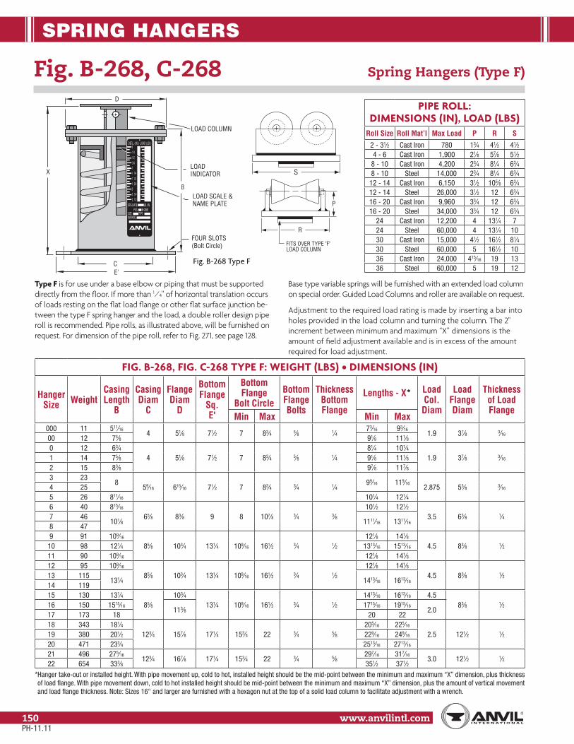
SPRING HANGERS
www.anvilintl.com150
Fig. B-268, C-268 Spring Hangers (Type F)
PIPE ROLL: DIMENSIONS (IN), LOAD (LBS)
Roll Size Roll Mat’l Max Load P R S2 - 31⁄2 Cast Iron 780 13⁄4 41⁄2 41⁄24 - 6 Cast Iron 1,900 21⁄8 57⁄8 51⁄2
8 - 10 Cast Iron 4,200 23⁄4 81⁄4 63⁄48 - 10 Steel 14,000 23⁄4 81⁄4 63⁄4
12 - 14 Cast Iron 6,150 31⁄2 105⁄8 63⁄412 - 14 Steel 26,000 31⁄2 12 63⁄416 - 20 Cast Iron 9,960 33⁄4 12 63⁄416 - 20 Steel 34,000 33⁄4 12 63⁄4
24 Cast Iron 12,200 4 131⁄4 724 Steel 60,000 4 131⁄4 1030 Cast Iron 15,000 41⁄2 161⁄2 81⁄430 Steel 60,000 5 161⁄2 1036 Cast Iron 24,000 415⁄16 19 1336 Steel 60,000 5 19 12
FIG. B-268, FIG. C-268 TYPE F: WEIGHT (LBS) • DIMENSIONS (IN)
Hanger Size Weight
Casing Length
B
Casing Diam
C
Flange Diam
D
Bottom Flange
Sq. E'
Bottom Flange
Bolt CircleBottom Flange Bolts
Thickness Bottom Flange
Lengths - X* Load Col. Diam
Load Flange Diam
Thickness of Load Flange
Min Max Min Max000 11 511⁄16
4 51⁄8 71⁄2 7 83⁄4 5⁄8 1⁄473⁄16 93⁄16
1.9 37⁄8 3⁄1600 12 75⁄8 91⁄8 111⁄80 12 63⁄4
4 51⁄8 71⁄2 7 83⁄4 5⁄8 1⁄481⁄4 101⁄4
1.9 37⁄8 3⁄161 14 75⁄8 91⁄8 111⁄82 15 83⁄8 97⁄8 117⁄83 23
859⁄16 615⁄16 71⁄2 7 83⁄4 3⁄4 1⁄4
99⁄16 119⁄162.875 53⁄8 3⁄164 25
5 26 811⁄16 101⁄4 121⁄46 40 815⁄16
65⁄8 83⁄8 9 8 107⁄8 3⁄4 3⁄8101⁄2 121⁄2
3.5 63⁄8 1⁄47 46101⁄8 1111⁄16 1311⁄16
8 479 91 109⁄16
85⁄8 103⁄4 131⁄4 109⁄16 161⁄2 3⁄4 1⁄2121⁄8 141⁄8
4.5 83⁄8 1⁄210 98 121⁄4 1313⁄16 1513⁄16
11 90 109⁄16 121⁄8 141⁄812 95 109⁄16
85⁄8 103⁄4 131⁄4 109⁄16 161⁄2 3⁄4 1⁄2121⁄8 141⁄8
4.5 83⁄8 1⁄213 115131⁄4 1413⁄16 1613⁄16
14 11915 130 131⁄4
85⁄8103⁄4
131⁄4 109⁄16 161⁄2 3⁄4 1⁄21413⁄16 1613⁄16 4.5
83⁄8 1⁄216 150 1515⁄16113⁄8
1715⁄16 1915⁄162.0
17 173 18 20 2218 343 181⁄4
123⁄4 157⁄8 171⁄4 153⁄4 22 3⁄4 5⁄8205⁄16 225⁄16
2.5 121⁄2 1⁄219 380 201⁄2 229⁄16 249⁄16
20 471 233⁄4 2513⁄16 2713⁄16
21 496 275⁄16123⁄4 167⁄8 171⁄4 153⁄4 22 3⁄4 5⁄8
297⁄16 317⁄163.0 121⁄2 1⁄2
22 654 333⁄8 351⁄2 371⁄2* Hanger take-out or installed height. With pipe movement up, cold to hot, installed height should be the mid-point between the minimum and maximum “X” dimension, plus thickness of load flange. With pipe movement down, cold to hot installed height should be mid-point between the minimum and maximum “X” dimension, plus the amount of vertical movement and load flange thickness. Note: Sizes 16" and larger are furnished with a hexagon nut at the top of a solid load column to facilitate adjustment with a wrench.
Type F is for use under a base elbow or piping that must be supported directly from the floor. If more than 1⁄4" of horizontal translation occurs of loads resting on the flat load flange or other flat surface junction be-tween the type F spring hanger and the load, a double roller design pipe roll is recommended. Pipe rolls, as illustrated above, will be furnished on request. For dimension of the pipe roll, refer to Fig. 271, see page 128.
Base type variable springs will be furnished with an extended load column on special order. Guided Load Columns and roller are available on request. Adjustment to the required load rating is made by inserting a bar into holes provided in the load column and turning the column. The 2" increment between minimum and maximum “X” dimensions is the amount of field adjustment available and is in excess of the amount required for load adjustment.
MARKNO.SIZE TYPE
FIG. B-268SPG.RATE LB./IN.
1/4113/41/21/40
2 1/2
1/213/41
21/42
DEFL. (IN.) LOAD (LB.)
E'C
X
LOAD SCALE &NAME PLATE
LOADINDICATOR
D
LOAD COLUMN
B
FOUR SLOTS(Bolt Circle)
P
R
FITS OVER TYPE "F"LOAD COLUMN
S
Fig. B-268 Type F
PH-11.11

SPRING HANGERS
Stra
psSp
ring
Hang
ers
Cons
tant
Supp
orts
Vibr
ation
Con
trol
& Sw
ay B
race
Sway
Stru
tAs
sem
bly
Snub
bers
Appl
icatio
nEx
ampl
esSp
ecial
Des
ign
Prod
ucts
Trap
eze
Pipe
Rol
lPi
pe G
uide
s&
Slid
esPi
pe S
hield
s&
Sadd
lesPi
peSu
ppor
tsIn
dex
www.anvilintl.com 151
Tech
nica
lDa
taM
aster
For
mat
3 Pa
rt Sp
ecs.
FIG. B-268, C-268 TYPE G: WEIGHT (LBS) • DIMENSIONS (IN)
Hanger Size Weight*
Rod Size
A
R.H. Thread Length
Casing Length
B
Casing Dia.
C
Flange Dia.
D
Min Thread
Engagement F
Rod Take Out N
Channel Size
(lb/ft)
Max C-C
Space Between Channels
W
P Z
000 241⁄2 5
53⁄84 51⁄8 15⁄16
13⁄8C3 x 4.1 24 5⁄8 11⁄2
13⁄16
00 26 79⁄16 13⁄4 13⁄16
0 301⁄2 5
611⁄16
4 51⁄8 15⁄1615⁄16
C3 x 4.1 24 5⁄8 11⁄23⁄4
1 31 79⁄16
2 32 85⁄16 19⁄16 13 41
1⁄2 5715⁄16
59⁄16 615⁄16 15⁄16
21⁄16
C3 x 4.1 30 3⁄4 21
4 42 27⁄16 13⁄85 43 85⁄8 13⁄4 11⁄16
6 635⁄8 5
813⁄16
65⁄8 83⁄8 15⁄16
15⁄8C3 x 4.1 36 1 2
9⁄16
7 6910 111⁄16 5⁄8
8 739 143
3⁄4 6107⁄16
85⁄8 103⁄4 11⁄421⁄2
C4 x 5.4 36 11⁄4 3
3⁄410 157 121⁄8 31⁄4 11⁄211 145 107⁄16 37⁄16 111⁄16
12 1571
6 107⁄16
85⁄8 103⁄4 11⁄4313⁄16
C5 x 6.736
11⁄2 311⁄16
13 1957
131⁄8 31⁄4 1⁄214 203 11⁄4 131⁄4 31⁄8 33 3⁄815 250 11⁄4 7 131⁄4
85⁄8103⁄4
115⁄16
315⁄16 C6 x 10.536
11⁄23
3⁄816 298 11⁄2
8161⁄16
113⁄841⁄8
C8 x 11.5 21⁄821⁄16
17 354 13⁄4 181⁄8 4 115⁄16
18 690 29
181⁄4123⁄4 157⁄8 23⁄4
4C12 x 20.7
4223⁄8
329⁄16
19 783 21⁄4 201⁄241⁄8
25⁄8211⁄16
20 993 21⁄2 10 233⁄4 40 27⁄821 1,197 23⁄4 10 275⁄16
123⁄4 167⁄8 35⁄845⁄16
C15 x 33.9 4831⁄8
3311⁄16
22 1,496 3 11 333⁄8 43⁄8 33⁄8 33⁄4
* Weight based on 24" center-to-center dimension
Fig. B-268, Fig. C-268 Spring Hangers (Type G)
Type G is a complete trapeze assembly. The hanger consists of two standard spring units plus a pair of back-to-back channels welded at each end to the hanger casing. The “P” dimension can be varied with the customer’s instructions. In sizing a Type G hanger, it must be remembered that each standard spring unit carries one-half of the total pipe load. Therefore, in using the hanger selection chart, use one-half of the total pipe load as the hot load. When the pipe line is designed so as not to be centered on the channel, one spring of the trapeze will carry a heavier load, the other a lighter load. Care should be taken in calculating the load of each hanger and in choosing the proper sized spring in such cases. The center-to-center rod dimension must be specified when ordering.
DEFL. (IN.) LOAD (LB.)
2 1/421 3/41 1/2
1/22
01/41/23/411 1/4
SPG.RATE LB./IN.
FIG. B-268SIZE TYPE GMARKNO.
C
D
B
F
N
C-C ROD DIMENSIONAS SPECIFIED
ROD SIZE "A"ROD NOT FURNISHEDLENGTH OF R.H. TH'DSEE TABLE BELOW
W
LOAD INDICATOR
MIN = ZMAX = Z + 3 1/2"
P
Fig. B-268 Type G
PH-11.11

SPRING HANGERS
www.anvilintl.com152
Fig. 82, C-82 Short Spring Hangers
The Anvil variable short spring hanger, Fig. 82, embodies all of the Fig. B-268 features and is designed to the same exacting specifications. This is useful in confined areas where thermal movement of the piping is relatively small. The minimum and maximum loads for the individual sizes of the Fig. 82 are exactly the same as those for the Fig. B-268. This hanger is offered in the seven basic types as shown here. The load table and instructions for sizing and ordering this hanger are found on page 142 through 145.
C
B
D
F
E
G "A"
MIN.=ZMAX.=Z+13⁄4"
LOADINDICATOR
LOADSCALE &
NAME PLATE
"A"
01/41/23/411 1/4
DEFL. (IN.) LOAD (LB.)SPG.RATE LB./IN.
FIG. -82SIZE TYPEMARKNO.
D
T
F
C
J
H
R
MIN.=ZMAX.=Z+13⁄4"
"A"
LOADSCALE &
NAME PLATELOADINDICATOR
01/41/23/411 1/4
DEFL. (IN.) LOAD (LB.)SPG.RATE LB./IN.
FIG. -82SIZE TYPEMARKNO.
B
DT
S
H
R
B
MIN.=ZMAX.=Z+13⁄4"
LOADINDICATOR
F
J
C
"A"
LOADSCALE &
NAME PLATE
01/41/23/411 1/4
DEFL. (IN.) LOAD (LB.)SPG.RATE LB./IN.
FIG. -82SIZE TYPEMARKNO.
01/41/23/411 1/4
DEFL. (IN.) LOAD (LB.)SPG.RATE LB./IN.
FIG. -82SIZE TYPEMARKNO.
M
K D
Y
C
B
"A"LOAD
SCALE &NAME PLATE
LOADINDICATOR
D
B
C
ROD SIZE "A"
FIELD PINNEDOR TACKED
LOADINDICATOR 0
1/41/23/411 1/4
DEFL. (IN.) LOAD (LB.)SPG.RATE LB./IN.
FIG. -82SIZE TYPEMARKNO.
LOADSCALE &
NAME PLATE
13⁄4"
COUPLINGPOSITIONAT MAX LOAD
R.H. TH'DS.
FIELDPINNED
F
Q
F
E'C
X
D
LOAD COLUMN
B
FOURSLOTS
01/41/23/411 1/4
DEFL. (IN.) LOAD (LB.)SPG.RATE LB./IN.
FIG. -82SIZE TYPEMARKNO.
LOADSCALE &
NAME PLATE
LOADINDICATOR
01/41/23/411 1/4
DEFL. (IN.) LOAD (LB.)SPG.RATE LB./IN.
FIG. -82SIZE TYPEMARKNO.
C
D
B
F
N
C - C ROD DIMENSIONAS SPECIFIED
W
LOAD INDICATOR
MIN = ZMAX = Z + 13⁄4"
P
"A"
Fig. 82 Type G
Fig. 82 Type A Fig. 82 Type B Fig. 82 Type C
Fig. 82 Type D Fig. 82 Type E Fig. 82 Type F
PH-11.11

SPRING HANGERS
Stra
psSp
ring
Hang
ers
Cons
tant
Supp
orts
Vibr
ation
Con
trol
& Sw
ay B
race
Sway
Stru
tAs
sem
bly
Snub
bers
Appl
icatio
nEx
ampl
esSp
ecial
Des
ign
Prod
ucts
Trap
eze
Pipe
Rol
lPi
pe G
uide
s&
Slid
esPi
pe S
hield
s&
Sadd
lesPi
peSu
ppor
tsIn
dex
www.anvilintl.com 153
Tech
nica
lDa
taM
aster
For
mat
3 Pa
rt Sp
ecs.
FIG. 82, C-82 SHORT SPRING: WEIGHT (LBS) • DIMENSIONS (IN)
Hanger Size
Rod Size
A
R.H. Thread Length
CasingFlange
Dia. D
Min Thread Engage
F
Z
Rod Take Out By Type Type A Types B, C Type D
Length B
Dia. C
A B,C E G Thread Depth G
Lug Hole Size
Pin Hgh H R
Clevis Open-ing S
Thk. TRod
Length Y
Nut Allow.
K
Height Spacer
ME J Q N
01⁄2 3
43⁄44 51⁄8 15⁄16
15⁄16 45⁄16 61⁄421⁄8
17⁄16 11⁄16 11⁄2 11⁄4 7⁄8 1⁄4
71⁄211⁄4 13⁄41 11⁄16 41⁄16 6 3⁄4 73⁄4
2 53⁄8 11⁄16 51⁄16 7 11⁄8 83⁄83
1⁄2 351⁄4
59⁄16 615⁄16 15⁄16
9⁄16 47⁄16 63⁄821⁄8
5⁄87⁄16 11⁄16 11⁄2 11⁄4 7⁄8 1⁄4
77⁄811⁄4 13⁄44 51⁄4 13⁄16
51⁄16 711⁄4 81⁄4
5 53⁄8 11⁄16 11⁄8 85⁄86
5⁄8 3513⁄16
65⁄8 83⁄8 15⁄16
13⁄16 51⁄16 73⁄16
21⁄817⁄8
5⁄8 13⁄16 11⁄2 11⁄4 11⁄16 1⁄491⁄16
11⁄2 13⁄47611⁄16
11⁄16 63⁄16 85⁄16 21⁄8 911⁄16
8 13⁄16 515⁄16 81⁄16 17⁄8 915⁄16
93⁄4 4
71⁄485⁄8 103⁄4 11⁄4
11⁄8 61⁄8 85⁄82
17⁄81 15⁄16 11⁄2 11⁄4 11⁄4 3⁄8
111⁄413⁄4 13⁄410 81⁄4 13⁄8 73⁄8 97⁄8 21⁄8 113⁄4
11 71⁄4 13⁄16 63⁄16 811⁄16 115⁄16 107⁄16
121
471⁄4
85⁄8 103⁄4 11⁄4
7⁄8 63⁄16 811⁄16
211⁄8
111⁄4 2 11⁄2 15⁄8 1⁄2
111⁄421⁄4
13⁄413 83⁄4 1 73⁄8 103⁄8 23⁄4 125⁄814 11⁄4 87⁄8 3⁄4 73⁄8 113⁄8 21⁄2 11⁄2 3 2 2 5⁄8 135⁄8 315 11⁄4 4 87⁄8
85⁄8103⁄4 11⁄4 3⁄4 73⁄8 113⁄8 2 21⁄2 1 11⁄2
32 2 5⁄8 141⁄8 3
13⁄416 11⁄2 5 105⁄8113⁄8 115⁄16 2
95⁄16 1311⁄166
11⁄1613⁄8
13⁄421⁄2
23⁄8 3⁄4157⁄8 31⁄2
17 13⁄4 6 117⁄8 109⁄16 1415⁄16 21⁄16 2 25⁄8 175⁄8 418 2
713
123⁄4 157⁄8 23⁄421⁄2 1011⁄16 1613⁄16
6
7⁄16
21⁄423⁄8 4
327⁄8 3⁄4
193⁄16 49⁄16
13⁄419 21⁄4 14 29⁄16 113⁄4 183⁄8 1 25⁄841⁄2
31⁄8 205⁄8 520 21⁄2 8 161⁄8 211⁄16 14 205⁄8 11⁄8 27⁄8 4 33⁄8 1 235⁄16 59⁄16
21 23⁄4 9 18123⁄4 167⁄8 35⁄8 23⁄4
135⁄8 207⁄87
3⁄8 23⁄4 31⁄8 41⁄24
35⁄81
25 61⁄4 11⁄422 3 10 221⁄4 175⁄8 253⁄8 23⁄8 3 33⁄8 5 37⁄8 295⁄8 65⁄8 13⁄4
Hanger Size
Type F Type G Weight
E' Bottom Flange Bottom Flange
Load Col. Dia.
Load Flange Length X ■ Channel
Size (lbs/ft)
Max C-C
Space Between
Channels - W
PType
Size Sq.
Bolt Circle
Min Max Bolts Thick Dia. Thick Min Max A,B,C D,E F G*
071⁄2 7 83⁄4 5⁄8 1⁄4 1.900 37⁄8 3⁄16
65⁄16 613⁄16 C3 x 4.1 24 5⁄8 3⁄46 5 11 27
1 7 6 11 292 615⁄16 77⁄16 8 7 123
71⁄2 7 83⁄4 3⁄4 1⁄4 2.875 53⁄8 3⁄1667⁄8 73⁄8 C3 x 4.1 30 3⁄4 3⁄4
11 10 10 334 12 11 20 355 7 71⁄2 13 12 21 366
9 8 107⁄8 3⁄4 3⁄8 3.50 63⁄8 1⁄471⁄2 8
C3 x 4.1 36 1 3⁄420 19 33 51
7 83⁄8 87⁄8 23 22 35 578 24 23 36 599
131⁄4 109⁄16 161⁄2 3⁄4 1⁄2 4.50 83⁄8 1⁄2815⁄16 915⁄16
C4 x 5.4 36 11⁄4 156 52 78 125
10 915⁄16 1015⁄16 62 58 84 13711 815⁄16 915⁄16 55 51 76 12112
131⁄4 109⁄16 161⁄2 3⁄4 1⁄2 4.50 83⁄8 1⁄2815⁄16 915⁄16
C5 x 6.7 36 11⁄2 158 53 78 132
13 107⁄16 117⁄16 69 63 81 15414 109⁄16 119⁄16 33 72 55 91 15915
131⁄4 109⁄16 161⁄2 3⁄4 1⁄24.50
83⁄8 1⁄2109⁄16 119⁄16 C6 x 10.5
3611⁄2
188 79 100 198
16 2.00 125⁄8 135⁄8 C8 x 11.5 21⁄8 102 91 112 23017 137⁄8 147⁄8 120 105 126 26618
171⁄4 153⁄4 22 3⁄4 5⁄8 2.50 121⁄2 1⁄2151⁄16 161⁄16 – – – – 259 226 270 –
19 161⁄16 171⁄16 – – – – 286 246 275 –20 183⁄16 193⁄16 – – – – 350 302 344 –21 171⁄4 153⁄4 22 3⁄4 5⁄8 3.00 121⁄2 1⁄2 201⁄8 211⁄8 – – – – 401 339 348 –22 243⁄8 253⁄8 – – – – 490 431 443 –
■ Hanger take-out or installed height. With pipe movement up, cold to hot, installed height should be the mid point between the minimum and maximum “X” dimension, plus thickness of load flange. With pipe movement down, cold to hot installed height should be mid-point between the minimum and maximum “X” dimension, plus the amount of vertical movement and load flange thickness. (Type F only).
* Weight based on 24" center-to-center dimension. See page 150 for Type F roller and guided load column information.Attachment rods and nuts not furnished.
PH-11.11
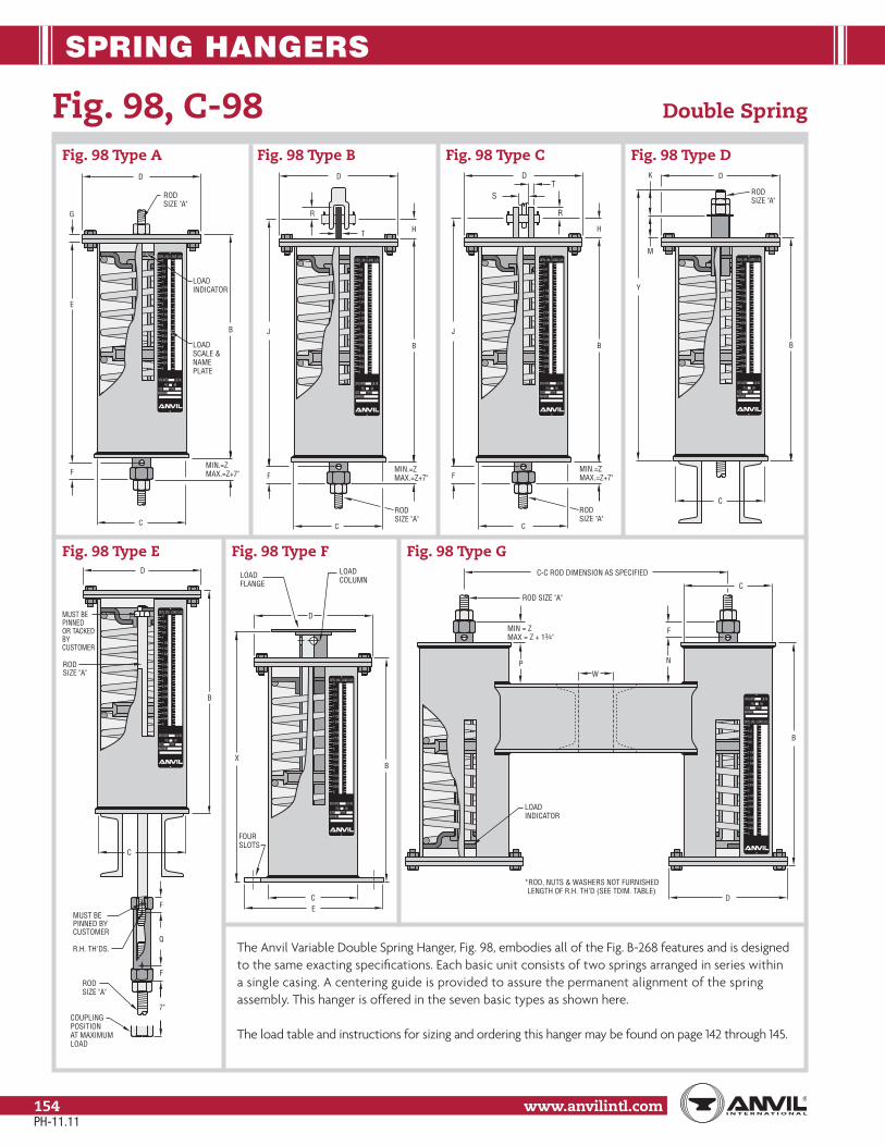
SPRING HANGERS
www.anvilintl.com154
Fig. 98, C-98 Double Spring
The Anvil Variable Double Spring Hanger, Fig. 98, embodies all of the Fig. B-268 features and is designed to the same exacting specifications. Each basic unit consists of two springs arranged in series within a single casing. A centering guide is provided to assure the permanent alignment of the spring assembly. This hanger is offered in the seven basic types as shown here.
The load table and instructions for sizing and ordering this hanger may be found on page 142 through 145.
Fig. 98 Type A
DEFL.(IN.) LOAD (LB.)
2 1/421 3/411/2
1/22
0
1/4
1/2
3/41
11/4
SPG.RATE LB./IN. FIG. -98
SIZE TYPEMARKNO.
3
33
31/4
5
4444
23/4
1/23/4
1/41/23/4
C
B
D
F
E
G
RODSIZE "A"
MIN.=ZMAX.=Z+7"
LOADINDICATOR
LOADSCALE &NAMEPLATE
D
T H
R
DEFL.(IN.) LOAD (LB.)
2 1/421 3/411/2
1/22
0
1/4
1/2
3/41
11/4
SPG.RATE LB./IN. FIG. -98
SIZE TYPEMARKNO.
3
33
31/4
5
4444
23/4
1/23/4
1/41/23/4
C
B
F
J
MIN.=ZMAX.=Z+7"
RODSIZE "A"
DT
S
R
DEFL.(IN.) LOAD (LB.)
2 1/421 3/411/2
1/22
0
1/4
1/2
3/41
11/4
SPG.RATE LB./IN. FIG. -98
SIZE TYPEMARKNO.
3
33
31/4
5
4444
23/4
1/23/4
1/41/23/4
C
F
J
RODSIZE "A"
H
B
MIN.=ZMAX.=Z+7"
M
K D
Y
C
RODSIZE "A"
DEFL.(IN.) LOAD (LB.)
2 1/421 3/411/2
1/22
0
1/4
1/2
3/41
11/4
SPG.RATE LB./IN. FIG. -98
SIZE TYPEMARKNO.
3
33
31/4
5
4444
23/4
1/23/4
1/41/23/4
B
Fig. 98 Type B Fig. 98 Type C Fig. 98 Type D
DEFL.(IN.) LOAD (LB.)
2 1/421 3/411/2
1/22
0
1/4
1/2
3/41
11/4
SPG.RATE LB./IN. FIG. -98
SIZE TYPEMARKNO.
3
33
31/4
5
4444
23/4
1/23/4
1/41/23/4
B
D
MUST BE PINNEDOR TACKEDBYCUSTOMER
7"COUPLINGPOSITIONAT MAXIMUMLOAD
R.H. TH'DS.
MUST BE PINNED BY CUSTOMER
F
Q
F
C
RODSIZE "A"
RODSIZE "A"
B
EC
X
D
LOADFLANGE
LOADCOLUMN
FOURSLOTS
DEFL.(IN.) LOAD (LB.)
2 1/421 3/411/2
1/22
0
1/4
1/2
3/41
11/4
SPG.RATE LB./IN. FIG. -98
SIZE TYPEMARKNO.
3
33
31/4
5
4444
23/4
1/23/4
1/41/23/4
DEFL.(IN.) LOAD (LB.)
2 1/421 3/411/2
1/22
0
1/4
1/2
3/41
11/4
SPG.RATE LB./IN. FIG. -98
SIZE TYPEMARKNO.
3
33
31/4
5
4444
23/4
1/23/4
1/41/23/4
C
D
B
F
N
C-C ROD DIMENSION AS SPECIFIED
ROD SIZE "A"
W
LOADINDICATOR
MIN = ZMAX = Z + 13⁄4"
P
*ROD, NUTS & WASHERS NOT FURNISHEDLENGTH OF R.H. TH’D (SEE TDIM. TABLE)
Fig. 98 Type E Fig. 98 Type F Fig. 98 Type G
PH-11.11

SPRING HANGERS
Stra
psSp
ring
Hang
ers
Cons
tant
Supp
orts
Vibr
ation
Con
trol
& Sw
ay B
race
Sway
Stru
tAs
sem
bly
Snub
bers
Appl
icatio
nEx
ampl
esSp
ecial
Des
ign
Prod
ucts
Trap
eze
Pipe
Rol
lPi
pe G
uide
s&
Slid
esPi
pe S
hield
s&
Sadd
lesPi
peSu
ppor
tsIn
dex
www.anvilintl.com 155
Tech
nica
lDa
taM
aster
For
mat
3 Pa
rt Sp
ecs.
FIG. 98, C-98 DOUBLE SPRING: WEIGHT (LBS) • DIMENSIONS (IN)
Hanger Size
Rod Size
A
R.H. Thread Length
CasingFlange
Dia. D
Min. Thread Engage
F
Z
Rod Take Out By Type Type A Types B, C Type D
Length B
Dia. C
A B, C E G Thread Depth
G
Lug Hole Size
Pin Hgt H
RClevis
Opening S
Thk. T
Rod Length
Y
Nut Allow.
K
Height Spacer
ME J Q N
01⁄2 9
125⁄84 51⁄8 15⁄16
15⁄16 123⁄16 141⁄89
11⁄27⁄16 11⁄16 11⁄2 11⁄4 7⁄8 1⁄4
193⁄811⁄4 51⁄21 143⁄8 15⁄16 1315⁄16 157⁄8 11⁄2 211⁄8
2 157⁄8 11⁄16 153⁄16 171⁄8 11⁄4 221⁄23
1⁄2 914
59⁄16 615⁄16 15⁄16
13⁄16 137⁄16 153⁄89
17⁄87⁄16 11⁄16 11⁄2 11⁄4 7⁄8 1⁄4
203⁄411⁄4 51⁄24 151⁄4 13⁄16 153⁄16 171⁄8 23⁄8 22
5 165⁄8 11⁄16 1515⁄16 177⁄8 13⁄4 233⁄86
5⁄8 91611⁄16
65⁄8 83⁄8 15⁄16
13⁄16 1515⁄16 181⁄16
917⁄8
5⁄8 13⁄16 11⁄2 11⁄4 11⁄16 1⁄42311⁄16
11⁄2 51⁄27 185⁄8 11⁄8 183⁄16 205⁄16 23⁄16 255⁄88 199⁄16 11⁄16 1811⁄16 2013⁄16 13⁄4 269⁄16
93⁄4
9203⁄16
85⁄8 103⁄4 11⁄4
15⁄16 187⁄8 213⁄89
211⁄16
1 15⁄16 11⁄2 11⁄4 11⁄4 3⁄8277⁄16
13⁄4 51⁄210 225⁄8 1 213⁄8 237⁄8 23⁄4 297⁄811 10 181⁄4 7⁄8 167⁄8 193⁄8 12 25⁄8 251⁄212
110
191⁄285⁄8 103⁄4 11⁄4
5⁄8 177⁄8 207⁄812
33⁄81
11⁄4 2 11⁄2 15⁄8 1⁄2271⁄4
21⁄451⁄213 243⁄4 3⁄4 231⁄4 261⁄4 31⁄2 323⁄8
14 11⁄4 247⁄8 1⁄2 231⁄8 271⁄8 31⁄4 11⁄2 3 2 2 5⁄8 333⁄8 315 11⁄4 10 247⁄8
85⁄8103⁄4
115⁄16
1⁄2 231⁄8 271⁄8 12 31⁄4 1 11⁄23
2 2 5⁄8333⁄4 3
51⁄216 11⁄2 11 297⁄8113⁄8
2 289⁄16 3215⁄167
41⁄1613⁄8
13⁄421⁄2
23⁄8 387⁄8 31⁄217 13⁄4 12 34 21⁄8 3213⁄16 373⁄16 43⁄16 2 25⁄8 3⁄4 431⁄2 418 2 12 331⁄4
123⁄4 157⁄8 23⁄4211⁄16 311⁄8 373⁄16
741⁄8
21⁄423⁄8 4
327⁄8 3⁄4
433⁄16 49⁄16
51⁄219 21⁄4 13 373⁄4 29⁄16 351⁄2 421⁄8 4 25⁄841⁄2
31⁄8 481⁄8 520 21⁄2 14 441⁄4 211⁄16 421⁄8 483⁄4 41⁄8 27⁄8 4 33⁄8 1 553⁄16 59⁄16
21 23⁄4 14 497⁄8123⁄4 167⁄8 35⁄8
211⁄16 457⁄16 5211⁄167
35⁄16 23⁄4 31⁄8 41⁄24
35⁄81
605⁄8 61⁄451⁄2
22 3 15 62 31⁄2 581⁄8 661⁄8 41⁄8 3 33⁄8 5 37⁄8 731⁄8 65⁄8
Hanger Size
Type F Type G Weight
E' Bottom Flange Bottom Flange
Load Col. Dia.
Load Flange Length X ■ Channel
Size (lbs/ft)
Max C-C
Space Between
Channels - W
PType
Size Sq.
Bolt Circle
Min Max Bolts Thick Dia. Thick Min Max A,B,C D,E F G*0
71⁄2 7 83⁄4 5⁄8 1⁄4 1.90 37⁄8 3⁄16
143⁄16 163⁄16
C3 x 4.1 24 5⁄8 11⁄212 12 20 37
1 1515⁄16 1715⁄16 14 14 21 412 177⁄16 197⁄16 16 16 23 453
71⁄2 7 83⁄4 3⁄4 1⁄4 2.88 53⁄4 3⁄16
155⁄8 175⁄8C3 x 4.1 30 3⁄4 2
22 21 35 554 167⁄8 187⁄8 25 24 39 615 181⁄4 201⁄4 27 26 41 656
9 8 107⁄8 3⁄4 3⁄8 3.50 63⁄8 1⁄4183⁄8 203⁄8
C3 x 4.1 36 1 241 40 62 93
7 205⁄16 225⁄16 49 48 72 1098 211⁄4 231⁄4 61 52 75 1339
131⁄4 109⁄16 161⁄2 3⁄4 1⁄2 4.50 83⁄8 1⁄2217⁄8 237⁄8
C4 x 5.4 36 11⁄4 397 94 136 207
10 245⁄16 265⁄16 114 108 150 24111 1915⁄16 2115⁄16 96 95 134 20912
131⁄4 109⁄16 161⁄2 3⁄4 1⁄2 4.50 83⁄8 1⁄2213⁄16 233⁄16
C5 x 6.7 36 11⁄2 4108 104 144 223
13 267⁄16 287⁄16 144 139 181 30514 269⁄16 289⁄16 33 153 147 188 32315
131⁄4 109⁄16 161⁄2 3⁄4 1⁄24.50
83⁄8 1⁄2269⁄16 289⁄16 C6 x 10.5
3611⁄2
4172 163 201 368
162.00 317⁄8 337⁄8 C8 x 11.5 21⁄8 218 202 241 462
17 36 38 273 247 287 57218
171⁄4 153⁄4 22 3⁄4 5⁄8 2.50 121⁄2 1⁄2355⁄16 375⁄16
C12 x 20.7 42 23⁄8 4512 477 550 1,056
19 3913⁄16 4113⁄16 600 548 624 1,23120 465⁄16 485⁄16 40 802 723 807 1,63321 171⁄4 153⁄4 22 3⁄4 5⁄8 3.00 121⁄2 1⁄2 517⁄8 537⁄8 C15 x 33.9 48 31⁄8 4 940 845 872 1,96522 64 66 33⁄8 1,240 1,140 1,184 2,566
■ Hanger take-out or installed height. With pipe movement up, cold to hot, installed height should be the mid point between the minimum and maximum “X” dimension, plus thickness of load flange. With pipe movement down, cold to hot installed height should be mid-point between the minimum and maximum “X” dimension, plus the amount of vertical movement and load flange thickness. (Type F only).
* Weight based on 24" center-to-center dimension. See page 150 for Type F roller and guided load column information.Attachment rods and nuts not furnished.
PH-11.11
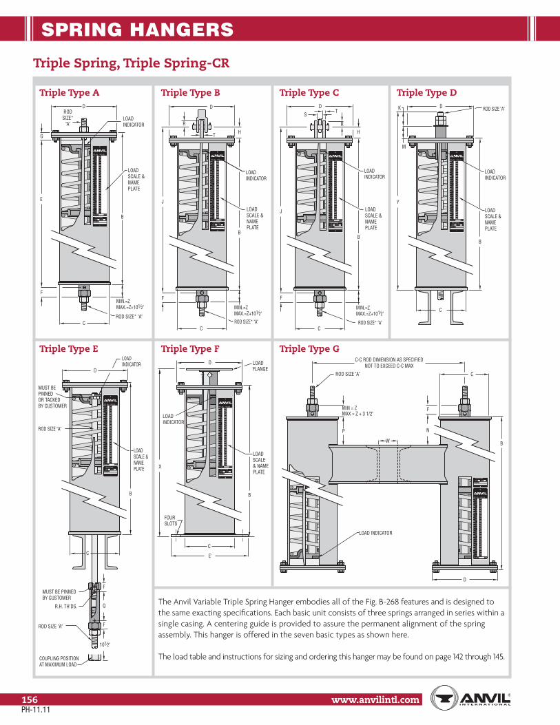
SPRING HANGERS
www.anvilintl.com156
Triple Spring, Triple Spring-CR
The Anvil Variable Triple Spring Hanger embodies all of the Fig. B-268 features and is designed to the same exacting specifications. Each basic unit consists of three springs arranged in series within a single casing. A centering guide is provided to assure the permanent alignment of the spring assembly. This hanger is offered in the seven basic types as shown here.
The load table and instructions for sizing and ordering this hanger may be found on page 142 through 145.
Triple Type A Triple Type B Triple Type C Triple Type D
Triple Type E Triple Type F Triple Type G
7 1/27 1/476 3/46 1/26 1/465 3/45 1/25 1/454 3/44 1/24 1/443 3/43 1/23 1/432 3/4
LB INSPG.RATE
1/23/411 1/4
1/40
TRIPLE SPRINGTYPESIZE
MARK NO.
1 1/21 3/4
2 1/42
2 1/2
DEFL.(IN) LOAD (LB)
G
D
LOADINDICATOR
E
LOADSCALE & NAMEPLATE
RODSIZE*
"A"
MIN.=ZMAX.=Z+101⁄2"
ROD SIZE* "A"C
F
B 7 1/27 1/476 3/46 1/26 1/465 3/45 1/25 1/454 3/44 1/24 1/443 3/43 1/23 1/432 3/4
LB INSPG.RATE
1/23/411 1/4
1/40
TRIPLE SPRINGTYPESIZE
MARK NO.
1 1/21 3/4
2 1/42
2 1/2
DEFL.(IN) LOAD (LB)
H
D
LOADINDICATOR
JLOADSCALE & NAMEPLATE
MIN.=ZMAX.=Z+101⁄2"
ROD SIZE* "A"C
F
B
R
T
MIN.=ZMAX.=Z+101⁄2"
B
7 1/27 1/476 3/46 1/26 1/465 3/45 1/25 1/454 3/44 1/24 1/443 3/43 1/23 1/432 3/4
LB INSPG.RATE
1/23/411 1/4
1/40
TRIPLE SPRINGTYPESIZE
MARK NO.
1 1/21 3/4
2 1/42
2 1/2
DEFL.(IN) LOAD (LB)
J
C
F
DT
S
HR
ROD SIZE* "A"
LOADINDICATOR
LOADSCALE & NAMEPLATE
7 1/27 1/476 3/46 1/26 1/465 3/45 1/25 1/454 3/44 1/24 1/443 3/43 1/23 1/432 3/4
LB INSPG.RATE
1/23/411 1/4
1/40
TRIPLE SPRINGTYPESIZE
MARK NO.
1 1/21 3/4
2 1/42
2 1/2
DEFL.(IN) LOAD (LB)
LOADINDICATOR
Y
LOADSCALE & NAMEPLATE
C
B
M
K D ROD SIZE "A"
7 1/27 1/476 3/46 1/26 1/465 3/45 1/25 1/454 3/44 1/24 1/443 3/43 1/23 1/432 3/4
LB INSPG.RATE
1/23/411 1/4
1/40
TRIPLE SPRINGTYPESIZE
MARK NO.
1 1/21 3/4
2 1/42
2 1/2
DEFL.(IN) LOAD (LB)
LOADINDICATOR
LOADSCALE & NAMEPLATE
C
B
D
MUST BE PINNEDOR TACKEDBY CUSTOMER
ROD SIZE "A"
101⁄2"
COUPLING POSITIONAT MAXIMUM LOAD
R.H. TH'DS.
MUST BE PINNEDBY CUSTOMER
F
Q
F
ROD SIZE "A"
7 1/27 1/476 3/46 1/26 1/465 3/45 1/25 1/454 3/44 1/24 1/443 3/43 1/23 1/432 3/4
LB INSPG.RATE
1/23/411 1/4
1/40
TRIPLE SPRINGTYPESIZE
MARK NO.
1 1/21 3/4
2 1/42
2 1/2
DEFL.(IN) LOAD (LB)
LOADSCALE& NAME PLATE
LOADFLANGE
C
B
X
D
LOADINDICATOR
E'
FOURSLOTS
LOAD INDICATOR
7 1/27 1/476 3/46 1/26 1/465 3/45 1/25 1/454 3/44 1/24 1/443 3/43 1/23 1/432 3/4
LB INSPG.RATE
1/23/411 1/4
1/40
TRIPLE SPRINGTYPESIZE
MARK NO.
1 1/21 3/4
2 1/42
2 1/2
DEFL.(IN) LOAD (LB)
C
D
B
F
N
C-C ROD DIMENSION AS SPECIFIEDNOT TO EXCEED C-C MAX
ROD SIZE "A"
W
MIN = ZMAX = Z + 3 1/2"
P
PH-11.11

SPRING HANGERS
Stra
psSp
ring
Hang
ers
Cons
tant
Supp
orts
Vibr
ation
Con
trol
& Sw
ay B
race
Sway
Stru
tAs
sem
bly
Snub
bers
Appl
icatio
nEx
ampl
esSp
ecial
Des
ign
Prod
ucts
Trap
eze
Pipe
Rol
lPi
pe G
uide
s&
Slid
esPi
pe S
hield
s&
Sadd
lesPi
peSu
ppor
tsIn
dex
www.anvilintl.com 157
Tech
nica
lDa
taM
aster
For
mat
3 Pa
rt Sp
ecs.
Triple Spring, Triple Spring-CR
TRIPLE SPRING: DIMENSIONS (IN)
Hanger Size
General Dimensions Rod Take Out For Types Type A Type D Type F Type
G
Rod Size
A
R.H. Thread Length
Casing Length
B
Casing Dia.
C
Min Thread
FZ
A B & C D E G Depth Thread
GK M
Loaded Length Dim X P
E J Y Q N Min Max
0
1⁄2 12
191⁄8
4 15⁄16 15⁄16
191⁄8 205⁄8 281⁄8
111⁄8 11⁄2 7⁄16 11⁄4 73⁄4
2015⁄16 2215⁄16
11⁄21 213⁄4 213⁄4 231⁄4 303⁄4 239⁄16 259⁄16
2 24 24 251⁄2 33 2513⁄16 279⁄16
3
1⁄2 12
213⁄16
59⁄16 15⁄16 15⁄16
213⁄16 2211⁄16 303⁄16
111⁄8 2 7⁄16 11⁄4 73⁄4
23 25
24 231⁄16 231⁄16 249⁄16 321⁄16 247⁄8 267⁄8
5 251⁄8 251⁄8 265⁄8 341⁄8 2615⁄16 2815⁄16
6
5⁄8
12 25
65⁄8 15⁄16 15⁄16
25 261⁄2 343⁄16
111⁄8 2 5⁄8 11⁄2 711⁄16
2615⁄16 2815⁄16
2713
2715⁄16 2715⁄16 297⁄16 371⁄8 297⁄8 317⁄8
8 295⁄16 295⁄16 3013⁄16 381⁄2 311⁄4 331⁄4
9
3⁄4 13
299⁄16
85⁄8 11⁄4 11⁄4
299⁄16 311⁄16 387⁄8
111⁄2 3 113⁄4
79⁄16
315⁄8 335⁄8
310 331⁄4 331⁄4 343⁄4 429⁄16 355⁄16 375⁄16
11 2611⁄16 2611⁄16 283⁄16 36 2 283⁄4 303⁄4
121
13 289⁄16
85⁄811⁄4
11⁄4
289⁄16 309⁄16 383⁄8
111⁄237⁄8
1
21⁄4
79⁄16
305⁄8 325⁄8
41314
361⁄4 361⁄4 381⁄4 461⁄16
21⁄2385⁄16 405⁄16
14 11⁄4 363⁄4 13⁄8 363⁄4 395⁄8 475⁄16 4 3813⁄16 4013⁄16
15 11⁄4 14 365⁄8
85⁄8
13⁄8 11⁄4 365⁄8 391⁄2 473⁄16 109⁄16
4 13⁄8
3 79⁄16 3811⁄16 4011⁄16
416 11⁄215
441⁄16
115⁄16 115⁄16
441⁄16 471⁄16 545⁄8 111⁄16 31⁄271⁄16
461⁄8 481⁄8
17 13⁄4 501⁄4 501⁄4 531⁄4 615⁄16 119⁄16 4 525⁄16 545⁄16
18 216
491⁄8
123⁄4 23⁄4 23⁄4
491⁄8 531⁄8 6011⁄16 107⁄8
4 21⁄4
49⁄16
7
515⁄16 535⁄16
419 21⁄4 557⁄8 557⁄8 603⁄8 677⁄8 117⁄16 5 581⁄16 601⁄16
20 21⁄2 17 655⁄8 655⁄8 701⁄8 783⁄16 1115⁄16 59⁄16 6713⁄16 6913⁄16
21 23⁄4 17 735⁄16
123⁄4 35⁄8 35⁄8735⁄16 7613⁄16 877⁄8 11
423⁄4 61⁄4
95⁄16
757⁄16 777⁄16
422 3 18 911⁄2 911⁄2 951⁄2 1067⁄16 111⁄2 3 65⁄8 935⁄8 955⁄8
Attachment rods and nuts not furnished. See page 150 for Type F roller and guided load column information.
See Fig. B-268 for dimensions not listed
PH-11.11

SPRING HANGERS
www.anvilintl.com158
Quadruple Spring, Quadruple Spring-CR
The Anvil Variable Quadruple Spring Hanger embodies all of the Fig. B-268 features and is designed to the same exacting specifications. Each basic unit consists of four springs arranged in series within a single casing. A centering guide is provided to assure the permanent alignment of the spring assembly. This hanger is offered in the seven basic types as shown here.
The load table and instructions for sizing and ordering this hanger may be found on page 142 through 145.
Quadruple Type A Quadruple Type B Quadruple Type C Quadruple Type D
Quadruple Type E Quadruple Type F Quadruple Type G
SPG.RATE LB IN/
MARK NO.SIZE TYPE
QUADRUPLE SPRING
109 3/49 1/29 1/498 3/48 1/28 1/487 3/47 1/27 1/476 3/46 1/26 1/465 3/45 1/25 1/454 3/44 1/24 1/443 3/43 1/23 1/432 3/4
DEFL.(IN) LOAD (LB)
1/23/411 1/4
1/40
1 1/21 3/4
2 1/42
2 1/2
G
D
LOADINDICATOR
E
LOAD SCALE & NAME PLATE
RODSIZE*
"A"
MIN.=ZMAX.=Z+14"
ROD SIZE* "A"C
F
B
SPG.RATE LB IN/
MARK NO.SIZE TYPE
QUADRUPLE SPRING
109 3/49 1/29 1/498 3/48 1/28 1/487 3/47 1/27 1/476 3/46 1/26 1/465 3/45 1/25 1/454 3/44 1/24 1/443 3/43 1/23 1/432 3/4
DEFL.(IN) LOAD (LB)
1/23/411 1/4
1/40
1 1/21 3/4
2 1/42
2 1/2
H
D
LOADINDICATOR
JLOADSCALE& NAME PLATE
F
B
R
T
MIN.=ZMAX.=Z+14"
CROD SIZE* "A"
SPG.RATE LB IN/
MARK NO.SIZE TYPE
QUADRUPLE SPRING
109 3/49 1/29 1/498 3/48 1/28 1/487 3/47 1/27 1/476 3/46 1/26 1/465 3/45 1/25 1/454 3/44 1/24 1/443 3/43 1/23 1/432 3/4
DEFL.(IN) LOAD (LB)
1/23/411 1/4
1/40
1 1/21 3/4
2 1/42
2 1/2
J
MIN.=ZMAX.=Z+14"F
B
DT
S
H
R
LOADINDICATOR
CROD SIZE* "A"
LOADSCALE& NAME PLATE
SPG.RATE LB IN/
MARK NO.SIZE TYPE
QUADRUPLE SPRING
109 3/49 1/29 1/498 3/48 1/28 1/487 3/47 1/27 1/476 3/46 1/26 1/465 3/45 1/25 1/454 3/44 1/24 1/443 3/43 1/23 1/432 3/4
DEFL.(IN) LOAD (LB)
1/23/411 1/4
1/40
1 1/21 3/4
2 1/42
2 1/2
Y
C
M
K D ROD SIZE "A"
B
LOADINDICATOR
LOADSCALE& NAME PLATE
SPG.RATE LB IN/
MARK NO.SIZE TYPE
QUADRUPLE SPRING
109 3/49 1/29 1/498 3/48 1/28 1/487 3/47 1/27 1/476 3/46 1/26 1/465 3/45 1/25 1/454 3/44 1/24 1/443 3/43 1/23 1/432 3/4
DEFL.(IN) LOAD (LB)
1/23/411 1/4
1/40
1 1/21 3/4
2 1/42
2 1/2
C
DLOADINDICATOR
LOADSCALE& NAME PLATE
B
MUST BE PINNEDOR TACKEDBY CUSTOMER
ROD SIZE "A"
14"COUPLING POSITIONAT MAXIMUM LOAD
R.H. TH'DS.
MUST BE PINNEDBY CUSTOMER
F
Q
F
ROD SIZE "A"
SPG.RATE LB IN/
MARK NO.SIZE TYPE
QUADRUPLE SPRING
109 3/49 1/29 1/498 3/48 1/28 1/487 3/47 1/27 1/476 3/46 1/26 1/465 3/45 1/25 1/454 3/44 1/24 1/443 3/43 1/23 1/432 3/4
DEFL.(IN) LOAD (LB)
1/23/411 1/4
1/40
1 1/21 3/4
2 1/42
2 1/2
LOADSCALE& NAME PLATE
LOADFLANGE
C
BX
D
LOADINDICATOR
E'
FOURSLOTS
C-C ROD DIMENSION AS SPECIFIEDNOT TO EXCEED C-C MAX
LOAD INDICATOR
C
D
B
F
N
ROD SIZE "A"
MIN = ZMAX = Z + 3 1/2"
P
7 1/27 1/476 3/46 1/26 1/465 3/45 1/25 1/454 3/44 1/24 1/443 3/43 1/23 1/432 3/4
LB INSPG.RATE
1/23/411 1/4
1/40
TRIPLE SPRINGTYPESIZE
MARK NO.
1 1/21 3/4
2 1/42
2 1/2
DEFL.(IN) LOAD (LB)
W
PH-11.11
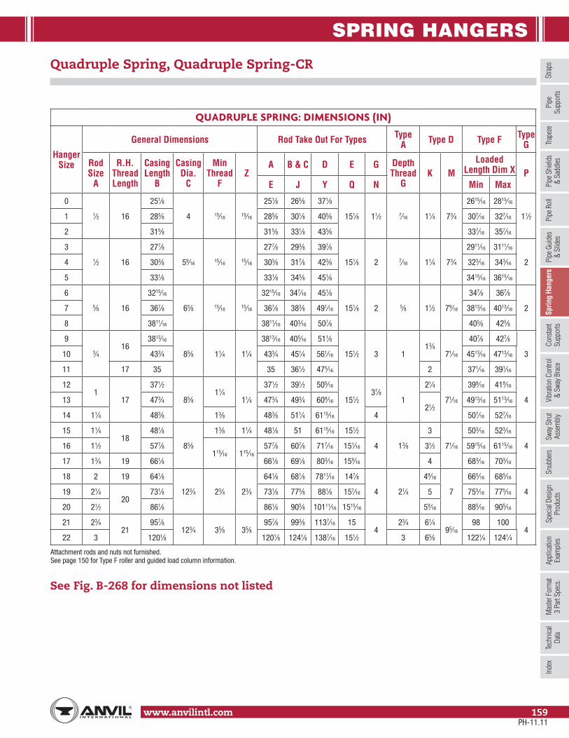
SPRING HANGERS
Stra
psSp
ring
Hang
ers
Cons
tant
Supp
orts
Vibr
ation
Con
trol
& Sw
ay B
race
Sway
Stru
tAs
sem
bly
Snub
bers
Appl
icatio
nEx
ampl
esSp
ecial
Des
ign
Prod
ucts
Trap
eze
Pipe
Rol
lPi
pe G
uide
s&
Slid
esPi
pe S
hield
s&
Sadd
lesPi
peSu
ppor
tsIn
dex
www.anvilintl.com 159
Tech
nica
lDa
taM
aster
For
mat
3 Pa
rt Sp
ecs.
Quadruple Spring, Quadruple Spring-CR
QUADRUPLE SPRING: DIMENSIONS (IN)
Hanger Size
General Dimensions Rod Take Out For Types Type A Type D Type F Type
G
Rod Size
A
R.H. Thread Length
Casing Length
B
Casing Dia.
C
Min Thread
FZ
A B & C D E G Depth Thread
GK M
Loaded Length Dim X P
E J Y Q N Min Max
0
1⁄2 16
251⁄8
4 15⁄16 15⁄16
251⁄8 265⁄8 371⁄8
151⁄8 11⁄2 7⁄16 11⁄4 73⁄4
2615⁄16 2815⁄16
11⁄21 285⁄8 285⁄8 301⁄8 405⁄8 307⁄16 327⁄16
2 315⁄8 315⁄8 331⁄8 435⁄8 337⁄16 357⁄16
3
1⁄2 16
277⁄8
59⁄16 15⁄16 15⁄16
277⁄8 293⁄8 397⁄8
151⁄8 2 7⁄16 11⁄4 73⁄4
2911⁄16 3111⁄16
24 303⁄8 303⁄8 317⁄8 423⁄8 323⁄16 343⁄16
5 331⁄8 331⁄8 345⁄8 451⁄8 3415⁄16 3615⁄16
6
5⁄8 16
3215⁄16
65⁄8 15⁄16 15⁄16
3215⁄16 347⁄16 451⁄8
151⁄8 2 5⁄8 11⁄2 79⁄16
347⁄8 367⁄8
27 367⁄8 367⁄8 383⁄8 491⁄16 3813⁄16 4013⁄16
8 3811⁄16 3811⁄16 403⁄16 507⁄8 405⁄8 425⁄8
9
3⁄416
3813⁄16
85⁄8 11⁄4 11⁄4
3813⁄16 405⁄16 511⁄8
151⁄2 3 113⁄4
71⁄16
407⁄8 427⁄8
310 433⁄4 433⁄4 451⁄4 561⁄16 4513⁄16 4713⁄16
11 17 35 35 361⁄2 475⁄16 2 371⁄16 391⁄16
121
17
371⁄2
85⁄811⁄4
11⁄4
371⁄2 391⁄2 505⁄16
151⁄237⁄8
1
21⁄4
71⁄16
399⁄16 419⁄16
413 473⁄4 473⁄4 493⁄4 609⁄16
21⁄24913⁄16 5113⁄16
14 11⁄4 483⁄8 13⁄8 483⁄8 511⁄4 6115⁄16 4 507⁄16 527⁄16
15 11⁄418
481⁄8
85⁄8
13⁄8 11⁄4 481⁄8 51 6115⁄16 151⁄2
4 13⁄8
3
71⁄16
503⁄16 523⁄16
416 11⁄2 577⁄8115⁄16 115⁄16
577⁄8 607⁄8 717⁄16 151⁄16 31⁄2 5915⁄16 6115⁄16
17 13⁄4 19 661⁄8 661⁄8 691⁄8 803⁄16 159⁄16 4 683⁄16 703⁄16
18 2 19 641⁄8
123⁄4 23⁄4 23⁄4
641⁄8 681⁄8 7811⁄16 147⁄8
4 21⁄4
49⁄16
7
665⁄16 685⁄16
419 21⁄420
731⁄8 731⁄8 775⁄8 881⁄8 157⁄16 5 755⁄16 775⁄16
20 21⁄2 861⁄8 861⁄8 905⁄8 10111⁄16 1515⁄16 59⁄16 885⁄16 905⁄16
21 23⁄421
957⁄8123⁄4 35⁄8 35⁄8
957⁄8 993⁄8 1137⁄16 154
23⁄4 61⁄495⁄16
98 1004
22 3 1201⁄8 1201⁄8 1241⁄8 1387⁄16 151⁄2 3 65⁄8 1221⁄4 1241⁄4
Attachment rods and nuts not furnished. See page 150 for Type F roller and guided load column information.
See Fig. B-268 for dimensions not listed
PH-11.11

CONSTANT SUPPORTS
www.anvilintl.com160
Model R Mathematically Perfect Pipe Support
The exclusive geometric design of Anvil Model R Constant Support Hanger assures perfectly constant support through the entire deflection of the pipe load. This counter-balancing of the load and spring moments about the main pivot is obtained by the use of carefully designed compression type load springs, lever, and spring tension rods.
As the lever moves from the high to the low position, the load spring is compressed and the resulting increasing force acting on the decreasing spring moment arm creates a turning moment about the main pivot which is exactly equal and opposite to the turning moment of the load and load moment arm.
As the lever moves from the low to the high position, the load spring is increasing in length and the resulting decreasing force acting on the increasing spring moment arm creates a turning moment about the main pivot which is exactly equal and opposite to the turning moment of the load and load moment arm.
The load “L” is suspended from the lever at point “A” and at any point within the load travel range the moment of the load about the main lever-pivot “P” is equal to the load times its moment arm, thus:
(4) Load moment = L (Wsinθ), where (Wsinθ) is the load moment arm
The spring is attached at one of its ends to the fixed pivot “B”. The spring’s free end is attached by means of a rod to the lever-pivot “D”. This spring arrangement provides a spring moment about the main lever-pivot “P” which opposes the load moment and is equal to the spring force “F” times its moment arm; thus: The spring and the rod are so arranged that the spring deflection “E”
always equals the distance “Δ” between pivots “B” and “D”. Therefore, equation (9) may be written as:
(10) LW = KYZ or, (11) L = (KYZ)/W
Since equation (11) holds true for all positions of the load within its travel range and “K”, “Y”, “Z”, and “W” remain constant it is therefore true that perfect constant support is obtained.
Substituting in (1), we have (2) X = sinφ and (3) X = YZsinφ
(5) Spring Moment = F(YZsinφ),
where (YZsinφ) is the spring moment arm
YZ Δ Δ
Δ
Δ
The spring force “F” is equal to the spring constant “K” times
the spring deflection “E”; thus:
(6) F = KE; Therefore equation (5) may be written as:
(7) Spring Moment = KE(YZsinφ)
(8) LW = (KEYZsinφ)
(9) LW = (KEYZ)
Δ
Δ
Δ
To obtain perfect constant support the load moment must always
equal the spring moment. Therefore:
By proper design “φ” and “θ” are made equal. Therefore, equation (8)
maybe written as:
MainPivot
LoadAdjustment
Bolt
MoveableSpring Pivot
SpringTension Rod
TrunionPlate
LoadSpring
FixedSpringPivot
Spring Cover
Position Indicatorand Travel Stop
K RodFrame
Load Scale
LoadYoke
LoadPivot
LoadCoupling
Lower"J" Rod
H M
L
9.921°
E
W SIN θ
HORIZONTAL
VERT
ICAL
θF
DB
Z P
A
LX
Δ
W
Yα
βφ
B P AL
D
EVR
CITAL
HORIZONTAL
L
AP
Y
F
Δ
D
φ θ
W SIN θ
E
WZ
BX
High Position Middle Position Low Position
(1) sinα = sinφ sinβ = X Y Δ
sinα = sinβ sinα = X Y Z Z
sinα = Ysinβ Z
PH-11.11

CONSTANT SUPPORTS
Stra
psSp
ring
Hang
ers
Cons
tant
Supp
orts
Vibr
ation
Con
trol
& Sw
ay B
race
Sway
Stru
tAs
sem
bly
Snub
bers
Appl
icatio
nEx
ampl
esSp
ecial
Des
ign
Prod
ucts
Trap
eze
Pipe
Rol
lPi
pe G
uide
s&
Slid
esPi
pe S
hield
s&
Sadd
lesPi
peSu
ppor
tsIn
dex
www.anvilintl.com 161
Tech
nica
lDa
taM
aster
For
mat
3 Pa
rt Sp
ecs.
Model R Fig. 80-V, C-80-V Vertical Constant Support
Model R Fig. 81-H, C-81-H Horizontal
Finish: Standard finish; painted with semi gloss primer. Corrosion resis-tant; galvanized with coated coil or painted with CZ11 and coated coil.Recommended Service: When piping stress is critical and pipe is subject to vertical movement in excess of 1⁄2" due to thermal expan-sion, and also at locations where it is necessary to avoid any transfer of stress from support or onto critical terminals or connecting equipment.Approvals: WW-H-171E (Types 52, 58 and 59), ANSI/MSS SP-69 and MSS SP-58 (Types 54, 55 and 56).Features:
• Because of exclusive geometric design, mathematically perfect constancy of support is maintained throughout the full range of load adjustment.• Compactness – design provides smaller and more versatile units.• Increased load and travel capacity.• Each hanger is individually calibrated before shipment to support the exact load specified.• All model R constant supports have a wide range of load adjustability. No less than 10% of this adjustability is provided either side of the calibrated load.• White button marked “C” denotes cold setting of hanger; red button marked “H” denotes hot or operating setting.• Field load adjustment is made by turning the single load adjustment bolt.• Covered spring provides protection and good appearance. • J-rod swings at least 4° from vertical.• Non-resonant to all vertical vibrations.
Size Range: Anvil Model R constant support hangers are made in two basic designs, 80- V (vertical design) and 81-H (horizontal design). Combined, the 80-V and 81-H constant supports are made in nine different frame sizes and 110 spring sizes to accommodate travels from 1 1⁄2" to 20" and loads from 27 lbs to 87,500 lbs.Single rod suspension: Available in Types A, B and C, Fig. 80-V (see page 178 through 170) and Fig. 81-H (see page 175 through 177).How to select hanger sizes: Determine the total load to be supported by the hanger as well as the actual travel – that is, the actual vertical movement of the pipe at the point of hanger location. Refer to the Load-Travel table for constant support hangers (see page 164 through 167) and select a size hanger which will accommodate the known load and actual travel. It must be noted that the travel shown in the table is a total travel – that is, the maximum vertical movement which the hanger will accommodate. The total travel of the hanger should always be greater than the calculated travel of pipe line to allow for some discrepancy between calculated travel and actual travel.It is suggested that the total travel for constant supports should be equal to “actual travel” plus 1" or 20% whichever is greater.How to determine type: After the size of the constant support is determined, consideration of available room for suspending the pipe and hanger will indicate whether a vertical (80-V series, page 168 - 174) or horizontal (81-H series, page 175 - 181) hanger is desirable.How to determine design: After the hanger size and design are determined, the type of constant support to be used depends upon the physical installation required by the suspension problem, i.e., whether the hanger is to be installed above, between or below steel members (see line cuts referring to Types A, B, C, etc.). It will be noted that the Type F is made in horizontal design only and the type G is made in the vertical design only. Special constant support hangers can be fabricated for unusual conditions.J-rod and K-hole diameter: Tapping or drilling for standard rod size will be furnished as shown in the J-rod and K-hole selection charts unless otherwise specified. Upper attachments, turnbuckles and clamps should be tapped to agree with the rod as shown in the selection chart. Standard rod diameters are based on the load to be carried by the upper rod which includes the weight of the hanger assembly as well as the pipe line. Tapped connections for hanger rod sizes 3" and smaller are UNC-Thread Series, Class 2 fit. 3 1⁄4" and large rod tappings are 8UN Series Threads.
Model R Fig. 81-H, Horizontal
Model R Fig. 80-V, Vertical
PH-11.11

CONSTANT SUPPORTS
www.anvilintl.com162
Model R (Continued)
Ordering: Specify:(1) Hanger size number(2) Figure number(3) Type(4) Name of hanger(5) Loads to be supported (pounds)(6) Total travel (inches)(7) Actual travel (inches)(8) Direction of movement “cold to hot”(9) Customer’s hanger mark.(10) When ordering Type G, specify C-C rod dimension as well as load per spring and total load.(11) For Types A, B, C, Fig. 81-H when required specify “for single rod suspension.”(12) Constant Support Hangers are also available corrosion-resistant as figures C-80-V and C-81-H.
Installation:(1) Securely attach the hanger to the building structure at a point where the load coupling is directly over the desired point of attachment to the pipe in the operating position.(2) Make certain that the moving parts of the hanger will be unobstructed.(3) Attach the lower J-rod between the pipe attachment and the load coupling. Make certain that the lower J-rod has enough thread engagement before taking up the load. A sight hole is provided for this.(4) Turn the load coupling, as you would a turnbuckle, until the travel indicator rotates to the desired cold setting (white button) marked “C” indicated on the position scale. If the constant support incorporates a travel stop see below.(5) After the line is in operation, check hanger for indicated hot setting. If necessary, make adjustment by turning the load coupling to bring the indicator to the hot position (red button) marked “H”. No other adjustment is normally required since the load as calibrated at the factory is equal to the load specified to be supported.
Adjustment: When the hanger is installed, its supporting force should be in balance with the portion of the piping weight assigned to it. Each hanger is individually calibrated before shipment to support the exact load specified. All model “R” Constant Supports have a wide range of load adjustability. Special instructions for field recalibration of individual hangers may be obtained from Anvil representatives. No less than 10% adjustability is provided either side of the calibrated load for plus or minus field load adjustment. The percentage increase or decrease from the factory calibrated load should be carefully calculated. The calibrated load setting of each hanger is indicated by a die-stamp on the load adjustment scale. Load adjustments should be made from this reference point, with each division on the patented scale equal to 2% except sizes 84-110 where each division is valued at 1%. The load adjustment is made by turning the single load adjustment bolt. For example, a calibrated load of 3,000 pounds revised to 2,760 pounds is a decrease of 240 pounds. 240/3,000 = 8%. By turning the load adjusting bolt the arrow moves in the “Decrease” direction four divisions.Note: Field Recalibration of load does not decrease total travel.
Travel stop: The functional design of the Constant Support Hanger permits the incorporation of a travel stop that will lock the hanger against upward or downward movement for temporary conditions of underload or overload, such as may exist during erection, hydrostatic test or chemical clean-out. Anvil Constant Supports are designed for hydrostatic test load of at least 2 times the normal operating load for the Constant Support. The travel stop for sizes 19 - 110 consists of two plates, with matched serrations, attached to the hanger frame with two or more cap screws and with a socketed piece which engages the position indicator. It is installed at the factory to hold the hanger in the “cold” position. A series of serrations can be engaged to lock the hanger at any position along the total travel range. The travel stop, which is furnished only when specified, is painted red. The stop must be removed before the piping system is put into operation, but not before the hanger is installed and fully loaded. The travel stop is released by removing the cap screws. A tag marked “Caution” and containing instructions for removal of the travel stop is attached to the hanger.Note: See installation procedures PE-217-80 for a travel stop description on sizes 1-18.
Load adjustment scale shown applies to size 1 through 83 only. The load adjustment scale for sizes 84 through 1101 division equals 1%.
PH-11.11

CONSTANT SUPPORTS
Stra
psSp
ring
Hang
ers
Cons
tant
Supp
orts
Vibr
ation
Con
trol
& Sw
ay B
race
Sway
Stru
tAs
sem
bly
Snub
bers
Appl
icatio
nEx
ampl
esSp
ecial
Des
ign
Prod
ucts
Trap
eze
Pipe
Rol
lPi
pe G
uide
s&
Slid
esPi
pe S
hield
s&
Sadd
lesPi
peSu
ppor
tsIn
dex
www.anvilintl.com 163
Tech
nica
lDa
taM
aster
For
mat
3 Pa
rt Sp
ecs.
Model R (Continued)
Model R lifting lugs: To help alleviate the problem of lifting large size Constant Supports into position for installation, this product is available with lifting lugs (if requested) on sizes ten and larger.
Fig. 80V (Vertical): Typical Applications
Fig. 81-H (Horizontal): Typical Applications
Lifting Lugs (Fig 80-V):
H M L
Lugs to be attached toeach side of frame (all types)
Hole
LUGS TO BE 90°FROM CHANNELON TYPE D 3"
Types A, B, C, D, & Esizes 10 thru 63
sizes 84 thru 110
sizes 64 thru 83Lugs to be attached toeach side of frame and
will need stabilizingrigging when being lifted
Type A Type B and Type C
Type D Type E
Type F
Lifting Lugs (Figure 81-H): Not available on Type F.
Type A Type B and Type C
Type D Type E Type G
PH-11.11

CONSTANT SUPPORTS
www.anvilintl.com164
Hanger Size No.
TOTAL TRAVEL* (IN); LOAD (LBS) SEE NOTES ON PAGE 16711⁄2 2 21⁄2 3 31⁄2 4 41⁄2 5 51⁄2 6 61⁄2 7 71⁄2 8 81⁄2
1144 108 86 72 62 54 48 43 39 36 33 31 29 27173 130 104 87 74 65 58 52 47 43 40 37 35 33
2 204 153 122 102 87 77 68 61 56 51 47 44 41 383 233 175 140 117 100 88 78 70 64 58 54 50 47 444 280 210 168 140 120 105 93 84 76 70 65 60 56 535 327 245 196 163 140 123 109 98 89 82 75 70 65 616 373 280 224 187 160 140 124 112 102 93 86 80 75 707 451 338 270 225 193 169 150 135 123 113 104 97 90 858 527 395 316 263 226 198 176 158 144 132 122 113 105 999 600 450 360 300 257 225 200 180 164 150 138 129 120 11310 727 545 436 363 311 273 242 218 198 182 168 156 145 13611 851 638 510 425 365 319 284 255 232 213 196 182 170 16012 977 733 586 489 419 367 326 293 267 244 226 209 195 18313 1,177 883 706 589 505 442 392 353 321 294 272 252 235 22114 1,373 1,030 824 687 589 515 458 412 375 343 317 294 275 25815 1,573 1,180 944 787 674 590 524 472 429 393 363 337 315 29516 1,893 1,420 1,136 947 811 710 631 568 516 473 437 406 379 35517 2,217 1,663 1,330 1,109 950 832 739 665 605 554 512 475 443 41618 2,540 1,905 1,524 1,270 1,089 953 847 762 693 635 586 544 508 476
19 2,025 1,620 1,350 1,157 1,013 900 810 736 675 623 579 540 506448476
20 2,145 1,716 1,430 1,226 1,073 953 858 780 715 660 613 572 536 50521 2,335 1,868 1,557 1,334 1,168 1,038 934 849 778 718 667 623 584 54922 2,525 2,020 1,683 1,443 1,263 1,122 1,010 918 842 777 721 673 631 59423 2,710 2,168 1,807 1,549 1,355 1,204 1,080 985 903 834 775 723 678 63824 2,910 2,328 1,940 1,663 1,455 1,293 1,164 1,058 970 895 831 776 728 68525 3,110 2,488 2,073 1,777 1,555 1,382 1,244 1,131 1,037 957 889 829 778 73226 3,310 2,648 2,207 1,891 1,655 1,471 1,324 1,204 1,103 1,018 946 883 828 77927 3,630 2,904 2,420 2,074 1,815 1,613 1,452 1,320 1,210 1,117 1,037 968 908 85428 3,950 3,160 2,633 2,257 1,975 1,756 1,580 1,436 1,317 1,215 1,129 1,053 988 92929 4,270 3,416 2,847 2,440 2,135 1,898 1,708 1,553 1,423 1,314 1,220 1,139 1,068 1,00530 4,535 3,628 3,023 2,591 2,268 2,016 1,814 1,649 1,512 1,395 1,296 1,209 1,134 1,06731 4,795 3,836 3,197 2,740 2,398 2,131 1,918 1,744 1,598 1,475 1,370 1,279 1,199 1,12832 5,060 4,048 3,373 2,891 2,530 2,249 2,024 1,840 1,687 1,557 1,446 1,349 1,265 1,19133 5,295 4,236 3,530 3,026 2,648 2,353 2,118 1,925 1,765 1,629 1,513 1,412 1,324 1,24634 5,525 4,420 3,683 3,157 2,763 2,456 2,210 2,009 1,842 1,700 1,579 1,473 1,381 1,30035 4,696 3,913 3,354 2,935 2,609 2,348 2,135 1,957 1,806 1,677 1,565 1,468 1,38136 4,968 4,140 3,549 3,105 2,760 2,484 2,258 2,070 1,911 1,774 1,656 1,553 1,46137 5,240 4,367 3,743 3,275 2,911 2,620 2,382 2,183 2,015 1,871 1,747 1,638 1,54138 5,616 4,680 4,011 3,510 3,120 2,808 2,553 2,340 2,160 2,006 1,872 1,755 1,65239 5,988 4,990 4,277 3,743 3,327 2,994 2,722 2,495 2,303 2,139 1,996 1,871 1,76140 6,360 5,300 4,543 3,975 3,533 3,180 2,891 2,650 2,446 2,271 2,120 1,988 1,87141 6,976 5,813 4,983 4,360 3,876 3,488 3,171 2,907 2,683 2,491 2,325 2,180 2,05242 7,588 6,323 5,420 4,743 4,216 3,794 3,449 3,162 2,919 2,710 2,529 2,371 2,23243 8,200 6,833 5,857 5,125 4,556 4,100 3,727 3,417 3,154 2,929 2,733 2,563 2,41244 8,724 7,270 6,231 5,453 4,847 4,362 3,965 3,635 3,355 3,116 2,908 2,726 2,56645 9,284 7,737 6,631 5,803 5,158 4,642 4,220 3,868 3,571 3,316 3,095 2,901 2,73146 9,760 8,133 6,971 6,100 5,422 4,880 4,436 4,067 3,754 3,486 3,253 3,050 2,87147 10,376 8,647 7,411 6,485 5,764 5,188 4,716 4,323 3,991 3,706 3,459 3,243 3,05248 10,988 9,157 7,848 6,868 6,104 5,494 4,995 4,578 4,226 3,924 3,663 3,434 3,23249 11,600 9,667 8,286 7,250 6,444 5,800 5,273 4,833 4,462 4,143 3,867 3,625 3,41250 10,367 8,886 7,775 6,911 6,220 5,655 5,183 4,785 4,443 4,147 3,888 3,65951 11,067 9,486 8,300 7,378 6,640 6,036 5,533 5,108 4,743 4,427 4,150 3,90652 11,847 10,154 8,885 7,898 7,108 6,462 5,923 5,468 5,077 4,739 4,443 4,18153 12,623 10,820 9,468 8,415 7,574 6,886 6,311 5,826 5,410 5,049 4,734 4,45554 13,400 11,486 10,050 8,933 8,040 7,309 6,700 6,185 5,743 5,360 5,025 4,73055 14,713 12,611 11,035 9,809 8,828 8,026 7,356 6,791 6,306 5,885 5,518 5,19356 16,023 13,734 12,018 10,682 9,614 8,740 8,011 7,396 6,867 6,409 6,009 5,65557 17,333 14,857 13,000 11,555 10,400 9,455 8,666 8,000 7,429 6,933 6,500 6,11858 18,423 15,791 13,818 12,282 11,054 10,049 9,211 8,503 7,896 7,369 6,809 6,50359 19,510 16,723 14,633 13,007 11,706 10,642 9,755 9,005 8,362 7,804 7,316 6,88660 20,600 17,657 15,450 13,733 12,360 11,236 10,300 9,508 8,829 8,240 7,725 7,27161 21,890 18,763 16,418 14,593 13,134 11,940 10,945 10,103 9,382 8,756 8,209 7,72662 23,176 19,665 17,383 15,451 13,906 12,642 11,588 10,697 9,933 9,270 8,691 8,18063 24,463 20,968 18,348 16,309 14,678 13,344 12,231 11,291 10,484 9,785 9,174 8,634
“B” (avg. in.) 13⁄8 17⁄8 21⁄4 23⁄4 31⁄4 35⁄8 41⁄8 45⁄8 51⁄8 51⁄2 6 61⁄2 67⁄8 73⁄8 77⁄8
Tabl
e Co
ntin
ued
on F
acin
g Pa
ge
Shading in gray indicates this item is available upon request.
PH-11.11

CONSTANT SUPPORTS
Stra
psSp
ring
Hang
ers
Cons
tant
Supp
orts
Vibr
ation
Con
trol
& Sw
ay B
race
Sway
Stru
tAs
sem
bly
Snub
bers
Appl
icatio
nEx
ampl
esSp
ecial
Des
ign
Prod
ucts
Trap
eze
Pipe
Rol
lPi
pe G
uide
s&
Slid
esPi
pe S
hield
s&
Sadd
lesPi
peSu
ppor
tsIn
dex
www.anvilintl.com 165
Tech
nica
lDa
taM
aster
For
mat
3 Pa
rt Sp
ecs.
Hanger Size No.
TOTAL TRAVEL* (IN); LOAD (LBS) SEE NOTES ON PAGE 1679 91⁄2 10 101⁄2 11 111⁄2 12 121⁄2 13 131⁄2 14 141⁄2 15 151⁄2 16
123456789101112131415161718
19423 401 381450 426 405
20 477 452 42921 519 492 46722 561 532 50523 602 571 54224 647 613 58225 691 655 62226 736 697 66227 807 764 72628 878 832 79029 949 899 85430 1,008 955 90731 1,066 1,009 95932 1,124 1,065 1,01233 1,177 1,115 1,05934 1,228 1,163 1,105
35 1,304 1,236 1,1741,053 1,005 962 922 885 851 819 7901,118 1,067 1,021 978 939 903 870 838
36 1,380 1,307 1,242 1,183 1,129 1,080 1,035 994 955 920 88737 1,456 1,379 1,310 1,248 1,191 1,139 1,092 1,048 1,008 970 93638 1,560 1,478 1,404 1,337 1,276 1,221 1,170 1,123 1,080 1,040 1,00339 1,663 1,576 1,497 1,426 1,361 1,302 1,247 1,198 1,151 1,109 1,06940 1,767 1,674 1,590 1,514 1,445 1,383 1,325 1,272 1,223 1,178 1,13641 1,938 1,836 1,744 1,661 1,585 1,516 1,453 1,395 1,341 1,292 1,24642 2,108 1,997 1,897 1,807 1,724 1,649 1,581 1,518 1,459 1,405 1,35543 2,278 2,158 2,050 1,952 1,863 1,782 1,708 1,640 1,577 1,518 1,46444 2,423 2,296 2,181 2,077 1,983 1,896 1,817 1,745 1,678 1,615 1,55845 2,579 2,443 2,321 2,210 2,110 2,018 1,934 1,857 1,785 1,719 1,65846 2,711 2,568 2,440 2,324 2,218 2,122 2,033 1,952 1,877 1,807 1,74347 2,882 2,730 2,594 2,470 2,358 2,255 2,162 2,075 1,995 1,921 1,85348 3,052 2,891 2,747 2,616 2,497 2,389 2,289 2,198 2,113 2,035 1,96249 3,222 3,053 2,900 2,762 2,636 2,522 2,417 2,320 2,231 2,148 2,071
50 3,456 3,274 3,110 2,962 2,827 2,704 2,592 2,488 2,392 2,304 2,2212,001 1,934 1,871 1,8132,145 2,073 2,006 1,944
51 3,689 3,495 3,320 3,162 3,018 2,887 2,767 2,656 2,554 2,459 2,371 2,289 2,213 2,142 2,07552 3,949 3,741 3,554 3,384 3,231 3,090 2,962 2,843 2,734 2,632 2,538 2,451 2,369 2,293 2,22153 4,208 3,986 3,787 3,606 3,442 3,293 3,156 3,030 2,913 2,805 2,705 2,612 2,524 2,443 2,36754 4,467 4,231 4,020 3,828 3,654 3,495 3,350 3,216 3,092 2,978 2,871 2,772 2,680 2,593 2,51355 4,904 4,646 4,414 4,203 4,012 3,838 3,678 3,531 3,395 3,269 3,152 3,044 2,942 2,847 2,75956 5,341 5,060 4,807 4,518 4,370 4,180 4,006 3,846 3,698 3,561 3,433 3,315 3,204 3,101 3,00457 5,778 5,474 5,200 4,952 4,727 4,521 4,333 4,160 4,000 3,852 3,714 3,586 3,466 3,355 3,25058 6,141 5,818 5,527 5,263 5,024 4,806 4,606 4,422 4,251 4,094 3,947 3,811 3,684 3,565 3,45459 6,503 6,161 5,853 5,574 5,320 5,089 4,877 4,682 4,502 4,335 4,180 4,036 3,902 3,776 3,65860 6,867 6,505 6,180 5,885 5,618 5,374 5,150 4,944 4,754 4,578 4,414 4,262 4,120 3,987 3,86361 7,297 6,912 6,567 6,254 5,969 5,710 5,472 5,254 5,051 4,864 4,690 4,529 4,378 4,236 4,10462 7,725 7,319 6,953 6,621 6,320 6,046 5,794 5,562 5,348 5,150 4,965 4,795 4,635 4,485 4,34663 8,154 7,725 7,339 6,989 6,671 6,381 6,116 5,871 5,645 5,436 5,242 5,061 4,892 4,734 4,587
“B” (avg. in.) 81⁄4 83⁄4 91⁄4 95⁄8 101⁄8 105⁄8 11 111⁄2 12 123⁄8 127⁄8 133⁄8 137⁄8 141⁄4 143⁄4
Table Continued on Facing Page
Shading in gray indicates this item is available upon request.
PH-11.11

CONSTANT SUPPORTS
www.anvilintl.com166
Hanger Size No.
TOTAL TRAVEL* (IN); LOAD (LBS) SEE NOTES ON PAGE 1674 41⁄2 5 51⁄2 6 61⁄2 7 71⁄2 8 81⁄2 9 91⁄2 10 101⁄2 11 111⁄2 12
64 19,225 17,089 15,380 13,982 12,816 11,831 10,986 10,253 9,613 9,047 8,544 8,094 7,690 7,323 6,990 6,686 6,40865 20,100 17,866 16,080 14,618 13,400 12,370 11,486 10,720 10,050 9,459 8,933 8,463 8,040 7,657 7,308 6,991 6,70066 22,068 19,615 17,654 16,049 14,711 13,580 12,610 11,769 11,034 10,385 9,808 9,291 8,827 8,406 8,024 7,675 7,35667 24,033 21,362 19,226 17,478 16,021 14,790 13,733 12,817 12,016 11,310 10,681 10,119 9,613 9,154 8,738 8,359 8,01168 26,000 23,111 20,800 18,909 17,333 16,000 14,857 13,866 13,000 12,236 11,555 10,947 10,400 9,904 9,454 9,043 8,66669 27,635 24,564 22,108 20,098 18,423 17,007 15,792 14,738 13,818 13,005 12,282 11,635 11,054 10,527 10,048 9,611 9,21170 29,268 26,015 23,414 21,286 19,511 18,011 16,725 15,609 14,632 13,773 13,008 12,323 11,707 11,149 10,642 10,179 9,75571 30,900 27,466 24,720 22,473 20,599 19,016 17,657 16,480 15,450 14,542 13,733 13,010 12,360 11,770 11,235 10,747 10,30072 32,835 29,186 26,268 23,880 21,889 20,207 18,763 17,512 16,418 15,452 14,593 13,825 13,134 12,508 11,939 11,420 10,94573 34,768 30,904 27,814 25,286 23,177 21,396 19,868 18,542 17,384 16,362 15,452 14,639 13,907 13,244 12,641 12,092 11,58974 36,700 32,622 29,360 26,691 24,466 22,585 20,972 19,573 18,350 17,271 16,311 15,452 14,680 13,980 13,344 12,764 12,23375 38,800 34,489 31,040 28,218 25,866 23,878 22,172 20,693 19,400 18,259 17,244 16,336 15,520 14,780 14,108 13,495 12,93376 40,900 36,355 32,720 29,746 27,266 25,170 23,372 21,813 20,450 19,248 18,178 17,221 16,360 15,580 14,871 14,225 13,63377 43,000 38,222 34,400 31,273 28,666 26,462 24,572 22,933 21,500 20,236 19,111 18,105 17,200 16,380 15,635 14,955 14,33378 45,335 40,297 36,268 32,971 30,222 27,899 25,906 24,178 22,668 21,335 20,149 19,088 18,134 17,269 16,484 15,768 15,11179 47,668 42,371 38,134 34,668 31,779 29,335 27,239 25,422 23,834 22,432 21,185 20,070 19,067 18,158 17,332 16,579 15,88980 50,000 44,444 40,000 36,364 33,332 30,770 28,572 26,666 25,000 23,530 22,222 21,052 20,000 19,046 18,180 17,390 16,66681 52,500 46,666 42,000 38,182 35,000 32,309 30,000 27,999 26,250 24,707 23,333 22,105 21,000 19,998 19,089 18,260 17,50082 55,000 48,888 44,000 40,000 36,665 33,847 31,429 29,333 27,500 25,883 24,444 23,157 22,000 20,951 20,000 19,129 18,33383 57,500 51,111 46,000 41,819 38,332 35,386 32,858 30,666 28,750 27,060 25,555 24,210 23,000 21,903 20,907 20,000 19,16684 49,200 44,728 40,998 37,847 35,144 32,799 30,750 28,942 27,333 25,894 24,600 23,427 22,361 21,390 20,50085 52,400 47,637 43,665 40,309 37,429 34,932 32,750 30,824 29,111 27,578 26,200 24,950 23,816 22,781 21,83286 55,400 50,364 46,165 42,616 39,572 36,932 34,625 32,589 30,777 29,157 27,700 26,379 25,179 24,085 23,08287 58,400 53,091 48,665 44,924 41,715 38,932 36,500 34,354 32,444 30,736 29,200 27,807 26,543 25,389 24,33288 61,400 55,819 51,165 47,232 43,858 40,932 38,375 36,119 34,111 32,315 30,700 29,236 27,906 26,694 25,58289 66,000 60,000 54,998 50,771 47,144 43,999 41,250 38,825 36,666 34,736 33,000 31,426 29,997 28,694 27,50090 61,331 56,617 52,572 49,065 46,000 43,295 40,888 38,736 36,800 35,045 33,451 31,998 30,66591 67,164 62,002 57,573 53,732 50,375 47,413 44,777 42,420 40,300 38,378 36,633 35,041 33,58292 73,500 67,848 63,001 58,799 55,125 51,884 49,000 46,420 44,100 41,996 40,087 38,345 36,74993 80,830 74,617 69,287 64,665 60,625 57,060 53,888 51,051 48,500 46,187 44,087 42,171 40,41594 87,500 81,540 75,716 70,665 66,250 62,355 58,888 55,788 53,000 50,472 48,177 46,084 44,16595 78,930 73,665 69,063 65,002 61,388 58,156 55,250 52,615 50,222 48,040 46,04096 82,145 76,665 71,875 67,649 63,888 60,525 57,500 54,757 52,268 50,000 47,91597 85,360 79,665 74,688 70,296 66,388 62,893 59,750 56,900 54,313 51,953 49,79098 87,500 82,665 77,500 72,943 68,888 65,261 62,000 59,043 56,358 53,909 51,66599 85,998 80,625 75,884 71,666 67,893 64,500 61,423 58,631 56,083 53,748
100 87,500 83,750 78,826 74,444 70,524 67,000 63,804 60,903 58,257 55,831101 86,875 81,767 77,221 73,156 69,500 66,185 63,176 60,430 57,914102 87,500 84,708 80,000 75,787 72,000 68,566 65,448 62,604 60,000103 87,500 83,610 79,210 75,250 71,661 68,402 65,430 62,706104 87,221 82,629 78,500 74,756 71,357 68,256 65,414105 87,500 86,050 81,750 77,851 74,311 71,082 68,122106 87,500 85,000 80,946 77,265 73,908 70,831107 87,500 84,469 80,628 77,125 73,914108 87,500 83,992 80,342 77,000109 87,446 83,646 80,163110 87,500 86,950 83,330
“B” dim Sizes
64 to 8335⁄8 41⁄8 45⁄8 51⁄8 51⁄2 6 61⁄2 67⁄8 73⁄8 77⁄8 81⁄4 83⁄4 91⁄4 95⁄8 101⁄8 105⁄8 11
“B” dim Sizes
84 to 11043⁄16 49⁄16 5 53⁄8 513⁄16 61⁄4 65⁄8 71⁄16 71⁄2 77⁄8 85⁄16 83⁄4 91⁄8 99⁄16 10
Tabl
e Co
ntin
ued
on F
acin
g Pa
ge
Shading in gray indicates this item is available upon request.
PH-11.11

CONSTANT SUPPORTS
Stra
psSp
ring
Hang
ers
Cons
tant
Supp
orts
Vibr
ation
Con
trol
& Sw
ay B
race
Sway
Stru
tAs
sem
bly
Snub
bers
Appl
icatio
nEx
ampl
esSp
ecial
Des
ign
Prod
ucts
Trap
eze
Pipe
Rol
lPi
pe G
uide
s&
Slid
esPi
pe S
hield
s&
Sadd
lesPi
peSu
ppor
tsIn
dex
www.anvilintl.com 167
Tech
nica
lDa
taM
aster
For
mat
3 Pa
rt Sp
ecs.
Hanger Size No.
TOTAL TRAVEL* (IN); LOAD (LBS)121⁄2 13 131⁄2 14 141⁄2 15 151⁄2 16 161⁄2 17 171⁄2 18 181⁄2 19 191⁄2 20
64 6,152 5,915 5,696 5,492 5,303 5,126 4,961 4,80665 6,432 6,184 5,955 5,742 5,544 5,359 5,187 5,02566 7,062 6,790 6,538 6,304 6,087 5,884 5,694 5,51767 7,690 7,394 7,120 6,966 6,629 6,408 6,201 6,00868 8,320 8,000 7,703 7,428 7,172 6,933 6,709 6,50069 8,843 8,503 8,188 7,895 7,623 7,369 7,131 6,90970 9,366 9,005 8,671 8,361 8,073 7,804 7,552 7,31771 9,888 9,507 9,155 8,828 8,523 8,239 7,973 7,72572 10,507 10,103 9,728 9,380 9,057 8,755 8,473 8,20973 11,126 10,697 10,301 9,932 9,590 9,270 8,971 8,69274 11,744 11,292 10,873 10,484 10,123 9,786 9,470 9,17575 12,416 11,938 11,496 11,084 10,703 10,346 10,012 9,70076 13,088 12,584 12,118 11,684 11,282 10,906 10,554 10,22577 13,760 13,230 12,740 12,284 11,861 11,466 11,096 10,75078 14,507 13,949 13,432 12,951 12,505 12,088 11,698 11,33479 15,254 14,666 14,123 13,618 13,149 12,710 12,300 11,91780 16,000 15,384 14,814 14,284 13,792 13,332 12,902 12,50081 16,800 16,153 15,555 14,998 14,482 14,000 13,547 13,12582 17,600 16,922 16,295 15,712 15,171 14,665 14,192 13,75083 18,400 17,692 17,036 16,427 15,861 15,332 14,837 14,37584 19,680 18,922 18,221 17,569 16,964 16,398 15,869 15,37585 20,960 20,153 19,406 18,712 18,068 17,465 16,902 16,37586 22,160 21,307 20,517 19,783 19,102 18,465 17,869 17,31387 23,360 22,461 21,628 20,855 20,136 19,465 18,837 18,25088 24,560 23,614 22,739 21,926 21,171 20,465 19,805 19,18889 26,400 25,384 24,443 23,569 22,757 21,998 21,288 20,62690 29,440 28,307 27,258 26,283 25,377 24,531 23,740 23,00091 32,240 31,000 29,850 28,782 27,791 26,864 25,998 25,18892 35,280 33,922 32,665 31,496 30,411 29,397 28,449 27,56393 38,800 37,306 35,924 34,639 33,446 32,330 31,287 30,31394 42,400 40,768 39,257 37,583 36,549 35,330 34,190 33,125
95 44,200 42,498 40,924 39,460 38,100 36,830 35,642 34,53132,119 31,175 30,285 29,442 28,647 27,894 27,179 26,50033,482 32,498 31,570 30,691 29,863 29,078 28,332 27,625
96 46,000 44,230 42,590 41,067 39,652 38,330 37,093 35,938 34,845 33,822 32,856 31,941 31,080 30,262 29,486 28,75097 47,800 45,960 44,257 42,673 41,204 39,829 39,545 37,344 36,209 35,145 34,141 33,191 32,295 31,446 30,640 29,87598 49,600 47,690 45,923 44,280 42,755 41,329 40,000 38,750 37,572 36,468 35,427 34,441 33,511 32,631 31,794 31,00099 51,600 49,613 47,775 46,066 44,479 42,996 41,609 40,313 39,087 37,939 36,855 35,830 34,862 33,946 33,076 32,250
100 53,600 51,536 49,627 47,851 46,203 44,662 43,221 41,875 40,602 39,409 38,284 37,219 36,214 35,262 34,358 33,500101 55,600 53,459 51,479 49,637 47,927 46,329 44,834 43,438 42,117 40,880 39,712 38,607 37,565 36,578 35,640 34,750102 57,600 56,382 53,330 51,422 49,651 47,995 46,447 45,000 43,632 42,350 41,141 39,996 38,916 37,894 36,922 36,000103 60,200 57,882 55,738 53,744 51,892 50,162 48,544 47,031 45,602 44,262 42,998 41,801 40,673 39,604 38,588 37,625104 62,800 60,382 58,145 56,065 54,134 52,328 50,640 49,063 47,571 46,174 44,855 43,607 42,429 41,315 40,255 39,250105 65,400 62,882 60,552 58,386 56,375 54,495 52,737 51,094 49,541 48,085 46,712 45,412 44,186 43,025 41,921 40,875106 68,000 65,382 62,960 60,707 58,616 56,661 54,834 53,125 51,510 50,000 48,569 47,218 45,943 44,736 43,588 42,500107 70,960 68,228 65,700 63,350 61,168 59,127 57,220 55,438 53,752 52,173 50,683 49,273 47,942 46,683 45,485 44,350108 73,920 71,074 68,441 65,992 63,719 61,594 59,607 57,750 55,994 54,350 52,797 51,328 49,942 48,630 47,383 46,200109 76,960 74,000 71,255 68,706 66,340 64,127 62,059 60,125 58,297 56,585 54,969 53,439 52,000 50,630 49,331 48,100110 80,000 76,920 74,070 71,420 68,960 66,660 64,510 62,500 60,600 58,820 57,140 55,550 54,050 52,630 51,280 50,000
“B” dim Sizes
64 to 83111⁄2 12 123⁄8 127⁄8 133⁄8 137⁄8 141⁄4 143⁄4 – – – – – – – –
“B” dim Sizes
84 to 110103⁄8 1013⁄16 113⁄16 115⁄8 121⁄16 121⁄2 127⁄8 135⁄16 1311⁄16 141⁄8 149⁄16 1415⁄16 153⁄8 153⁄4 163⁄16 165⁄8
(1) * Note: Total travel equals actual travel plus 1" or 20% (whichever is greater), rounded up to nearest 1⁄2" as applicable.(2) Constant supports are readily available for travel and load not listed in this table. Dimensions and lug locations may vary from those shown on the following pages.(3) For Type F Upthrust see page 180 for standard travel and sizes.(4) Fig. 80-V are not available for sizes 1 thru 9.
Table Continued on Facing Page
Shading in gray indicates this item is available upon request.
PH-11.11

CONSTANT SUPPORTS
www.anvilintl.com168
J-ROD SELECTION CHART
Load (lbs) 0 800
801 1,500
1,501 2,540
2,541 4,000
4,001 6,100
6,101 9,400
9,401 13,400
13,401 18,300
18,301 24,700
24,701 31,000
31,001 39,000
39,001 48,000
48,001 58,000
J Rod Size 1⁄2 5⁄8 3⁄4 1 11⁄4 11⁄2 13⁄4 2 21⁄4 21⁄2 23⁄4 3 31⁄4** 31⁄4 is furnished with 4 UNC series thread.
FIG. 80-V, TYPE A: DIMENSIONS (IN)
Hanger Sizes L D F G I Dia.
M N P QTotal Travel
TTFactors
J-rodMin Thd Length
Rod DIa.Min Max
1 - 9 Available in Fig. 81-H only
10 - 18 187⁄8 87⁄8 2 11⁄2 85⁄8 67⁄16 7⁄8 13⁄85 or less 1615⁄16
13⁄4 + TT 1⁄2 3⁄451⁄2 or more 191⁄4
19 - 34 281⁄2 16 21⁄8 25⁄8 123⁄4 89⁄16 11⁄8 15⁄85 or less 2715⁄16
23⁄8 + TT 1⁄2 11⁄451⁄2 or more 301⁄16
35 - 49 323⁄4 181⁄4 43⁄4 33⁄4 14 913⁄16 11⁄2 21⁄26 or less 323⁄8
31⁄4 + TT 1⁄2 13⁄461⁄2 or more 37
50 - 63 467⁄8 281⁄8 85⁄16 57⁄8 18 111⁄4 2 311 or less 461⁄2
41⁄4 + TT 3⁄4 21⁄4111⁄2 or more 513⁄4
64 - 74 671⁄2 441⁄4 13⁄16 71⁄2 253⁄8 223⁄16 11 21⁄2 –101⁄2 or less 775⁄8
53⁄4 + TT 11⁄4 23⁄411 or more 773⁄4
75 - 83 691⁄2 461⁄4 11⁄2 71⁄2 253⁄8 273⁄16 11 3 –101⁄2 or less 783⁄16
53⁄4 + TT 11⁄2 31⁄411 or more 785⁄16
84-110 See page 174Rod take-out = (factor) - (TT / 2), for lever in high position.
Fig. 80-V Type A Model R
Type A of the figure 80-V vertical design model R Constant Support Hanger is designed for attachment to its supporting member by screwing a rod into a tapped hole in the top cap of hanger a distance equal to the “P” dimension plus 3⁄8". Sight holes are provided near the top of the casing to allow visible inspection for correct thread engagement of upper hanger rod.
Notes: See load travel tables, page 164 through 167 for “B” dimension. For weights see page 182. Location of travel indicator and contour of side plate may vary from that shown.
D
L
H Position
M Position
L Position
F
G
QB
JN
LC
RODTAKE - OUT
HM
L
P
M
NOTE: HANGER MUST BE INSTALLED FLUSH WITH SUPPORTING STEEL
J
M
L
L
D
F
P
I
B J
H
G
RODTAKE - OUT
M
N
NOTE: HANGER MUST BE INSTALLED FLUSH WITH SUPPORTING STEEL
J
Sizes 10 - 63Sizes 64 - 83
PH-11.11

CONSTANT SUPPORTS
Stra
psSp
ring
Hang
ers
Cons
tant
Supp
orts
Vibr
ation
Con
trol
& Sw
ay B
race
Sway
Stru
tAs
sem
bly
Snub
bers
Appl
icatio
nEx
ampl
esSp
ecial
Des
ign
Prod
ucts
Trap
eze
Pipe
Rol
lPi
pe G
uide
s&
Slid
esPi
pe S
hield
s&
Sadd
lesPi
peSu
ppor
tsIn
dex
www.anvilintl.com 169
Tech
nica
lDa
taM
aster
For
mat
3 Pa
rt Sp
ecs.
J-ROD SELECTION CHART
Load (lbs) 0 800
801 1,500
1,501 2,540
2,541 4,000
4,001 6,100
6,101 9,400
9,401 13,400
13,401 18,300
18,301 24,700
24,701 31,000
31,001 39,000
39,001 48,000
48,001 58,000
J-Rod Size 1⁄2 5⁄8 3⁄4 1 11⁄4 11⁄2 13⁄4 2 21⁄4 21⁄2 23⁄4 3 31⁄4*K-Hole 11⁄16 13⁄16 15⁄16 11⁄4 11⁄2 13⁄4 2 23⁄8 25⁄8 27⁄8 31⁄8 33⁄8 35⁄8
* 31⁄4" is furnished with 4 UNC series thread.
FIG. 80-V, TYPE B: DIMENSIONS (IN)
Hanger Size L D F G H I Dia.
M N Q R T Total Travel TT Factors
J-rodMin Thd Length
Rod DIa.Min Max
1-9 Available in Fig. 81-H only
10-18 187⁄8 87⁄8 2 11⁄2 11⁄2 85⁄8 67⁄16 13⁄8 11⁄2 3⁄85 or less 195⁄16
13⁄4 + TT 1⁄2 3⁄451⁄2 or more 215⁄8
19-34 281⁄2 16 21⁄8 25⁄8 2 123⁄4 89⁄16 15⁄8 11⁄2 5⁄85 or less 311⁄16
23⁄8 + TT 1⁄2 11⁄451⁄2 or more 333⁄16
35-49 323⁄4 181⁄4 43⁄4 33⁄4 3 14 913⁄16 21⁄2 11⁄4 K-hole & smaller, 11⁄213⁄8 K-hole and larger, 2
3⁄46 or less 367⁄8
31⁄4 + TT 1⁄2 13⁄461⁄2 or more 411⁄2
50-63 467⁄8 281⁄8 85⁄16 57⁄8 4 18 111⁄4 315⁄16 K-hole, 11⁄2
11⁄8 thru 11⁄2 K-hole, 213⁄4 K-hole and larger, 3
111 or less 521⁄2
41⁄4 + TT 3⁄4 21⁄4111⁄2 or more 573⁄4
64-74 68 371⁄4 13⁄16 71⁄2 41⁄2 253⁄8 223⁄16 1131⁄4
11⁄2 K-hole, 213⁄4 K-hole and larger, 3 2
101⁄2 or less 771⁄453⁄4 + TT 11⁄4 23⁄4
11 or more 773⁄8
75-83 691⁄2 38 11⁄2 71⁄2 35⁄8 253⁄8 273⁄16 11 33⁄4 21⁄2101⁄2 or less 7715⁄16
53⁄4 + TT 11⁄2 31⁄411 or more 781⁄16
84-110 See page 174
* For constant support sizes 50-63 and 64-74 where 11⁄4" rod is required, check the “R” dimensions versus the Fig. 66 welded beam attachment dimensions for compatibility.Note: See the size selection chart (page 164 through 167) for the “B” dimension. K hole center line location is determined by the formula of “B - G = K Center Line”.
Fig. 80-V Type B Model R
Type B is furnished with a single lug for attachment to the building structure. The lug permits use of a figure 66* welded beam attachment, a figure 299 clevis or a pair of angles for attachment where headroom is limited.
Notes: See load travel tables, page 164 through 167 for “B” dimension. For weights see page 182. Location of travel indicator and contour of side plate may vary from that shown.
D
L
H Position
M Position
L Position
F
G
QB
JN
LC
RODTAKE - OUT
HM
LHOLESIZE
K
M
R
H T
M
L
L
D
F
I
B J
H
G
RODTAKE - OUT
M
N
HOLESIZE K
R
H
Sizes 10 - 63 Sizes 64 - 83
PH-11.11
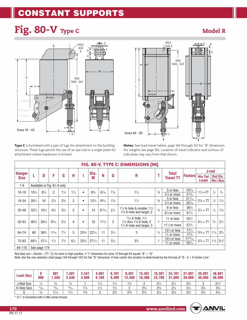
CONSTANT SUPPORTS
www.anvilintl.com170
Fig. 80-V Type C Model R
Load (lbs) 0 800
801 1,500
1,501 2,540
2,541 4,000
4,001 6,100
6,101 9,400
9,401 13,400
13,401 18,300
18,301 24,700
24,701 31,000
31,001 39,000
39,001 48,000
48,001 58,000
J-Rod Size 1⁄2 5⁄8 3⁄4 1 11⁄4 11⁄2 13⁄4 2 21⁄4 21⁄2 23⁄4 3 31⁄4*K-Hole Size 11⁄16 13⁄16 15⁄16 11⁄4 11⁄2 13⁄4 2 23⁄8 25⁄8 27⁄8 31⁄8 33⁄8 35⁄8
S 7⁄8 11⁄16 11⁄4 15⁄8 2 23⁄8 25⁄8 27⁄8 31⁄8 33⁄8 35⁄8 37⁄8 41⁄8* 31⁄4" is furnished with 4 UNC series thread.
FIG. 80-V, TYPE C: DIMENSIONS (IN)
Hanger Size L D F G H I Dia.
M N Q R T Total Travel TT Factors
J-rodMin Thd Length
Rod DIa.Min Max
1-9 Available in Fig. 81-H only
10-18 187⁄8 87⁄8 2 11⁄2 11⁄2 85⁄8 67⁄16 13⁄8 11⁄2 3⁄85 or less 195⁄16
13⁄4 +TT 1⁄2 3⁄451⁄2 or more 215⁄8
19-34 281⁄2 16 21⁄8 25⁄8 2 123⁄4 89⁄16 15⁄8 11⁄2 5⁄85 or less 311⁄16
23⁄8 + TT 1⁄2 11⁄451⁄2 or more 333⁄16
35-49 323⁄4 181⁄4 43⁄4 33⁄4 3 14 913⁄16 21⁄2 11⁄4 K-hole & smaller, 11⁄213⁄8 K-hole and larger, 2
3⁄46 or less 367⁄8
31⁄4 + TT 1⁄2 13⁄461⁄2 or more 411⁄2
50-63 467⁄8 281⁄8 85⁄16 57⁄8 4 18 111⁄4 315⁄16 K-hole, 11⁄2
11⁄8 thru 13⁄8 K-hole, 211⁄2 K-hole and larger, 3
111 or less 521⁄2
41⁄4 + TT 3⁄4 21⁄4111⁄2 or more 573⁄4
64-74 68 363⁄4 13⁄16 71⁄2 5 253⁄8 223⁄16 11 31⁄4 3 1⁄2101⁄2 or less 771⁄4
53⁄4 + TT 11⁄4 23⁄411 or more 773⁄8
75-83 691⁄2 371⁄4 11⁄2 71⁄2 61⁄4 253⁄8 273⁄16 11 31⁄4 33⁄4 1101⁄2 or less 7715⁄16
53⁄4 + TT 11⁄2 31⁄4*11 or more 781⁄16
84-110 See page 174
Note: See the size selection chart (page 164 through 167) for the “B” dimension. K hole center line location is determined by the formula of “B - G = K Center Line”.
Type C is furnished with a pair of lugs for attachment to the building structure. These lugs permit the use of an eye rod or a single plate for attachment where headroom is limited.
Notes: See load travel tables, page 164 through 167 for “B” dimension. For weights see page 182. Location of travel indicator and contour of side plate may vary from that shown.
R
H
T T
S
D
L
H Position
M Position
L Position
F
G
QB
JN
LC
RODTAKE - OUT
HM
L
HOLESIZE
K
M
R
HT T
S
M
L
L
D
F
I
B J
H
G
RODTAKE - OUT
M
N
HOLESIZE K
Sizes 10 - 63Sizes 64 - 83
PH-11.11
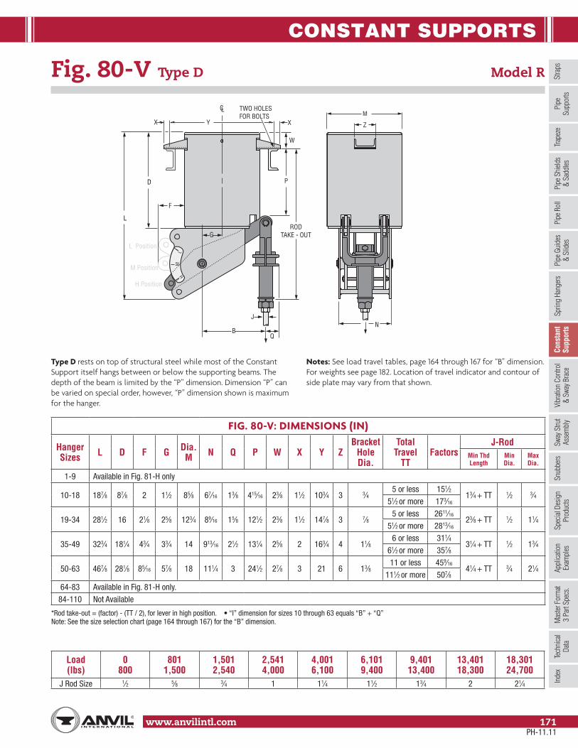
CONSTANT SUPPORTS
Stra
psSp
ring
Hang
ers
Cons
tant
Supp
orts
Vibr
ation
Con
trol
& Sw
ay B
race
Sway
Stru
tAs
sem
bly
Snub
bers
Appl
icatio
nEx
ampl
esSp
ecial
Des
ign
Prod
ucts
Trap
eze
Pipe
Rol
lPi
pe G
uide
s&
Slid
esPi
pe S
hield
s&
Sadd
lesPi
peSu
ppor
tsIn
dex
www.anvilintl.com 171
Tech
nica
lDa
taM
aster
For
mat
3 Pa
rt Sp
ecs.
Fig. 80-V Type D Model R
Load (lbs)
0 800
801 1,500
1,501 2,540
2,541 4,000
4,001 6,100
6,101 9,400
9,401 13,400
13,401 18,300
18,301 24,700
J Rod Size 1⁄2 5⁄8 3⁄4 1 11⁄4 11⁄2 13⁄4 2 21⁄4
FIG. 80-V: DIMENSIONS (IN)
Hanger Sizes L D F G Dia.
M N Q P W X Y ZBracket
Hole Dia.
Total Travel
TTFactors
J-RodMin Thd Length
Min Dia.
Max Dia.
1-9 Available in Fig. 81-H only
10-18 187⁄8 87⁄8 2 11⁄2 85⁄8 67⁄16 13⁄8 415⁄16 23⁄8 11⁄2 103⁄4 3 3⁄45 or less 151⁄2
13⁄4 + TT 1⁄2 3⁄451⁄2 or more 173⁄16
19-34 281⁄2 16 21⁄8 25⁄8 123⁄4 89⁄16 15⁄8 121⁄2 23⁄8 11⁄2 147⁄8 3 7⁄85 or less 2611⁄16
23⁄8 + TT 1⁄2 11⁄451⁄2 or more 2813⁄16
35-49 323⁄4 181⁄4 43⁄4 33⁄4 14 913⁄16 21⁄2 131⁄4 25⁄8 2 163⁄4 4 11⁄86 or less 311⁄4
31⁄4 + TT 1⁄2 13⁄461⁄2 or more 357⁄8
50-63 467⁄8 281⁄8 85⁄16 57⁄8 18 111⁄4 3 241⁄2 27⁄8 3 21 6 13⁄811 or less 459⁄16
41⁄4 + TT 3⁄4 21⁄4111⁄2 or more 507⁄8
64-83 Available in Fig. 81-H only.
84-110 Not Available
Note: See the size selection chart (page 164 through 167) for the “B” dimension.
Type D rests on top of structural steel while most of the Constant Support itself hangs between or below the supporting beams. The depth of the beam is limited by the “P” dimension. Dimension “P” can be varied on special order, however, “P” dimension shown is maximum for the hanger.
Notes: See load travel tables, page 164 through 167 for “B” dimension. For weights see page 182. Location of travel indicator and contour of side plate may vary from that shown.
D
L
H Position
M Position
L Position
F
G
QB
JN
LC
RODTAKE - OUT
HM
L
Z
W
P
XX Y
TWO HOLESFOR BOLTS M
PH-11.11

CONSTANT SUPPORTS
www.anvilintl.com172
Fig. 80-V Type E Model R
J-ROD SELECTION CHART
Load (lbs)
0 800
801 1,500
1,501 2,540
2,541 4,000
4,001 6,100
6,101 9,400
9,401 13,400
13,401 18,300
18,301 24,700
24,701 31,000
31,001 39,000
39,001 48,000
48,001 58,000
J Rod Size 1⁄2 5⁄8 3⁄4 1 11⁄4 11⁄2 13⁄4 2 21⁄4 21⁄2 23⁄4 3 31⁄4** 31⁄4" is furnished with 4 UNC series thread.
FIG. 80-V, TYPE E: DIMENSIONS (IN)
Hanger Size L C D F G I K Dia.
M X Y N Q Angle Size
Bracket Hole Dia.
Total Travel
TTFactors
J-RodMin
Thd LengthRod Dia
Min Max
1-9 Available in Fig. 81-H Only
10-18 187⁄8 11⁄2 87⁄8 2 11⁄2 45⁄16 85⁄8 5⁄8 815⁄16 67⁄16 13⁄8 11⁄2 x 2 x 1⁄4 3⁄45 or less 17⁄16
13⁄4 + TT 1⁄2 3⁄451⁄2 or more 33⁄4
19-34 281⁄2 13⁄16 16 21⁄8 25⁄8 611⁄16 123⁄4 5⁄8 113⁄16 89⁄16 15⁄8 11⁄2 x 21⁄2 x 1⁄4 3⁄45 or less 213⁄16
23⁄8 + TT 1⁄2 11⁄451⁄2 or more 415⁄16
35-49 323⁄4 17⁄8 181⁄4 43⁄4 33⁄4 85⁄16 14 13⁄16 135⁄16 913⁄16 21⁄2 3 x 2 x 3⁄8 7⁄86 or less 21⁄2
31⁄4 + TT 1⁄2 13⁄461⁄2 or more 71⁄8
50-63 467⁄8 33⁄4 281⁄8 85⁄16 57⁄8 1213⁄16 18 15⁄16 1411⁄16 111⁄4 3 3 x 3 x 3⁄813⁄8
11 or less 15⁄841⁄4 + TT 3⁄4 21⁄4
111⁄2 or more 7
64-74 62 3⁄8 353⁄4 3⁄8 71⁄2 253⁄8 153⁄4 223⁄16 19⁄16 1415⁄16 11 3 31⁄2 x 31⁄2 x 1⁄2101⁄2 or less 91⁄8
53⁄4 + TT 11⁄4 23⁄415⁄8
11 or more 91⁄4
75-83 621⁄2 51⁄4 353⁄4 11⁄2 71⁄2 253⁄8 255⁄8 273⁄16 13⁄4 151⁄2 11 3 4 x 4 x 3⁄8101⁄2 or less 83⁄4
53⁄4 + TT 11⁄2 31⁄415⁄8 11 or more 87⁄8
84-110 Not Available
Rod take-out = (factor) - (TT / 2), for lever in high position. Rod take-out is measured from the bottom of the supporting angles to the center of the load coupling site hole.
Type E rests on top flange of structural steel and the constant support itself is entirely above the supporting beams. If the rod takeout does not exceed the depth of the supporting steel and the rod coupling must extend below the steel, specify the depth of the supporting steel. Increase the rod take-out by the depth of the steel.
Notes: See load travel tables, page 164 through 167 for “B” dimension. For weights see page 182. Location of travel indicator and contour of side plate may vary from that shown.
D
L
HPosition
MPosition
LPosition
F
G
QB
LC
HM
L
CK
J
NY X
BOLTHOLES(4)
X
M
M
L
L
D
F
I
BC
J
H
G
K
M
L
L
D
F
I
B
CJ
H
G
K
Sizes 1 - 63 Sizes 64 - 74 Sizes 75 - 83
PH-11.11

CONSTANT SUPPORTS
Stra
psSp
ring
Hang
ers
Cons
tant
Supp
orts
Vibr
ation
Con
trol
& Sw
ay B
race
Sway
Stru
tAs
sem
bly
Snub
bers
Appl
icatio
nEx
ampl
esSp
ecial
Des
ign
Prod
ucts
Trap
eze
Pipe
Rol
lPi
pe G
uide
s&
Slid
esPi
pe S
hield
s&
Sadd
lesPi
peSu
ppor
tsIn
dex
www.anvilintl.com 173
Tech
nica
lDa
taM
aster
For
mat
3 Pa
rt Sp
ecs.
Fig. 80-V Type G Model R
Load (lbs)
0 800
801 1,500
1,501 2,540
2,541 4,000
4,001 6,100
6,101 9,400
9,401 13,400
13,401 18,300
18,301 24,700
J Rod Size 1⁄2 5⁄8 3⁄4 1 11⁄4 11⁄2 13⁄4 2 21⁄4
FIG. 80-V, TYPE G: DIMENSIONS (IN)
Hanger Size L D E F G Dia
M N P Q V YChannel
Size (lbs/ft)
C - CTotal Travel
TTFactors
J-RodMin
Thread Length
Min Rod. Dia.
Max Rod Dia.
1-9 Not available
10-18 187⁄8 87⁄8 1 2 11⁄2 85⁄8 67⁄16 29⁄16 31⁄2 513⁄16 315⁄16 4 @ 5.4 305 or less 1111⁄16
13⁄4 + TT 1⁄2 3⁄451⁄2 or more 14
19-34 281⁄2 16 11⁄4 21⁄8 25⁄8 123⁄4 89⁄16 39⁄16 4 9 61⁄8 6 @ 10.5 425 or less 1613⁄16
23⁄8 + TT 1⁄2 11⁄451⁄2 or more 183⁄4
35-49 323⁄4 181⁄4 11⁄2 43⁄4 33⁄4 14 913⁄16 37⁄16 51⁄2 103⁄4 8 10 @ 15.3 486 or less 191⁄4
31⁄4 + TT 1⁄2 13⁄461⁄2 or more 237⁄8
50-63 467⁄8 281⁄8 21⁄8 85⁄16 57⁄8 18 111⁄4 4 61⁄2 143⁄4 1015⁄16 12 @ 20.7 4811 or less 245⁄8
41⁄4 + TT 3⁄4 21⁄4111⁄2 or more 30
64-110 Not availableRod take-out = (factor) - (TT / 2), for lever in high position.Note: See the size selection chart (see page 164 through 167) for the “B” dimension.
Type G is a complete trapeze assembly. The hanger consists of two vertical type Constant Support units plus a pair of channels, back-to-back, welded at each end to the hanger casing. In sizing a Type G hanger, it must be remembered that each standard spring unit carries one-half of the total pipe load. Furthermore, the weights of the hanger itself must be considered as part of the overall load. Therefore, using one-half the total pipe load, select the required hanger size from the Load Travel Table and add one-half the weight of the size hanger selected to one-half the total pipe load. If the load now exceeds the maximum load at the required total travel for the hanger size selected, it is necessary to go to the next larger hanger. If the pipe line is designed so as not to be centered on the channel, one
spring of the trapeze will carry a heavier load than the other and care must be taken in sizing the individual hanger units. The center-to-center rod dimension must be specified when ordering. The minimum C-C dimension can be determined as follows:
B plus Q > Y: (O.D. of pipe covering) + 2Q. B plus Q < Y: (O.D. of pipe covering) + 2 (Y - B).
Note: If U-bolt is used to fasten pipe to channels, C-C of U-bolt tangents plus one washer plate width cannot be greater than C-C of the hanger rods minus 2 (V minus B). See load travel tables, page 164 through 167 for “B” dimension. For weights see page 182. Location of travel indicator and contour of side plate may vary from that shown.
HM
L
H
RODTAKE - OUT
C-C ROD DIMENSIONAS SPECIFIED
Q
JB
L F GV
M
D
P E
H
H Position
M Position
L Position
M
L
M
L
Note: For orientation of "N" Dimension, see Fig. 80-V Type D on page 171.
PH-11.11

CONSTANT SUPPORTS
www.anvilintl.com174
Fig. 80-V Types A, B and C Model R, Sizes 84 to 110
Load (lbs)
14,376 18,300
18,301 24,700
24,701 31,000
31,001 39,000
39,001 48,000
48,001 58,000
58,001 69,000
69,001 87,500
J & K-Rods 2 21⁄4 21⁄2 23⁄4 3 31⁄4* 31⁄2* 33⁄4*K-Hole 23⁄8 25⁄8 27⁄8 31⁄8 33⁄8 35⁄8 37⁄8 41⁄8
R 3 3 4 4 4 41⁄2 41⁄2 41⁄2S 27⁄8 31⁄8 33⁄8 35⁄8 37⁄8 41⁄8 43⁄8 45⁄8
T (Type B) 3⁄4 3⁄4 1 1 1 111⁄2 13⁄4
T (Type C) 11⁄4 11⁄4W 6 6 8 8 8 9 9 9
*31⁄4 and larger is furnished with 4 UNC series thread.
FIG. 80-V, TYPES A,B,C SIZES 84 TO 110: DIMENSIONS (IN)
Hanger Sizes L
CD
E GH M N P X
Total Travel
TT
Factor J - Rod
Type A & B
Type C
Type A & B
Type C
Type A & B
Type C
Type A
Type B & C
Min Thread Length
Rod Dia.
Min Max
84-94 783⁄4 16 15 493⁄4 4 41⁄2 11⁄2 1 6 24 101⁄2 3 1291⁄2 or less 453⁄4 543⁄4 10
2 33⁄410 or more 551⁄2 641⁄2 13
95-110 100 24 23 64 4 41⁄2 71⁄2 7 6 24 111⁄2 31⁄2 131⁄214 or less 511⁄8 605⁄8 12
21⁄2 33⁄4141⁄2 or more 601⁄8 695⁄8 15
*Rod take-out = (factor) - (.75 x TT), for Lever in high positionNote: See the size selection chart (page 164 through 167) for the “B” dimension.
Note: “B” Dimensions is a function of total travel (“G” + “B” should not be assumed as equal to “C” Dimension) Types A, B, and C sizes 84 through 110, for large loads and long travels, provide for basically the same methods of upper attachment as sizes 10 to 83 shown Type A on page 168, Type B page 169 and Type C see page 170.
Notes: See load travel tables, page 164 through 167 for “B” dimension. For weights see page 182.
L
D
J
RODTAKEOUT
X
G
B
P
EC
K
N
M
K HOLESIZE
W
TT
S
C
T
H
E
R R
KHOLESIZE
W
C E
RODTAKEOUT
RODTAKEOUT
H
TYPE B
TYPE A
TYPE C
PH-11.11
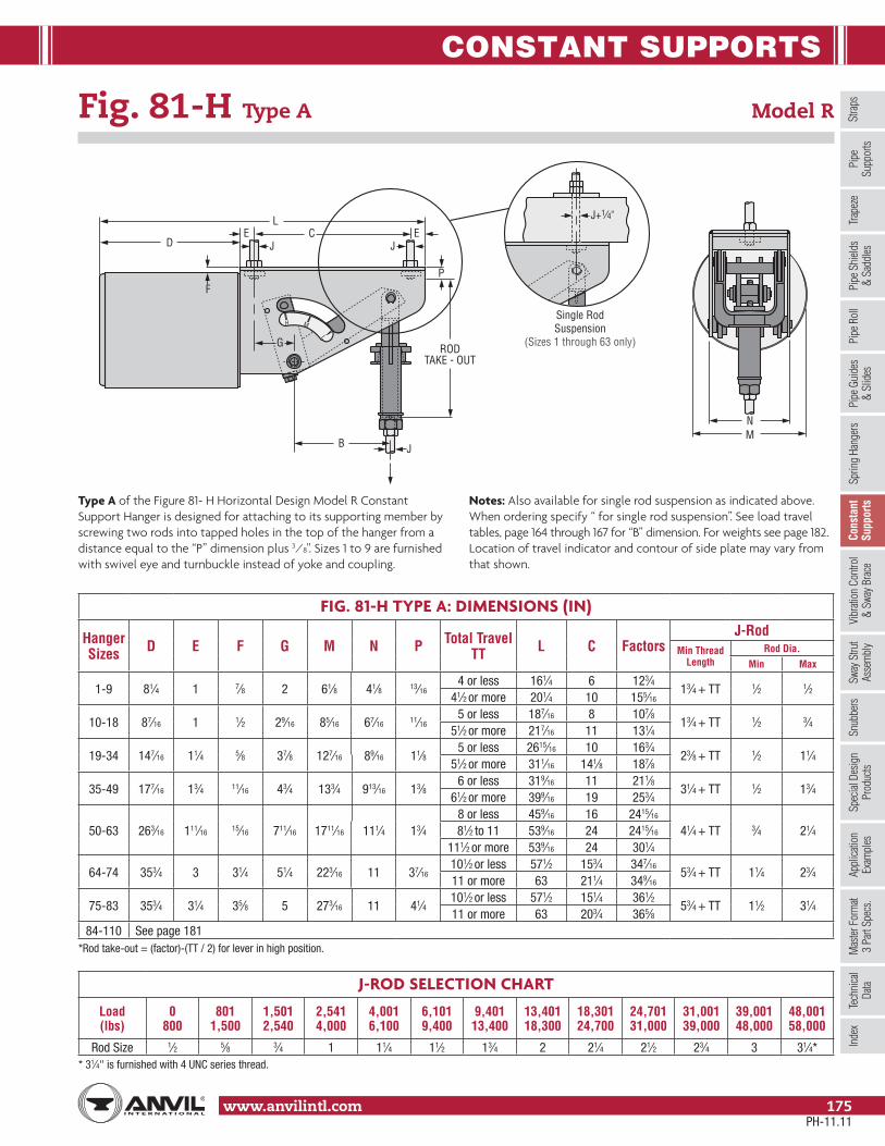
CONSTANT SUPPORTS
Stra
psSp
ring
Hang
ers
Cons
tant
Supp
orts
Vibr
ation
Con
trol
& Sw
ay B
race
Sway
Stru
tAs
sem
bly
Snub
bers
Appl
icatio
nEx
ampl
esSp
ecial
Des
ign
Prod
ucts
Trap
eze
Pipe
Rol
lPi
pe G
uide
s&
Slid
esPi
pe S
hield
s&
Sadd
lesPi
peSu
ppor
tsIn
dex
www.anvilintl.com 175
Tech
nica
lDa
taM
aster
For
mat
3 Pa
rt Sp
ecs.
Fig. 81-H Type A Model R
J-ROD SELECTION CHART
Load (lbs)
0 800
801 1,500
1,501 2,540
2,541 4,000
4,001 6,100
6,101 9,400
9,401 13,400
13,401 18,300
18,301 24,700
24,701 31,000
31,001 39,000
39,001 48,000
48,001 58,000
Rod Size 1⁄2 5⁄8 3⁄4 1 11⁄4 11⁄2 13⁄4 2 21⁄4 21⁄2 23⁄4 3 31⁄4** 31⁄4" is furnished with 4 UNC series thread.
FIG. 81-H TYPE A: DIMENSIONS (IN)
Hanger Sizes D E F G M N P Total Travel
TT L C FactorsJ-Rod
Min Thread Length
Rod Dia.Min Max
1-9 81⁄4 1 7⁄8 2 61⁄8 41⁄8 13⁄164 or less 161⁄4 6 123⁄4
13⁄4 + TT 1⁄2 1⁄241⁄2 or more 201⁄4 10 155⁄16
10-18 87⁄16 1 1⁄2 29⁄16 85⁄16 67⁄16 11⁄165 or less 187⁄16 8 107⁄8
13⁄4 + TT 1⁄2 3⁄451⁄2 or more 217⁄16 11 131⁄4
19-34 147⁄16 11⁄4 5⁄8 37⁄8 127⁄16 89⁄16 11⁄85 or less 2615⁄16 10 163⁄4
23⁄8 + TT 1⁄2 11⁄451⁄2 or more 311⁄16 141⁄8 187⁄8
35-49 177⁄16 13⁄4 11⁄16 43⁄4 133⁄4 913⁄16 13⁄86 or less 319⁄16 11 211⁄8
31⁄4 + TT 1⁄2 13⁄461⁄2 or more 399⁄16 19 253⁄4
50-63 263⁄16 111⁄16 15⁄16 711⁄16 1711⁄16 111⁄4 13⁄48 or less 459⁄16 16 2415⁄16
41⁄4 + TT 3⁄4 21⁄481⁄2 to 11 539⁄16 24 2415⁄16
111⁄2 or more 539⁄16 24 301⁄4
64-74 353⁄4 3 31⁄4 51⁄4 223⁄16 11 37⁄16101⁄2 or less 571⁄2 153⁄4 347⁄16
53⁄4 + TT 11⁄4 23⁄411 or more 63 211⁄4 349⁄16
75-83 353⁄4 31⁄4 35⁄8 5 273⁄16 11 41⁄4101⁄2 or less 571⁄2 151⁄4 361⁄2
53⁄4 + TT 11⁄2 31⁄411 or more 63 203⁄4 365⁄8
84-110 See page 181*Rod take-out = (factor)-(TT / 2) for lever in high position.
Type A of the Figure 81- H Horizontal Design Model R Constant Support Hanger is designed for attaching to its supporting member by screwing two rods into tapped holes in the top of the hanger from a distance equal to the “P” dimension plus 3⁄8". Sizes 1 to 9 are furnished with swivel eye and turnbuckle instead of yoke and coupling.
Notes: Also available for single rod suspension as indicated above. When ordering specify “ for single rod suspension”. See load travel tables, page 164 through 167 for “B” dimension. For weights see page 182. Location of travel indicator and contour of side plate may vary from that shown.
LC
D
BMN
RODTAKE - OUT
Single RodSuspension
(Sizes 1 through 63 only)
F
G
EEJJ
P
J
J+1⁄4"
H M
L
PH-11.11

CONSTANT SUPPORTS
www.anvilintl.com176
Fig. 81-H Type B Model R
J-ROD AND K-HOLE SELECTION CHART
Load (lbs)
0 800
801 1,500
1,501 2,540
2,541 4,000
4,001 6,100
6,101 9,400
9,401 13,400
13,401 18,300
18,301 24,700
24,701 31,000
31,001 39,000
39,001 48,000
48,001 58,000
J-rod 1⁄2 5⁄8 3⁄4 1 11⁄4 11⁄2 13⁄4 2 21⁄4 21⁄2 23⁄4 3 31⁄4**K-Hole Size 11⁄16 13⁄16 15⁄16 11⁄4 11⁄2 13⁄4 2 23⁄8 25⁄8 27⁄8 31⁄8 33⁄8 35⁄8
R 11⁄4 11⁄4 11⁄4 11⁄2 2 21⁄2 21⁄2 3 3 4 4 4 41⁄2T 1⁄4* 1⁄4* 3⁄8 1⁄2 5⁄8 3⁄4 3⁄4 3⁄4 3⁄4 1 1 1 1W 21⁄2 21⁄2 21⁄2 3 4 5 5 6 6 8 8 8 9
* 3⁄8" for single rod suspension ** 31⁄4" is furnished with 4 UNC series thread.
FIG. 81-H TYPE B: DIMENSIONS (IN)
Hanger Sizes D E F G H M N Total Travel
TT L C FactorsJ-Rod
Min Thd Length
Rod Dia.Min Max
1 - 9 81⁄4 11⁄4 7⁄8 13⁄4 11⁄2 61⁄8 41⁄84 or less 161⁄4 51⁄2 145⁄8
13⁄4 + TT 1⁄2 1⁄241⁄2 or more 201⁄4 91⁄2 173⁄16
10 - 18 87⁄16 11⁄4 1⁄2 25⁄16 11⁄2 85⁄16 67⁄165 or less 187⁄16 71⁄2 131⁄16
13⁄4 + TT 1⁄2 3⁄451⁄2 or more 217⁄16 101⁄2 157⁄16
19 - 34 147⁄16 13⁄8 5⁄8 33⁄4 2 127⁄16 89⁄165 or less 2615⁄16 93⁄4 197⁄8
23⁄8 + TT 1⁄2 11⁄451⁄2 or more 311⁄16 137⁄8 22
35 - 49 1613⁄16 2 11⁄16 41⁄2 3 133⁄4 913⁄166 or less 319⁄16 101⁄2 255⁄8
31⁄4 + TT 1⁄2 13⁄461⁄2 or more 399⁄16 181⁄2 301⁄8
50 - 63 263⁄16 3 15⁄16 63⁄8 4 173⁄8 111⁄48 or less 459⁄16 133⁄8 3011⁄16
41⁄4 + TT 3⁄4 21⁄481⁄2 to 11 539⁄16 213⁄8 3011⁄16
111⁄2 or more 539⁄16 213⁄8 36
64 - 74 353⁄4 31⁄4 31⁄4 5 41⁄2 223⁄16 11101⁄2 or less 571⁄2 151⁄4 423⁄8
53⁄4 + TT 11⁄4 23⁄411 or more 63 203⁄4 421⁄2
75 - 83 353⁄4 31⁄2 35⁄8 43⁄4 5 273⁄16 11101⁄2 or less 571⁄2 143⁄4 453⁄4
53⁄4 + TT 11⁄2 31⁄4**11 or more 63 201⁄4 457⁄8
84 - 110 See page 181* Rod take-out = (factor) - (TT / 2), for lever in high position.
Type B is furnished with two lugs – one at each end of the hanger frame. These lugs permit use of Fig. 66 welded beam attachments, clevises or angle clips for attachment where headroom is limited. Sizes 1 to 9 are furnished with swivel eye and turnbuckle instead of yoke and coupling.
Notes: Also available for single rod suspension as indicated above. When ordering specify “for single rod suspension.” See load travel tables, page 164 through 167 for “B” dimension. For weights see page 182. Location of travel indicator and contour of side plate may vary form that shown.
BMN
RODTAKE - OUT
G
J
H M
L
LC
D
E E
T
HOLE SIZE K
H
F
R
W
2WW
R
H
W⁄2W⁄2
Single RodSuspension
(Sizes 1 through 63 only)
PH-11.11

CONSTANT SUPPORTS
Stra
psSp
ring
Hang
ers
Cons
tant
Supp
orts
Vibr
ation
Con
trol
& Sw
ay B
race
Sway
Stru
tAs
sem
bly
Snub
bers
Appl
icatio
nEx
ampl
esSp
ecial
Des
ign
Prod
ucts
Trap
eze
Pipe
Rol
lPi
pe G
uide
s&
Slid
esPi
pe S
hield
s&
Sadd
lesPi
peSu
ppor
tsIn
dex
www.anvilintl.com 177
Tech
nica
lDa
taM
aster
For
mat
3 Pa
rt Sp
ecs.
Fig. 81-H Type C Model R
J-ROD AND K-HOLE SELECTION CHART
Load (lbs)
0 800
801 1,500
1,501 2,540
2,541 4,000
4,001 6,100
6,101 9,400
9,401 13,400
13,401 18,300
18,301 24,700
24,701 31,000
31,001 39,000
39,001 48,000
48,001 58,000
J-Rod 1⁄2 5⁄8 3⁄4 1 11⁄4 11⁄2 13⁄4 2 21⁄4 21⁄2 23⁄4 3 31⁄4**K-Hole Size 11⁄16 13⁄16 15⁄16 11⁄4 11⁄2 13⁄4 2 23⁄8 25⁄8 27⁄8 31⁄8 33⁄8 35⁄8
R 11⁄4 11⁄4 11⁄4 11⁄2 2 21⁄2 21⁄2 3 3 4 4 4 41⁄2S 7⁄8 11⁄16 11⁄4 15⁄8 2 23⁄8 25⁄8 27⁄8 31⁄8 33⁄8 35⁄8 37⁄8 41⁄8T 1⁄4* 1⁄4* 3⁄8 1⁄2 5⁄8 3⁄4 3⁄4 3⁄4 3⁄4 1 1 1 1W 21⁄2 21⁄2 21⁄2 3 4 5 5 6 6 8 8 8 9
* 3⁄8" for single rod suspension ** 31⁄4" is furnished with 4 UNC series thread.
FIG. 81-H TYPE C: DIMENSIONS (INCHES)
Hanger Sizes D E F G H M N Total Travel
TT L C FactorsJ-Rod
Min Thd Length
Rod Dia.Min Max
1 - 9 81⁄4 11⁄4 7⁄8 13⁄4 11⁄2 61⁄8 41⁄84 or less 161⁄4 51⁄2 145⁄8
13⁄4 + TT 1⁄2 1⁄241⁄2 or more 201⁄4 91⁄2 173⁄16
10 - 18 87⁄16 11⁄4 1⁄2 25⁄16 11⁄2 85⁄16 67⁄165 or less 187⁄16 71⁄2 131⁄16
13⁄4 + TT 1⁄2 3⁄451⁄2 or more 217⁄16 101⁄2 157⁄16
19 - 34 147⁄16 2 5⁄8 31⁄8 2 127⁄16 89⁄165 or less 2615⁄16 81⁄2 197⁄8
23⁄8 + TT 1⁄2 11⁄451⁄2 or more 311⁄16 125⁄8 22
35 - 49 171⁄16 21⁄2 11⁄16 4 3 133⁄4 913⁄166 or less 319⁄16 91⁄2 255⁄8
31⁄4 + TT 1⁄2 13⁄461⁄2 or more 399⁄16 171⁄2 301⁄8
50 - 63 263⁄16 3 15⁄16 63⁄8 4 1711⁄16 111⁄48 or less 459⁄16 133⁄8 3011⁄16
41⁄4 + TT 3⁄4 21⁄481⁄2 to 11 539⁄16 213⁄8 3011⁄16
111⁄2 or more 539⁄16 213⁄8 36
64 - 74 353⁄4 4 31⁄4 41⁄4 41⁄2 223⁄16 11101⁄2 or less 571⁄2 133⁄4 423⁄8
53⁄4 + TT 11⁄4 23⁄411 or more 63 191⁄4 421⁄2
75 - 83 353⁄4 41⁄2 35⁄8 33⁄4 5 273⁄16 11101⁄2 or less 571⁄2 123⁄4 453⁄4
53⁄4 + TT 11⁄2 31⁄411 or more 63 181⁄4 453⁄4
84 - 110 See page 181* Rod take-out = (factor) - (TT / 2), for lever in high position.
Type C is furnished with two pair of lugs, one pair of lugs at each of the hanger frame. These lugs permit the use of two eye rods or two single plates for attachment where headroom is limited. Sizes 1 to 9 are furnished with swivel eye and turnbuckle instead of yoke and coupling.
Notes: Also available for single rod suspension as indicated above. When ordering specify “for single rod suspension.” See load travel tables, page 164 through 167 for “B” dimension. For weights see page 182. Location of travel indicator and contour of side plate may vary from that shown.
T T
L
C
D
E EW
HOLESIZE K
H
R 2W
WR
H
W/2
S
BM
N
RODTAKE - OUT
G
J
H M
L
F
Single RodSuspension
(Sizes 1 through 63 only)
PH-11.11

CONSTANT SUPPORTS
www.anvilintl.com178
Type D may be bolted directly under steel. Sizes 1 to 9 are furnished with swivel eye and turnbuckle instead of yoke and coupling.
Notes: See load travel tables, page 164 through 167 for “B” dimension. For weights see page 182. Location of travel indicator and contour of side plate may vary from that shown.
Fig. 81-H Type D Model R
J-ROD SELECTION CHART
Load (lbs)
0 800
801 1,500
1,501 2,540
2,541 4,000
4,001 6,100
6,101 9,400
9,401 13,400
13,401 18,300
18,301 24,700
24,701 31,000
31,001 39,000
39,001 48,000
48,001 58,000
J Rod Size 1⁄2 5⁄8 3⁄4 1 11⁄4 11⁄2 13⁄4 2 21⁄4 21⁄2 23⁄4 3 31⁄4**31⁄4" is furnished with 4 UNC series thread.
FIG. 81-H TYPE D: DIMENSIONS (INCHES)
Hanger Sizes D E F G M N X Y Angle
Size
Bracket Hole Dia.
Total Travel TT L C Factors
J-RodMin Thd Length
Rod Dia.Min Max
1 - 9 81⁄4 1 7⁄8 2 61⁄8 41⁄8 3⁄4 55⁄8 2 x 2 x 1⁄4 9⁄164 or less 161⁄4 6 133⁄8
13⁄4 + TT 1⁄2 1⁄241⁄2 or more 201⁄4 10 1515⁄16
10 - 18 87⁄16 31⁄4 1⁄2 29⁄16 85⁄16 67⁄16 7⁄8 81⁄16 11⁄2 x 11⁄2 x 1⁄4 3⁄45 or less 187⁄16 31⁄2 1113⁄16
13⁄4 + TT 1⁄2 3⁄451⁄2 or more 217⁄16 6 143⁄16
19 - 34 147⁄16 11⁄2 5⁄8 35⁄8 127⁄16 89⁄16 11⁄8 115⁄16 3 x 31⁄2 x 1⁄4 3⁄45 or less 2615⁄16 91⁄2 173⁄4
23⁄8 + TT 1⁄2 11⁄451⁄2 or more 311⁄16 135⁄8 197⁄8
35 - 49 171⁄16 2 11⁄16 41⁄2 133⁄4 913⁄16 13⁄8 13 3 x 4 x 3⁄8 7⁄86 or less 319⁄16 101⁄2 2013⁄16
31⁄4 + TT 1⁄2 13⁄461⁄2 or more 399⁄16 181⁄2 257⁄16
50 - 63 263⁄16 2 15⁄16 73⁄8 1711⁄16 111⁄4 15⁄8 145⁄8 4 x 4 x 3⁄8 13⁄8
8 or less 459⁄16 153⁄8 271⁄16
41⁄4 + TT 3⁄4 21⁄481⁄2 to 11 539⁄16 233⁄8 271⁄16
11 or more 539⁄16 233⁄8 323⁄8
64 - 74 353⁄4 3 31⁄4 51⁄4 223⁄16 11 2 15 4 x 6 x 1⁄2 15⁄8101⁄2 or less 571⁄2 153⁄4 383⁄8
53⁄4 + TT 11⁄4 23⁄411 or more 63 211⁄4 381⁄2
75 - 83 353⁄4 3 35⁄8 43⁄4 273⁄16 11 2 15 4 x 6 x 1⁄2 15⁄8101⁄2 or less 571⁄2 153⁄4 411⁄4
53⁄4 + TT 11⁄2 31⁄411 or more 63 211⁄4 413⁄8
84 - 110 Not available
* Rod take-out = factor - (TT / 2), for lever in high position.
LC
DE E
B
MN
RODTAKE - OUT
G
J
H M
L
FOUR HOLESFOR BOLTS
XY
F
X
PH-11.11

CONSTANT SUPPORTS
Stra
psSp
ring
Hang
ers
Cons
tant
Supp
orts
Vibr
ation
Con
trol
& Sw
ay B
race
Sway
Stru
tAs
sem
bly
Snub
bers
Appl
icatio
nEx
ampl
esSp
ecial
Des
ign
Prod
ucts
Trap
eze
Pipe
Rol
lPi
pe G
uide
s&
Slid
esPi
pe S
hield
s&
Sadd
lesPi
peSu
ppor
tsIn
dex
www.anvilintl.com 179
Tech
nica
lDa
taM
aster
For
mat
3 Pa
rt Sp
ecs.
Type E incorporates two brackets as part of its frame, permitting the bolting of the constant support to the top of structural steel. Sizes 1 to 9 are furnished with swivel eye and turnbuckle instead of yoke and coupling. If rod take-out does not exceed the depth of the sup-porting steel and rod coupling is required to extend below the steel,
specify the depth of the supporting steel. Increase rod take-out by the depth of the steel. Notes: See load travel tables, page 164 through 167 for “B” dimension. For weights see page 182. Location of travel indicator and contour of side plate may vary from that shown.
Fig. 81-H Type E Model R
J-ROD SELECTION CHART
Load (lbs)
0 800
801 1,500
1,501 2,540
2,541 4,000
4,001 6,100
6,101 9,400
9,401 13,400
13,401 18,300
18,301 24,700
24,701 31,000
31,001 39,000
39,001 48,000
48,001 58,000
J Rod Size 1⁄2 5⁄8 3⁄4 1 11⁄4 11⁄2 13⁄4 2 21⁄4 21⁄2 23⁄4 3 31⁄4**31⁄4" is furnished with 4 UNC series thread.
FIG. 81-H TYPE E: DIMENSIONS (IN)
Hanger Sizes D F G M N P X Y Angle Size
Bkt. Hole Dia.
Total Travel TT L K Factors
J-RodMin Thd Length
Rod Dia.Min Max
1 - 9 81⁄4 11⁄4 2 61⁄8 41⁄8 81⁄2 5⁄8 515⁄16 11⁄2 x 11⁄2 x 1⁄4 9⁄164 or less 161⁄4 6 51⁄8
13⁄4 + TT 1⁄2 1⁄241⁄2 or more 201⁄4 10 711⁄16
10 - 18 87⁄16 1 21⁄16 85⁄16 67⁄16 117⁄16 5⁄8 815⁄16 11⁄2 x 2 x 1⁄4 3⁄45 or less 187⁄16 71⁄2 13⁄4
13⁄4 + TT 1⁄2 3⁄451⁄2 or more 217⁄16 71⁄2 41⁄16
19 - 34 147⁄16 5⁄8 35⁄8 127⁄16 89⁄16 151⁄8 5⁄8 113⁄16 11⁄2 x 21⁄2 x 1⁄4 3⁄45 or less 2615⁄16 10 33⁄8
23⁄8 + TT 1⁄2 11⁄451⁄2 or more 311⁄16 10 51⁄2
35 - 49 171⁄16 11⁄16 41⁄2 133⁄4 913⁄16 195⁄8 13⁄16 135⁄16 3 x 2 x 3⁄8 7⁄86 or less 319⁄16 115⁄8 47⁄8
31⁄4 + TT 1⁄2 13⁄461⁄2 or more 399⁄16 115⁄8 91⁄2
50 - 63 263⁄16 15⁄16 73⁄8 1711⁄16 111⁄4 193⁄4 15⁄16 1411⁄16 3 x 3 x 3⁄8 13⁄88 or less 459⁄16 153⁄8 67⁄8
41⁄4 + TT 3⁄4 21⁄481⁄2 to 11 539⁄16 233⁄8 67⁄8111⁄2 or more 539⁄16 233⁄8 121⁄4
64 - 74 353⁄4 31⁄4 51⁄4 223⁄16 11 267⁄8 19⁄16 1415⁄16 31⁄2 x 31⁄2 x 1⁄2 15⁄8101⁄2 or less 571⁄2 171⁄2 111⁄8
53⁄4 + TT 11⁄4 23⁄411 or more 63 23 111⁄4
75 - 83 353⁄4 35⁄8 43⁄4 273⁄16 11 317⁄8 19⁄16 1415⁄16 31⁄2 x 31⁄2 x 1⁄2 15⁄8101⁄2 or less 571⁄2 171⁄2 9
53⁄4 + TT 11⁄2 31⁄411 or more 63 23 91⁄8
84 - 110 Refer to page 181* Rod take-out = (factor) - (TT / 2), for lever in high position.
K
N
RODTAKE - OUT
FOUR HOLESFOR BOLTS
G
LD
B J
H M
L
F
Y
PM
XX
PH-11.11
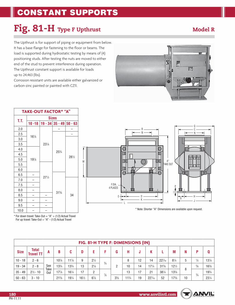
CONSTANT SUPPORTS
www.anvilintl.com180
Fig. 81-H Type F Upthrust Model R
The Upthrust is for support of piping or equipment from below. It has a base flange for fastening to the floor or beams. The load is supported during hydrostatic testing by means of (4) positioning studs. After testing the nuts are moved to either end of the stud to prevent interference during operation. The Upthrust constant support is available for loads up to 24,463 (lbs). Corrosion resistant units are available either galvanized or carbon-zinc painted or painted with CZ11.
FIG. 81-H TYPE F: DIMENSIONS (IN)
Size Total Travel TT A B C D E F G H J K L M N P Q
10 - 18 2 - 6
See Take Out
107⁄8 117⁄8 9 21⁄23⁄4
2
8 12 14 227⁄16 81⁄4 5 1⁄2 137⁄8
19 - 34 2 - 8 133⁄4 133⁄4 13 21⁄8 10 14 171⁄4 315⁄8 121⁄28
5⁄8 163⁄8
35 - 49 21⁄2 - 10 177⁄8 161⁄4 17 27⁄8
13 17 21 381⁄4 135⁄83⁄4
193⁄4
50 - 63 3 - 10 215⁄8 191⁄4 161⁄2 67⁄8 35⁄8 113⁄4 19 227⁄16 52 173⁄8 10 231⁄4
TAKE-OUT FACTOR* “A”
T.T.Sizes
10 -18 19 - 34 35 - 49 50 - 632.0
161⁄8
231⁄8
– –
2.5
253⁄4
–
3.0
281⁄2
3.5
4.0
197⁄8
4.5
5.0
5.5
271⁄2
6.0
6.5 –
315⁄8
7.0 –
34
7.5 –
8.0 –
8.5 – –
9.0 – –
9.5 – –
10.0 – –
* For down travel: Take-Out = “A” + (1/2) Actual Travel For up travel: Take-Out = “A” - (1/2) Actual Travel
M
BN
E DK
L
CQ
G
P
HJ
F DIA.4 PLACES
A*TAKE OUT
N
* Note: Shorter "A" Dimensions are available upon request.
PH-11.11

CONSTANT SUPPORTS
Stra
psSp
ring
Hang
ers
Cons
tant
Supp
orts
Vibr
ation
Con
trol
& Sw
ay B
race
Sway
Stru
tAs
sem
bly
Snub
bers
Appl
icatio
nEx
ampl
esSp
ecial
Des
ign
Prod
ucts
Trap
eze
Pipe
Rol
lPi
pe G
uide
s&
Slid
esPi
pe S
hield
s&
Sadd
lesPi
peSu
ppor
tsIn
dex
www.anvilintl.com 181
Tech
nica
lDa
taM
aster
For
mat
3 Pa
rt Sp
ecs.
NM
TYPE A
J
B
RODTAKEOUT
G
D
L
C
K P K
E
P
K HOLESIZE
TYPE B
W
C
T
HR
E
RODTAKE OUT
RODTAKE OUT
S
T T
C
H
WR
E
K HOLE SIZE
G BKZ
3"
TYPE E
X
QY
ROD TAKE OUT
F FOURHOLES
1/2"
TYPE C
MN
Fig. 81-H, Types A, B, C and E Model R, Sizes 84 to 110
Types A, B, and C sizes 84 to 110, for large loads and long
travels, provide for basically the same methods of upper
attachment as sizes 1 through 83 shown on page 175 through 177.
Type E is designed for bolting to the top of structural steel,
see page 179 for sizes 1 to 83.
Notes: See load travel tables, page 164 through 167 for “B”
dimension. For weights see page 182.
Load (lbs)
14,376 18,300
18,301 24,700
24,701 31,000
31,001 39,000
39,001 48,000
48,001 58,000
58,001 69,000
69,001 87,500
J & K-Rods 2 21⁄4 21⁄2 23⁄4 3 31⁄4* 31⁄2* 33⁄4*K-Hole 23⁄8 25⁄8 27⁄8 31⁄8 33⁄8 35⁄8 37⁄8 41⁄8
R 3 3 4 4 4 41⁄2 41⁄2 41⁄2S 27⁄8 31⁄8 33⁄8 35⁄8 37⁄8 41⁄8 43⁄8 45⁄8
T (Type B) 3⁄4 3⁄4 1 1 1 111⁄2 13⁄4
T (Type C) 11⁄4 11⁄4W 6 6 8 8 8 9 9 9
*31⁄4 and larger is furnished with 4 UNC series thread.
FIG. 81-H, TYPES A, B, C AND E: DIMENSIONS (IN)
Hanger Size L
CD
EF
GH K M N P Q X Y Z
Total Travel
TT
Factors J-Rod
Type A&B
Type C
Type A&B
Type C
Type A&B &C
Type E
Type A
Type B&C
Type E
Min Thd Lgth
Rod Dia.
Min Max
84-94 763⁄4 28 271⁄2 493⁄4 4 41⁄2 11⁄8 14 6 6 21 24 101⁄2 3 16 34 13 27
91⁄2 or less 453⁄4 543⁄4 215⁄8 10
2 33⁄410 or more 551⁄2 641⁄2 313⁄8 13
95-110 100 49 481⁄2 64 4 41⁄2 13⁄8 283⁄4 83⁄4 6 30 24 111⁄2 31⁄2 17 37 141⁄2 36
14 or less 561⁄2 66 175⁄8 12
21⁄2 33⁄4141⁄2
or more 653⁄8 747⁄8 265⁄8 15
* Rod take-out = (factor) - (0.75 x TT), for lever in high position.
PH-11.11
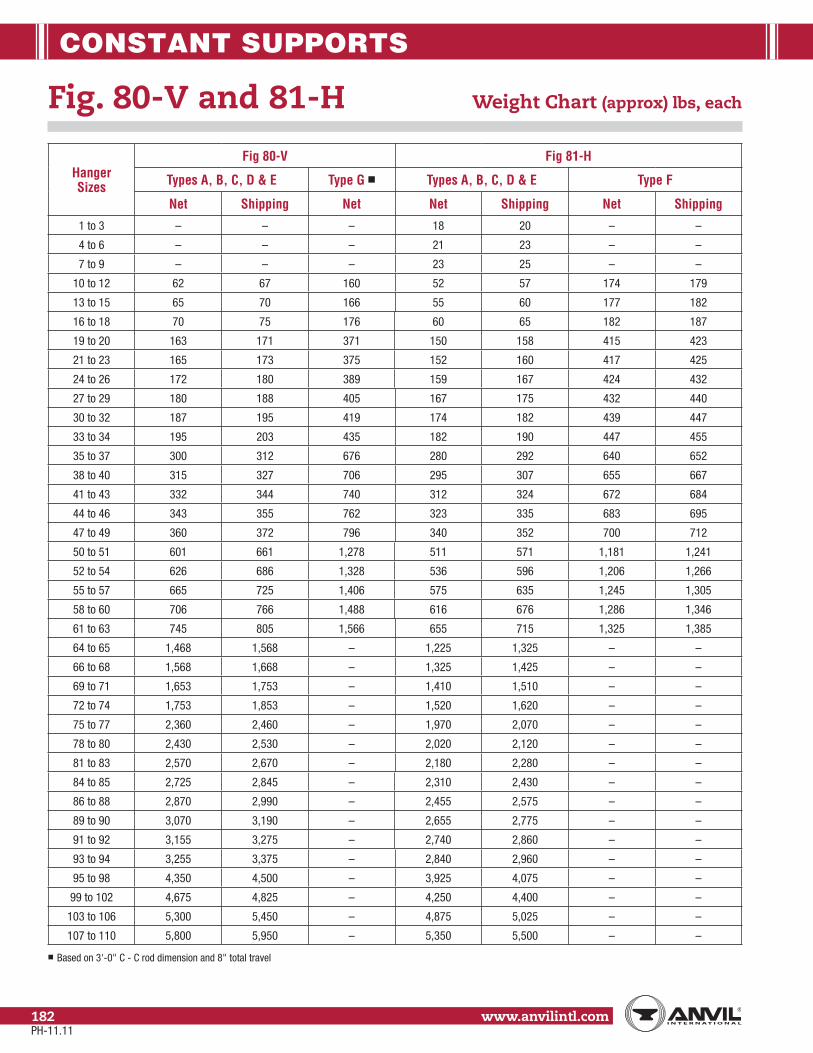
CONSTANT SUPPORTS
www.anvilintl.com182
Hanger Sizes
Fig 80-V Fig 81-H
Types A, B, C, D & E Type G ■ Types A, B, C, D & E Type F
Net Shipping Net Net Shipping Net Shipping
1 to 3 – – – 18 20 – –
4 to 6 – – – 21 23 – –
7 to 9 – – – 23 25 – –
10 to 12 62 67 160 52 57 174 179
13 to 15 65 70 166 55 60 177 182
16 to 18 70 75 176 60 65 182 187
19 to 20 163 171 371 150 158 415 423
21 to 23 165 173 375 152 160 417 425
24 to 26 172 180 389 159 167 424 432
27 to 29 180 188 405 167 175 432 440
30 to 32 187 195 419 174 182 439 447
33 to 34 195 203 435 182 190 447 455
35 to 37 300 312 676 280 292 640 652
38 to 40 315 327 706 295 307 655 667
41 to 43 332 344 740 312 324 672 684
44 to 46 343 355 762 323 335 683 695
47 to 49 360 372 796 340 352 700 712
50 to 51 601 661 1,278 511 571 1,181 1,241
52 to 54 626 686 1,328 536 596 1,206 1,266
55 to 57 665 725 1,406 575 635 1,245 1,305
58 to 60 706 766 1,488 616 676 1,286 1,346
61 to 63 745 805 1,566 655 715 1,325 1,385
64 to 65 1,468 1,568 – 1,225 1,325 – –
66 to 68 1,568 1,668 – 1,325 1,425 – –
69 to 71 1,653 1,753 – 1,410 1,510 – –
72 to 74 1,753 1,853 – 1,520 1,620 – –
75 to 77 2,360 2,460 – 1,970 2,070 – –
78 to 80 2,430 2,530 – 2,020 2,120 – –
81 to 83 2,570 2,670 – 2,180 2,280 – –
84 to 85 2,725 2,845 – 2,310 2,430 – –
86 to 88 2,870 2,990 – 2,455 2,575 – –
89 to 90 3,070 3,190 – 2,655 2,775 – –
91 to 92 3,155 3,275 – 2,740 2,860 – –
93 to 94 3,255 3,375 – 2,840 2,960 – –
95 to 98 4,350 4,500 – 3,925 4,075 – –
99 to 102 4,675 4,825 – 4,250 4,400 – –
103 to 106 5,300 5,450 – 4,875 5,025 – –
107 to 110 5,800 5,950 – 5,350 5,500 – –
■
Fig. 80-V and 81-H Weight Chart (approx) lbs, each
PH-11.11

CONSTANT SUPPORTS
Stra
psSp
ring
Hang
ers
Cons
tant
Supp
orts
Vibr
ation
Con
trol
& Sw
ay B
race
Sway
Stru
tAs
sem
bly
Snub
bers
Appl
icatio
nEx
ampl
esSp
ecial
Des
ign
Prod
ucts
Trap
eze
Pipe
Rol
lPi
pe G
uide
s&
Slid
esPi
pe S
hield
s&
Sadd
lesPi
peSu
ppor
tsIn
dex
www.anvilintl.com 183
Tech
nica
lDa
taM
aster
For
mat
3 Pa
rt Sp
ecs.
Constant Support Check List for Requesting a Quote or Ordering
Anvil International
Precision Park
160 Frenchtown Rd.
North Kingstown, RI 02852
For technical information regarding
Constant Supports Call or Fax:
Fax Number: (401) 886-3056
Phone Number: (401) 886-3025
Page ___ of ____
Finish: Standard Primer: __________ Galvanized: __________ Special Coating: _______________
Quantity: _______________
Figure No.: Options a re: ❏ 80-V, ❏ 81-H or: ❏ C-80-V, ❏ C-81-H
Size: Options are: #1 through #110 (Size #1 through #9 available in 81-H only) ____________________
Type: Options are: A through G* (Type F Upthrust available in 81-H only, Type G available in 80-V only) __________
Actual Travel (AT): _______________ (inches)
Total Travel (TT)**: _______________(inches)
Direction of Travel: _______________ + (up) or – (down)
Load: _______________ (lbs)
“J” Dimension (rod diameter): _______________ (inches) (Not required for Type F)
Mark Number: _______________ (If required)
Travel Stops: Are always Included
Lifting Lugs: Yes: _________ No: __________ Available on sizes 10 and larger.
Notes: * Type G Constants must also include the C-to-C dimension & the load per spring. ** Total Travel = Actual travel + 1” or 20% whichever is greater rounded up to the next one half inch
increment.
PH-11.11
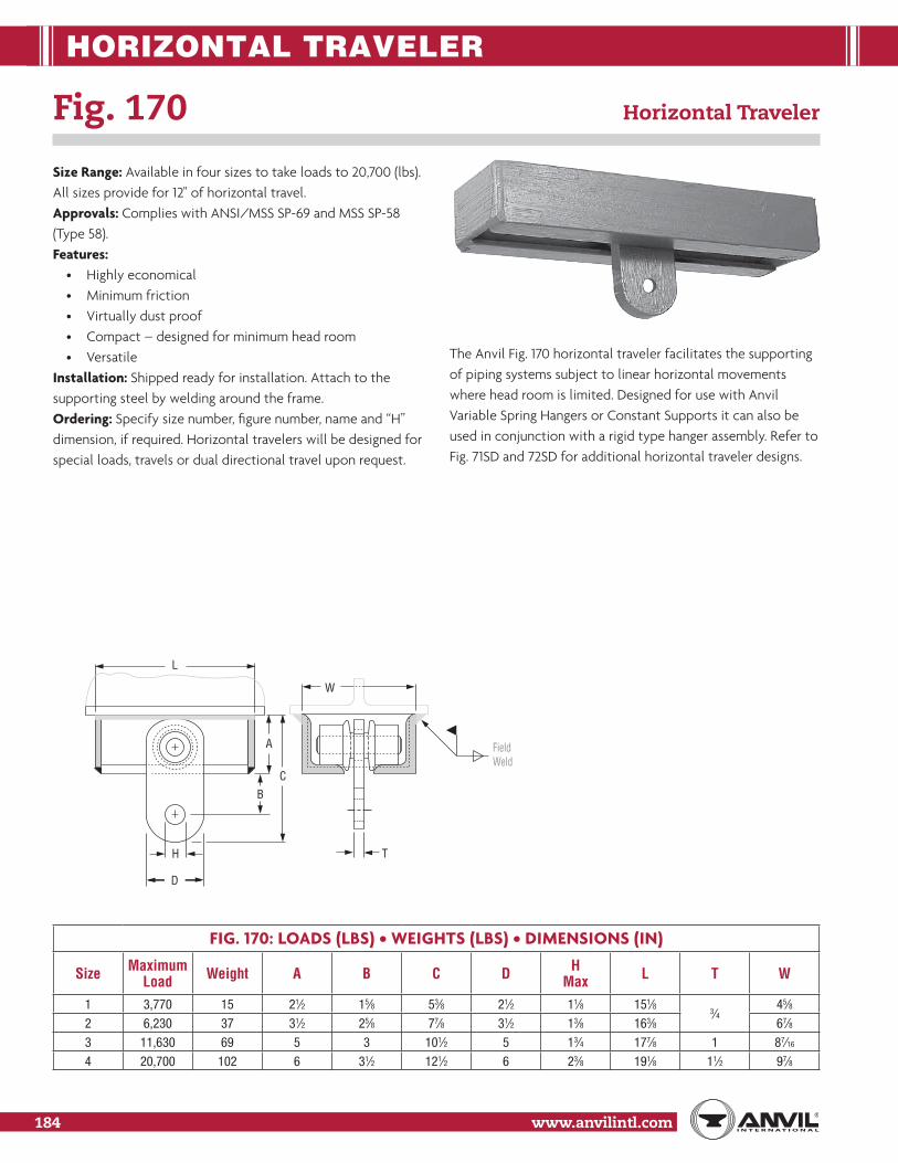
CONSTANT SUPPORTS
www.anvilintl.com184
HORIZONTAL TRAVELER
FIG. 170: LOADS (LBS) • WEIGHTS (LBS) • DIMENSIONS (IN)
Size Maximum Load Weight A B C D H
Max L T W
1 3,770 15 21⁄2 15⁄8 53⁄8 21⁄2 11⁄8 151⁄83⁄4
45⁄8
2 6,230 37 31⁄2 25⁄8 77⁄8 31⁄2 13⁄8 163⁄8 67⁄8
3 11,630 69 5 3 101⁄2 5 13⁄4 177⁄8 1 87⁄16
4 20,700 102 6 31⁄2 121⁄2 6 23⁄8 191⁄8 11⁄2 97⁄8
Size Range: Available in four sizes to take loads to 20,700 (lbs). All sizes provide for 12" of horizontal travel. Approvals: Complies with ANSI/MSS SP-69 and MSS SP-58 (Type 58). Features:
• Highly economical • Minimum friction • Virtually dust proof • Compact – designed for minimum head room • Versatile
Installation: Shipped ready for installation. Attach to the supporting steel by welding around the frame. Ordering: Specify size number, figure number, name and “H” dimension, if required. Horizontal travelers will be designed for special loads, travels or dual directional travel upon request.
Fig. 170 Horizontal Traveler
T
W
H
D
BC
A
L
FieldWeld
The Anvil Fig. 170 horizontal traveler facilitates the supporting of piping systems subject to linear horizontal movements where head room is limited. Designed for use with Anvil Variable Spring Hangers or Constant Supports it can also be used in conjunction with a rigid type hanger assembly. Refer to Fig. 71SD and 72SD for additional horizontal traveler designs.

VIBRATION CONTROL & SWAY BRACE
Stra
psSp
ring
Hang
ers
Cons
tant
Supp
orts
Vibr
atio
n Co
ntro
l&
Sw
ay B
race
Sway
Stru
tAs
sem
bly
Snub
bers
Appl
icatio
nEx
ampl
esSp
ecial
Des
ign
Prod
ucts
Trap
eze
Pipe
Rol
lPi
pe G
uide
s&
Slid
esPi
pe S
hield
s&
Sadd
lesPi
peSu
ppor
tsIn
dex
www.anvilintl.com 185
Tech
nica
lDa
taM
aster
For
mat
3 Pa
rt Sp
ecs.
Fig. 296 Sway Brace
Fig. 301: with Adjustable Preload
Fig. C-296, Fig. C-301: Corrosion Resistant
Size Range: Preloads from 50 to 1,800 pounds and maximum forces from 200 to 7,200 pounds.Finish: Standard finish: painted with semi gloss primer. Corrosion resistant: galvanized with coated coil.Service: Recommended for controlling vibration; absorbing shock loading; guiding or restraining the movement of pipe resulting from thermal expansion; bracing a pipe line against sway.Approvals: Complies with Federal Specification A-A-1192A (Type 55) WW-H-171E (Type 55), ANSI/MSS SP-69 and MSS SP-58 (Type 50).Installation: Shipped ready for installation (see line cuts of Fig. 297, Fig. 298, Fig. 302 and Fig. 303 on page 187 for typical installed hanger assemblies).Adjustment: The sway brace should be in the neutral position when the system is hot and operating, at which time both spring plates should be in contact with the end plates. If they are not, the sway brace should be adjusted to the neutral position by use of the load coupling.Features:
• Vibration is dampened with an instantaneous opposing force bringing the pipe back to normal position.• A single pre-loaded spring provides two way movement.• One spring saves space and simplifies design.• Spring has 3-inch travel in either direction.• Accurate neutral adjustment assured.• A tight fitting connection at rear bracket and clamp.
Additional Features – Fig. 301: The Fig. 301 sway brace is adjustable from the initial preload to the maximum capacity of the unit selected. It is equipped with a load-deflection scale to facilitate preload adjustment. Preload adjustment reduces spring travel accordingly.Ordering: Specify figure, name and sway brace size. The Anvil Fig. 296 and Fig. 301 consist of the sway brace only. Available corrosion resistant as Fig. C-296 and Fig. C-301.Preload adjustment – Fig. 301: Turn the preload adjustment nut until desired preload is indicated. Turn thrust nut until it is in contact with the spring plate. Lock in position. Indicated deflection must be greater than thermal movement.
SPRING PLATESEND PLATES
PRELOADADJ. SCALE
ADJ. NUT
LOCK NUTTHRUST NUT
COUPLING

VIBRATION CONTROL & SWAY BRACE
www.anvilintl.com186
FIG. 301: LOADS • WEIGHTS (LBS) • DIMENSIONS (IN)
Sway Brace Size
Pipe Size
Preload and Spring Scale
(lb/in)
Max Force (lbs)
WeightRod Size Fig. 302
A
EyeD Length
F K L M N P RDia. Hole Thickness
1
11⁄2 to 24
50 200 23 3⁄41 3⁄4 41⁄2
20515⁄16
241⁄477⁄8 1
93⁄16
11⁄42 150 600 261
203⁄4 25 915⁄16
3 450 1,800 38 241⁄8 283⁄8 135⁄16
4 900 3,600 67 11⁄411⁄2 11⁄2 65⁄8
245⁄16
69⁄16
295⁄891⁄4 11⁄2
12113⁄165
6 to 301,350 5,400 82
11⁄22513⁄16 311⁄8 131⁄2
6 1,800 7,200 98 2713⁄16 331⁄8 151⁄2
FIG. 296: LOADS • WEIGHTS (LBS) • DIMENSIONS (IN)
Sway Brace Size
Pipe Size
Preload and Spring Scale
(lb/in)
Max Force (lbs)
WeightRod Size Fig. 297
A
EyeD Length
F K L M N P RDia. Hole Thickness
1
11⁄2 to 24
50 200 22 3⁄41 1 41⁄2
135⁄815⁄8
177⁄861⁄8 1
87⁄811⁄42 150 600 25
1143⁄8 185⁄8 95⁄8
3 450 1,800 36 173⁄4 22 134 900 3,600 64 11⁄4
11⁄2 11⁄2 65⁄817
21⁄4225⁄16
63⁄4 11⁄2111⁄2
113⁄1656 to 30
1,350 5,400 7911⁄2
181⁄2 2313⁄16 136 1,800 7,200 95 201⁄2 2513⁄16 15
Fig. 296, Fig. 301: with Adjustable Preload Sway Brace (cont.)Fig. C-296, Fig. C-301: Corrosion Resistant
Size selection: The Anvil Vibration Control and Sway Brace gives full deflection forces from 200 to 7,200 pounds and has initial precompressed spring forces from 50 to 1,800 pounds to control vibrations and pipe sway. The amount of force needed to control piping should be in proportion to the mass, amplitude of movement, and nature of disturbing forces acting on the pipe. When it is possible to calculate the exact restrain-ing force required, the size of the Vibration Control and Sway Brace capable of providing this force should be selected. As a general reference, the following sizes have been historically used for the pipe sizes shown:
• #1 - 3 1⁄2" and smaller • #2 - 4" to 8" • #3 - 10" to 16" • #4 - 18" to 24" • #5 and #6 - above 24"
Installation: 1) attach rear bracket to structure and pipe at-tachment to piping or equipment. 2) connect coupling to pipe attachment and turn coupling so that spring is compressed in direction opposite to and by approximate amount of piping thermal movement. Important: Final adjustment should be made with the pipe in its hot or operating position. Turn the coupling until both spring plates are in contact with the end plates of the Sway Brace. When correct tension adjustments are completed, the brace exerts no force on the pipe in its operating position. Un-der shutdown conditions, the brace allows the pipe to assume its cold position. It exerts a nominal cold strain force equal to the preload force plus the amount of travel from the hot to cold position, times the spring scale of the particular size of the Vibration Control and Sway Brace.
M
L
R K PF
N2"2"
SPRING PLATEENDPLATE
EYE
ROD COUPLING STANDARDJAM NUT
D
SPRING PLATEENDPLATE
N2"2"
M
L
RK
PF
EYE
A
STANDARDJAM NUT
ROD COUPLING
D
Fig. 296 Fig. 301
PH-11.11

VIBRATION CONTROL & SWAY BRACE
Stra
psSp
ring
Hang
ers
Cons
tant
Supp
orts
Vibr
atio
n Co
ntro
l&
Sw
ay B
race
Sway
Stru
tAs
sem
bly
Snub
bers
Appl
icatio
nEx
ampl
esSp
ecial
Des
ign
Prod
ucts
Trap
eze
Pipe
Rol
lPi
pe G
uide
s&
Slid
esPi
pe S
hield
s&
Sadd
lesPi
peSu
ppor
tsIn
dex
www.anvilintl.com 187
Tech
nica
lDa
taM
aster
For
mat
3 Pa
rt Sp
ecs.
FIG. 297, 298, 302, 303, C-297, C-298,C-302 AND C-303: DIMENSIONS (IN)
Sway Brace Size
WFig. 297, 302 Fig. 298, 303
Min Max Min Max1 715⁄16 24 24 903⁄16
2 89⁄16 24 24 8611⁄16
3 89⁄16 24 24 793⁄16
4 911⁄16 24 24 7413⁄16
5913⁄16 24 241⁄8
6113⁄16
6 4613⁄16
FIG. 297, 298, 302, 303, C-297, C-298, C-302 AND C-303: DIMENSIONS (IN)
Pipe Size
E
Size 1 – 4 Carbon
Size 5 & 6 Carbon
Size 5 & 6 Alloy
11⁄2 41⁄8 – –2 51⁄8 – –
21⁄2 53⁄8 – –3 515⁄16 – –
31⁄2 63⁄16 – –4 61⁄2 – –5 7 – –6 89⁄16 117⁄16 121⁄16
8 99⁄16 127⁄16 131⁄16
10 105⁄8 131⁄2 143⁄812 115⁄8 143⁄4 153⁄814 1211⁄16 153⁄8 1616 1311⁄16 163⁄8 1718 1411⁄16 173⁄8 1820 157⁄8 19 191⁄224 177⁄8 215⁄8 221⁄8
30–
251⁄8 251⁄8–
Fig. 297 and Fig. 298 Sway Brace Assembly
Fig. 302 and Fig. 303: with Adjustable Preload
Fig. C-297, Fig. C-298, Fig. C-302 and Fig. C-303: Corrosion Resistant
The Fig. 297 and Fig. 302 consist of a structural attachment, two studs, the Sway Brace, extension piece up to 2' 0" in length as required, and a modified Fig. 295 pipe clamp. The Fig. 298 and Fig. 303 consist of a structural attachment, two studs, the Sway Brace, adjustableextension piece 2' 1" in length or over as required,an adapter and a toleranced pipe clamp.Note: In specifying Sway Brace assemblies where the “W” dimension exceeds 2' 0" in length, the Fig. 298 or Fig. 303 assembly is required. Verify that calculated “W” is within the min/max shown in table.Ordering assemblies: Specify figure number, name, Sway Brace size, pipe size, “W” dimension. Available corrosion resistant as Fig. C-297, C-298, C-302 and C-303.
FIG. 297FIG. 296 Body
FIG. 296 Body
REAR BRACKET
WPIN3"
STUDEXTENSIONPIECE
FIG. 298
STUD
WFIELD WELD
ADAPTERREAR BRACKET
3" PIN
CL
CL
EOVERALL LENGTH
OVERALL LENGTH
E
ADJUSTABLEEXTENSION PIECE
FFig 296
FIG. 301 Body
FIG. 301 Body
FIG. 302
REAR BRACKET
PIN
3"
STUD
W
FIG. 303
STUD
ADAPTER
REAR BRACKET
PIN3" W
EOVERALL LENGTH
CL
CL
FIELD WELD
E
OVERALL LENGTH
EXTENSIONPIECE
ADJUSTABLEEXTENSION PIECE
FFig 301
PH-11.11

SWAY STRUT ASSEMBLY
www.anvilintl.com188
E-TAKE OUT: DIMENSIONS (IN)
Pipe Size
Size A
Size B & C
Size 1 & 2
Size 3
Size 4
Size 5
Size 6
Size 7
Size 8
3⁄4 27⁄16 – – – – – – – –1 29⁄16 – – – – – – – –
11⁄4 211⁄16 – – – – – – – –11⁄2 41⁄8 – – – – – – – –2 51⁄8 63⁄8 63⁄8 – – – – – –
21⁄2 53⁄87 7 81⁄8
– – – – –3 515⁄16 – – – – –
31⁄2 63⁄16 –
10
– – –4 61⁄2 71⁄4 71⁄4 83⁄8 – – – –5 73⁄4 73⁄4 73⁄4 91⁄8 91⁄8 – – –6 83⁄8 83⁄8 83⁄8 10 10 117⁄8 – –8 93⁄8 93⁄8 93⁄8 111⁄4 111⁄4 111⁄4 125⁄8 – –10 101⁄2 101⁄2 101⁄2 123⁄4 123⁄4 123⁄4 141⁄4 141⁄4 161⁄412 – 117⁄8 117⁄8 137⁄8 137⁄8 137⁄8 153⁄8 153⁄8 171⁄414 – 125⁄8 125⁄8 141⁄2 141⁄2 141⁄2 16 161⁄4 1816 – 135⁄8 135⁄8 151⁄4 151⁄4 151⁄4 171⁄8 171⁄2 1918 – 145⁄8 145⁄8 163⁄8 163⁄8 163⁄8 181⁄4 181⁄2 201⁄420 – 153⁄4 153⁄4 173⁄4 173⁄4 173⁄4 191⁄4 193⁄4 211⁄224 – 181⁄8 181⁄8 197⁄8 197⁄8 197⁄8 213⁄4 213⁄4 2430 – 211⁄4 211⁄4 23 23 23 25 25 2836 – 24 24 261⁄2 261⁄2 261⁄2 281⁄8 281⁄8 311⁄4
Note: "E" Dimensions are for carbon steel clamps only, with maximum insulation of 4" and temperature of 650˚.
Fig. 211, Fig. C-211 Sway Strut Assembly
Fig. 640, Fig. C-640: Field Welded Strut
Finish: Painted (Fig. 211 & Fig. 640) or Galvanized (Fig. C-211 & C-640)Service: Used to restrain movement ofpiping while allowing for movement inthe other two directions.How to size:
(1) Select size consistent with max. load to be restrained.(2) C to C is obtained by subtracting E and A from the distance from structural steel
to center of pipe. Verify that the calculated C to C is within the min/max limits.(3) Determine W dimension by: W=(C to C)-2F.
Installation: Shipped assembled. Securely fasten bracket to structure, make necessary adjustment in overall length, and fasten clamp to pipe.Features:
• Effective under either tensile or compressive force.• Provides 3 1⁄2" (Fig. 211) or 2" (Fig. 640) of field adjustment in either direction.• Self-aligning bushings permits ±5° misalignment or angular motion. Bushings are coated with a dry lubricant.
Ordering: Specify figure number, assembly size, name, option number, normal pipe size or special O.D., and “W” dimension. Alloy pipe clamps are available as a special order. For restraint parallel to the pipe axis using two sway strut assemblies, a riser clamp is available. If a riser clamp is required, consult the nearest Anvil representative for information about this clamp.Note: The rear bracket assembly can be ordered separately.
Note: Second lock nut available by special request only.
PH-11.11

SWAY STRUT ASSEMBLY
Stra
psSp
ring
Hang
ers
Cons
tant
Supp
orts
Vibr
ation
Con
trol
& Sw
ay B
race
Sway
Stru
tAs
sem
bly
Snub
bers
Appl
icatio
nEx
ampl
esSp
ecial
Des
ign
Prod
ucts
Trap
eze
Pipe
Rol
lPi
pe G
uide
s&
Slid
esPi
pe S
hield
s&
Sadd
lesPi
peSu
ppor
tsIn
dex
www.anvilintl.com 189
Tech
nica
lDa
taM
aster
For
mat
3 Pa
rt Sp
ecs.
FIG. 211, C-211, FIG. 640 & FIG. C-640: LOAD (LBS) • DIMENSIONS (IN)
SizeFig. 211 & Fig. 640 Fig. 211 Fig. 640
Load ■
Rod End
Ext. Piece A D D1 N R S T
C-C WF Weld
ZC-C
FMax Min Max Min Max Min
A 650 3⁄4 1 1
2
11⁄4 1⁄4 5⁄8 5⁄8 0.3740.372 60 161⁄2 531⁄8 95⁄8 37⁄16
3⁄16
60 121⁄8 211⁄16
B 1,500 1 11⁄2
21⁄2
23⁄8 5⁄8 13⁄8
13⁄8
0.7490.747 108
19991⁄8 101⁄8
47⁄16
96
147⁄16 311⁄16
C 4,500 12
0.7490.747
120
1111⁄8 101⁄8
1 8,000 11⁄427⁄8 3⁄4 11⁄2
0.9990.997 21 1103⁄8
113⁄8
47⁄8
5⁄16
161⁄2 41⁄8
2 11,630 11⁄221⁄2
0.9990.997 213⁄8 110 5 167⁄8 41⁄4
3 15,700 13⁄43 3 33⁄16 3⁄4 2 111⁄16
1.2491.247 227⁄8 1081⁄2 53⁄4 183⁄8 5
4 20,700 23
1.2491.247 25 108
13
6
3⁄8
201⁄2 51⁄4
5 27,200 21⁄4 4 61⁄8 41⁄4 11⁄4 21⁄2 2 1.4991.497 261⁄2 1061⁄2 63⁄4 22 6
6 33,500 21⁄24
5 77⁄8 53⁄8 13⁄4 3 23⁄8 1.7491.747 281⁄4 1043⁄4 75⁄8 233⁄4 67⁄8
7 68,200 3 53⁄4 91⁄8 61⁄4 2 31⁄2 3 1.9991.997 321⁄2 1021⁄2 15 83⁄4 5⁄8 28 8
8 120,000 4 6 71⁄4 14 83⁄4 21⁄4 43⁄4 33⁄8 2.4992.497 391⁄4 98 171⁄4 11 3⁄4 343⁄4 101⁄4
■ Loads must not be applied outside a 10° included angle cone of action to the pipe clamp axis without special authorization.Fig. 640 shipped at maximum length C-C, field cut to “W” to suit, unless otherwise specified.
Fig. 211, Fig. C-211 Sway Strut Assembly
Fig. 640, Fig. C-640: Field Welded Strut
TLOCKINGNUT
FIG. 640ONLY
S
PIECEEXTENSION
(L.H.)ROD END(R.H.)
ROD END
(INCLUDES PIVOT PIN)(INCLUDES STUD)
PIPE CLAMP
(W = C TO C - 2F)W FF
EA
R
D
REAR BRACKET
D1
T
N
C-C ± 31⁄2" FOR FIG. 211C-C ± 2" FOR FIG. 640
OPTION 1
OPTION 2
OPTION 3
CL
PH-11.11

SWAY STRUT ASSEMBLY
www.anvilintl.com190
Finish: Painted or GalvanizedService: Used to restrain movement of piping in one direction while allowing movement in theother two directions.How to size:
(1) Select size consistent with max. load to be restrained.
(2) C to C is obtained by subtracting E and A from the distance from structural steel to center of pipe. Verify that the calculated C to C is within the min/max limits.
Installation: Shipped assembled. Securely fasten bracket to structure, make necessary adjustment in overall length, and fasten clamp to pipe.Features:• Assembly provides a shorter C to C dimension.• Effective under either tensile or compressive force.• Self-aligning bushings permit ±5 misalignment or angular
motion. Bushings are coated with a dry lubricant.Ordering: Specify assembly size, figure number, name, finish, pipe O.D. or option number, if other than standard, and load. Ex: Size A-1, Fig. 222 mini sway strut 10 3⁄4 O.D. pipe, 650#. Alloy pipe clamps are available as a special order. For restraint parallel to the pipe axis using two sway strut assemblies, a riser clamp is available. Contact your Anvil representative for information about this clamp.Note: The rear bracket assembly can be ordered separately
Fig. 222, C-222 Mini-Sway Strut Assembly
E-TAKE OUT: DIMENSIONS (IN)
Pipe Size
Size A
Size B & C
Size 1
3⁄4 27⁄16 – –
1 29⁄16 – –
11⁄4 211⁄16 – –
11⁄2 41⁄8 – –
2 51⁄8 63⁄8 63⁄8
21⁄2 53⁄8
7 73 515⁄16
31⁄2 63⁄16
4 61⁄2 71⁄4 71⁄4
5 73⁄4 73⁄4 73⁄4
6 83⁄8 83⁄8 83⁄8
8 93⁄8 93⁄8 93⁄8
10 101⁄2 101⁄2 101⁄2
12 – 117⁄8 117⁄8
14 – 125⁄8 125⁄8
16 – 135⁄8 135⁄8
18 – 145⁄8 145⁄8
20 – 153⁄4 153⁄4
24 – 181⁄8 181⁄8
30 – 211⁄4 211⁄4
36 – 24 24Note: "E" Dimensions are for carbon steel clamps only, with maximum insulation of 4" and temperature of 650˚.
PH-11.11

SWAY STRUT ASSEMBLY
Stra
psSp
ring
Hang
ers
Cons
tant
Supp
orts
Vibr
ation
Con
trol
& Sw
ay B
race
Sway
Stru
tAs
sem
bly
Snub
bers
Appl
icatio
nEx
ampl
esSp
ecial
Des
ign
Prod
ucts
Trap
eze
Pipe
Rol
lPi
pe G
uide
s&
Slid
esPi
pe S
hield
s&
Sadd
lesPi
peSu
ppor
tsIn
dex
www.anvilintl.com 191
Tech
nica
lDa
taM
aster
For
mat
3 Pa
rt Sp
ecs.
FIG. 222, C-222: LOADS (LBS) • DIMENSIONS (IN)
Assembly Size
Load ■
C-C FW Rod
End A D D1 N R S T Nom. B
Max Min Max Min
A
A-1
650
65⁄8 53⁄8 213⁄16 19⁄16 25⁄83⁄4 1 2 11⁄4 1⁄4 5⁄8 5⁄8 3⁄8 13⁄16A-2 81⁄2 61⁄2 41⁄4 21⁄4 31⁄16
A-3 131⁄4 81⁄2 61⁄4 11⁄2 513⁄16
B & C
BC-1
4,500
61⁄2 6 27⁄8 23⁄8 11⁄2
1 21⁄2 2 23⁄8 5⁄8 13⁄8 13⁄8 3⁄4 21⁄8
BC-2 73⁄4 65⁄8 31⁄2 23⁄8 21⁄8
BC-3 811⁄16 79⁄16 313⁄16 211⁄16 23⁄4
BC-4 1015⁄16 811⁄16 415⁄16 211⁄16 37⁄8
BC-5 157⁄16 1015⁄16 73⁄16 211⁄16 61⁄8
BC-6 199⁄16 157⁄16 91⁄4 51⁄8 83⁄16
1
1–1
8,000
87⁄8 8 311⁄16 213⁄16 215⁄16
11⁄4 21⁄2 2 27⁄8 3⁄4 19⁄16 13⁄8 1 21⁄4
1–2 105⁄8 87⁄8 49⁄16 213⁄16 313⁄16
1–3 117⁄8 101⁄4 413⁄16 33⁄16 413⁄16
1–4 151⁄8 117⁄8 67⁄16 33⁄16 67⁄16
1–5 215⁄8 151⁄8 911⁄16 33⁄16 911⁄16
■ Loads must not be applied outside a 10° included angle cone of action to the pipe clamp axis without special authorization.
Fig. 222, C-222 Mini-Sway Strut Assembly (cont.)
R
A C-C E
FW
PIPE CLAMP(INCLUDES STUD)
ROD ENDEXTENSION
PIECE
S T
D1
T
N 2 NOITPO1 NOITPO
OPTION 3
PIVOT MOUNT
C-C
SIZESBC-1, BC-2, 1-1 & 1-2
B
(INCLUDES PIVOT PIN)
D
REAR BRACKET
CL
PH-11.11
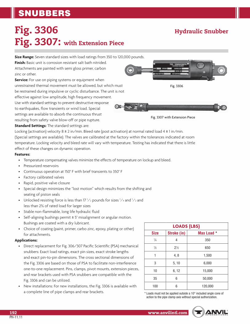
SNUBBERS
www.anvilintl.com192
Fig. 3306 Hydraulic Snubber
Fig. 3307: with Extension Piece
Size Range: Seven standard sizes with load ratings from 350 to 120,000 pounds.Finish: Basic unit is corrosion resistant salt bath nitrided.Attachments are painted with semi gloss primer, carbonzinc or other.Service: For use on piping systems or equipment whenunrestrained thermal movement must be allowed, but which mustbe restrained during impulsive or cyclic disturbance. The unit is noteffective against low amplitude, high frequency movement.Use with standard settings to prevent destructive responseto earthquakes, flow transients or wind load. Specialsettings are available to absorb the continuous thrustresulting from safety valve blow-off or pipe rupture.Standard Settings: The standard settings are: Locking (activation) velocity 8 ± 2 in/min. Bleed rate (post activation) at normal rated load 4 ± 1 in/min. (Special settings are available). The valves are calibrated at the factory within the tolerances indicated at room temperature. Locking velocity and bleed rate will vary with temperature. Testing has indicated that there is littleeffect of these changes on dynamic operation.Features:
• Temperature compensating valves minimize the effects of temperature on lockup and bleed.• Pressurized reservoirs• Continuous operation at 150° F with brief transients to 350° F• Factory calibrated valves• Rapid, positive valve closure• Special design minimizes the “lost motion” which results from the shifting and seating of piston seals• Unlocked resisting force is less than 17 1⁄2 pounds for sizes 1⁄4 and 1⁄2 and less than 2% of rated load for larger sizes• Stable non-flammable, long life hydraulic fluid• Self-aligning bushings permit ± 5° misalignment or angular motion. Bushings are coated with a dry lubricant.• Choice of coating (paint, primer, carbo zinc, epoxy, plating or other) for attachments.
Applications:• Direct replacement for Fig. 306/307 Pacific Scientific (PSA) mechanical snubbers: Exact load ratings, exact pin sizes, exact stroke lengths and exact pin-to-pin dimensions. The cross sectional dimensions of the Fig. 3306 are based on those of PSA to facilitate non-interference one-to-one replacement. Pins, clamps, pivot mounts, extension pieces, and rear brackets used with PSA snubbers are compatible with the Fig. 3306 and can be utilized.• New installations: For new installations, the Fig. 3306 is available with a complete line of pipe clamps and rear brackets.
LOADS (LBS)Size Stroke (in) Max Load *
1⁄4 4 350
1⁄2 21⁄2 650
1 4, 8 1,500
3 5, 10 6,000
10 6, 12 15,000
35 6 50,000
100 6 120,000
* Loads must not be applied outside a 10° included angle cone of action to the pipe clamp axis without special authorization.
Fig. 3306
Fig. 3307 with Extension Piece
PH-11.11

SNUBBERS
Stra
psSp
ring
Hang
ers
Cons
tant
Supp
orts
Vibr
ation
Con
trol
& Sw
ay B
race
Sway
Stru
tAs
sem
bly
Snub
bers
Appl
icatio
nEx
ampl
esSp
ecial
Des
ign
Prod
ucts
Trap
eze
Pipe
Rol
lPi
pe G
uide
s&
Slid
esPi
pe S
hield
s&
Sadd
lesPi
peSu
ppor
tsIn
dex
www.anvilintl.com 193
Tech
nica
lDa
taM
aster
For
mat
3 Pa
rt Sp
ecs.
Fig. 3306 Hydraulic Snubber
Fig. 3307: with Extension Piece
FIG. 3306 & 3307 OPTIONS
Option Consists of…
0Fig 3306: Basic unit (snubber) with pivot mount and one rear bracket.
Fig. 3307: Basic unit with extension piece and one rear bracket.
1 Option 0 plus cylinder eye.
2 Option 0 plus cylinder eye and additional rear bracket.
3 Option 0 plus cylinder eye and pipe clamp.
Stroke – (Algebraic Sum of Movements)
2( )
How to size:(1) Size: Use table on the previous page to select size large
enough to restrain expected load.(2) Stroke: Define expected movement of the pivot joining the
snubber with the equipment to be protected (cold to hot plus any abnormal movements). Determine maximum and minimum distances between this curve and the fixed pivot pin of the snubber. The minimum recommended stroke is 20% greater than the difference between these lengths. Make sure that all normal movement of equipment will be accommodated without the snubber entering the last 1⁄4" (preferably 1⁄2") of the stroke at either end. Note: If erected position at the snubber’s location on the equipment is outside of the range of normal cold-to-hot movement (e.g cold pull of pipe), the snubber should not be installed until after the equipment is in its cold position. This eliminates the need of providing for the extra travel in the snubber’s stroke.
(3) Piston position: To aid in measuring the piston position, we have shown a dimension, “Z”. This dimension represents the distance between the cylinder head and the end of the rod when the rod is fully retracted. Whenever specifying the position at which the piston rod is to be set, the total dimension from the cylinder head to the end of the rod should be given. Thus, piston setting=piston position +Z.
(4) Assembly length: Determine the installed “C” dimension by adding the installed piston position (not setting) to C minimum. Lay in takeout dimensions E and/or B, and find required pin-to-pin snubber length. If a pin-to-pin length adjustment is desired, use Fig. 3307. Calculate the required “W” dimension by subtracting (C installed + F) from the required pin-to-pin length. If this is less than W minimum, only a Fig. 3306 can be used, and one of the attachments will have to be moved or shimmed to suit. If a Fig. 3306 is to be used, make sure that the required pin-to-pin length is at least as great as (C installed + B). If neither a Fig. 3306 nor a Fig. 3307 can be accommodated, and the installation cannot be modified, consult your Anvil representative about designing a special or modified unit.
(5) Installed piston setting: As indicated previously, the snubber should be installed at its cold piston position if possible. From the installed position, take extension (outward movement) of the piston rod as positive (+) and retraction as negative (-). Installed piston position =
Ordering: Specify• Fig. No.• Size• Stroke• Load• Cold and hot piston settings• W dimension when specifying Fig. 3307• Pipe clamp size when specifying option 3• Attachment surface coating• Option
PH-11.11

SNUBBERS
www.anvilintl.com194
Fig. 3306 Hydraulic Shock and Sway Suppressor (cont.)
Fig. 3307: with Extension Piece
FOR SIZES 1/4
FIG. 3306 (OPTION 0)
D
A B
R L P
Z
PISTONSETTING
“P” APPLIES TOSIZES 1/4 - 10
X
X
FEMALE THREAD “H”FOR SIZES 3 - 100MALE THREAD
- 1DEPTH “G”
OPTION 2
OPTION 1
OPTION 3
Q R
A
T
Q RS
T
10°CL
RLM P
C
OVER-ALL ASSEMBLY LENGTH
EWA F±1.00
FIG. 3307 (OPTION 0)
D
BOLT PLATE (SIZES 1⁄4 - 10)SECTION X–X
NOTE: CYLINDER EYE MAY BE ROTATED TO ANY POSITION
K DIA.
NT
D1 10°
PH-11.11

SNUBBERS
Stra
psSp
ring
Hang
ers
Cons
tant
Supp
orts
Vibr
ation
Con
trol
& Sw
ay B
race
Sway
Stru
tAs
sem
bly
Snub
bers
Appl
icatio
nEx
ampl
esSp
ecial
Des
ign
Prod
ucts
Trap
eze
Pipe
Rol
lPi
pe G
uide
s&
Slid
esPi
pe S
hield
s&
Sadd
lesPi
peSu
ppor
tsIn
dex
www.anvilintl.com 195
Tech
nica
lDa
taM
aster
For
mat
3 Pa
rt Sp
ecs.
Fig. 3306 Hydraulic Snubber (cont.)
Fig. 3307: with Extension Piece
FIG 3306, 3307 DIMENSIONS (IN)
*Pipe Size
E-Take Out Clamp Stock SizeSnubber Size Snubber Size
1⁄4 & 1⁄2 1 3 10 35 1⁄4 & 1⁄2 1 3 10 353⁄4 27⁄16 – – – – 3⁄16 x 1 – – – –1 29⁄16 – – – – 3⁄16 x 1 – – – –
11⁄4 211⁄16 – – – – 3⁄16 x 1 – – – –11⁄2 41⁄8 – – – – 1⁄4 x 11⁄4 – – – –2 51⁄8 – – – – 1⁄4 x 11⁄4 – – – –
21⁄2 53⁄8 7 7 7 – 1⁄4 x 11⁄4 3⁄8 x 13⁄4 1⁄2 x 21⁄2 5⁄8 x 21⁄2 –3 515⁄16 7 7 81⁄8 – 1⁄4 x 11⁄4 3⁄8 x 13⁄4 1⁄2 x 21⁄2 5⁄8 x 21⁄2 –
31⁄2 63⁄16 7 7 81⁄8 – 1⁄4 x 11⁄4 3⁄8 x 13⁄4 1⁄2 x 21⁄2 5⁄8 x 21⁄2 –4 61⁄2 71⁄4 71⁄4 83⁄8 – 5⁄16 x 2 1⁄2 x 11⁄2 5⁄8 x 21⁄2 5⁄8 x 21⁄2 –5 73⁄4 73⁄4 73⁄4 91⁄8 – 5⁄16 x 2 1⁄2 x 11⁄2 5⁄8 x 21⁄2 3⁄4 x 3 –6 83⁄8 83⁄8 83⁄8 10 – 5⁄16 x 2 1⁄2 x 2 5⁄8 x 3 3⁄4 x 4 –8 93⁄8 93⁄8 93⁄8 111⁄4 125⁄8 5⁄16 x 2 1⁄2 x 21⁄2 3⁄4 x 3 3⁄4 x 5 1 x 710 101⁄2 101⁄2 101⁄2 123⁄4 141⁄4 5⁄16 x 2 5⁄8 x 21⁄2 3⁄4 x 4 3⁄4 x 6 11⁄4 x 612 – 117⁄8 117⁄8 137⁄8 153⁄8 – 5⁄8 x 21⁄2 3⁄4 x 5 1 x 5 11⁄4 x 614 – 125⁄8 125⁄8 141⁄2 16 – 5⁄8 x 21⁄2 3⁄4 x 5 1 x 5 11⁄4 x 716 – 135⁄8 135⁄8 151⁄4 171⁄8 – 5⁄8 x 3 3⁄4 x 5 1 x 5 11⁄4 x 818 – 145⁄8 145⁄8 163⁄8 181⁄4 – 3⁄4 x 3 3⁄4 x 5 1 x 6 11⁄4 x 920 – 153⁄4 153⁄4 173⁄4 191⁄4 – 3⁄4 x 3 3⁄4 x 5 1 x 7 11⁄2 x 824 – 181⁄8 181⁄8 197⁄8 213⁄4 – 3⁄4 x 4 3⁄4 x 5 1 x 7 11⁄2 x 930 – 211⁄4 211⁄4 23 25 – 3⁄4 x 4 3⁄4 x 6 1 x 7 11⁄2 x 1036 – 24 24 261⁄2 281⁄8 – 3⁄4 x 5 3⁄4 x 7 1 x 7 11⁄2 x 10
* Intermediate sizes between 20 and 36 are available and will have the take out and stock of the next larger size.Note: "E" Dimensions are for carbon steel clamps only, with maximum insulation of 4" and temperature of 650˚.
FIG 3306, 3307 DIMENSIONS (IN)
Snubber Size Stroke A B
C *D D1 F G H K
DiaL
DiaM
Dia N P Q Ref
R Max S T
DiaW Max
Pin to Pin
ZMin Mid Max Min Max
1⁄4 4.001.00 1.19
9.0 11.00 13.02.00 1.25 2.94 0.38 3⁄8-16-2A 2.25 2.25 1.31 0.25 0.62 1.19 0.63 0.63 0.374
0.372
3.50 45.5661.50 0.19
1⁄2 2.50 7.5 8.75 10.0 3.50 48.56
14.00
1.62 1.5611.0 13.00 15.0
4.00 1.75 3.00 0.38 3⁄8-16-2A 3.25 2.38 1.31 0.38 0.69 2.00 1.00 1.00 0.499 0.497
3.87 43.50 61.50 0.19
8.00 15.5 19.50 23.5 N/A N/A 25.06 0.13
35.00
2.12 2.6214.0 16.50 19.0
5.00 3.62 4.50 0.75 5⁄8-18-2B 4.62 4.62 2.38 0.50 1.44 2.12 1.38 1.38 0.749 0.747
4.44 37.50 61.00 1.25
10.00 20.0 25.00 30.0 N/A N/A 32.62 2.25
106.00
3.00 4.0616.1 19.10 22.1
7.00 4.00 5.12 1.00 7⁄8-14-2B 5.75 5.75 2.88 1.00 1.62 2.00 1.62 1.38 0.999 0.997
5.19 44.50 71.72 2.10
12.00 23.1 29.10 35.1 N/A N/A 39.16 1.00
35 6.00 4.62 3.00 24.0 27.00 30.0 9.75 6.50 7.75 1.88 17⁄8-12-2B – 6.00 4.50 1.25 – 3.00 2.79 2.00 1.499 1.497 5.25 79.75 117.50 1.48
100 6.00 7.25 3.80 29.0 32.00 35.0 14.0 8.75 8.31 3.00 3-12-2B – 10.00 5.56 2.00 – 3.80 3.44 – – 6.50 74.18 117.50 3.38
* Adapters are available to match existing pin-to-pins.
PH-11.11

SNUBBERS
www.anvilintl.com196
Fig. 200, Fig. C-200 Hydraulic Snubber
Fig. 201, Fig. C-201: with Extension Piece
Size Range: Seven standard sizes with cylinder bores of 1 1⁄2" to 8" and with normal load ratings from 3,000 pounds to 128,000 pounds. All are available with 5", 10", 15", or 20" strokes except the 1 1⁄2" size which is offered with 5” and 10” strokes only. Snubbers are available withintegral or remote reservoirs.Finish: Fig. 200/201 painted with semi gloss primer. Fig. C-200/C-201 corrosion resistant; painted with carbo zinc.Service: For use on piping systems or equipment when unrestrained thermal movement must be allowed, but which must be restrained during impulsive or cyclic disturbance. The unit is not effective against low amplitude, high frequency movement. Use with standard settings to prevent destructive response to earthquakes, flowtransients or wind load. Special settings are available to absorbthe continuous thrust resulting from safety valveblow-off or pipe rupture.Standard settings: The standard settings are:Locking (activation) velocity 8 +/- 2 in/min. Bleed rate (post activation) at normal rated load 4 +/- 1 in/min. (Special settings are available). The valves are calibrated at the factory within the tolerances indicated at room temperature. Locking velocity andbleed rate will vary with temperature. Testing has indicated that thereis little effect of these changes on dynamic operation.Features:
• Choice of valve type ❒ Adjustable – permits field adjustments ❒ Temperature compensating – minimizes the effects of temperature on lockup and bleed• Choice of reservoir type ❒ Transparent – continuous operation at 200° F with brief transients to 250° F ❒ Metal or pressurized metal – allows brief transients to 340° F ❒ Pressurized – eliminates the concern of reservoir orientation relative to valve and cylinder – minimizes internal contamination ❒ Remote• Factory calibrated valves• Rapid, positive valve closure• Special design minimizes the “lost motion” which results from the shifting and seating of piston seals• Unlocked resisting force is less than 1% of rated load• Stable, non-flammable, long life hydraulic fluid made highly visible for ease of inspection• Self-aligning bushings permit ± 5° misalignment or angular motion. Bushings are coated with a dry lubricant.• Choice of coating (paint, primer, carbo zinc, epoxy, plating or other)
LOADS (LBS)Cylinder Size (in) Max Load *
11⁄2 (5" stroke) 3,000
11⁄2 (10" stroke) 1,250
21⁄2 (5", 10", 15" stroke) 12,500
21⁄2 (20" stroke) 10,500
31⁄4 21,000
4 32,000
5 50,000
6 72,000
8 128,000
* Loads must not be applied outside a 10° included angle cone of action to the pipe clamp axis without special authorization.
PH-11.11

SNUBBERS
Stra
psSp
ring
Hang
ers
Cons
tant
Supp
orts
Vibr
ation
Con
trol
& Sw
ay B
race
Sway
Stru
tAs
sem
bly
Snub
bers
Appl
icatio
nEx
ampl
esSp
ecial
Des
ign
Prod
ucts
Trap
eze
Pipe
Rol
lPi
pe G
uide
s&
Slid
esPi
pe S
hield
s&
Sadd
lesPi
peSu
ppor
tsIn
dex
www.anvilintl.com 197
Tech
nica
lDa
taM
aster
For
mat
3 Pa
rt Sp
ecs.
Upgrade Kits: Kits are available to upgrade existing snubbers with temperature compensating valves and/or pressurized reservoir.How to size:(1) Cylinder size: Use table on page 199 to select cylinder bore
size large enough to restrain expected load.(2) Stroke: Define expected movement of the pivot joining the
suppressor with the equipment to be protected (cold to hot plus any abnormal movements). Determine maximum and minimum distances between this curve and the fixed pivot pin of the snubber. The minimum recommended stroke is 20% greater than the difference between these lengths. Note: If erected position at the snubber’s location on the equipment is outside of the range of normal cold-to-hot movement (e.g. cold pull of pipe), the snubber should not be installed until after the equipment is in its cold position. This eliminates the need of providing for the extra travel in the snubber’s stroke. For 2 1⁄2" through 8" snubbers, standard strokes are 5", 10", 15", and 20". For the 1 1⁄2" snubber, 5" and 10" are the only standard strokes.
(3) Installed piston setting: As indicated previously, the snubber should be installed at its cold piston position if possible. From the installed position, take extension (outward movement) of the piston rod as positive (+) and retraction as negative (-).
(4) Installed piston position =
FIG. 200 & FIG. 201 OPTIONS
Option Consists of…
0Fig 200: Basic unit (snubber) with pivot mount and one rear bracket.
Fig. 201: Basic unit with extension piece and one rear bracket.
1 Option 0 plus cylinder eye.
2 Option 0 plus cylinder eye and additional rear bracket.
3 Option 0 plus cylinder eye and pipe clamp.
Stroke – (Algebraic Sum of Movements)
2( )
To aid in measuring the piston position, we have shown a dimension, “Z”. This dimension represents the distance between the cylinder head and the end of the rod when the rod is fully retracted. Whenever specifying the position at which the piston rod is to be set, the total dimension from the cylinder head to the end of the rod should be given. Thus, Piston Setting = Piston Position + Z.
(5) Assembly length: Determine the installed “C” dimension by adding the installed piston position (not setting) to C minimum. Lay in take out dimensions E and/or B, and find required pin-to-pin snubber length. If a pin-to-pin length adjustment is desired, use Fig. 201. Calculate the required “W” dimension by subtracting (C installed + F) from the required pin-to-pin length. If this is less than W minimum, only a Fig. 200 can be used, and one of the attachments will have to be moved or shimmed to suit. If a Fig. 200 is to be used, make sure that the required pin-to-pin length is at least as great as (C installed + B). If neither a Fig. 200 nor a Fig. 201 can be accommodated, and the installation cannot be modified, consult your Anvil representative about designing a special or modified unit.
Fig. 200, Fig. 201 Hydraulic Snubber (cont.)
Ordering:
Ordering: Specify part number as follows:
XXX X XX X X X X
Reservoir OrientationO=Does not apply for pressurized or remoteU=Rod upD=Rod down or horizontal
Reservoir TypeL=Transparent (Polycarbonate)M=Metal (limited applications)P=PressurizedR=Remote
Valve TypeA=AdjustableT=Temperature Compensating
Option (0,1,2, or 3), See Option Table Below
Stroke (5, 10, 15, 20)
Cylinder Size:1 (11⁄2 Cyl.)2 (21⁄2 Cyl.)3 (31⁄4 Cyl.)4 (4Cyl.)5 (5Cyl.)6 (6Cyl.)8 (8 Cyl.)
Figure No. (200 or 201), Also Specify:W Dimension when Specifying Fig 201Pipe Clamp Size when Specifying Option 3Surface CoatingCold and Hot Piston Settings.
PH-11.11

SNUBBERS
www.anvilintl.com198
Fig. 200, Fig. 201 Hydraulic Snubber (cont.)
U.S. PATENT NO 3106992
CUSTOMERS MARK NO SERIAL NO.
STROKE HOT P.S.SIZE COLD P.S.
SUPPRESSORHYDRAULIC SHOCK & SWAY
FIG. 200
FIG. 200 (OPTION 0)SECTION X-X
I
L KVENTPORT
A BR
X
X
FEMALE THREAD "H"FOR 21/2"-8" CYL.
MALE THREAD FOR11/2" CYLINDER
DEPTH "G"PISTONSETTING
Z
U.S. PATENT NO 3106992
CUSTOMERS MARK NO
SERIAL NO.
STROKE HOT P.S.SIZE COLD P.S.
SUPPRESSORHYDRAULIC SHOCK & SWAY
FIG. 200
FIG. 201 (OPTION 0)
OPTION 2
OPTION 3
OPTION 1
OVER-ALL ASSEMBLY LENGTH
A F ± 31/2" W C E
RT
D
N
D1 10°
Q R
A
T
Q R
S
T
10°
NOTE:CYLINDER EYEMAY BE ROTATEDTO ANY POSITION
CL
PH-11.11

SNUBBERS
Stra
psSp
ring
Hang
ers
Cons
tant
Supp
orts
Vibr
ation
Con
trol
& Sw
ay B
race
Sway
Stru
tAs
sem
bly
Snub
bers
Appl
icatio
nEx
ampl
esSp
ecial
Des
ign
Prod
ucts
Trap
eze
Pipe
Rol
lPi
pe G
uide
s&
Slid
esPi
pe S
hield
s&
Sadd
lesPi
peSu
ppor
tsIn
dex
www.anvilintl.com 199
Tech
nica
lDa
taM
aster
For
mat
3 Pa
rt Sp
ecs.
Fig. 200, Fig. 201 Hydraulic Snubber (cont.)
FIG 200, 201: DIMENSIONS (IN)
Pipe Size
E-Take Out Clamp Stock SizeCylinder Bore Cylinder Bore
11⁄2 21⁄2 31⁄4 4 5 6 11⁄2 21⁄2 31⁄4 4 5 62 6 63⁄8 – – – – 3⁄8 x 13⁄4 1⁄2 x 21⁄2 – – – –
21⁄2 7 7 – – – – 3⁄8 x 13⁄4 1⁄2 x 21⁄2 – – – –3 7 7 – – – – 3⁄8 x 13⁄4 1⁄2 x 21⁄2 – – – –
31⁄2 7 7 – – – – 3⁄8 x 13⁄4 1⁄2 x 21⁄2 – – – –4 71⁄4 71⁄4 – – – – 1⁄2 x 11⁄2 5⁄8 x 21⁄2 – – – –5 73⁄4 73⁄4 91⁄8 10 – – 1⁄2 x 11⁄2 5⁄8 x 21⁄2 3⁄4 x 3 3⁄4 x 5 – –6 83⁄8 83⁄8 10 10 117⁄8 – 1⁄2 x 2 5⁄8 x 3 3⁄4 x 4 3⁄4 x 5 1 x 5 –8 93⁄8 93⁄8 111⁄4 111⁄4 125⁄8 – 1⁄2 x 21⁄2 3⁄4 x 3 3⁄4 x 5 1 x 5 1 x 6 –
10 101⁄2 101⁄2 123⁄4 123⁄4 141⁄4 – 5⁄8 x 21⁄2 3⁄4 x 4 3⁄4 x 6 1 x 5 1 x 7 –12 117⁄8 117⁄8 137⁄8 137⁄8 153⁄8 – 5⁄8 x 21⁄2 3⁄4 x 5 1 x 5 1 x 6 1 x 7 –14 125⁄8 125⁄8 141⁄2 141⁄2 16 – 5⁄8 x 21⁄2 3⁄4 x 5 1 x 5 1 x 7 11⁄4 x 6 –16 135⁄8 135⁄8 151⁄4 151⁄4 171⁄8 – 5⁄8 x 3 3⁄4 x 6 1 x 5 1 x 7 11⁄4 x 6 –18 145⁄8 145⁄8 163⁄8 163⁄8 181⁄4 – 3⁄4 x 3 1 x 5 1 x 6 1 x 7 11⁄4 x 7 –20 153⁄4 153⁄4 173⁄4 173⁄4 191⁄4 191⁄4 3⁄4 x 3 1 x 5 1 x 7 11⁄4 x 6 11⁄4 x 8 11⁄2 x 824 181⁄8 181⁄8 197⁄8 197⁄8 213⁄4 213⁄4 3⁄4 x 4 1 x 5 1 x 7 11⁄4 x 6 11⁄4 x 9 11⁄2 x 930 211⁄4 211⁄4 23 23 25 25 3⁄4 x 4 1 x 6 11⁄4 x 6 11⁄4 x 8 11⁄2 x 8 13⁄4 x 1036 24 24 261⁄2 261⁄2 281⁄8 281⁄8 3⁄4 x 5 1 x 7 11⁄4 x 6 11⁄4 x 9 11⁄2 x 10 13⁄4 x 10
Note: "E" Dimensions are for carbon steel clamps only, with maximum insulation of 4" and temperature of 650˚.
FIG 200, 201: WEIGHT (LBS) • DIMENSIONS (IN)Cylinder Fig.
200 Wt.
A BC
D D1 F G HI
K L N Q R S TW
ZBore Stroke Min Mid Max Metal
Res.Trans. Res.
Press Res. Min Max
11⁄25 45
21⁄2 15⁄8131⁄8 155⁄8 181⁄8
2 23⁄8 6 3⁄4 5⁄8–18 59⁄16 413⁄16 43⁄4 23⁄4 21⁄4 5⁄8 21⁄8 11⁄8 1 3⁄4 91⁄2755⁄8 5⁄8
10 49 181⁄8 231⁄8 281⁄8 655⁄8
21⁄2
5 75
21⁄2 21⁄4
133⁄8 157⁄8 183⁄8
2 27⁄8 73⁄16 7⁄8 7⁄8–14 61⁄4 51⁄8 53⁄4 31⁄4 13⁄4 3⁄4 2 15⁄8 13⁄8 1 103⁄8
949⁄16
110 81 183⁄8 233⁄8 283⁄8 849⁄16
15 87 233⁄8 307⁄8 383⁄8 749⁄16
20 93 283⁄8 383⁄8 483⁄8 649⁄16
31⁄4
5 121
3 3
147⁄8 173⁄8 197⁄8
3 33⁄16 715⁄16 11⁄8 11⁄8–12 67⁄8 53⁄4 63⁄4 33⁄4 21⁄4 3⁄4 21⁄2 21⁄16 111⁄16 11⁄4 101⁄2
92
11⁄810 132 197⁄8 247⁄8 297⁄8 8215 146 247⁄8 323⁄8 397⁄8 7220 156 297⁄8 397⁄8 497⁄8 62
4
5 177
4 33⁄4
161⁄8 185⁄8 211⁄8
61⁄8 41⁄4 95⁄16 11⁄2 11⁄2–12 71⁄8 6 713⁄16 4 21⁄2 11⁄4 33⁄8 21⁄2 2 11⁄2 111⁄2
899⁄16
11⁄810 189 211⁄8 261⁄8 311⁄8 799⁄16
15 206 261⁄8 335⁄8 411⁄8 699⁄16
20 223 311⁄8 411⁄8 511⁄8 599⁄16
5
5 235
5 41⁄2
18 201⁄2 23
77⁄8 53⁄8 103⁄16 17⁄8 17⁄8–12 81⁄2 7 95⁄16 43⁄4 31⁄4 13⁄4 4 31⁄16 23⁄8 13⁄4 12
8613⁄16
17⁄810 256 23 28 33 7613⁄16
15 277 28 351⁄2 43 6613⁄16
20 298 33 43 53 5613⁄16
6
5 292
53⁄4 51⁄2
193⁄4 221⁄4 243⁄4
91⁄8 61⁄4 115⁄16 21⁄4 21⁄4–12 91⁄16 75⁄8 1015⁄16 51⁄4 37⁄8 2 45⁄8 31⁄2 23⁄4 2 133⁄8
8315⁄16
13⁄410 320 243⁄4 293⁄4 343⁄4 7315⁄16
15 348 293⁄4 371⁄4 443⁄4 6315⁄16
20 375 343⁄4 443⁄4 543⁄4 5315⁄16
8
5 515
71⁄4 6
231⁄2 26 281⁄2
14 83⁄4 141⁄2 4 3–12 121⁄2 N/A 131⁄8 81⁄2 47⁄8 21⁄4 63⁄4 43⁄4 – 21⁄2 141⁄2
751⁄2
21⁄410 575 281⁄2 331⁄2 381⁄2 651⁄215 640 331⁄2 41 481⁄2 551⁄220 705 381⁄2 481⁄2 581⁄2 451⁄2
PH-11.11

SNUBBERS
www.anvilintl.com200
Fig. 312 Tapered Pin
Size Range: 3⁄8" through 2 1⁄2"Service: Used as a replacement to standard rear bracket load pin to facilitate easy removal at time of rebuild or testing. May be supplied with new orders, when specified.How to size: Select size consistent with load pin diameter for Fig. 200/201 or Fig. 3306/3307.Features:
• Designed to sharply reduce the time necessary to remove a badly corroded conventional pin and may also eliminate damage to the bushing and bracket assembly, particularly if the pin and bracket are corroded.• Minimizes “free play” between pin to pin.
Ordering: Specify figure number, nominal pin size and name.Installation: Shipped assembled. Remove nuts and washer. Loosen sleeve on pin and installsleeve/pin. Re-install washer and one nut. Tighten hex nut to snug. Install second nut.
FIG 312: LOADS (LBS) • DIMENSIONS (IN)
Nominal Dia. T Max Load LCompatible With
Fig. 200/201 Fig. 3306/33073⁄8 650 161⁄64 – 1⁄4 & 1⁄21⁄2 1,500 23⁄8 – 13⁄4 6,000 37⁄8 11⁄2 3
1 15,000 43⁄8 21⁄2 10
11⁄4 21,000 41⁄2 31⁄4 –
11⁄2 50,000 71⁄8 4 35
13⁄4 50,000 63⁄4 5 –
2 72,000 73⁄4 6 –
21⁄2 128,000 93⁄8 8 100
The load must be applied by a spherical bearing.
(NOMINAL)T
L (REF)
PH-11.11
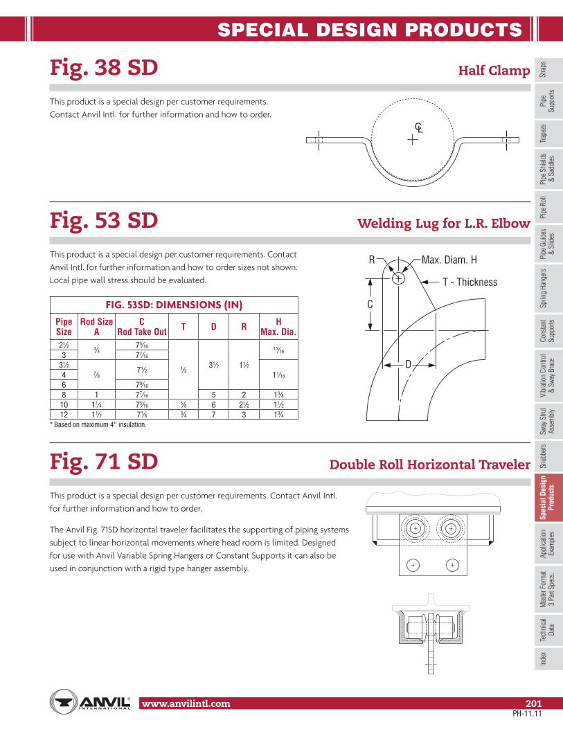
SPECIAL DESIGN PRODUCTS
Stra
psSp
ring
Hang
ers
Cons
tant
Supp
orts
Vibr
ation
Con
trol
& Sw
ay B
race
Sway
Stru
tAs
sem
bly
Snub
bers
Appl
icatio
nEx
ampl
esSp
ecia
l Des
ign
Prod
ucts
Trap
eze
Pipe
Rol
lPi
pe G
uide
s&
Slid
esPi
pe S
hield
s&
Sadd
lesPi
peSu
ppor
tsIn
dex
www.anvilintl.com 201
Tech
nica
lDa
taM
aster
For
mat
3 Pa
rt Sp
ecs.
Fig. 38 SD Half Clamp
This product is a special design per customer requirements. Contact Anvil Intl. for further information and how to order.
Fig. 53 SD Welding Lug for L.R. Elbow
This product is a special design per customer requirements. ContactAnvil Intl. for further information and how to order sizes not shown. Local pipe wall stress should be evaluated.
Fig. 71 SD Double Roll Horizontal Traveler
This product is a special design per customer requirements. Contact Anvil Intl. for further information and how to order.
The Anvil Fig. 71SD horizontal traveler facilitates the supporting of piping systems subject to linear horizontal movements where head room is limited. Designed for use with Anvil Variable Spring Hangers or Constant Supports it can also be used in conjunction with a rigid type hanger assembly.
FIG. 53SD: DIMENSIONS (IN)
Pipe Size
Rod Size A
C Rod Take Out T D R H
Max. Dia.21⁄2 3⁄4
75⁄16
1⁄231⁄2 11⁄2
15⁄163 77⁄16
31⁄27⁄8
71⁄211⁄164
6 79⁄16
8 1 77⁄16 5 2 13⁄810 11⁄4 75⁄16 5⁄8 6 21⁄2 11⁄212 11⁄2 71⁄8 3⁄4 7 3 13⁄4
* Based on maximum 4" insulation.
CL
D
C
T - Thickness
Max. Diam. HR
PH-11.11

SPECIAL DESIGN PRODUCTS
www.anvilintl.com202
Fig. 75 SD Flat Roller With Saddle
This product is a special design per customer requirements. Contact Anvil Intl. for further information and how to order. Pipe sizes 4" through 42"Note: Type B Saddle - If attached to alloy pipe, furnishmaterial specification applicable to the pipe. (Alloy Barsfurnished for attachment to alloy pipe only.)
Fig. 76 SD Fabricated Roller for Large Diameter Pipe
This product is a special design per customer requirements. Contact Anvil International for further information and how to order.Installation: The two piece fabricated roller is designed for one of the two rollers on each side of the assembly to be in contact with the pipe.
FIG. 76SD: LOADS (LBS) • DIMENSIONS (IN)Steel
Pipe SizeMax Load A B C D E
30
60,000
231⁄8
135⁄8 83⁄16
815⁄16 036 26 915⁄16 142 287⁄8 1015⁄16 246 303⁄4 1111⁄16 23⁄446
60,000
313⁄16
161⁄4 1013⁄16
1213⁄16 11⁄448 321⁄16 131⁄4 111⁄16
54 3415⁄16 145⁄16 23⁄460 3711⁄16 151⁄2 315⁄16
66 409⁄16 169⁄16 572 433⁄8 175⁄8 61⁄16
Fig. 72 SD Dual Direction Horizontal Traveler
This product is a special design per customer requirements. Contact AnvilInternational for further information and how to order.
The Anvil Fig. 72SD Horizontal Traveler facilitates the supporting of piping systemssubject to dual directional horizontal movements where head room is limited. Designedfor use with Anvil Variable Spring Hangers or Constant Supports, it can also beused in conjunction with a rigid type hanger assembly.
A
43/16
OF PIPE
CL
ALL DIMENSIONS TYPICAL
1
E
7
D
BC
15/16
11 /4
6 31 /2
OF PIPECL
CL OF PIPE
FIG. 76SD: LOADS (LBS) • DIMENSIONS (IN)C.I./D.I.Pipe Size
Max Load A B C D E
3060,000
243⁄16
135⁄8 83⁄16
91⁄16 1⁄436 273⁄16 103⁄16 13⁄842 301⁄8 115⁄16 23⁄848 60,000 331⁄2 161⁄4 1013⁄16 139⁄16 2
with Type A Saddle with Type B Saddle
PH-11.11

SPECIAL DESIGN PRODUCTS
Stra
psSp
ring
Hang
ers
Cons
tant
Supp
orts
Vibr
ation
Con
trol
& Sw
ay B
race
Sway
Stru
tAs
sem
bly
Snub
bers
Appl
icatio
nEx
ampl
esSp
ecia
l Des
ign
Prod
ucts
Trap
eze
Pipe
Rol
lPi
pe G
uide
s&
Slid
esPi
pe S
hield
s&
Sadd
lesPi
peSu
ppor
tsIn
dex
www.anvilintl.com 203
Tech
nica
lDa
taM
aster
For
mat
3 Pa
rt Sp
ecs.
S
A
H
E
BOLT DIA.AND LENGTH F
CL
Fig. 40 SD Riser Clamp
Material: Carbon steel chrome molybdenum or stainless steel.Finish: Plain or GalvanizedMaximum Temperature: As required.Ordering: Specify figure number 40SD, riser clamp special design, material, exact pipe size, load, operating temperature, insulation thickness, C-C dimension, rod diameter, finish andif connected to a spring or rigid connection.Service: Riser clamps are used for the support of verticalpiping. Load is carried by shear lugs which are welded tothe pipe. Shear lugs not provided.
PIPESPACER
BOLT DIAM B.LENGTH "F"
A*C to C
A*
A
S
K
CL
Fig. 41 SD Non-Standard Three Bolt Pipe Clamp
Ordering: Specify Fig. 41SD double bolt pipe clamp, material specification, pipe size, load, operating temperature, insulation thickness and finish. Alloy clamps, unless otherwise specified, will be furnished with alloy studs made from ASTM A 193-B7 stud stock and ASTM A 194-Gr. 2H hex nuts.
PH-11.11

SPECIAL DESIGN PRODUCTS
www.anvilintl.com204
Fig. 42 SD Non-Standard Two Bolt Pipe Clamp
Ordering: Specify Fig. 42SD pipe clamp, material specification, pipe size, load, temperature and finish. Alloy clamps, unless otherwise specified, will be furnished with alloy studs made from ASTM A 193-B7 stud stock and ASTM A 194-Gr. 2H hex nuts.
A
H
E
BOLT/STUDDIAMETER
CL
PH-11.11

APPLICATION ASSEMBLY EXAMPLES
Stra
psSp
ring
Hang
ers
Cons
tant
Supp
orts
Vibr
ation
Con
trol
& Sw
ay B
race
Sway
Stru
tAs
sem
bly
Snub
bers
Appl
icat
ion
Exam
ples
Spec
ial D
esig
nPr
oduc
tsTr
apez
ePi
pe R
oll
Pipe
Gui
des
& Sl
ides
Pipe
Shi
elds
& Sa
ddles
Pipe
Supp
orts
Inde
x
www.anvilintl.com 205
Tech
nica
lDa
taM
aster
For
mat
3 Pa
rt Sp
ecs.
Each of these drawings are available on the Anvil web site in CAD format. The file name at the bottom of each box refers to that CAD file.
Constant Hanger Assemblies
140, 146
80V TYPE A
290
295, 295A, 295H
C-C(NEEDED)
140, 146
290
40
66
80 VTYPE B
Fig_80V_Type_A .DWG, .DXF, or .EPS Fig_80V_Type_B .DWG, .DXF, or .EPS
140, 146
224, 246
55L
80 VTYPE C
291
140, 146
80V TYPE D
290
295, 295A, 295H
140, 146
80V TYPE E
290
295, 295A, 295H
(NEEDED)C-C
290
140, 146
60
160-166A
66
80 V TYPE G137 S
66
140, 146
140, 146
290
81-H TYPE A
224, 246
290
290
295, 295A, 295H
66
140, 146
290
81-H TYPE A
Fig_80V_Type_C .DWG, .DXF, or .EPS Fig_80V_Type_D .DWG, .DXF, or .EPS Fig_80V_Type_E .DWG, .DXF, or .EPS
Fig_80V_Type_G .DWG, .DXF, or .EPS Fig_81H_Type_A_224 .DWG, .DXF, or .EPS Fig_81H_Type_A_295 .DWG, .DXF, or .EPS
PH-11.11

APPLICATION ASSEMBLY EXAMPLES
www.anvilintl.com206
Constant Hanger Assemblies (continued)
Fig_81H_Type_B_295 .DWG, .DXF, or .EPS Fig_81H_Type_B_SD .DWG, .DXF, or .EPS
140, 146
66
290
295, 295A, 295H
81-H TYPE B
299
ELBOW
140, 146
53-SD WELD LUG
66
81-H TYPE B
140, 146
290
295, 295A, 295H
81-H TYPE C
55 LUG291
81-H TYPE D
299
ELBOW
140, 146
53-SD WELD LUG
81 HTYPE F
Each of these drawings are available on the Anvil web site in CAD format. The file name at the bottom of each box refers to that CAD file.
Fig_81H_Type_C .DWG, .DXF, or .EPS
Fig_81H_Type_D .DWG, .DXF, or .EPS Fig_81H_Type_F .DWG, .DXF, or .EPS
PH-11.11

APPLICATION ASSEMBLY EXAMPLES
Stra
psSp
ring
Hang
ers
Cons
tant
Supp
orts
Vibr
ation
Con
trol
& Sw
ay B
race
Sway
Stru
tAs
sem
bly
Snub
bers
Appl
icat
ion
Exam
ples
Spec
ial D
esig
nPr
oduc
tsTr
apez
ePi
pe R
oll
Pipe
Gui
des
& Sl
ides
Pipe
Shi
elds
& Sa
ddles
Pipe
Supp
orts
Inde
x
www.anvilintl.com 207
Tech
nica
lDa
taM
aster
For
mat
3 Pa
rt Sp
ecs.
Each of these drawings are available on the Anvil web site in CAD format. The file name at the bottom of each box refers to that CAD file.
Spring Hanger Assemblies
SH_Type_A_212 .DWG, .DXF, or .EPS SH_Type_A_60 .DWG, .DXF, or .EPS
290
140, 146
66
82, 268, 98 TYPE A
290
212, 216
140, 146 290
140, 146
66
82, 268, 98 TYPE A
290
295, 295A, 295H
140, 146
140, 146
82, 268, 98 TYPE A
290
295, 295A, 295H
140, 146
60
SH_Type_A_295 .DWG, .DXF, or .EPS
290
140, 146
ELBOW
TYPE A 82, 268, 98
66
299
140, 146
53-SD WELD LUG
60
140, 146
140, 146
ELBOW
TYPE A82, 268, 98
299
53-SD WELD LUG
C-C(NEEDED)
290
140, 146
140, 146
290
40
82, 268, 98 TYPE A
66
SH_Type_A_53SD .DWG, .DXF, or .EPS SH_Type_A_53SD_60 .DWG, .DXF, or .EPS SH_Type_A_Riser .DWG, .DXF, or .EPS
82, 268, 98
295, 295A, 295H
290
TYPE B
66
140, 146 140, 146
ELBOW
TYPE B 82, 268, 98
299
53-SD WELD LUG
66
82, 268, 98
55L
TYPE C
212, 216
290
291
140, 146
SH_Type_B_295 .DWG, .DXF, or .EPS SH_Type_B_53SD .DWG, .DXF, or .EPS SH_Type_C_212 .DWG, .DXF, or .EPS
PH-11.11
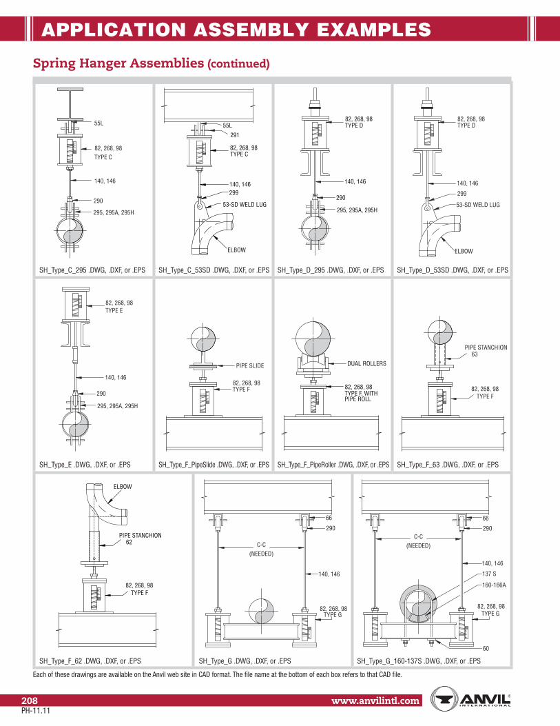
APPLICATION ASSEMBLY EXAMPLES
www.anvilintl.com208
Spring Hanger Assemblies (continued)
SH_Type_C_295 .DWG, .DXF, or .EPS
Each of these drawings are available on the Anvil web site in CAD format. The file name at the bottom of each box refers to that CAD file.
82, 268, 98
55L
TYPE C
295, 295A, 295H
290
140, 146 140, 146
ELBOW
TYPE C82, 268, 98
299
53-SD WELD LUG
55L
291
140, 146
82, 268, 98TYPE D
290
295, 295A, 295H
299
ELBOW
140, 146
53-SD WELD LUG
82, 268, 98TYPE D
SH_Type_C_53SD .DWG, .DXF, or .EPS SH_Type_D_295 .DWG, .DXF, or .EPS SH_Type_D_53SD .DWG, .DXF, or .EPS
140, 146
82, 268, 98TYPE E
290
295, 295A, 295H
82, 268, 98TYPE F
PIPE SLIDE
82, 268, 98TYPE F, WITHPIPE ROLL
DUAL ROLLERS
82, 268, 98TYPE F
PIPE STANCHION63
SH_Type_E .DWG, .DXF, or .EPS SH_Type_F_PipeSlide .DWG, .DXF, or .EPS SH_Type_F_PipeRoller .DWG, .DXF, or .EPS SH_Type_F_63 .DWG, .DXF, or .EPS
82, 268, 98TYPE F
PIPE STANCHION
ELBOW
62
(NEEDED)C-C
290
140, 146
TYPE G
66
82, 268, 98
(NEEDED)C-C
290
140, 146
137 S
60
160-166A
TYPE G
66
82, 268, 98
SH_Type_F_62 .DWG, .DXF, or .EPS SH_Type_G .DWG, .DXF, or .EPS SH_Type_G_160-137S .DWG, .DXF, or .EPS
PH-11.11

APPLICATION ASSEMBLY EXAMPLES
Stra
psSp
ring
Hang
ers
Cons
tant
Supp
orts
Vibr
ation
Con
trol
& Sw
ay B
race
Sway
Stru
tAs
sem
bly
Snub
bers
Appl
icat
ion
Exam
ples
Spec
ial D
esig
nPr
oduc
tsTr
apez
ePi
pe R
oll
Pipe
Gui
des
& Sl
ides
Pipe
Shi
elds
& Sa
ddles
Pipe
Supp
orts
Inde
x
www.anvilintl.com 209
Tech
nica
lDa
taM
aster
For
mat
3 Pa
rt Sp
ecs.
Rigid Hanger Assemblies
Each of these drawings are available on the Anvil web site in CAD format. The file name at the bottom of each box refers to that CAD file.
(NEEDED)C-C
290
140,146
290
40
230
253
66290
140, 146
66
290
212, 216
29066
140
253
230
295, 295A, 295H
290
290
140, 146
FIG. 230 TURNBUCKLEAND FIG. 253 RODMAY BE ADDED FORVERTICAL ADJUSTMENT
ELBOW
66
299
53-SD WELD LUG
RH_40_290_230_Riser .DWG, .DXF, or .EPS RH_212_290_140_66 .DWG, .DXF, or .EPS RH_295_290_230 .DWG, .DXF, or .EPS RH_53SD_299_290 .DWG, .DXF, or .EPS
140, 146
260
60
66
290
212, 216
140, 146140, 146
55 LUG299
212, 216
290
140, 146
290
295, 295A, 295H
55 LUG299
RH_260_140_60 .DWG, .DXF, or .EPS RH_212_290 .DWG, .DXF, or .EPS RH_212_290_299_55 .DWG, .DXF, or .EPS RH_295_290_299_55 .DWG, .DXF, or .EPS
45 BACK/BACK CHANNELSIZED BY CUSTOMERSTO MEET LOAD REQ.
ALTERNATEORIENTATIONOF 137S/PIPE
(NEEDED)C-C
60
140, 146
60
137S
(NEEDED)C-C
66
290
230
60
140, 146
140, 146
ALTERNATEORIENTATIONOF 137S/PIPE
137S
45 BACK/BACK CHANNELSIZED BY CUSTOMERSTO MEET LOAD REQ.
RH_45_137S_66_Trapeze .DWG, .DXF, or .EPS RH_45_137S_60_Trapeze .DWG, .DXF, or .EPS
PH-11.11

APPLICATION ASSEMBLY EXAMPLES
www.anvilintl.com210
Rigid Hanger Assemblies (continued)
Each of these drawings are available on the Anvil web site in CAD format. The file name at the bottom of each box refers to that CAD file.
218
157
140, 146
181
218
157
65, 260
140, 146
167
218
157
65, CT-65, 260
140, 146
167
92, 93
140, 146
65, CT-65, 260
RH_181_157_218 .DWG, .DXF, or .EPS RH_167_65_157_218 .DWG, .DXF, or .EPS RH_65_157_218 .DWG, .DXF, or .EPS RH_167_65_92 .DWG, .DXF, or .EPS
295, 295A, 295H
290
HOT SERVICEUP TO 4" INSULATION
228, 292
140, 146
260
228, 292
140, 146212, 216
290
140, 146
228, 292
140, 146
69, CT-69, 70
218
157
RH_295_290_228 .DWG, .DXF, or .EPS RH_260_228 .DWG, .DXF, or .EPS RH_212_290_228 .DWG, .DXF, or .EPS RH_69_157_218 .DWG, .DXF, or .EPS
65, CT-65, 260
140, 146
86
92, 93, 94
140, 146
69, CT-69, 70
60
295, 295A, 295H
290
140, 146
HOT SERVICEUP TO 4" INSULATION
29066
140, 146
295, 295A, 295H
290
RH_65_86 .DWG, .DXF, or .EPS RH_69_92 .DWG, .DXF, or .EPS RH_295_290_60 .DWG, .DXF, or .EPS RH_295_290_66 .DWG, .DXF, or .EPS
PH-11.11

APPLICATION ASSEMBLY EXAMPLES
Stra
psSp
ring
Hang
ers
Cons
tant
Supp
orts
Vibr
ation
Con
trol
& Sw
ay B
race
Sway
Stru
tAs
sem
bly
Snub
bers
Appl
icat
ion
Exam
ples
Spec
ial D
esig
nPr
oduc
tsTr
apez
ePi
pe R
oll
Pipe
Gui
des
& Sl
ides
Pipe
Shi
elds
& Sa
ddles
Pipe
Supp
orts
Inde
x
www.anvilintl.com 211
Tech
nica
lDa
taM
aster
For
mat
3 Pa
rt Sp
ecs.
Rigid Hanger Assemblies (continued)
Each of these drawings are available on the Anvil web site in CAD format. The file name at the bottom of each box refers to that CAD file.
290
140, 146
260
FIG. 230 TURNBUCKLEAND FIG. 253 RODMAY BE ADDED FORVERTICAL ADJUSTMENT
66
60
140, 146
65, 260
167
60
212, 216
290
MEDIUM SERVICEMAX. SERVICE TEMP.650 FOR PIPE CLAMP
140, 146
140, 146
69, CT-69, 70
281, 282, 285
140, 146
281, 282, 285
65, CT-65, 260
140, 146
281, 282, 285
65, 260
167, SEESELECTION CHART
140, 146
69, CT-69, 70
60
65, CT-65, 260
167
140, 146
60
140, 146
181
160 (1" INSUL.)161 (11⁄2" INSUL.)162 (2" INSUL.)163 (21⁄2" INSUL.)164 (3" INSUL.)165 (4" INSUL.)
60
RH_260_290_66 .DWG, .DXF, or .EPS RH_167_65_60 .DWG, .DXF, or .EPS RH_212_290_60 .DWG, .DXF, or .EPS
RH_69_281_CI .DWG, .DXF, or .EPS RH_65_281_CI .DWG, .DXF, or .EPS RH_167_65_281_CI .DWG, .DXF, or .EPS
RH_69_60 .DWG, .DXF, or .EPS RH_160_181_60 .DWG, .DXF, or .EPS RH_167_260_60 .DWG, .DXF, or .EPS
PH-11.11

APPLICATION ASSEMBLY EXAMPLES
www.anvilintl.com212
Rigid Hanger Assemblies (continued)
Each of these drawings are available on the Anvil web site in CAD format. The file name at the bottom of each box refers to that CAD file.
140, 146
160 (1" INSULATION)161 (11⁄2" INSULATION)162 (2" INSULATION)163 (21⁄2" INSULATION)164 (3" INSULATION)165 (4" INSULATION)
171 271
160 (1" INSULATION)161 (11⁄2" INSULATION)162 (2" INSULATION)163 (21⁄2" INSULATION)164 (3" INSULATION)165 (4" INSULATION) 140, 146
171
175
271
140, 146
177
RH_171_160_Trapeze .DWG, .DXF, or .EPS RH_271_160_Support .DWG, .DXF, or .EPS RH_171_Trapeze .DWG, .DXF, or .EPS
RH_175_Support .DWG, .DXF, or .EPS RH_271_Support .DWG, .DXF, or .EPS RH_177_Support .DWG, .DXF, or .EPS
PH-11.11

PIPE HANGER SPECIFICATIONS
Stra
psSp
ring
Hang
ers
Cons
tant
Supp
orts
Vibr
ation
Con
trol
& Sw
ay B
race
Sway
Stru
tAs
sem
bly
Snub
bers
Appl
icatio
nEx
ampl
esSp
ecial
Des
ign
Prod
ucts
Trap
eze
Pipe
Rol
lPi
pe G
uide
s&
Slid
esPi
pe S
hield
s&
Sadd
lesPi
peSu
ppor
tsIn
dex
www.anvilintl.com 213
Tech
nica
lDa
taM
aste
r For
mat
3 Pa
rt Sp
ecs.
1. SCOPE This specification shall apply for the design and fabrication of all hangers, supports, anchors, and guides. Where piping design is such that exceptions to this specification are necessary, the particular system will be identified, and the exceptions clearly listed through an addendum which will be made a part of the specification.
2. DESIGN
(a) All supports and parts shall conform to the latest requirements of the ASME Code for Pressure Piping B31.1 and MSS Standard Practice SP-58, SP-69, SP-89 and SP-90 except as supple-mented or modified by the requirements of this specification.
(b). Designs generally accepted as exemplifying good engineering prac-tice, using stock or production parts, shall be utilized wherever possible.
(c) Accurate weight balance calculations shall be made to determine the required supporting force at each hanger location and the pipe weight load at each equipment connection.
(d) Pipe hangers shall be capable of supporting the pipe in all condi-tions of operation. They shall allow free expansion and contrac-tion of the piping, and prevent excessive stress resulting from transferred weight being introduced into the pipe or connected equipment.
(e) Wherever possible, pipe attachments for horizontal piping shall be pipe clamps.
(f) For critical high-temperature piping, at hanger locations where the vertical movement of the piping is 1⁄2" or more, or where it is necessary to avoid the transfer of load to adjacent hang-ers or connected equipment, pipe hangers shall be an approved constant support design, as Anvil Fig. 80-V and Fig. 81-H Constant Support Hangers, or equal.
Where transfer of load to adjacent hangers or equipment is not critical, and where the vertical movement of the piping is less than 1⁄2", Variable Spring Hangers may be used, provided the varia-tion in supporting effect does not exceed 25% of the calculated piping load through its total vertical travel.
(g) The total travel for Constant Support Hangers will be equal to actual travel plus 20%. In no case will the difference between actual and total travel be less than 1". The Constant Support Hanger will have travel scales on both sides of the support frame to accommodate inspections.
(h) Constant Support Hanger should be individually calibrated before shipment to support the exact load specified. The calibration record of constant support shall be maintained for a period of 20 years to assist the customer in any redesign of the piping system. Witness marks shall be stamped on the Load Adjustment Scale to establish factory calibration reference point.
(i) In addition to the requirements of ASTM A125 all alloy springs shall be shot peened and examined by magnetic particle. The spring rate tolerance shall be ±5%. All three critical parameters (free height, spring rate and loaded height) of spring coils must be tested for. Each spring coiled must be purchased with a C.M.T.R. and be of domestic manufacture.
(j) Constant Supports should have a wide range of load adjustability. No less than 10% of this adjustability should be provided either side of the calibrated load for plus or minus field adjustment. Load adjustment scale shall be provided to aid the field in accurate adjustment of loads. Additionally, the constant support should be designed so that load adjustments can be made with-out use of special tools and not have an impact on the travel capabilities of the supports.
(k) Constant Supports shall be furnished with travel stops which shall prevent upward and downward movement of the hanger. The travel stops will be factory installed so that the hanger level is at the “cold” position. The travel stops will be of such design as to permit future re-engagement, even in the event the lever is at a position other than “cold”, without having to make hanger adjustments.
(l) For non-critical, low temperature systems, where vertical move-ments up to 2" are anticipated, an approved precompressed Vari-able Spring design similar to Anvil Fig. B- 268 may be used. Where movements are of a small magnitude, spring hangers similar to Anvil Fig. 82 may be used.
(m) Each Variable Spring shall be individually calibrated at the factory and furnished with travel stops. Spring coils must be square to within 1° to insure proper alignment. Each spring coil must be purchased with a C.M.T.R. and be of domestic manufacture.
(n) All rigid rod hangers shall provide a means of vertical adjustment after erection.
(o) Where the piping system is subject to shock loads, such as seismic disturbances or thrusts imposed by the actuation of safety valves, hanger design shall include provisions for rigid restraints or shock absorbing devices of approved design, such as Anvil Fig. 200 shock and sway suppressor, or equal.
PH-11.11

PIPE HANGER SPECIFICATIONS
www.anvilintl.com214
(p) Selection of vibration control devices shall not be part of the
standard hanger contract. If vibration is encountered after the
piping system is in operation, appropriate vibration control equip-
ment shall be installed.
(q) Hanger rods shall be subject to tensile loading only (see page 233).
At hanger locations where lateral or axial movement is antici-
pated, suitable linkage shall be provided to permit swing.
(r) Where horizontal piping movements are greater than 1⁄2" and
where the hanger rod angularly from the vertical is less than or
equal to 4 degrees from the cold to hot position of the pipe, the
hanger pipe and structural attachments shall be offset in such
manner that the rod is vertical in the hot position. When the
hanger rod angularity is greater than 4 degrees from vertical, then
structural attachment will be offset so that at no point with the
rod angularity exceed 4 degrees from vertical.
(t) Hangers shall be spaced in accordance with Table 1 and Table 2 on
page 225.
(u) Where practical, riser piping shall be supported independently of
the connected horizontal piping. Pipe support attachments to the
riser piping shall be riser clamp lugs. Welded attachments shall
be of material comparable to that of the pipe, and designed in
accordance with governing codes.
(v) Supports, guides, and anchors shall be so designed that
excessive heat will not be transmitted to the building steel. The
temperature of supporting parts shall be based on a
temperature gradient of 100F° per inch distance from the outside
surface of the pipe.
(w) Hanger components shall not be used for purposes other
than for which they were designed. They shall not be used
for rigging and erection purposes.
(x) Hydraulic Snubbers - The hydraulic units shall have a temperature
stable control valve. The valve shall provide a locking and bleed
rate velocity that provides for tamper proof settings. The fluid level
indicator for exact reading of reservoir fluid level in any snubber
orientation.
The valve device shall offer a minimum amount of resistance to
thermal movement. Any shock force shall cause the suppressor
valve to close. With the suppressor valve closed the fluid flow shall
essentially stop, thereby causing the unit to resist and absorb the
disturbing forces. After the disturbing forces subside, the suppressor
valve shall open again to allow free thermal movement of the
piping. The suppressor shall have a means of regulating the amount
of movement under shock conditions up to the design load for
faulted conditions without release of fluid. The suppressor design
shall include a fluid bleed system to assure continued free thermal
movement after the shock force subsides. The suppressor shall have
a hard surfaced, corrosion resistant piston rod supported by a rod
bushings and shall be designed so that it is capable of exerting the
required force in tension and compression, utilizing the distance.
(y) Paint - Variable Spring and Constant Support units will be
furnished painted with Stewart Bros. Green Semi-Gloss Primer
(#12979B). All other material will receive one shop coat of a red
chromate primer meeting the requirements of Federal Specifica-
tion TT-P-636.
For corrosive conditions hangers will be galvanized or painted
with carbo-zinc #11.
(z) All threads are UNC unless otherwise specified.
Hanger Design Service Hanger for piping 2 1⁄2" and larger, and all spring support for
assemblies, shall be completely engineered.
(a) Engineered hanger assemblies shall be detailed on 8 1⁄2" x 11" sheets.
Each sketch will include a location plan showing the location of
the hanger in relation to columns of equipment.
Each sketch will include an exact bill of material for the component
parts making up each assembly.
(b) Each engineered hanger assembly will be individually bundled and
tagged as far as practical, ready for installation.
Hanger material for piping 2" and smaller shall be shipped as
loose material, identified by piping system only. A piping drawing
marked with approximate hanger locations and types, and hanger
sketches showing typical support arrangements will be furnished.
(c) Hanger inspections shall be performed in accordance with
MSS-SP-89 (Section 7.7), ASME B31.1 (Appendix V), and ASME
Section III Subsection NF (NF-5000).
PH-11.11

MASTER FORMAT 3 PART SPECIFICATION
Stra
psSp
ring
Hang
ers
Cons
tant
Supp
orts
Vibr
ation
Con
trol
& Sw
ay B
race
Sway
Stru
tAs
sem
bly
Snub
bers
Appl
icatio
nEx
ampl
esSp
ecial
Des
ign
Prod
ucts
Trap
eze
Pipe
Rol
lPi
pe G
uide
s&
Slid
esPi
pe S
hield
s&
Sadd
lesPi
peSu
ppor
tsIn
dex
www.anvilintl.com 215
Tech
nica
lDa
taM
aste
r For
mat
3 Pa
rt Sp
ecs.
PART 1 GENERAL 1.1 SECTION INCLUDES A. Hangers and supports for mechanical piping, ducting and equipment.
1.2 RELATED SECTIONS A. Division 3 Section: Cast-in-Place Concrete.
B. Division 5 Section: Structural Steel.
C. Division 5 Section: Metal Fabrications.
1.3 REFERENCES A. American Society of Mechanical Engineers (ASME): 1. B31.1 - Power Piping (SI Edition). 2. B31.3 - Chemical Plant and Petroleum Refinery Piping. 3. B31.9 - Building Services Piping.
B. ASTM International (ASTM): 1. A36 - Standard Specification for Carbon Structural Steel. 2. A47 - Standard Specification for Ferritic Malleable Iron Castings. 3. A48 - Standard Specification for Gray Iron Castings. 4. A53 - Standard Specification for Pipe, Steel, Black and Hot-Dipped, Zinc-Coated, Welded and Seamless. 5. A123 - Standard Specification for Zinc (Hot-Dip Galvanized) Coatings on Iron and Steel Products. 6. A240 - Standard Specification for Chromium and Chromium-Nickel Stainless Steel Plate, Sheet, and Strip for Pressure Vessels and for General Applications. 7. A387 - Standard Specification for Pressure Vessel Plates, Alloy Steel, Chromium-Molybdenum. 8. A515 - Standard Specification for Pressure Vessel Plates, Carbon Steel, for Intermediate-and Higher-Temperature Service. 9. A536 - Standard Specification for Ductile Iron Castings. 10. A575 - Standard Specification for Steel Bars, Carbon, Merchant Quality, M-Grades. 11. A668 - Standard Specification for Steel Forgings, Carbon and Alloy, for General Industrial Use. 12. A1011 - Standard Specification for Steel, Sheet and Strip, Hot-Rolled, Carbon, Structural, High-Strength Low-Alloy and High- Strength Low-Alloy with Improved Formability. 13. B633 - Standard Specification for Electrodeposited Coatings of Zinc on Iron and Steel.
C. Manufacturers Standardization Society of The Valve and Fittings Industry (MSS) Standard Practices: 1. SP-58 Pipe Hangers and Supports - Materials, Design and Manufacture. 2. SP-69 Pipe Hangers and Supports - Selection and Application. 3. SP-77 Guidelines for Pipe Support Contractual Relationships. 4. SP-89 Pipe Hangers and Supports - Fabrication and Installation Practices. 5. SP-90 Guidelines on Terminology for Pipe Hangers and Supports. 6. SP-127 Bracing for Piping Systems Seismic-Wind-Dynamic Design, Selection, Application.
1.4 SYSTEM DESCRIPTION A. Contractor General Requirements: 1. Incorporate in construction pipe hangers and supports to manufacturer’s recommendations utilizing manufacturer’s regular production components, parts and assemblies. 2. Comply with maximum load ratings with consideration for allowable stresses prescribed by ASME B31.1 or MSS SP-58. 3. Provide supports, guides and anchors that do not transmit unacceptable heat and vibration to building structure. 4. The selection of pipe hangers and supports shall be based upon the overall design concept of the piping systems and any special requirements, which may be called for in the specifications. The support systems shall provide for, and control, the free or intended movement of the piping including its movement in relation to that of connected equipment. (Extracted from ANSI/ MSS-SP69, 2003, Page 1, Section 4.2, with permission of the publisher, the Manufacturers Standardization Society.) 5. Provide for vertical adjustments after installation of supported material and during commissioning, where feasible, to ensure pipe is at design elevation and slope.
B. Selection of Hangers and Supports for Pipe Movement: 1. Select hangers and supports to perform under all conditions of operation, allowing free expansion and contraction, and to prevent excessive stresses being introduced into piping system and connected equipment. 2. Angularity of rod hanger resulting from horizontal movement of the piping system from cold to hot positions shall not to exceed 4 degrees from vertical. 3. Where horizontal pipe movement is greater than 1/2 inch (12.7 mm), offset pipe hanger and support so that rod hanger is vertical in hot position. 4. Where significant vertical movement of the pipe occurs at the hanger location, a resilient support must be used. Selection of
Section 15060 Hangers and Supports
PH-11.11

MASTER FORMAT 3 PART SPECIFICATION
www.anvilintl.com216
resilient supports shall be based on permissible load variation and effects on adjacent equipment. Support selection for typical load variations are shown in Table 2 of MSS-SP-69. Load and movement calculations shall be made for the proper selection of spring hangers. Vertical movement and load transfer from riser expansion to horizontal runs shall be given consideration when applying spring hangers. Spring Cushion Hangers may be used where vertical movement does not exceed 1/4 inch (6 mm), and where formal load and movement calculations are not required. Variable spring Hangers shall be used for all other resilient support requirements. Constant Support Hangers shall be used on piping systems where the deviation in supporting force must be limited to 6 percent and which cannot be accommodated by a Variable Spring Hanger. (Extracted from ANSI/MSS-SP69, 2003, Page 7, Section 7.4 and 7.4.1 to 7.4.3, inclusive, with permission of the publisher, the Manufacturers Standardization Society.)
C. Hanger Spacing: (Extracted from ANSI/MSS-SP69, 2003, Page 8, Table 3, with permission of the publisher, the Manufacturers Standardization Society.)
Section 15060 Hangers and Supports
TABLE 3 – Maximum Horizontal Pipe Hanger and Support Spacing1 2 3 4 5 6 7 8 9 10
Nominal Pipeor
Tube Size
Std Wt Steel Pipe Copper Tube FireProtection
Ductile IronPipe
Cast IronSoil Glass Plastic Fiberglass
ReinforcedWater Service Vapor Service Water Service Vapor Servicein. mm ft. m ft. m ft. m ft. m1⁄4 (6) – – – – 5 1.5 5 1.5
Follow requirem
ents of the National Fire Protection AssociationSee Section 14.
20 ft. (6.1 m) m
ax spacing; min of one (1) hanger per pipe section close
to the joint behind the bell and at change of direction and branch con-nections. For pipe sizes six (6) inches (150 m
m) and under, installed on
ASME B31 projects, that are subjected to loadings other than w
eight of pipe and contents, the span should be lim
ited to the maxim
um spacing
for water service steel pipe.
10 ft. (3.0 m) m
ax spacing; min of one (1) hanger per pipe section close
to joint on the barrel also at change of direction and branch connections
8 ft. (2.4 m) m
ax spacing, follow pipe m
anufacturer’s recomm
endationsSee Section 17.
Follow pipe m
anufacturer’s recomm
endations for material and service condition.
See Section 18.
Follow pipe m
anufacturer’s recomm
endations for material and service condition.
See Section 19.
3⁄8 (10) 7 2.1 8 2.4 5 1.5 6 1.81⁄2 (15) 7 2.1 8 2.4 5 1.5 6 1.83⁄4 (20) 7 2.1 9 2.7 5 1.5 7 2.11 (25) 7 2.1 9 2.7 6 1.8 8 2.4
11⁄4 (32) 7 2.1 9 2.7 7 2.1 9 2.711⁄2 (40) 9 2.7 12 3.7 8 2.4 10 3.02 (50) 10 3.0 13 4.0 8 2.4 11 3.4
21⁄2 (65) 11 3.4 14 4.3 9 2.7 13 4.03 (80) 12 3.7 15 4.6 10 3.0 14 4.3
31⁄2 (90) 13 4.0 16 4.9 11 3.4 15 4.64 (100) 14 4.3 17 5.2 12 3.7 16 4.95 (125) 16 4.9 19 5.8 13 4.0 18 5.56 (150) 17 5.2 21 6.4 14 4.3 20 6.18 (200) 19 5.8 24 7.3 16 4.9 23 7.0
10 (250) 22 6.7 26 7.9 18 5.5 25 7.612 (300) 23 7.0 30 9.1 19 5.8 28 8.514 (350) 25 7.6 32 9.8 – – – –16 (400) 27 8.2 35 10.7 – – – –18 (450) 28 8.5 37 11.3 – – – –20 (500) 30 9.1 39 11.9 – – – –24 (600) 32 9.8 42 12.8 – – – –30 (750) 33 10.1 44 13.4 – – – –
Notes: (1) For spacing supports incorporating type 40 shields, see table 5. (2) Does not apply where span calculations are made or where there are concentrated loads between supports such as flanges, valves, specialties, etc. or changes in direction requiring additional supports. (3) Unbalanced forces of hydrostatic or hydrodynamic origin (thrust forces) unless restrained externally can result in pipe movement and separation of joints if the joints of the system are not of a restrained joint design. See Section 13.3.
D. Pipe Attachments for Insulated Lines: 1. The connections to pipe attachments shall be outside the insulation so that movement of the line shall not cause damage to the insulation. Insulation protection shields shall be provided to protect the vapor barrier of the insulation on cold lines. Under no circumstances shall hangers, supports or guides be applied directly to horizontal pipe or tubing on vapor barrier lines. For cryogenic piping systems, shields incorporating rigid, high-density polyurethane foam inserts or other load bearing insulation should be used. The support should include means for maintaining vapor barrier integrity. Because of the temperature/compressive strength relationship of polyurethane foam, the recommended shield designs must be selected to accommodate loading conditions at both the installation and operating temperature. (Extracted from ANSI/MSS-SP69, 2003, Page 10, Section 10 and 10.1 to 10.3, inclusive, with permission of the publisher, the Manufacturers Standardization Society.) 2. Deviation to the above is permissible when the Anvil Fig 260 ISS (Insulation Saddle System) is used when proper insulating techniques are employed including the use of mastic and caulk on all insulation edges, and final taping.
PH-11.11

MASTER FORMAT 3 PART SPECIFICATION
Stra
psSp
ring
Hang
ers
Cons
tant
Supp
orts
Vibr
ation
Con
trol
& Sw
ay B
race
Sway
Stru
tAs
sem
bly
Snub
bers
Appl
icatio
nEx
ampl
esSp
ecial
Des
ign
Prod
ucts
Trap
eze
Pipe
Rol
lPi
pe G
uide
s&
Slid
esPi
pe S
hield
s&
Sadd
lesPi
peSu
ppor
tsIn
dex
www.anvilintl.com 217
Tech
nica
lDa
taM
aste
r For
mat
3 Pa
rt Sp
ecs.
Section 15060 Hangers and Supports
E. Recommended Minimum Rod Diameters for Single Rigid Rod Hangers: (Extracted from ANSI/MSS-SP69, 2003, Page 9, Table 4, with permission of the publisher, the Manufacturers Standardization Society.)
TABLE 4 – Recommended Min. Rod Diameter for Single Rigid Rod Hangers(1)(2)
Columns(3)
1, 2, 6, 7Columns(3)
3, 4, 8, 9, 10Nominal Pipe
orTubing Size
Nominal Rod Diameter Nominal Rod Diameter
in. mm ft. m ft. m1⁄4 (6) – – 3⁄8 M103⁄8 (10) 3⁄8 M10 3⁄8 M101⁄2 (15) 3⁄8 M10 3⁄8 M103⁄4 (20) 3⁄8 M10 3⁄8 M101 (25) 3⁄8 M10 3⁄8 M10
11⁄4 (32) 3⁄8 M10 3⁄8 M1011⁄2 (40) 3⁄8 M10 3⁄8 M102 (50) 3⁄8 M10 3⁄8 M10
21⁄2 (65) 1⁄2 M12 1⁄2 M123 (80) 1⁄2 M12 1⁄2 M12
31⁄2 (90) 1⁄2 M12 1⁄2 M124 (100) 5⁄8 M16 1⁄2 M125 (125) 5⁄8 M16 1⁄2 M126 (150) 3⁄4 M20 5⁄8 M168 (200) 3⁄4 M20 3⁄4 M2010 (250) 7⁄8 M20 3⁄4 M2012 (300) 7⁄8 M20 3⁄4 M2014 (350) 1 M24 – –16 (400) 1 M24 – –18 (450) 1 M24 – –20 (500) 11/4 M30 – –24 (600) 11/4 M30 – –30 (750) 11/4 M30 – –
1. (1) For calculated loads, rod diameters may be sized in accordance with MSS SP-58, Table 3 provided Table 1 and Section 73 of MSS SP-58 are satisfied. 2. (2) Rods may be reduced one size for double rod hangers. Minimum rod diameter shall be 3/8 inch (9.5 mm) (M10). 3. (3) Columns noted refer to Table 3.
F. Anchors Guides and Restraints: 1. Anchors, guides and restraints shall be located by the Engineer responsible for piping design. Should the need or the desirability of relocating, eliminating or adding anchors, guides or restraints arise; such changes shall be brought to the attention of the Engineer for consideration and approval. 2. Anchors, guides and restraints shall be designed for imposed loadings as determined by the Engineer. For guided systems, in the absence of specified lateral loads, the guide shall be designed for 20 percent of the dead weight load based on the spans listed in Table 3, with a design load of 50 lb (0.22 kN) as a minimum. 3. For pressure piping with joints not having a restraining design, other positive restraining means such as clamps, rods and/or thrust blocking shall be used to maintain the integrity of the joints. 4. The necessity for, and the location of, shock suppressors and seismic control devices shall be as determined by the Engineer responsible for piping design. 5. The location, type and number of corrective devices which may be necessary to control any unforeseen vibrations, as determined after the piping is in service, are not a part of this standard. 6. Refer to MSS SP-127 for the design, selection, and application of the bracing piping systems subject to seismic - wind - dynamic loading. 7. (Extracted from ANSI/MSS-SP69, 2003, Page 11, Section 13 and 13.1 to 10.6, inclusive, with permission of the publisher, the Manufacturers Standardization Society.)
1.5 SUBMITTALS A. Submit under provisions of Section 01 30 00.
B. Product Data: Manufacturer’s data sheets on each product to be used, including: 1. Preparation instructions and recommendations.
PH-11.11

MASTER FORMAT 3 PART SPECIFICATION
www.anvilintl.com218
Section 15060 Hangers and Supports
2. Load capacity and sizing schedules specific to Project. 3. Installation methods.
C. Certifications: 1. Product certificates signed by manufacturer certifying materials comply with specified performance characteristics and criteria and physical requirements. Certificates shall be furnished only as required by specific codes, upon request.
D. Shop Drawings: 1. Bases, hangers and supports. 2. Connections to equipment and structure. 3. Structural assemblies.
E. Selection Samples: For each finish product specified, two complete sets of color chips representing manufacturer’s full range of available colors and patterns.
F. Verification Samples: For each finish product specified, two samples, minimum size 6 inches (150 mm) square, representing actual product, color, and patterns.
G. Closeout Submittals: 1. Warranty: Warranty documents. 2. Operation and Maintenance Data: Operation and maintenance data for installed products in accordance with Division 1 Closeout Submittals (Maintenance Data and Operation Data) Section. Include methods for maintaining installed products, and precautions against cleaning materials and methods detrimental to finishes and performance.
1.6 QUALITY ASSURANCE A. Manufacturer Qualifications: 1. Manufacturing facilities shall be registered to ISO 9001.2000 and assessed to ISO 9000.2000 standard. A copy of the current certificate shall be available upon request.
B. Installer Qualifications: 1. Utilize an installer experienced in performing work of this section who is experienced in installation of work similar to that required for this project and per the minimum requirements of MSS SP-89.
C. Conduct pre-installation meeting to verify project requirements, coordinate with other trades, and establish condition and completeness of substrate. Review manufacturer’s installation instructions and manufacturer’s warranty requirements.
1.7 DELIVERY, STORAGE, AND HANDLING A. Store products in manufacturer’s unopened packaging until ready for installation.
B. Store and dispose of solvent-based materials, and materials used with solvent-based materials, in accordance with requirements of local authorities having jurisdiction.
1.8 PROJECT CONDITIONS A. Maintain environmental conditions (temperature, humidity, and ventilation) within limits recommended by manufacturer for optimum results. Do not install products under environmental conditions outside manufacturer’s absolute limits.
1.9 WARRANTY A. Manufacturer’s Warranty: Submit, for Owner’s acceptance, manufacturer’s standard warranty document executed by authorized company official. Manufacturer’s warranty is in addition to, and not a limitation of, other rights, Owner may have under Contract Documents.
PART 2 PRODUCTS 2.1 MANUFACTURERS A. Acceptable Manufacturer: Anvil Intl., Inc.; 110 Corporate Dr. Suite 10, Portsmouth, NH 03802. ASD. Tel: (603) 422-8000. Fax: (603) 422-8033. Web: http://www.anvilintl.com.
B. Substitutions: Not permitted.
C. Requests for substitutions will be considered in accordance with provisions of Section 01 60 00.
2.2 MANUFACTURED UNITS - APPLICATION REQUIREMENTS A. Fabricate hangers, supports and sway braces to comply with building codes.
B. Do not use installed hangers for rigging or erection purposes.
C. Materials available by product type. Provide materials to comply with location and application requirements unless noted otherwise on drawings and schedules. 1. Pipe rings - Malleable iron, carbon steel.
PH-11.11

MASTER FORMAT 3 PART SPECIFICATION
Stra
psSp
ring
Hang
ers
Cons
tant
Supp
orts
Vibr
ation
Con
trol
& Sw
ay B
race
Sway
Stru
tAs
sem
bly
Snub
bers
Appl
icatio
nEx
ampl
esSp
ecial
Des
ign
Prod
ucts
Trap
eze
Pipe
Rol
lPi
pe G
uide
s&
Slid
esPi
pe S
hield
s&
Sadd
lesPi
peSu
ppor
tsIn
dex
www.anvilintl.com 219
Tech
nica
lDa
taM
aste
r For
mat
3 Pa
rt Sp
ecs.
2. Clevis - Carbon steel. 3. Steel pipe clamps - Carbon steel, alloy, stainless steel. 4. Socket clamps - Carbon steel. 5. Beam clamps - Malleable/ductile iron, hardened steel, carbon steel, forged steel. 6. Structural attachments - Carbon steel, malleable iron. 7. Ceiling plates/ceiling flanges - Plastic, cast iron, malleable iron. 8. Concrete inserts and attachments – Malleable iron, carbon steel; stainless steel body, fiberglass bars, polypropylene disc (iron cross design). 9. Rod attachments - Carbon steel, malleable iron, forged steel. 10. Pipe supports - Carbon steel, cast iron. 11. Pipe shields and saddles - Carbon steel, alloy steel, stainless steel. 12. Pipe rolls - Cast iron, carbon steel. 13. Guides - Carbon steel; slides, carbon steel with PTFE slide plates. 14. Engineered hangers - Carbon steel, stainless steel, chrome molybdenum steel.
D. Finishes: Provide finishes to comply with location and application requirements unless noted otherwise on drawings and schedules. 1. Electro-plating galvanizing process per ASTM B633. 2. Hot Dipped galvanizing process per ASTM A153. 3. Epoxy paint. 4. Zinc-rich paint. 5. Standard primer shall meet Fed Spec TT-P-636.
E. Application Requirements: Use components for intended service conditions only. Comply with service requirements below unless noted otherwise on drawings and schedules. 1. Steel hangers in contact with copper piping shall be copper plated, copper painted or epoxy coated. 2. Exterior utility and mechanical yard areas shall use piping that is hot dip galvanized. 3. Interior piping to be black iron. 4. Hydronics and plumbing piping hangers shall be manufactured from carbon steel, cast malleable iron or cast iron. 5. Steam piping hangers shall be manufactured from Chrome Molybdenum steel. 6. Submerged piping hangers shall be manufactured from 316 stainless steel.
2.3 MANUFACTURED UNITS - MSS-SP-69 TYPES NOTED FOR PRODUCTS THAT ARE IN COMPLIANCE A. Copper Tubing Hangers: Fig. Numbers. 1. CT65 Light Weight Adjustable Clevis. 2. CT69 Adjustable Swivel Ring, MSS-SP-69 (Type 10). 3. CT109 Split Tubing Ring (Ring Only), MSS-SP-69 (Type 11). 4. CT121 Copper Tubing Riser Clamp, MSS-SP-69 (Type 8). 5. CT121C Copper Tubing Riser Clamp. 6. CT128R Rod Threaded Ceiling Flange. 7. CT138R Extension Split Tubing Clamp (Rod Threaded), MSS-SP-69 (Type 12). 8. CT255 Copper Tubing Alignment Guide.
B. Pipe Rings: Fig. Numbers. 1. 67 Pipe or Conduit Hanger, MSS-SP-69 (Type 5). 2. 69 Adjustable Swivel Ring, Tapped per NFPA Standards, MSS-SP-69 (Type 10). 3. 104 Adjustable Swivel Ring, Split Ring Type, MSS-SP-69 (Type 6). 4. 108 Split Pipe Ring, MSS-SP-69 (Type 11). 5. 138R Extension Split Pipe Clamp (Rod Threaded), MSS-SP-69 (Type 12).
C. Clevis: Fig. Numbers. 1. 65 Light Duty Adjustable Clevis. 2. 67 Pipe or Conduit Hanger, MSS-SP-69 (Type 5). 3. 260 ISS (Insulation Saddle System) for support of insulated pipe operating between –40 degrees F to 200 degrees F. See section 2.3.P.11 for additional information. 4. 260 Adjustable Clevis Hanger, MSS-SP-69 (Type 1). 5. 300 Adjustable Clevis for Insulated Lines, MSS-SP-69 (Type 1). 6. 590 Adjustable Clevis for Ductile or Cast Iron Pipe, MSS-SP-69 (Type 1).
D. Steel Pipe Clamps: Fig. Numbers. 1. 40 Riser Clamp - Standard, MSS-SP-69 (Type 42). 2. 100 Extended Pipe Clamp. 3. 103 Offset Pipe Clamp.
Section 15060 Hangers and Supports
PH-11.11

MASTER FORMAT 3 PART SPECIFICATION
www.anvilintl.com220
4. 212 Medium Pipe Clamp, MSS-SP-69 (Type 4). 5. 212FP Earthquake Bracing Clamp, MSS-SP-69 (Type 4). 6. 216 Heavy Pipe Clamp, MSS-SP-69 (Type 4). 7. 224 Alloy Steel Pipe Clamp, MSS-SP-69 (Type 2). 8. 246 Heavy Duty Alloy Steel Pipe Clamp, MSS-SP-69 (Type 2). 9. 261 Extension Pipe or Riser Clamp, MSS-SP-69 (Type 8). 10. 295 Double Bolt Pipe Clamp, MSS-SP-69 (Type 3). 11. 295A Alloy Double Bolt Pipe Clamp, MSS-SP-69 (Type 3). 12. 295H Heavy Duty Double Bolt Pipe Clamp, MSS-SP-69 (Type 3).
E. Steel Riser Clamps: Fig. Numbers. 1. 40 Riser Clamp - Standard, MSS-SP-69 (Type 42). 2. 261 Extension Pipe or Riser Clamp, MSS-SP-69 (Type 8).
F. Socket Clamps (AWWA/Ductile/Cast Iron Pipe Sizes Only): Fig. Numbers. 1. 594 Socket Clamp Washer. 2. 595 Socket Clamp for Ductile Iron or Cast Iron Pipe, MSS-SP-69 (Type 8). 3. 599 Socket Clamp Washer. 4. 600 Socket Clamp for Ductile Iron or Cast Iron Pipe, MSS-SP-69 (Type 8).
G. Beam Clamps: Fig. Numbers. 1. 14 Adjustable Side Beam Clamp, MSS-SP-69 (Type 27). 2. 86 C-Clamp with Set Screw & Lock Nut, MSS-SP-69 (Type 23). 3. 87 C-Clamp with Set Screw & Fig. 89 Retaining Clip, MSS-SP-69 (Type 23). 4. 88 C-Clamp with Set Screw Only, MSS-SP-69 (Type 23). 5. 89 Retaining Clip. 6. 89X Retaining Clip. 7. 92 Universal C-type Clamp (Standard Throat), MSS-SP-69 (Type 19 and 23). 8. 93 Universal C-type Clamp (Wide Throat), MSS-SP-69 (Type 19 and 23). 9. 94 Wide Throat Top Beam C-Clamp, MSS-SP-69 (Type 19). 10. 95 C-Clamp with Locknut, MSS-SP-69 (Type 23). 11. 133 Standard Duty Beam Clamp, MSS-SP-69 (Type 21). 12. 134 Heavy Duty Beam Clamp, MSS-SP-69 (Type 21). 13. 217 Adjustable Side Beam Clamp, MSS-SP-69 (Type 25). 14. 218 Malleable Beam Clamp without Extension Piece, MSS-SP-69 (Type 30). 15. 227 Top Beam Clamp, MSS-SP-69 (Type 25). 16. 228 Universal Forged Steel (UFS) Beam Clamp, MSS-SP-69 (Type 28 and 29). 17. 292 Beam Clamp Right Hand Thread with Weld less Eye Nut, MSS-SP-69 (Type 28 and 29). 18. 292L Beam Clamp Left Hand Thread with Weld less Eye Nut, MSS-SP-69 (Type 28 and 29).
H. Structural Attachments: Fig. Numbers. 1. 54 Two Hole Welding Beam Lug. 2. 55 Structural Welding Lug (Short), MSS-SP-69 (Type 57). 3. 55L Structural Welding Lug (Long), MSS-SP-69 (Type 57). 4. 60 Steel Washer Plate. 5. 66 Welded Beam Attachment, MSS-SP-69 (Type 22). 6. 112 Brace Fitting Complete. 7. 113 Brace Fitting (Pipe End Only).
I. Ceiling Plates and Ceiling Flanges: Fig. Numbers. 1. 127 Plastic Ceiling Plate. 2. 128 Pipe Threaded, Ceiling Flange. 3. 128R Rod Threaded, Ceiling Flange. 4. 153 Pipe Hanger Flange. 5. 395 Cast Iron Ceiling Plate.
J. Brackets: Fig. Numbers. 1. 194 Light Welded Steel Bracket, MSS-SP-69 (Type 31). 2. 195 Medium Welded Steel Bracket, MSS-SP-69 (Type 32). 3. 199 Heavy Welded Steel Bracket, MSS-SP-69 (Type 33). 4. 202 Iron Side Beam Bracket, MSS-SP-69 (Type 34). 5. 206 Steel Side Beam Bracket, MSS-SP-69 (Type 34).
Section 15060 Hangers and Supports
PH-11.11

MASTER FORMAT 3 PART SPECIFICATION
Stra
psSp
ring
Hang
ers
Cons
tant
Supp
orts
Vibr
ation
Con
trol
& Sw
ay B
race
Sway
Stru
tAs
sem
bly
Snub
bers
Appl
icatio
nEx
ampl
esSp
ecial
Des
ign
Prod
ucts
Trap
eze
Pipe
Rol
lPi
pe G
uide
s&
Slid
esPi
pe S
hield
s&
Sadd
lesPi
peSu
ppor
tsIn
dex
www.anvilintl.com 221
Tech
nica
lDa
taM
aste
r For
mat
3 Pa
rt Sp
ecs.
6. 207 Threaded Steel Side Beam Bracket, MSS-SP-69 (Type 34).
K. Concrete Inserts and Attachments: Fig. Numbers. 1. 47 Concrete Single Lug Plate. 2. 49 Concrete Clevis Plate. 3. 52 Concrete Rod Attachment Plate. 4. 152 Screw Concrete Insert. 5. 281 Wedge Type Concrete Insert, MSS-SP-69 (Type 18). 6. 282 Universal Concrete Insert, MSS-SP-69 (Type 18). 7. 285 Light Weight Concrete Insert, MSS-SP-69 (Type 19). 8. 286 Iron Cross Design, MSS-SP-69 (Type 18).
L. Hanger Rod and Rod Attachments: Fig. Numbers. 1. 110R Socket, Rod Threaded, MSS-SP-69 (Type 16). 2. 114 Turnbuckle Adjuster, MSS-SP-69 (Type 15). 3. 135 Straight Rod Coupling (With Sight-Hole). 4. 135E Straight Rod Coupling (Less Sight-Hole). 5. 135R Straight Rod Coupling (Reducing). 6. 136 Straight Rod Coupling, MSS-SP-69 (Type 40). 7. 136R Straight Rod Coupling (Reducing). 8. 140 Machine Threaded Rod. Threaded both ends with right-hand threads. 9. 142 Machine Threaded Coach Screw Rod. Plain finish. 10. 146 Continuous Machine Threaded Rods. 11. 148 Machine Threaded Rod with Eye End. 12. 157 Extension piece. 13. 230 Turnbuckle, MSS-SP-69 (Type 13). 14. 233 Turnbuckle, MSS-SP-69 (Type 13). 15. 248 Machine Threaded Rod with Eye End. Right-hand threads with un-welded eye. 16. 248L Machine Threaded Rod with Eye End. Left-hand threads with un-welded eye. 17. 248X Machine Threaded Rod with Linked Eye Ends. Un-welded eye. 18. 253 Machine Threaded Rod. Threaded both ends with right-hand and left-hand threads. 19. 278 Machine Threaded Rod with Eye End. Right-hand threads with welded eye. 20. 278L Machine Threaded Rod with Eye End. Left-hand threads with welded eye. 21. 278X Machine Threaded Rod with Linked Eye Ends. Welded eye. 22. 290 Thread Weld less Eye Nut (Right Hand Threads), MSS-SP-69 (Type 17). 23. 290L Thread Weld less Eye Nut (Left Hand Threads), MSS-SP-69 (Type 17). 24. 299 Forged Steel Clevis, MSS-SP-69 (Type 14).
M. U-Bolts and Straps: Fig. Numbers. 1. 120 Light Weight U-Bolt. 2. 126 One-Hole Clamp. 3. 137 Standard U-Bolts, MSS-SP-69 (Type 24). 4. 137C Plastic Coated U-Bolts, MSS-SP-69 (Type 24). 5. 137S Special U-Bolts (Non-Standard). 6. 243 Pipe Strap. 7. 244 Pipe Strap. 8. 262 Strap Short, MSS-SP-69 (Type 26). 9. 291 Clevis Pin with Cotters.
N. Pipe Supports: Fig. Numbers. 1. 62 Pipe Stanchion, Type A, B and C. 2. 63 Pipe Stanchion, Type A, B and C. 3. 191 Pipe Stanchion Saddle With U-Bolt, MSS-SP-69 (Type 37). 4. 192 Adjustable Pipe Saddle Support, MSS-SP-69 (Type 38). 5. 258 Pipe Saddle Support,MSS-SP-69 (Type 36). 6. 259 Pipe Stanchion Saddle Support, MSS-SP-69 (Type 37). 7. 264 Adjustable Pipe Saddle Support, MSS-SP-69 (Type 38). 8. 265 Adjustable Pipe Saddle Support with U-Bolt, MSS-SP-69 (Type 38).
O. Trapeze and Channel Support: Fig. Numbers. 1. 45 Channel Assembly.
Section 15060 Hangers and Supports
PH-11.11

MASTER FORMAT 3 PART SPECIFICATION
www.anvilintl.com222
Section 15060 Hangers and Supports
2. 46 Universal Trapeze Assembly. 3. 50 Equal Leg Angle for Trapeze Assembly.
P. Pipe Shields and Saddles: Fig. Numbers. 1. 160 Pipe Covering Protection Saddle, MSS-SP-69 (Type 39A and 39B). 2. 161 Pipe Covering Protection Saddle, MSS-SP-69 (Type 39A and 39B). 3. 162 Pipe Covering Protection Saddle, MSS-SP-69 (Type 39A and 39B). 4. 163 Pipe Covering Protection Saddle, MSS-SP-69 (Type 39A and 39B). 5. 164 Pipe Covering Protection Saddle, MSS-SP-69 (Type 39A and 39B). 6. 165 Pipe Covering Protection Saddle, MSS-SP-69 (Type 39A and 39B). 7. 165A Pipe Covering Protection Saddle (Alloy),MSS-SP-69 (Type 39A and 39B). 8. 166A Pipe Covering Protection Saddle (Alloy), MSS-SP-69 (Type 39A and 39B). 9. 167 Insulation Protection Shield, MSS-SP-69 (Type 40). 10. 168 Rib-Lok Shield, MSS-SP-69 (Type 40). 11. 260 (ISS) Insulation Saddle System, Clevis with High Impact Glass Reinforced Poly-Propylene Saddle.
Q. Pipe Rolls: Fig. Numbers. 1. 171 Single Pipe Roll, MSS-SP-69 (Type 41). 2. 175 Roller Chair, MSS-SP-69 (Type 44). 3. 177 Adjustable Pipe Roll Support, MSS-SP-69 (Type 41). 4. 178 Spring Cushion Hanger, MSS-SP-69 (Type 49). 5. 181 Adjustable Steel Yoke Pipe Roll, MSS-SP-69 (Type 43). 6. 271 Complete Pipe Roll Stand, MSS-SP-69 (Type 44). 7. 274 Adjustable Pipe Roll Stand With Base Plate, MSS-SP-69 (Type 46). 8. 274P Adjustable Pipe Roll Stand, Base Plate Only. 9. 275 Adjustable Pipe Roll Stand Without Base Plate. 10. 277 Pipe Roll and Base Plate with Cast Iron Base Plate, MSS-SP-69 (Type 45). 11. 277S Pipe Roll and Base Plate with Steel Base Plate.
R. Guides and Slides: Fig. Numbers. 1. 212 Medium Pipe Clamp, use with slide assemblies. 2. 255 Pipe Alignment Guide, Single Clamp (MVT 4-8 in.) 3. 256 Pipe Alignment Guide, Double Clamp (MVT 6-10 in.) 4. 257 Pipe Slides Assembly, Structural Tee Slide Assembly, MSS-SP-69 (Type 35). 5. 257A Pipe Slides Assembly, Structural Tee. 6. 432 Special Clamp, use with slide assemblies. 7. 436 Pipe Slides Assembly, Fabricated Tee Slide Assembly, MSS-SP-69 (Type 35). 8. 436A Pipe Slides Assembly, Fabricated Tee. 9. 439 Structural “H” Slide Assembly, Complete, MSS-SP-69 (Type 35). 10. 439A “H” Section Only.
2.4 METAL FRAMING A. Provide metal framing channel, fittings and hardware components as indicated or required for the structural support of piping systems and equipment. 1. Metal framing shall be Anvil Strut as manufactured by Anvil International. 2. Accessories: As indicated or required by application and location. a. Strut mounted pipe support, Klo-Shure insulated couplings with strut clamp, size range of 3/8 inch (9.5 mm) through 4 inch (102 mm) copper tube with 3/8 inch (9.5 mm) through 1 inch ( 25 mm) thick insulation. b. Strut mounted pipe clamps. c. Strut mounted pipe rollers. d. Strut mounted Cushion Clamps (steel pipe and copper tube).
B. Materials Available: Provide materials and finishes to comply with locations and applications requirements as noted on drawings or schedules. 1. Channels shall be produced from prime structural metals complying with the following specification as applicable: a. Pre-Galvanized Steel - ASTM A653. b. Plain Steel - ASTM A570. 1) Finish: Hot-dip galvanized. 2) Finish: Supr-Green powder coating. 3) Finish: PVC coated. c. Aluminum (Type 6063-T6) - ASTM B221. d. Stainless Steel (Type 304 and 316) - ASTM A240.
PH-11.11

MASTER FORMAT 3 PART SPECIFICATION
Stra
psSp
ring
Hang
ers
Cons
tant
Supp
orts
Vibr
ation
Con
trol
& Sw
ay B
race
Sway
Stru
tAs
sem
bly
Snub
bers
Appl
icatio
nEx
ampl
esSp
ecial
Des
ign
Prod
ucts
Trap
eze
Pipe
Rol
lPi
pe G
uide
s&
Slid
esPi
pe S
hield
s&
Sadd
lesPi
peSu
ppor
tsIn
dex
www.anvilintl.com 223
Tech
nica
lDa
taM
aste
r For
mat
3 Pa
rt Sp
ecs.
2.5 EQUIPMENT SUPPORTS A. Fabricate equipment supports not provided by equipment manufacturer from structural grade steel meeting requirements of Section 05 12 16 - Fabricated Fireproofed Steel Columns.
2.6 EQUIPMENT ANCHOR BOLTS AND TEMPLATES A. Provide templates to ensure accurate location of anchor bolts.
PART 3 EXECUTION 3.1 EXAMINATION A. Do not begin installation until substrates have been properly prepared.
B. If substrate preparation is the responsibility of another installer, notify Architect of unsatisfactory preparation before proceeding.
3.2 PREPARATION A. Clean surfaces thoroughly prior to installation.
B. Prepare surfaces using the methods recommended by the manufacturer for achieving the best result for the substrate under the project conditions.
3.3 HANGER SPACING A. Plumbing Piping: Most stringent requirements of Plumbing Code, or authority having jurisdiction.
B. Fire Protection: Comply with applicable fire code.
C. Gas and Fuel Oil Piping: Comply with pipe manufacturer’s recommendations and applicable codes.
D. Copper Piping: Comply with pipe manufacturer’s recommendations and applicable codes.
E. Flexible System Grooved Pipe: Minimum of one hanger required per the minimum recommended pipe length. Comply with groove manufacturer’s recommended average hangers per pipe length.
F. When practical located immediately adjacent to any change of direction of pipe. Total length of pipe between supports less than three-fourths the full hanger span.
G. In case of concentrated loads (such as valves) the supports shall be placed as close as possible.
3.4 HANGER INSTALLATION A. Install in accordance with manufacturer’s instructions.
B. Clamps on Riser Piping: 1. Support independent of connected horizontal pipework using riser clamps and riser clamp lugs welded to riser. 2. Bolt tightening torques shall be to industry standards. 3. Cast Iron Pipes: Install clamp below joint. 4. Steel Pipes: Clamp is fitted preferably below coupling or welded pipe lug.
C. Use approved constant support type hangers where: 1. For critical high temperature where vertical movement of pipe work is 1/2 inch (12.7 mm) or more. 2. Transfer of load to adjacent hangers or connected equipment is not permitted.
D. Use variable support spring hangers where: 1. Transfer of load to adjacent piping or to connected equipment is not critical. 2. Variation in supporting effect does not exceed 25 percent of total load.
E. Adjust hangers to equalize load.
F. Support from Structural Members: Where structural bearing does not exist or inserts are not in suitable locations, provide supplementary structural steel members.
G. Field welding of supports should be done by qualified welders using qualified welding procedures.
H. Proper care and ventilation should be given when welding galvanized components.
3.5 HORIZONTAL MOVEMENT A. Angularity of rod hanger resulting from horizontal movement of pipework from cold to hot position not to exceed 4 degrees from vertical.
B. Where horizontal pipe movement is greater than 1/2 inch (12.7 mm), offset pipe hanger and support so that rod hanger is vertical in hot position.
3.6 FINAL ADJUSTMENT A. Adjust Hangers and Supports: 1. Ensure that rod is vertical under operating conditions.
Section 15060 Hangers and Supports
PH-11.11

MASTER FORMAT 3 PART SPECIFICATION
www.anvilintl.com224
2. Equalize loads.
B. Adjustable Clevis: 1. Tighten hanger load nut securely to ensure proper hanger performance. 2. Tighten upper nut after adjustment.
C. C-Clamps: 1. Follow manufacturer’s recommended written instructions and torque values when tightening C-clamps to bottom flange of beam.
D. Beam Clamps: 1. Tighten all set screws and lock nuts. 2. Hammer jaw firmly against underside of beam for Figure 127 only.
3.7 PROTECTION A. Protect installed products until completion of project.
B. Touch-up, repair or replace damaged products before Substantial Completion.
END OF SECTION
Section 15060 Hangers and Supports
PH-11.11
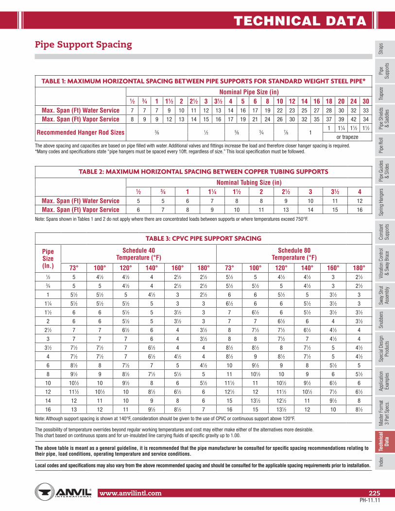
TECHNICAL DATA
Stra
psSp
ring
Hang
ers
Cons
tant
Supp
orts
Vibr
ation
Con
trol
& Sw
ay B
race
Sway
Stru
tAs
sem
bly
Snub
bers
Appl
icatio
nEx
ampl
esSp
ecial
Des
ign
Prod
ucts
Trap
eze
Pipe
Rol
lPi
pe G
uide
s&
Slid
esPi
pe S
hield
s&
Sadd
lesPi
peSu
ppor
tsIn
dex
www.anvilintl.com 225
Tech
nica
lDa
taM
aster
For
mat
3 Pa
rt Sp
ecs.
TABLE 2: MAXIMUM HORIZONTAL SPACING BETWEEN COPPER TUBING SUPPORTS
Nominal Tubing Size (in)1⁄2 3⁄4 1 11⁄4 11⁄2 2 21⁄2 3 31⁄2 4
Max. Span (Ft) Water Service 5 5 6 7 8 8 9 10 11 12
Max. Span (Ft) Vapor Service 6 7 8 9 10 11 13 14 15 16
Note: Spans shown in Tables 1 and 2 do not apply where there are concentrated loads between supports or where temperatures exceed 750°F.
TABLE 1: MAXIMUM HORIZONTAL SPACING BETWEEN PIPE SUPPORTS FOR STANDARD WEIGHT STEEL PIPE*
Nominal Pipe Size (in)1⁄2 3⁄4 1 11⁄2 2 21⁄2 3 31⁄2 4 5 6 8 10 12 14 16 18 20 24 30
Max. Span (Ft) Water Service 7 7 7 9 10 11 12 13 14 16 17 19 22 23 25 27 28 30 32 33
Max. Span (Ft) Vapor Service 8 9 9 12 13 14 15 16 17 19 21 24 26 30 32 35 37 39 42 34
Recommended Hanger Rod Sizes 3⁄8 1⁄2 5⁄8 3⁄4 7⁄8 11 11⁄4 11⁄2 11⁄2
or trapeze
The above spacing and capacities are based on pipe filled with water. Additional valves and fittings increase the load and therefore closer hanger spacing is required. *Many codes and specifications state “pipe hangers must be spaced every 10ft. regardless of size.” This local specification must be followed.
Pipe Support Spacing
TABLE 3: CPVC PIPE SUPPORT SPACING
Pipe Size (In.)
Schedule 40 Temperature (°F)
Schedule 80 Temperature (°F)
73° 100° 120° 140° 160° 180° 73° 100° 120° 140° 160° 180°1⁄2 5 41⁄2 41⁄2 4 21⁄2 21⁄2 51⁄2 5 41⁄2 41⁄2 3 21⁄23⁄4 5 5 41⁄2 4 21⁄2 21⁄2 51⁄2 51⁄2 5 41⁄2 3 21⁄2
1 51⁄2 51⁄2 5 41⁄2 3 21⁄2 6 6 51⁄2 5 31⁄2 3
11⁄4 51⁄2 51⁄2 51⁄2 5 3 3 61⁄2 6 6 51⁄2 31⁄2 3
11⁄2 6 6 51⁄2 5 31⁄2 3 7 61⁄2 6 51⁄2 31⁄2 31⁄2
2 6 6 51⁄2 5 31⁄2 3 7 7 61⁄2 6 4 31⁄2
21⁄2 7 7 61⁄2 6 4 31⁄2 8 71⁄2 71⁄2 61⁄2 41⁄2 4
3 7 7 7 6 4 31⁄2 8 8 71⁄2 7 41⁄2 4
31⁄2 71⁄2 71⁄2 7 61⁄2 4 4 81⁄2 81⁄2 8 71⁄2 5 41⁄2
4 71⁄2 71⁄2 7 61⁄2 41⁄2 4 81⁄2 9 81⁄2 71⁄2 5 41⁄2
6 81⁄2 8 71⁄2 7 5 41⁄2 10 91⁄2 9 8 51⁄2 5
8 91⁄2 9 81⁄2 71⁄2 51⁄2 5 11 101⁄2 10 9 6 51⁄2
10 101⁄2 10 91⁄2 8 6 51⁄2 111⁄2 11 101⁄2 91⁄2 61⁄2 6
12 111⁄2 101⁄2 10 81⁄2 61⁄2 6 121⁄2 12 111⁄2 101⁄2 71⁄2 61⁄2
14 12 11 10 9 8 6 15 131⁄2 121⁄2 11 91⁄2 8
16 13 12 11 91⁄2 81⁄2 7 16 15 131⁄2 12 10 81⁄2
Note: Although support spacing is shown at 140°F, consideration should be given to the use of CPVC or continuous support above 120°F.
The possibility of temperature overrides beyond regular working temperatures and cost may either make either of the alternatives more desirable. This chart based on continuous spans and for un-insulated line carrying fluids of specific gravity up to 1.00.
The above table is meant as a general guideline, it is recommended that the pipe manufacturer be consulted for specific spacing recommendations relating to their pipe, load conditions, operating temperature and service conditions.
Local codes and specifications may also vary from the above recommended spacing and should be consulted for the applicable spacing requirements prior to installation.
PH-11.11

TECHNICAL DATA
www.anvilintl.com226
Pipe Support Spacing – PVC
Pipe Size (In.)
Schedule 40 Temperature (°F)
Schedule 80 Temperature (°F)
Schedule 120 Temperature (°F)
60 80 100 120 140 60 80 100 120 140 60 80 100 120 1401⁄4 4 31⁄2 31⁄2 2 2 4 4 31⁄2 21⁄2 2 – – – – –
3⁄8 4 4 31⁄2 21⁄2 2 41⁄2 41⁄2 4 21⁄2 21⁄2 – – – – –
1⁄2 41⁄2 41⁄2 4 21⁄2 21⁄2 5 41⁄2 41⁄2 3 21⁄2 5 5 41⁄2 3 21⁄2
3⁄4 5 41⁄2 4 21⁄2 21⁄2 51⁄2 5 41⁄2 3 21⁄2 51⁄2 5 41⁄2 3 3
1 51⁄2 5 41⁄2 3 21⁄2 6 51⁄2 5 31⁄2 3 6 51⁄2 5 31⁄2 3
11⁄4 51⁄2 51⁄2 5 3 3 6 6 51⁄2 31⁄2 3 61⁄2 6 51⁄2 31⁄2 31⁄2
11⁄2 6 51⁄2 5 31⁄2 3 61⁄2 6 51⁄2 31⁄2 31⁄2 61⁄2 61⁄2 6 4 31⁄2
2 6 51⁄2 5 31⁄2 3 7 61⁄2 6 4 31⁄2 71⁄2 7 61⁄2 4 31⁄2
21⁄2 7 61⁄2 6 4 31⁄2 71⁄2 71⁄2 61⁄2 41⁄2 4 8 71⁄2 7 41⁄2 4
3 7 7 6 4 31⁄2 8 71⁄2 7 41⁄2 4 81⁄2 8 71⁄2 5 41⁄2
31⁄2 71⁄2 7 61⁄2 4 4 81⁄2 8 71⁄2 5 41⁄2 9 81⁄2 71⁄2 5 41⁄2
4 71⁄2 7 61⁄2 41⁄2 4 9 81⁄2 71⁄2 5 41⁄2 91⁄2 9 81⁄2 51⁄2 5
5 8 71⁄2 7 41⁄2 4 91⁄2 9 8 51⁄2 5 101⁄2 10 9 6 51⁄2
6 81⁄2 8 71⁄2 5 41⁄2 10 91⁄2 9 6 5 111⁄2 101⁄2 91⁄2 61⁄2 6
8 9 81⁄2 8 5 41⁄2 11 101⁄2 91⁄2 61⁄2 51⁄2 – – – – –
10 10 9 81⁄2 51⁄2 5 12 11 10 7 6 – – – – –
12 111⁄2 101⁄2 91⁄2 61⁄2 51⁄2 13 12 101⁄2 71⁄2 61⁄2 – – – – –
14 12 11 10 7 6 131⁄2 13 11 8 7 – – – – –
16 121⁄2 111⁄2 101⁄2 71⁄2 61⁄2 14 131⁄2 111⁄2 81⁄2 71⁄2 – – – – –
18 13 12 11 8 7 141⁄2 14 12 11 9 – – – – –
20 14 121⁄2 111⁄2 10 81⁄2 151⁄2 141⁄2 121⁄2 111⁄2 91⁄2 – – – – –
24 15 13 121⁄2 11 91⁄2 17 15 14 121⁄2 101⁄2 – – – – –
SDR 41 SDR 26 –
18 13 12 11 8 7 141⁄2 14 12 9 8 – – – – –
20 131⁄2 121⁄2 111⁄2 81⁄2 71⁄2 15 141⁄2 121⁄2 91⁄2 81⁄2 – – – – –
24 14 13 12 9 8 151⁄2 15 13 10 9 – – – – –
Note: Although support spacing is shown at 140°F, consideration should be given to the use of CPVC or continuous support above 120°F.
The possibility of temperature overrides beyond regular working temperatures and cost may either make either of the alternatives more desirable. This chart based on continuous spans and for un-insulated line carrying fluids of specific gravity up to 1.00.
The above table is meant as a general guideline, it is recommended that the pipe manufacturer be consulted for specific spacing recommendations relating to their pipe, load conditions, operating temperature and service conditions.
Local codes and specifications may also vary from the above recommended spacing and should be consulted for the applicable spacing requirements prior to installation.
PH-11.11

TECHNICAL DATA
Stra
psSp
ring
Hang
ers
Cons
tant
Supp
orts
Vibr
ation
Con
trol
& Sw
ay B
race
Sway
Stru
tAs
sem
bly
Snub
bers
Appl
icatio
nEx
ampl
esSp
ecial
Des
ign
Prod
ucts
Trap
eze
Pipe
Rol
lPi
pe G
uide
s&
Slid
esPi
pe S
hield
s&
Sadd
lesPi
peSu
ppor
tsIn
dex
www.anvilintl.com 227
Tech
nica
lDa
taM
aster
For
mat
3 Pa
rt Sp
ecs.
Pipe Data – Steel Schedule No. 40 & 80
Pipe Size O.D. Schedule No. Wall Thickness Weight per Foot (lbs)
Weight of Water per Foot (lbs)
3⁄8 0.67540 0.091 0.568 0.08380 0.126 0.739 0.061
1⁄2 0.84040 0.109 0.851 0.13280 0.147 1.088 0.101
3⁄4 1.05040 0.113 1.131 0.23080 0.154 1.474 0.188
1 1.31540 0.133 1.679 0.37480 0.179 2.172 0.311
11⁄4 1.66040 0.140 2.273 0.64880 0.191 2.997 0.555
11⁄2 1.90040 0.145 2.718 0.88280 0.200 3.631 0.765
2 2.37540 0.154 3.653 1.45580 0.218 5.022 1.280
21⁄2 2.87540 0.203 5.793 2.07680 0.276 7.661 1.837
3 3.50040 0.216 7.580 3.2080 0.300 10.25 2.864
31⁄2 4.00040 0.226 9.11 4.28080 0.318 12.51 3.850
4 4.50040 0.237 10.79 5.51080 0.337 14.98 4.980
5 5.56340 0.258 14.62 8.66080 0.375 20.78 7.870
6 6.62540 0.280 18.97 12.5180 0.432 28.57 11.29
8 8.62540 0.322 28.55 21.6980 0.500 43.39 19.800
10 10.7540 0.365 40.48 34.1080 0.593 64.33 31.10
12 12.7540 0.406 53.53 48.5080 0.687 88.51 44.00
14 14.00040 0.437 63.37 58.7080 0.750 106.13 53.20
16 16.00040 0.500 82.77 76.5080 0.843 136.46 69.70
18 18.00040 0.562 104.75 97.0080 0.937 170.75 88.50
20 20.00040 0.593 122.91 120.480 1.031 208.87 109.4
24 24.00040 0.687 171.17 174.380 1.218 296.36 158.3
30 30.000 20 0.500 158.00 286.236 36.000 20 0.500 190.00 417.1
PH-11.11
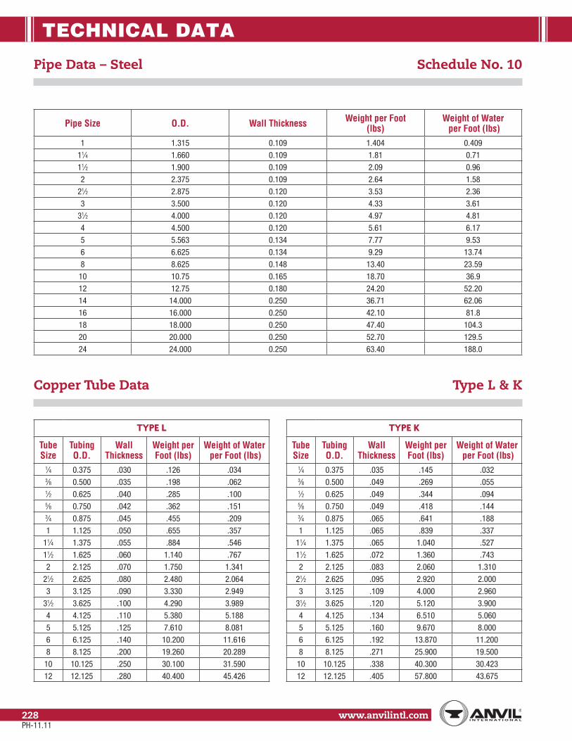
TECHNICAL DATA
www.anvilintl.com228
Pipe Data – Steel Schedule No. 10
Pipe Size O.D. Wall Thickness Weight per Foot (lbs)
Weight of Water per Foot (lbs)
1 1.315 0.109 1.404 0.409
11⁄4 1.660 0.109 1.81 0.71
11⁄2 1.900 0.109 2.09 0.96
2 2.375 0.109 2.64 1.58
21⁄2 2.875 0.120 3.53 2.36
3 3.500 0.120 4.33 3.61
31⁄2 4.000 0.120 4.97 4.81
4 4.500 0.120 5.61 6.17
5 5.563 0.134 7.77 9.53
6 6.625 0.134 9.29 13.74
8 8.625 0.148 13.40 23.59
10 10.75 0.165 18.70 36.9
12 12.75 0.180 24.20 52.20
14 14.000 0.250 36.71 62.06
16 16.000 0.250 42.10 81.8
18 18.000 0.250 47.40 104.3
20 20.000 0.250 52.70 129.5
24 24.000 0.250 63.40 188.0
Copper Tube Data Type L & K
TYPE L
Tube Size
Tubing O.D.
Wall Thickness
Weight per Foot (lbs)
Weight of Water per Foot (lbs)
1⁄4 0.375 .030 .126 .0343⁄8 0.500 .035 .198 .0621⁄2 0.625 .040 .285 .1005⁄8 0.750 .042 .362 .1513⁄4 0.875 .045 .455 .209
1 1.125 .050 .655 .357
11⁄4 1.375 .055 .884 .546
11⁄2 1.625 .060 1.140 .767
2 2.125 .070 1.750 1.341
21⁄2 2.625 .080 2.480 2.064
3 3.125 .090 3.330 2.949
31⁄2 3.625 .100 4.290 3.989
4 4.125 .110 5.380 5.188
5 5.125 .125 7.610 8.081
6 6.125 .140 10.200 11.616
8 8.125 .200 19.260 20.289
10 10.125 .250 30.100 31.590
12 12.125 .280 40.400 45.426
TYPE K
Tube Size
Tubing O.D.
Wall Thickness
Weight per Foot (lbs)
Weight of Water per Foot (lbs)
1⁄4 0.375 .035 .145 .0323⁄8 0.500 .049 .269 .0551⁄2 0.625 .049 .344 .0945⁄8 0.750 .049 .418 .1443⁄4 0.875 .065 .641 .188
1 1.125 .065 .839 .337
11⁄4 1.375 .065 1.040 .527
11⁄2 1.625 .072 1.360 .743
2 2.125 .083 2.060 1.310
21⁄2 2.625 .095 2.920 2.000
3 3.125 .109 4.000 2.960
31⁄2 3.625 .120 5.120 3.900
4 4.125 .134 6.510 5.060
5 5.125 .160 9.670 8.000
6 6.125 .192 13.870 11.200
8 8.125 .271 25.900 19.500
10 10.125 .338 40.300 30.423
12 12.125 .405 57.800 43.675
PH-11.11

TECHNICAL DATA
Stra
psSp
ring
Hang
ers
Cons
tant
Supp
orts
Vibr
ation
Con
trol
& Sw
ay B
race
Sway
Stru
tAs
sem
bly
Snub
bers
Appl
icatio
nEx
ampl
esSp
ecial
Des
ign
Prod
ucts
Trap
eze
Pipe
Rol
lPi
pe G
uide
s&
Slid
esPi
pe S
hield
s&
Sadd
lesPi
peSu
ppor
tsIn
dex
www.anvilintl.com 229
Tech
nica
lDa
taM
aster
For
mat
3 Pa
rt Sp
ecs.
Nom.Pipe Size
Class O.D.D.I. Pipe
Wall Thickness
Weightper Foot
(lbs)
Weight ofWater per Foot
(lbs)
3 53 3.96 .31 11.20 3.80
4 53 4.80 .32 14.20 5.90
6 53 6.90 .34 22.00 13.10
8 53 9.05 .36 31.00 23.00
10 53 11.10 .38 40.40 36.40
12 53 13.20 .40 50.70 52.30
14 53 15.30 .42 62.40 71.10
16 53 17.40 .43 72.80 93.10
18 53 19.50 .44 83.60 117.90
20 53 21.60 .45 95.20 145.80
24 53 25.80 .47 119.20 210.20
30 53 32.00 .51 161.30 326.50
36 53 38.30 .58 219.50 469.30
42 53 44.50 .65 285.20 634.90
48 53 50.80 .72 360.30 828.90
AWWA Ductile Iron Pipe Data Soil Pipe Data
SERVICE WEIGHT CAST IRON (BELL & SPIGOT TYPE)
Nom. Pipe Size
O.D. of Cast Iron
Pipe
Wall Thickness
Weightper Foot
(lbs)
Weight of Water per Foot
(lbs)
2 2.25 .17 4.00 1.50
3 3.25 .17 6.00 3.40
4 4.25 .18 8.00 6.20
5 5.25 .18 10.40 12.30
6 6.25 .18 13.00 13.90
8 8.38 .23 20.00 25.70
10 10.50 .28 29.00 40.60
12 12.50 .28 38.00 58.20
15 15.62 .31 51.00 96.60
EXTRA WEIGHT CAST IRON (BELL & SPIGOT TYPE)
Nom. Pipe Size
O.D. of Cast Iron
Pipe
Wall Thickness
Weightper Foot
(lbs)
Weight of Water per Foot
(lbs)
2 2.38 .190 5.00 1.60
3 3.50 .250 9.00 3.70
4 4.50 .250 12.00 6.50
5 5.50 .250 15.00 10.20
6 6.50 .250 19.00 14.70
8 8.62 .310 30.00 26.10
10 10.75 .375 43.00 40.80
12 12.75 .375 54.00 58.80
15 15.88 .440 75.00 91.80
NO-HUB CAST IRON
Nom. Pipe Size
O.D. of Cast Iron
Pipe
Wall Thickness
Weightper Foot
(lbs)
Weight of Water per Foot
(lbs)
11⁄2 1.90 .16 2.70 3.50
2 2.35 .16 3.60 5.00
3 3.35 .16 5.20 8.30
4 4.38 .19 7.40 12.80
5 5.30 .19 9.60 17.90
6 6.30 .19 11.00 23.00
8 8.38 .23 18.00 39.50
10 10.50 .28 26.20 43.34
12 12.50 .28 35.50 62.51
PH-11.11

TECHNICAL DATA
www.anvilintl.com230
PVC Plastic Pipe Data Schedule No. 40 & 80
Pipe Size O.D. Schedule No. Wall Thickness Weight per Foot (lbs)
Weight of Water per Foot (lbs)
1⁄8 0.40540 0.068 0.043 0.02580 0.095 0.055 0.016
1⁄4 0.54040 0.088 0.074 0.04580 0.119 0.094 0.031
3⁄8 0.67540 0.091 0.100 0.08380 0.126 0.129 0.061
1⁄2 0.84040 0.109 0.150 0.13280 0.147 0.150 0.101
3⁄4 1.05040 0.113 0.199 0.23080 0.154 0.259 0.186
1 1.31540 0.133 0.295 0.37480 0.179 0.382 0.311
11⁄4 1.66040 0.140 0.400 0.64780 0.191 0.527 0.555
11⁄2 1.90040 0.145 0.478 0.88280 0.200 0.639 0.765
2 2.37540 0.154 0.643 1.45280 0.218 0.884 1.279
21⁄2 2.87540 0.203 1.020 2.07280 0.276 1.350 1.834
3 3.50040 0.216 1.333 3.20080 0.300 1.804 2.860
31⁄2 4.00040 0.226 1.598 4.28080 0.318 2.195 3.850
4 4.50040 0.237 1.899 5.51080 0.337 2.636 4.980
5 5.56340 0.258 2.770 8.66080 0.375 4.126 7.870
6 6.62540 0.280 3.339 12.15080 0.432 5.028 11.290
8 8.62540 0.322 5.280 21.60080 0.500 8.023 19.800
10 10.75040 0.366 7.505 34.10080 0.593 11.894 31.100
12 12.75040 0.406 10.023 48.50080 0.687 16.365 44.000
PH-11.11

TECHNICAL DATA
Stra
psSp
ring
Hang
ers
Cons
tant
Supp
orts
Vibr
ation
Con
trol
& Sw
ay B
race
Sway
Stru
tAs
sem
bly
Snub
bers
Appl
icatio
nEx
ampl
esSp
ecial
Des
ign
Prod
ucts
Trap
eze
Pipe
Rol
lPi
pe G
uide
s&
Slid
esPi
pe S
hield
s&
Sadd
lesPi
peSu
ppor
tsIn
dex
www.anvilintl.com 231
Tech
nica
lDa
taM
aster
For
mat
3 Pa
rt Sp
ecs.
Thermal Expansion of Pipe Material
THERMAL EXPANSION OF PIPE MATERIAL – (IN/FT)
Temp ˚FCarbon Steel - Low Chrome Steel (thru 3% Cr)
0 10 20 30 40 50 60 70 80 90-200 -0.0180 -0.0187 -0.0192 -0.0198 -0.0203 -0.0209 -0.0215 -0.0220 -0.0225 -0.0230-100 -0.0121 -0.0127 -0.0133 -0.0140 -0.0146 -0.0152 -0.0158 -0.0163 -0.0169 -0.0174
0 -0.0051 -0.0058 -0.0065 -0.0073 -0.0080 -0.0087 -0.0096 -0.0103 -0.0109 -0.01160 -0.0051 -0.0044 -0.0037 -0.0029 -0.0022 -0.0015 -0.0007 0 0.0008 0.0015
100 0.0023 0.0030 0.0038 0.0046 0.0053 0.0061 0.0068 0.0076 0.0084 0.0091200 0.0099 0.0107 0.0116 0.0124 0.0132 0.0141 0.0149 0.0157 0.0165 0.0174300 0.0182 0.0191 0.0200 0.0208 0.0217 0.0226 0.0235 0.0244 0.0252 0.0261400 0.0270 0.0279 0.0288 0.0298 0.0307 0.0316 0.0325 0.0334 0.0344 0.0353500 0.0362 0.0372 0.0382 0.0391 0.0401 0.0411 0.0421 0.0431 0.0440 0.0450600 0.0460 0.0470 0.0481 0.0491 0.0501 0.0512 0.0522 0.0532 0.0542 0.0553700 0.0563 0.0574 0.0584 0.0595 0.0606 0.0617 0.0627 0.0638 0.0649 0.0659800 0.0670 0.0681 0.0692 0.0703 0.0714 0.0726 0.0737 0.0748 0.0759 0.0770900 0.0781 0.0792 0.0803 0.0813 0.0824 0.0835 0.0846 0.0857 0.0867 0.0878
1,000 0.0889 0.0901 0.0912 0.0924 0.0935 0.0946 0.0958 0.0970 0.0981 0.09931,100 0.1004 0.1015 0.1025 0.1036 0.1046 0.1057 0.1068 0.1078 0.1089 0.10991,200 0.1110 0.1121 0.1132 0.1144 0.1155 0.1166 0.1177 0.1188 0.1200 0.12111,300 0.1222 0.1233 0.1244 0.1256 0.1267 0.1278 0.1299 0.1320 0.1342 0.13631,400 0.1334 – – – – – – – – –
THERMAL EXPANSION OF PIPE MATERIAL – (IN/FT)
Temp ˚FAustenitic Stainless Steels (304, 316, 347)
0 10 20 30 40 50 60 70 80 90-200 -0.0281 -0.0295 -0.0305 -0.0314 -0.0324 -0.0334 -0.0343 -0.0353 -0.0362 -0.0372-100 -0.0187 -0.0197 -0.0207 -0.0216 -0.0226 -0.0236 -0.0245 -0.0254 -0.0263 -0.0272
0 -0.0078 -0.0089 -0.0100 -0.0112 -0.0123 -0.0134 -0.0145 -0.0155 -0.0166 -0.01760 -0.0078 -0.0067 -0.0056 -0.0044 -0.0033 -0.0022 -0.0011 0 0.0012 0.0023
100 0.0034 0.0045 0.0056 0.0068 0.0079 0.0090 0.0101 0.0112 0.0124 0.0135200 0.0146 0.0158 0.0169 0.0181 0.0192 0.0203 0.0215 0.0227 0.0238 0.0250300 0.0261 0.0273 0.0285 0.0297 0.0309 0.0321 0.0332 0.0344 0.0356 0.0368400 0.0380 0.0392 0.0404 0.0416 0.0428 0.0440 0.0453 0.0465 0.0477 0.0489500 0.0501 0.0513 0.0526 0.0538 0.0550 0.0562 0.0575 0.0587 0.0599 0.0612600 0.0624 0.0637 0.0649 0.0662 0.0674 0.0687 0.0700 0.0712 0.0725 0.0737700 0.0750 0.0763 0.0776 0.0789 0.0802 0.0815 0.0828 0.0841 0.0854 0.0867800 0.0880 0.0893 0.0906 0.0920 0.0933 0.0946 0.0959 0.0972 0.0986 0.0999900 0.1012 0.1260 0.1039 0.1053 0.1066 0.1080 0.1094 0.1107 0.1121 0.1134
1,000 0.1148 0.1162 0.1175 0.1189 0.1202 0.1216 0.1229 0.1243 0.1257 0.12701,100 0.1284 0.1298 0.1311 0.1325 0.1338 0.1352 0.1366 0.1379 0.1393 0.14061,200 0.1420 0.1434 0.1447 0.1461 0.1474 0.1488 0.1502 0.1515 0.1529 0.15421,300 0.1556 0.1570 0.1583 0.1597 0.1610 0.1624 0.1638 0.1651 0.1665 0.16781,400 0.1692 0.1704 0.1717 0.1731 0.1744 0.1757 0.1771 0.1784 0.1796 0.1811
Note: Intersect “10” Degree increments across the top of each table with the “100” degree increments down the left side to determine the coefficient of thermal expansion for the desired temperature.
PH-11.11

TECHNICAL DATA
www.anvilintl.com232
Thermal Expansion of Pipe Material
THERMAL EXPANSION OF PIPE MATERIAL – (IN/FT)
Temp ˚F Intermediate Alloy Steels(5% thru 9% Cr Mo) Copper Brass Aluminum
-200 – -0.0275 -0.2870 -0.0373-150 – -0.0231 -0.0241 -0.0310-100 – -0.1830 -0.1900 -0.0244-50 – -0.1320 -0.0137 -0.01760 – -0.0790 -0.0081 -0.010450 – -0.0022 -0.0023 -0.003070 0.0000 0.0000 0.0000 0.0000100 0.0022 0.0034 0.0035 0.0046150 0.0058 0.0091 0.0093 0.0123200 0.0094 0.0151 0.0152 0.0200250 0.0132 0.0208 0.0214 0.0283300 0.0171 0.0267 0.0276 0.0366350 0.0210 0.0327 0.0340 0.0452400 0.0250 0.0388 0.0405 0.0539450 0.0292 0.0449 0.0472 0.0628500 0.0335 0.0512 0.0540 0.0717550 0.0379 0.0574 0.0610 0.0810600 0.0424 0.0639 0.0680 0.0903650 0.0469 0.0703 0.0753 –700 0.0514 0.0768 0.0826 –750 0.0562 0.0834 0.0902 –800 0.0610 0.0900 0.0978 –850 0.0658 0.0967 0.1056 –900 0.0707 0.1037 0.1135 –950 0.0756 0.1105 0.1216 –
1,000 0.0806 0.1175 0.1298 –1,050 0.0855 – – –1,100 0.0905 – – –1,150 0.0952 – – –1,200 0.1000 – – –1,250 0.1053 – – –1,300 0.1106 – – –1,350 0.1155 – – –1,400 0.1205 – – –
PH-11.11

TECHNICAL DATA
Stra
psSp
ring
Hang
ers
Cons
tant
Supp
orts
Vibr
ation
Con
trol
& Sw
ay B
race
Sway
Stru
tAs
sem
bly
Snub
bers
Appl
icatio
nEx
ampl
esSp
ecial
Des
ign
Prod
ucts
Trap
eze
Pipe
Rol
lPi
pe G
uide
s&
Slid
esPi
pe S
hield
s&
Sadd
lesPi
peSu
ppor
tsIn
dex
www.anvilintl.com 233
Tech
nica
lDa
taM
aster
For
mat
3 Pa
rt Sp
ecs.
Maximum Recommended Applied Torques
FOR SET SCREWS IN MSS TYPE 19 & 23 C-CLAMP
Thread Size Torque Value (in.- lbs)
1⁄4 403⁄8 601⁄2 1255⁄8 2503⁄4 4007⁄8 665
Extracted from MSS-SP-69
FOR FIG. 261 & CT-121 RISER CLAMPS
Bolt Size Torque Value (ft.- lbs)
1⁄4 65⁄16 113⁄8 217⁄16 321⁄2 465⁄8 1003⁄4 1507⁄8 190
1 280
Bolts per ASTM A307Nuts per ASTM A563
LOAD CARRYING CAPACITIES OF THREADED HANGER RODS.MATERIALS CARBON STEEL WITH MINIMUM ACTUAL TENSILE STRENGTH OF 50 KSI.
Rod Diameter (in)
Threads per Inch
Root Area of Coarse Thread (in2)
Maximum Safe Load (lbs) Rod Temperature, 650° F
Maximum Safe Load (lbs) Rod Temperature, 750° F
3⁄8 16 UNC 0.0678 730 5721⁄2 13 UNC 0.126 1,350 1,0575⁄8 11 UNC 0.202 2,160 1,6923⁄4 10 UNC 0.302 3,230 2,5307⁄8 9 UNC 0.419 4,480 3,508
1 8 UNC 0.551 5,900 4,620
11⁄4 7 UNC 0.890 9,500 7,440
11⁄2 6 UNC 1.29 13,800 10,807
13⁄4 5 UNC 1.74 18,600 14,566
2 41⁄2 UNC 2.30 24,600 19,265
21⁄4 41⁄2 UNC 3.02 32,300 25,295
21⁄2 4 UNC 3.72 39,800 31,169
23⁄4 4 UNC 4.62 49,400 38,687
3 4 UNC 5.62 60,100 47,066
31⁄4 4 UNC 6.72 71,900 56,307
31⁄2 4 UNC 7.92 84,700 66,331
33⁄4 4 UNC 9.21 98,500 77,139
4 4 UNC 10.6 114,000 88,807
41⁄4 4 UN 12.1 129,000 101,337
41⁄2 4 UN 13.7 146,000 114,807
43⁄4 4 UN 15.4 165,000 128,982
5 4 UN 17.2 184,000 144,096
Standard UNC thread thru 4" diameter and 4-UN-2A thread series for 41⁄4" diameter and larger
Threaded Rod Data
PH-11.11

ANVIL COMPLIANCES, LISTINGS AND APPROVALSTECHNICAL DATA
www.anvilintl.com234
Beam Dimensions
W SHAPES
Depth of Section
Y
Weight per Ft.,
lb.
Flange Width
Mean Thick of Flange
Z
14
99 145⁄8 0.780109 145⁄8 0.860120 145⁄8 0.940132 143⁄4 1.030
16
36 7 0.43040 7 0.50545 7 0.56550 71⁄8 0.6357 71⁄8 0.71567 101⁄4 0.66577 101⁄4 0.76089 103⁄8 0.875
100 103⁄8 0.985
18
50 71⁄2 0.57055 71⁄2 0.63060 71⁄2 0.69565 75⁄8 0.75071 75⁄8 0.81076 11 0.68086 111⁄8 0.77097 111⁄8 0.870
106 111⁄4 0.940
21
62 81⁄4 0.61568 81⁄4 0.68573 81⁄4 0.74083 83⁄8 0.83593 83⁄8 0.930
101 121⁄4 0.800111 123⁄8 0.875122 123⁄8 0.960
24
76 9 0.68084 9 0.77094 91⁄8 0.875
104 123⁄4 0.750117 123⁄4 0.850131 127⁄8 0.960
27
94 10 0.745102 10 0.830114 101⁄8 0.930146 14 0.975
30
108 101⁄2 0.760116 101⁄2 0.850124 101⁄2 0.930132 101⁄2 1.000
33118 111⁄2 0.740130 111⁄2 0.855141 111⁄2 0.960
36135 12 0.790150 12 0.940160 12 1.020
W SHAPES
Depth of Section
Y
Weight per Ft.,
lb.
Flange Width
Mean Thick of Flange
Z
5 19 5 0.4306 25 61⁄8 0.455
8
18 51⁄4 0.33021 51⁄4 0.40024 61⁄2 0.40028 61⁄2 0.46531 8 0.43535 8 0.49540 81⁄8 0.56048 81⁄8 0.68558 81⁄4 0.81067 81⁄4 0.935
10
22 53⁄4 0.36026 53⁄4 0.44030 53⁄4 0.51033 8 0.43539 8 0.53045 8 0.62049 10 0.56054 10 0.61560 101⁄8 0.68068 101⁄8 0.77077 101⁄4 0.87088 101⁄4 0.990
12
26 61⁄2 0.38030 61⁄2 0.44035 61⁄2 0.52040 8 0.51545 8 0.57550 81⁄8 0.64053 10 0.57558 10 0.64065 12 0.60572 12 0.67079 121⁄8 0.73587 121⁄8 0.81096 121⁄8 0.900
106 121⁄4 0.990
14
30 63⁄4 0.38534 63⁄4 0.45538 63⁄4 0.51543 8 0.53048 8 0.59553 8 0.66061 10 0.64568 10 0.72074 101⁄8 0.78582 101⁄8 0.85590 141⁄2 0.710
S SHAPES
Depth of Section
Y
Weight per Ft.,
lb.
Flange Width
Mean Thick of Flange
Z
35.7 23⁄8
0.2507.5 21⁄2
47.7 25⁄8
0.3139.5 23⁄4
510.0 3
0.31314.75 31⁄4
612.5 33⁄8
0.37517.25 35⁄8
715.3 35⁄8
0.37520.0 37⁄8
818.4 4
0.43823.0 41⁄8
1025.4 45⁄8
0.50035.0 5
12
31.8 50.563
35.0 51⁄840.8 51⁄4
0.68850.0 51⁄2
1542.9 51⁄2
0.62550.0 55⁄8
1854.7 6
0.68870.0 61⁄4
2066.0 61⁄4
0.81375.0 63⁄8
20.386.0 7
0.93896.0 71⁄4
2480.0 7
0.87590.0 71⁄8100.0 71⁄4
AMERICAN STANDARD CHANNELS
Depth of Section
Y
Weight per Ft.,
lb.
Flange Width
Mean Thick of Flange
Z
34.1 13⁄8
0.2505.0 11⁄26.0 15⁄8
45.4 15⁄8
0.3137.25 13⁄4
56.7 13⁄4
0.3139.0 17⁄8
68.2 17⁄8
0.37510.5 213.0 21⁄8
79.8 21⁄8
0.37512.25 21⁄414.75 21⁄4
811.5 21⁄4
0.37513.75 23⁄818.75 21⁄2
913.4 23⁄8
0.43815.0 21⁄220.0 25⁄8
10
15.3 25⁄8
0.43820.0 23⁄425.0 27⁄830.0 3
1220.7 3
0.50025.0 330.0 31⁄8
1533.9 33⁄8
0.62540.0 31⁄250.0 33⁄4
18
42.7 4
0.62545.8 451.9 41⁄858.0 41⁄4
Y Z Y Z Y Z
PH-11.11
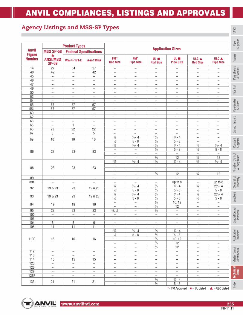
ANVIL COMPLIANCES, LISTINGS AND APPROVALS
Stra
psSp
ring
Hang
ers
Cons
tant
Supp
orts
Vibr
ation
Con
trol
& Sw
ay B
race
Sway
Stru
tAs
sem
bly
Snub
bers
Appl
icatio
nEx
ampl
esSp
ecial
Des
ign
Prod
ucts
Trap
eze
Pipe
Rol
lPi
pe G
uide
s&
Slid
esPi
pe S
hield
s&
Sadd
lesPi
peSu
ppor
tsIn
dex
www.anvilintl.com 235
Tech
nica
lDa
taM
aster
For
mat
3 Pa
rt Sp
ecs.
Anvil Figure
Number
Product TypesApplication Sizes
MSS SP-58 &
ANSI/MSS SP-69
Federal Specifications
WW-H-171-E A-A-1192A FM* Rod Size
FM* Pipe Size
UL ■ Rod Size
UL ■ Pipe Size
ULC ▲ Rod Size
ULC ▲ Pipe Size
14 27 54 27 – – – – – –40 42 – 42 – – – – – –45 – – – – – – – – –46 – – – – – – – – –47 – – – – – – – – –49 – – – – – – – – –50 – – – – – – – – –52 – – – – – – – – –54 – – – – – – – – –55 57 57 57 – – – – – –55L 57 57 57 – – – – – –60 – – – – – – – – –62 – – – – – – – – –63 – – – – – – – – –65 – 1 – – – – – – –66 22 22 22 – – – – – –67 5 – 5 – – – – – –
69 10 10 103⁄8 3⁄4 - 4 3⁄8 3⁄4 - 4 – –1⁄2 5 - 8 1⁄2 5 - 8 – –
86 23 23 23
3⁄8 3⁄4 - 4 3⁄8 3⁄4 - 4 3⁄8 3⁄4 - 4– – 1⁄2 5 - 8 1⁄2 5 - 8– – – – – –– – 3⁄4 12 3⁄4 12
88 23 23 23
3⁄8 3⁄4 - 4 3⁄8 3⁄4 - 4 3⁄8 3⁄4 - 4– – – – – –– – – – – –– – 3⁄4 12 3⁄4 12
89 – – – – – – – – –89X – – – – – – up to 8 – up to 8
92 19 & 23 23 19 & 233⁄8 3⁄4 - 4 3⁄8 3⁄4 - 4 3⁄8 21⁄2 - 41⁄2 5 - 8 1⁄2 5 - 8 1⁄2 5 - 8
93 19 & 23 23 19 & 233⁄8 3⁄4 - 4 3⁄8 3⁄4- 4 3⁄8 21⁄2 - 41⁄2 5 - 8 1⁄2 5 - 8 1⁄2 5 - 8
94 19 19 19 – – 5⁄8 10, 12 – –– – 3⁄4 12 – –
95 23 23 23 3⁄8, 1⁄2 – 3⁄8 – – –100 – – – – – – – – –103 – – – – – – – – –104 6 6 6 – – – – – –108 11 11 11 – – – – – –
110R 16 16 16
3⁄8 3⁄4 - 4 3⁄8 3⁄4 - 4 – –1⁄2 5 - 8 1⁄2 5 - 8 – –– – 5⁄8 10, 12 – –– – 3⁄4 12 – –– – 7⁄8 12 – –
112 – – – – – – – – –113 – – – – – – – – –114 15 15 15 – – – – – –120 – – – – – – – – –126 – – – – – – – – –127 – – – – – – – – –
128R – – – – – – – – –
133 21 21 21 – – 3⁄8 3⁄4 - 4 – –– – 1⁄2 5 - 8 – –
*= FM Approved ■ = UL Listed ▲ = ULC Listed
Agency Listings and MSS-SP Types
PH-11.11

ANVIL COMPLIANCES, LISTINGS AND APPROVALS
www.anvilintl.com236
Agency Listings and MSS-SP Types (cont.)
Anvil Figure
Number
Product TypesApplication Sizes
MSS SP-58 &
ANSI/MSS SP-69
Federal Specifications
WW-H-171-E A-A-1192A FM* Rod Size
FM* Pipe Size
UL ■ Rod Size
UL ■ Pipe Size
ULC ▲ Rod Size
ULC ▲ Pipe Size
134 21 21 211⁄2 5 - 8 1⁄2 5 - 8 – –5⁄8 10 - 12 5⁄8 10 - 12 – –
135 – – – – – – – – –135E – – – – – – – – –135R – – – – – – – – –
136
– – – 3⁄8 3⁄4 - 4 3⁄8 3⁄4 - 4 3⁄8 3⁄4 - 4– – – 1⁄2 5 - 8 1⁄2 5 - 8 1⁄2 5 - 8– – – – – 5⁄8 10, 12 5⁄8 10, 12– – – – – 3⁄4 12 3⁄4 12– – – – – 7⁄8 12 7⁄8 12
136R – – – – – 3⁄8 3⁄4 - 4 – –– – – – – 1⁄2 5 - 8 – –
137 24 24 24 – – – – – –137C 24 24 24 – – – – – –137S – – – – – – – – –138R 12 25 12 – – – – – –140 – – – – – – – – –142 – – – – – – – – –146 – – – – – – – – –148 – – – – – – – – –
152
– – – 3⁄8 3⁄4 - 2 3⁄8 3⁄4 - 4 3⁄8 3⁄4 - 4– – – 1⁄2 21⁄2 - 31⁄2 1⁄2 5 - 8 1⁄2 5 - 8– – – 5⁄8 4, 5 5⁄8 10, 12 5⁄8 10, 12– – – 3⁄4 6 3⁄4 12 3⁄4 12– – – 7⁄8 8 7⁄8 12 7⁄8 12
153
– – – 3⁄8 3⁄4 - 4 3⁄8 3⁄4 - 4 3⁄8 3⁄4 - 4– – – 1⁄2 5 - 8 1⁄2 5 - 8 1⁄2 5 - 8– – – – – 5⁄8 10, 12 5⁄8 10, 12– – – – – 3⁄4 12 3⁄4 12– – – – – – 12 – 12
157
– – – 3⁄8 3⁄4 - 4 3⁄8 3⁄4 - 4 – –– – – 1⁄2 5 - 8 1⁄2 5 - 8 – –– – – – – 5⁄8 10, 12 – –– – – – – 3⁄4 12 – –– – – – – 7⁄8 12 – –
160 39A & 39B 40A & 40B 39A & 39B – – – – – –161 39A & 39B 40A & 40B 39A & 39B – – – – – –162 39A & 39B 40A & 40B 39A & 39B – – – – – –163 39A & 39B 40A & 40B 39A & 39B – – – – – –164 39A & 39B 40A & 40B 39A & 39B – – – – – –165 39A & 39B 40A & 40B 39A & 39B – – – – – –
165A 39A & 39B 40A & 40B 39A & 39B – – – – – –166A 39A & 39B 40A & 40B 39A & 39B – – – – – –167 40 41 40 – – – – – –168 40 41 40 – – – – – –171 41 42 41 – – – – – –175 44 45 44 – – – – – –177 41 42 41 – – – – – –178 49 50 49 – – – – – –181 43 44 43 – – – – – –185 – – – – – – 3⁄4 - 2 – 3⁄4 - 2186 – – – – – – 3⁄4 - 2 – 3⁄4 - 2187 – – – – – – 3⁄4 - 2 – 3⁄4 - 2188 – – – – – – 3⁄4 - 2 – 3⁄4 - 2189 – – – 3⁄8 3⁄4 - 4 3⁄8 3⁄4 - 4 3⁄8 3⁄4 - 4
*= FM Approved ■ = UL Listed ▲ = ULC Listed
PH-11.11

ANVIL COMPLIANCES, LISTINGS AND APPROVALS
Stra
psSp
ring
Hang
ers
Cons
tant
Supp
orts
Vibr
ation
Con
trol
& Sw
ay B
race
Sway
Stru
tAs
sem
bly
Snub
bers
Appl
icatio
nEx
ampl
esSp
ecial
Des
ign
Prod
ucts
Trap
eze
Pipe
Rol
lPi
pe G
uide
s&
Slid
esPi
pe S
hield
s&
Sadd
lesPi
peSu
ppor
tsIn
dex
www.anvilintl.com 237
Tech
nica
lDa
taM
aster
For
mat
3 Pa
rt Sp
ecs.
Agency Listings and MSS-SP Types (cont.)
Anvil Figure
Number
Product TypesApplication Sizes
MSS SP-58 &
ANSI/MSS SP-69
Federal Specifications
WW-H-171-E A-A-1192A FM* Rod Size
FM* Pipe Size
UL ■ Rod Size
UL ■ Pipe Size
ULC ▲ Rod Size
ULC ▲ Pipe Size
190 – – – 3⁄8 3⁄4 - 4 3⁄8 3⁄4 - 4 3⁄8 3⁄4 - 4191 37 38 37 – – – – – –192 38 39 38 – – – – – –
194 31 32 31
3⁄8 3⁄4 - 4 – – – –1⁄2 5 - 8 – – – –– – – – – –– – – – – –– – – – – –
195 32 33 32 – – – – – –199 33 34 33 – – – – – –
202 34 35 34
3⁄8 3⁄4 - 4 3⁄8 1 - 4 3⁄8 1 - 41⁄2 (Steel beam) 5 - 8 1⁄2 5 - 8 1⁄2 5 - 8
– – 5⁄8 10, 12 5⁄8 10, 12
206 34 35 34
3⁄8 (Steel) 3⁄4 - 4 3⁄8 3⁄4 - 4 – –1⁄2 (Steel) 5 - 8 1⁄2 5 - 8 – –
– – 5⁄8 10, 12 – –
207 34 35 343⁄8 (Steel) 3⁄4 - 4 3⁄8 3⁄4 - 4 – –
– – 1⁄2 5 - 8 – –
212 4 4 4
3⁄8 3⁄4 - 2 3⁄8 3⁄4 - 4 3⁄8 3⁄4 - 41⁄2 21⁄2 - 31⁄2 1⁄2 5 - 8 1⁄2 5 - 85⁄8 4, 5 – – – –3⁄4 6 – – – –7⁄8 8 – – – –
212FP 4 4 4 – – – – – –216 4 4 4 – – – – – –217 25 – 25 – – – – – –
218 30 30 30
3⁄8 3⁄4 - 4 3⁄8 3⁄4 - 4 3⁄8 3⁄4 - 4– – 1⁄2 5 - 8 1⁄2 5 - 8– – 5⁄8 10, 12 5⁄8 10, 12– – 3⁄4 12 3⁄4 12– – 7⁄8 12 7⁄8 12
224 2 2 2 – – – – – –
227 25–
253⁄8 3⁄4 - 4 3⁄8 3⁄4 - 4 – –
– – – 1⁄2 5 - 8 – –228 28 & 29 30 & 31 28 & 29 – – – – – –228L 28 & 29 30 & 31 28 & 29 – – – – – –230 13 13 13 – – – – – –233 13 13 13 – – – – – –243 – – – – – – – – –244 – – – – – – – – –246 2 2 2 – – – – – –248 – – – – – – – – –248L – – – – – – – – –248X – – – – – – – – –253 – – – – – – – – –255 – – – – – – – – –256 – – – – – – – – –257 35 – 35 – – – – – –
257A – – – – – – – – –258 36 36 & 37 36 – – – – – –259 37 – 37 – – – – – –
*= FM Approved ■ = UL Listed ▲ = ULC Listed
PH-11.11

ANVIL COMPLIANCES, LISTINGS AND APPROVALS
www.anvilintl.com238
Agency Listings and MSS-SP Types (cont.)
Anvil Figure
Number
Product TypesApplication Sizes
MSS SP-58 &
ANSI/MSS SP-69
Federal Specifications
WW-H-171-E A-A-1192A FM* Rod Size
FM* Pipe Size
UL ■ Rod Size
UL ■ Pipe Size
ULC ▲ Rod Size
ULC ▲ Pipe Size
260 1 1 1
3⁄8 3⁄4 - 2 3⁄8 3⁄4 - 4 3⁄8 3⁄4 - 41⁄2 21⁄2 - 3 1⁄2 5 - 8 – –5⁄8 4, 5 – – – –3⁄4 6 – – – –7⁄8 8 – – – –
261 8 8 8 – – – 11⁄2 - 8 – 11⁄2 - 8262 26 26 26 – – – – – –264 38 39 38 – – – – – –265 38 39 38 – – – – – –271 44 45 44 – – – – – –274 46 47 46 – – – – – –
274P – – – – – – – – –275 – – – – – – – – –277 45 46 45 – – – – – –278 – – – – – – – – –278L – – – – – – – – –278X – – – – – – – – –
281 18 19 18
3⁄8 3⁄4 - 4 3⁄8 3⁄4 - 4 3⁄8 3⁄4 - 41⁄2 5 - 8 1⁄2 5 - 8 1⁄2 5 - 85⁄8 8 MAX. 5⁄8 10, 12 5⁄8 10, 123⁄4 8 MAX. 3⁄4 12 3⁄4 12
282 18 18 18
3⁄8 3⁄4 - 4 3⁄8 3⁄4 - 4 3⁄8 3⁄4 - 41⁄2 5 - 8 1⁄2 5 - 8 1⁄2 5 - 85⁄8 8 MAX. 5⁄8 10, 12 5⁄8 10, 123⁄4 8 MAX. 3⁄4 12 3⁄4 127⁄8 8 MAX. 7⁄8 12 7⁄8 12
284 – – – – – – – – –
285 19 18 18
3⁄8 3⁄4 - 4 3⁄8 3⁄4 - 4 3⁄8 3⁄4 - 41⁄2 5 1⁄2 5 - 8 1⁄2 5 - 8– – 5⁄8 10, 12 5⁄8 10, 12
286 18 18 18 – – – – – –290 17 17 17 – – – – – –290L 17 17 17 – – – – – –291 – – – – – – – – –292 28 & 29 28 & 29 28 & 29 – – – – – –292L 28 & 29 28 & 29 28 & 29 – – – – – –295 3 3 3 – – – – – –
295A 3 3 3 – – – – – –295H 3 3 3 – – – – – –299 14 14 14 – – – – – –300 1 1 1 – – – – – –395 – – – – – – – – –432 – – – – – – – – –436 35 – 35 – – – – – –
436A – – – – – – – – –439 35 – 35 – – – – – –590 1 1 1 – – – – – –594 – – – – – – – – –595 8 – 8 – – – – – –599 – – – – – – – – –600 8 – 8 – – – – – –
*= FM Approved ■ = UL Listed ▲ = ULC Listed
PH-11.11

ANVIL COMPLIANCES, LISTINGS AND APPROVALS
Stra
psSp
ring
Hang
ers
Cons
tant
Supp
orts
Vibr
ation
Con
trol
& Sw
ay B
race
Sway
Stru
tAs
sem
bly
Snub
bers
Appl
icatio
nEx
ampl
esSp
ecial
Des
ign
Prod
ucts
Trap
eze
Pipe
Rol
lPi
pe G
uide
s&
Slid
esPi
pe S
hield
s&
Sadd
lesPi
peSu
ppor
tsIn
dex
www.anvilintl.com 239
Tech
nica
lDa
taM
aster
For
mat
3 Pa
rt Sp
ecs.
Agency Listings and MSS-SP Types (cont.)
ENGINEERED HANGERS - COMPLIANCES, LISTINGS AND APPROVALS
Anvil Figure NumberProduct Types
MSS-SP-58 & MSS-SP-69
Federal SpecificationsWW-H-171-E A-A-1192A
170 - Horizontal Traveler 58 - -
200, C-200, 201 and C-201 - Hydraulic Snubbers 47 - -
211, C-211, 640, C-640 - Sway Strut Assembly - - -
222 and C-222 - Mini-Sway Strut Assembly - - -
247 - Light Duty Spring 48 49 49
296, C-296, 297, C-297, 298, C-298, 301, C-301 & 302 - Sway Brace 50 55 55
312 - Tapered Pin - - -
3306 & 3307 - Hydraulic Snubbers 47 - -
Variable Spring Hangers
82, B-268, 98, Triple, Quadruple Type A-E 51 51 51
C-82, C-268, C-98, Triple-CR, Quadruple-CR Type A-E 51 51 51
82, B-268, 98, Triple, Quadruple Type F 52 56 56
C-82, C-268, C-98, Triple-CR, Quadruple-CR Type F 52 56 56
82, B-268, 98, Triple, Quadruple Type G 53 57 57
C-82, C-268, C-98, Triple-CR, Quadruple-CR Type G 53 57 57
Constant Support Hangers
80-V and C-80-V Type A-E 55 58 58
80-V and C-80-V Type G 56 59 59
81-H and C-81-H Type A-E 54 52 52
Anvil Figure
Number
Product TypesApplication Sizes
MSS SP-58 &
ANSI/MSS SP-69
Federal Specifications
WW-H-171-E A-A-1192A FM* Rod Size
FM* Pipe Size
UL ■ Rod Size
UL ■ Pipe Size
ULC ▲ Rod Size
ULC ▲ Pipe Size
CT-65 – 1 – – – – – – –CT-69 10 10 10 – – – – – –
CT-121 8 8 8 – – – – – –CT-128C – – – – – – – – –CT-138R 12 25 12 – – – – – –CT-255 – – – – – – – – –
A type is dependent upon its appropriate installation and use. Note: Figure 218 Must be used with Figure 157.
*= FM Approved ■ = UL Listed ▲ = ULC Listed
PH-11.11

ANVIL COMPLIANCES, LISTINGS AND APPROVALS
www.anvilintl.com240
Manufacturers Standardization Society – Hanger Type Index
TypeAnvil
Figure NumberMSS SP-58
& ANSI/MSS SP-69
1260300590
2224246
3295
295A295H
4212
212FP216
5 676 104
8
261595600
CT-121
1069
CT-6911 108
12138R
CT-138R
13230233
14 29915 11416 110R
17290290L
18281282286
19
929394
285
21133134
22 66
23
8688929395
24137
137C
25217227
TypeAnvil
Figure NumberMSS SP-58
& ANSI/MSS SP-69
26 26227 14
28
228228L292292L
30 218
29
228228L292292L
31 19432 19533 199
34202206207
35257436439
36 258
37191259
38192264265
39A & 39B
160161162163164165
165A166A
40167168
41171177
42 4043 181
44175271
45 27746 274
47
200, C-200201, C-201
33063307
TypeAnvil
Figure NumberMSS SP-58
& ANSI/MSS SP-69
48 24749 178
50
296, C-296297, C-297298, C-298301, C-301
302
51TypeA-E
82, C-8298, C-98
B-268, C-268Triple Spring Hanger
Triple-CRSpring Hanger
QuadrupleSpring Hanger
Quadruple-CRSpring Hanger
52Type
F
82, C-8298, C-98
B-268, C-268Triple Spring Hanger
Triple-CRSpring Hanger
QuadrupleSpring Hanger
Quadruple-CRSpring Hanger
53Type
G
82, C-8298, C-98
B-268, C-268Triple Spring Hanger
Triple-CRSpring Hanger
QuadrupleSpring Hanger
Quadruple-CRSpring Hanger
5481-H Type A-E
C-81-H Type A-E
5580-V Type A-E
C-80-V Type A-E
5680-V Type G
C-80-V Type G
575555L
58 170
PH-11.11

ANVIL PIPE HANGER & SUPPORT SERVICES
Stra
psSp
ring
Hang
ers
Cons
tant
Supp
orts
Vibr
ation
Con
trol
& Sw
ay B
race
Sway
Stru
tAs
sem
bly
Snub
bers
Appl
icatio
nEx
ampl
esSp
ecial
Des
ign
Prod
ucts
Trap
eze
Pipe
Rol
lPi
pe G
uide
s&
Slid
esPi
pe S
hield
s&
Sadd
lesPi
peSu
ppor
ts
www.anvilintl.com 241
Inde
xTe
chni
cal
Data
Mas
ter F
orm
at3
Part
Spec
s.
Pipe Hanger & Support• Hardware Hangers Complete Product Line of:
– Carbon Steel, Stainless Steel– Cast Iron, Malleable Iron– Copper & PVC Coated– Plain, Galvanized & Painted
• Engineered Hangers– Variable Springs– Constant Supports– Hydraulic Snubbers– Vibration Sway Braces– Sway Struts– Limit Stops
• Special Structural Steel, Fabrication/Miscellaneous• Special Design Products per Customer Specifications• Domestic Manufactured Product Line
Anvil Markets• Fire Protection• Mechanical HVAC/Plumbing• Industrial• Petro Chemical• Refinery• Pulp & Paper• Waste Water, Water Treatment• Marine• Co-generation• Fossil Power• Nuclear Power• Seismic
Technical Services• Design services, either on or off site, help you
maximize the efficiency of your pipe support systems.These services include:• Pipe Hanger design and engineering• Drafting Services• System Analysis• Pipe Stress Analysis• Product Qualification Testing• Supervision of client design personnel• HYDRAULIC SNUBBERS:
– The Pipe Support Division has the technical expertise, manufacturing facilities and testing equipment to provide extensive design, installation, maintenance and repair or rebuild services for hydraulic shock suppressors.
• On site service available by certified technicians for fossil and nuclear plants.
Pipe Hanger Specifications• Federal Spec WW-H-171E and A-A-1192A• Underwriters Laboratory• Factory Mutual (FM)• Manufacturers Standardization Society (MSS) SP-58, SP-69,
SP-77, SP-89 and SP-90• National Fire Protection Association (NFPA)• ASME Boiler and Pressure Vessel Code
– Section III (Nuclear)– B31.1 Power Piping– B31.3 Chemical Plant and Petroleum Refinery Piping– B31.9 Building Services Piping
• MIL Spec P-15877 Marine Hangers• FIELD SERVICES:
– Support walk downs and verification– QA/QC services for on site or off site work– Support adjustments and materials– QA inspection and verification– Integrity Analysis– Non-destructive Examination– Training Programs
• Nuclear services geared to nuclear power market include:– Section XI Services– Compliance with NRC directives involving piping
systems and components– Accredited by and granted an “NPT” Certificate of Authorization
and "NS" Certificate of Accreditation– Quality activities audited by NUPIC and various
individual utilities– Commercial grade dedication program.
Electronic Pipe Support Catalog• Available on-line on our web site• Export CAD drawings to most CAD programs
(EPS, DXF and DWG).• Quick Retrieval of Product Data• A Faster Way to Build Product Submittals
Web Site Addresshttp://www.anvilintl.com
PH-11.11
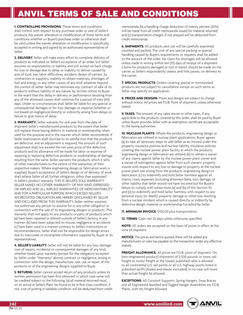
ANVIL TERMS OF SALE AND CONDITIONS
www.anvilintl.com242
1. CONTROLLING PROVISIONS: These terms and conditions shall control with respect to any purchase order or sale of Seller’s products. No waiver, alteration or modification of these terms and conditions whether on Buyer’s purchase order or otherwise shall be valid unless the waiver, alteration or modification is specifically accepted in writing and signed by an authorized representative of Seller.
2. DELIVERY: Seller will make every effort to complete delivery of products as indicated on Seller’s acceptance of an order, but Seller assumes no responsibility or liability, and will accept no back charge, for loss or damage due to delay or inability to deliver caused by acts of God, war, labor difficulties, accident, delays of carriers, by contractors or suppliers, inability to obtain materials, shortages of fuel and energy, or any other causes of any kind whatever beyond the control of Seller. Seller may terminate any contract of sale of its products without liability of any nature, by written notice to Buyer, in the event that the delay in delivery or performance resulting from any of the aforesaid causes shall continue for a period of sixty (60) days. Under no circumstances shall Seller be liable for any special or consequential damages or for loss, damage, or expense (whether or not based on negligence) directly or indirectly arising from delays or failure to give notice of delay.
3. WARRANTY: Seller warrants for one year from the date of shipment Seller’s manufactured products to the extent that Seller will replace those having defects in material or workmanship when used for the purpose and in the manner which Seller recommends. If Seller examination shall disclose to its satisfaction that the products are defective, and an adjustment is required, the amount of such adjustment shall not exceed the net sales price of the defective products and no allowance will be made for labor or expense of repairing or replacing defective products or workmanship of damage resulting from the same. Seller warrants the products which it sells of other manufacturers to the extent of the warranties of their respective makers. Where engineering design or fabrication work is supplied, Buyer’s acceptance of Seller’s design or of delivery of work shall relieve Seller of all further obligation, other than expressed in Seller’s product warranty. THIS IS SELLER’S SOLE WARRANTY. SELLER MAKES NO OTHER WARRANTY OF ANY KIND, EXPRESSED OR IMPLIED AND ALL IMPLIED WARRANTIES OF MERCHANTABILITY AND FOR A PARTICULAR PURPOSE WHICH EXCEED SELLER’S AFORESTATED OBLIGATION ARE HEREBY DISCLAIMED BY SELLER AND EXCLUDED FROM THIS WARRANTY. Seller neither assumes, nor authorizes any person to assume for it, any other obligation in connection with the sale of its engineering designs or products. This warranty shall not apply to any products or parts of products which (a) have been repaired or altered outside of Seller’s factory, in any manner; (b) have been subjected to misuse, negligence or accidents; (c) have been used in a manner contrary to Seller’s instructions or recommendations. Seller shall not be responsible for design errors due to inaccurate or incomplete information supplied by Buyer or its representatives.
4. SELLER’S LIABILITY: Seller will not be liable for any loss, damage, cost of repairs, incidental or consequential damages of any kind, whether based upon warranty (except for the obligation accepted by Seller under “Warranty” above), contract or negligence, arising in connection with the design, manufacture, sale, use or repair of the products or of the engineering designs supplied to Buyer.
5. RETURNS: Seller cannot accept return of any products unless its written permission has been first obtained, in which case same will be credited subject to the following: (a) all material returned must, on its arrival at Seller’s Plant, be found to be in first-class condition; if not, cost of putting in saleable condition will be deducted from credit
memoranda; (b) a handling charge deduction of twenty percent (20%) will be made from all credit memoranda issued for material returned; and (c) transportation charges, if not prepaid will be deducted from credit memoranda.
6. SHIPMENTS: All products sent out will be carefully examined, counted and packed. The cost of any special packing or special handling caused by Buyer’s requirements or requests shall be added to the amount of the order. No claim for shortages will be allowed unless made in writing within ten (10) days of receipt of a shipment. Claims for products damaged or lost in transit should be made on the carrier, as Seller’s responsibility ceases, and title passes, on delivery to the carrier.
7. SPECIAL PRODUCTS: Orders covering special or nonstandard products are not subject to cancellation except on such terms as Seller may specify on application.
8. PRICES AND DESIGNS: Prices and designs are subject to change without notice. All prices are F.O.B. Point of shipment, unless otherwise stated.
9. TAXES: The amount of any sales, excise or other taxes, if any, applicable to the products covered by this order, shall be paid by Buyer unless Buyer provides Seller with an exemption certificate acceptable to the taxing authorities.
10. NUCLEAR PLANTS: Where the products, engineering design or fabrication are utilized in nuclear plant applications, Buyer agrees: (a) to take all necessary steps to add Seller as an insured under the property insurance policies and nuclear liability insurance policies covering the nuclear power plant facility at which the products, engineering design or fabrication are utilized; (b) to obtain a waiver of any claims against Seller by the nuclear power plant owner and a waiver of subrogation against Seller from such owners’ property insurer with respect to any loss or damage to property at the nuclear power plant site arising from the products, engineering design or fabrication; (c) to indemnify and hold Seller harmless against all claims, costs, expenses (including attorneys fees), loss, damage, or other liability that Seller would not have incurred but for Buyer’s failure to comply with subsections (a) and (b) of this Section 10; and (d) to indemnify and hold Seller harmless with respect to any personal injury (or death), property damage or other loss resulting from a nuclear incident which is caused directly or indirectly by defective design, material or workmanship furnished by Seller.
11. MINIMUM INVOICE: $100.00 plus transportation.
12. TERMS: Cash, net 30 days unless otherwise specified.
NOTE: All orders are accepted on the basis of prices in effect at the time of shipment.
NOTICE: The prices and terms quoted, there will be added any manufacturers or sales tax payable on the transaction under any effective statute.
FREIGHT ALLOWANCE: All prices are F.O.B. point of shipment. On (non-engineered product) shipments of 2,500 pounds or more, rail freight or motor freight at the lowest published rates is allowed to all continental U.S. rail points or all U.S. highway points listed in published tariffs (Alaska and Hawaii excluded). In no case will more than actual freight be allowed.
EXCEPTIONS: All Constant Supports, Spring Hangers, Sway Braces and all Engineered, Bundled and Tagged Hanger Assemblies are F.O.B. Plants, with No Freight Allowed.
PH-11.11
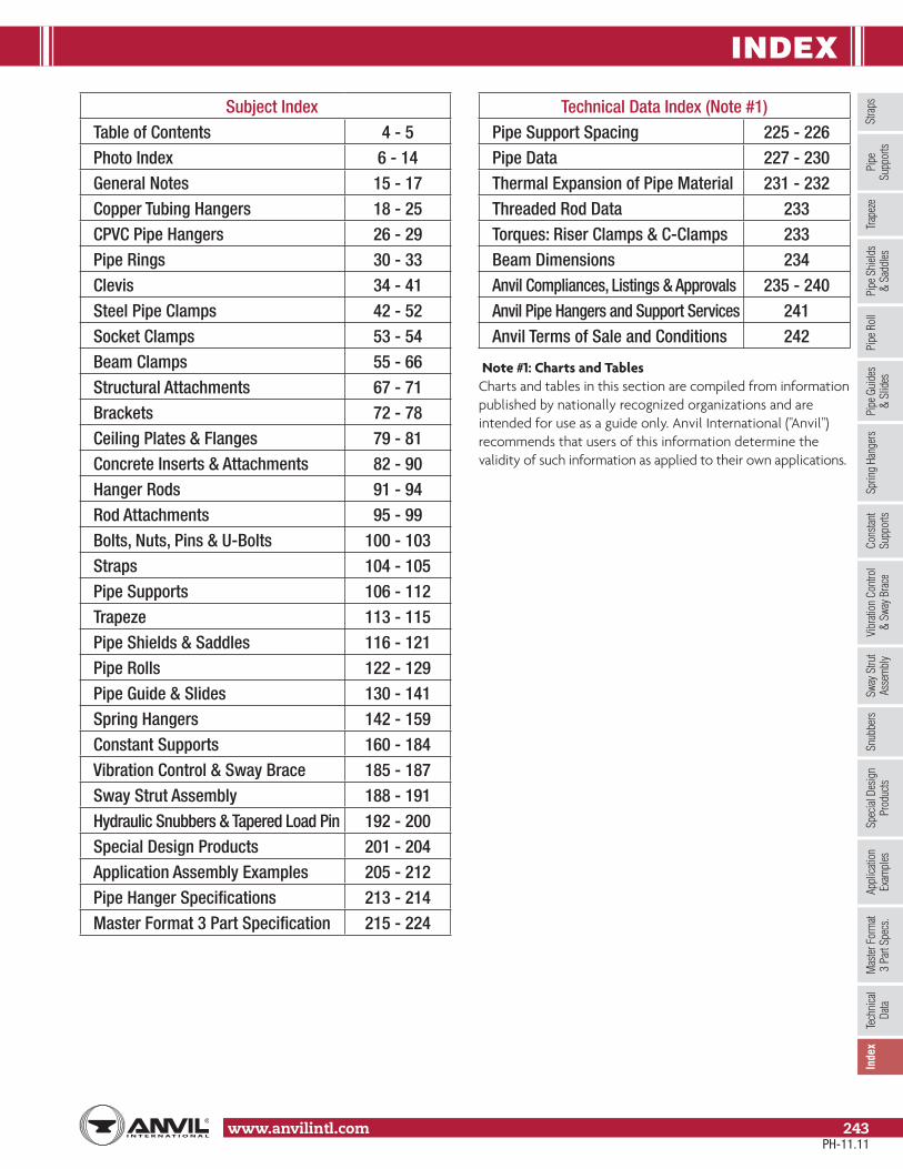
INDEX
Stra
psSp
ring
Hang
ers
Cons
tant
Supp
orts
Vibr
ation
Con
trol
& Sw
ay B
race
Sway
Stru
tAs
sem
bly
Snub
bers
Appl
icatio
nEx
ampl
esSp
ecial
Des
ign
Prod
ucts
Trap
eze
Pipe
Rol
lPi
pe G
uide
s&
Slid
esPi
pe S
hield
s&
Sadd
lesPi
peSu
ppor
tsIn
dex
www.anvilintl.com 243
Tech
nica
lDa
taM
aster
For
mat
3 Pa
rt Sp
ecs.
Subject IndexTable of Contents 4 - 5Photo Index 6 - 14General Notes 15 - 17Copper Tubing Hangers 18 - 25CPVC Pipe Hangers 26 - 29Pipe Rings 30 - 33Clevis 34 - 41Steel Pipe Clamps 42 - 52Socket Clamps 53 - 54Beam Clamps 55 - 66Structural Attachments 67 - 71Brackets 72 - 78Ceiling Plates & Flanges 79 - 81Concrete Inserts & Attachments 82 - 90Hanger Rods 91 - 94Rod Attachments 95 - 99Bolts, Nuts, Pins & U-Bolts 100 - 103Straps 104 - 105Pipe Supports 106 - 112Trapeze 113 - 115Pipe Shields & Saddles 116 - 121Pipe Rolls 122 - 129Pipe Guide & Slides 130 - 141Spring Hangers 142 - 159Constant Supports 160 - 184Vibration Control & Sway Brace 185 - 187Sway Strut Assembly 188 - 191Hydraulic Snubbers & Tapered Load Pin 192 - 200Special Design Products 201 - 204Application Assembly Examples 205 - 212Pipe Hanger Specifications 213 - 214Master Format 3 Part Specification 215 - 224
Technical Data Index (Note #1)Pipe Support Spacing 225 - 226Pipe Data 227 - 230Thermal Expansion of Pipe Material 231 - 232Threaded Rod Data 233Torques: Riser Clamps & C-Clamps 233Beam Dimensions 234Anvil Compliances, Listings & Approvals 235 - 240Anvil Pipe Hangers and Support Services 241Anvil Terms of Sale and Conditions 242
Note #1: Charts and TablesCharts and tables in this section are compiled from information published by nationally recognized organizations and are intended for use as a guide only. Anvil International ("Anvil") recommends that users of this information determine the validity of such information as applied to their own applications.
PH-11.11

INDEX
www.anvilintl.com244
Fig. 14 through Fig. 211 Figure Number Provided From PageFig. 14 ▲ 62Fig. 38SD ■▲ 201Fig. 40 ■▲ 43Fig. 40SD ■▲ 203Fig. 41SD ■▲ 203Fig. 42SD ■▲ 204Fig. 45 ■▲ 114Fig. 46 ■▲ 113Fig. 47 ▲* 88Fig. 49 ▲* 89Fig. 50 ■▲ 115Fig. 52 ▲* 90Fig. 53SD ■▲ 201Fig. 54 ■ 68Fig. 55 & Fig. 55L ▲* 67Fig. 60 ▲* 70Fig. 62 Type A, B & C ■▲ 106Fig. 63 Type A, B, C, P & T ■▲ 107Fig. 65 N/A 35Fig. 66 ▲ 69Fig. 67 ▲ 34Fig. 67F ▲ 22Fig. 69 ▲ 33Fig. 69F ▲ 21Fig. 71SD ■ 201Fig. 72SD ■ 202Fig. 75SD ■▲ 202Fig. 76SD ■▲ 202Fig. 80-V Type A ■ 168Fig. 80-V Type B ■ 169Fig. 80-V Type C ■ 170Fig. 80-V Type D ■ 171Fig. 80-V Type E ■ 172Fig. 80-V Type G ■ 173Fig. 80-V Type A, B & C ■ 174Fig. 81-H Type A ■ 175Fig. 81-H Type B ■ 176Fig. 81-H Type C ■ 177Fig. 81-H Type D ■ 178Fig. 81-H Type E ■ 179Fig. 81-H Type F Upthrust ■ 180Fig. 81-H Type A, B, C & E ■ 181Fig. 82 ■ 142 - 143, 152 - 153Fig. 86 & Fig. 88 ● 55Fig. 89 ▲ 57Fig. 89X ▲ 57Fig. 92 ● 58Fig. 93 ● 59Fig. 94 ● 60Fig. 95 ▲ 56Fig. 98, Fig. C-98 Series ■ 142 - 143, 154 - 155
Figure Number Provided From PageFig. 100 ▲ 44Fig. 103 ▲ 44Fig. 104 ● 32Fig. 108 ● 30Fig. 110R ● 96Fig. 112 ● 71Fig. 113 ● 71Fig. 114 ● 96Fig. 120 ▲ 103Fig. 126 ● 104Fig. 127 ▲ 79Fig. 128R ● 80Fig. 133 ▲ 63Fig. 134 ▲ 63Fig. 135, Fig. 135E & Fig. 135R ▲ 95Fig. 136 & Fig. 136R ● 95Fig. 137, Fig. 137S & Fig. 137C ▲ 102 - 103Fig. 138R N/A 31Fig. 140 ■▲ 92Fig. 142 ▲ 91Fig. 146 ✝ 91Fig. 148 ■ 94Fig. 152 ● 82Fig. 153 ● 81Fig. 157 ● 97Fig. 160 thru Fig. 166A ■▲ 118 - 121Fig. 167 ▲ 116Fig. 168 ▲ 117Fig. 170 ■ 184Fig. 171 ▲ 123Fig. 175 ▲ 126Fig. 177 ▲ 122Fig. 178 ▲ 124Fig. 181 ▲ 125Fig. 185 ▲ 26Fig. 186 ▲ 27Fig. 187 ▲ 28Fig. 188 ▲ 29Fig. 189 ▲ 74Fig. 190 ▲ 75Fig. 191 ▲ 108Fig. 192 ▲ 108Fig. 194 ▲ 76Fig. 195 ▲ 77Fig. 199 ▲ 78Fig. 200, C-200 ■ 196 - 199Fig. 201, C-201 ■ 196 - 199Fig. 202 ● 72Fig. 206 ▲ 73Fig. 207 ▲ 73Fig. 211, C-211 ■ 188 - 189
● = Columbia, PA ■ = North Kingstown, RI ▲ = Henderson, TN✝ = Regional Service Centers * = rod dia. over 11⁄2" (North Kingstown, RI)
For contact information for the locations listed above, please refer to the back cover.
PH-11.11

INDEX
Stra
psSp
ring
Hang
ers
Cons
tant
Supp
orts
Vibr
ation
Con
trol
& Sw
ay B
race
Sway
Stru
tAs
sem
bly
Snub
bers
Appl
icatio
nEx
ampl
esSp
ecial
Des
ign
Prod
ucts
Trap
eze
Pipe
Rol
lPi
pe G
uide
s&
Slid
esPi
pe S
hield
s&
Sadd
lesPi
peSu
ppor
tsIn
dex
www.anvilintl.com 245
Tech
nica
lDa
taM
aster
For
mat
3 Pa
rt Sp
ecs.
Figure Number Provided From PageFig. 212 ▲ 45, 141Fig. 212FP ▲ 46Fig. 216 ▲ 47Fig. 217 ▲ 62Fig. 218 ● 64Fig. 222, C-222 ■ 190 - 191Fig. 224 ■ 51Fig. 227 ▲ 61Fig. 228 ▲ 65Fig. 230 ▲* 99Fig. 233 ■ 99Fig. 243 ■▲ 105Fig. 244 ■▲ 105Fig. 246 ■ 52Fig. 248 & Fig. 248L ▲ 92Fig. 248X ▲ 93Fig. 253 ▲* 92Fig. 255 ▲ 130 - 131Fig. 256 ▲ 132 - 133Fig. 257 ▲ 134 - 137Fig. 257A ▲ 134 - 137Fig. 258 ▲ 109Fig. 259 ▲ 112Fig. 260 ▲ 36Fig. 260 ISS ▲ 37 - 39Fig. 261 ▲ 42Fig. 262 ▲ 104Fig. 264 ▲ 110Fig. 265 ▲ 111Fig. B-268, C-268 Type A ■ 147Fig. B-268, C-268 Type B & C ■ 148Fig. B-268, C-268 Type D & E ■ 149Fig. B-268, C-268 Type F ■ 150Fig. B-268, C-268 Type G ■ 151Fig. 271 ▲ 128Fig. 274 & Fig. 274P ▲ 129Fig. 275 ▲ 129Fig. 277 ▲ 127Fig. 278 & Fig. 278L ▲* 93Fig. 278X ▲* 93Fig. 281 ▲ 84Fig. 282 ● 83Fig. 284 ▲ 87Fig. 285 ▲ 85Fig. 286 ✝ 86Fig. 290 & Fig. 290L ▲* 97Fig. 291 ■▲ 100Fig. 292 & Fig. 292 L ▲ 66Fig. 295 ▲ 48Fig. 295A ▲ 49Fig. 295H ■▲ 50
Fig. 212 through Fig. CT-255 Figure Number Provided From PageFig. 296, 301, C-296, C-301 ■ 185 - 186Fig. 297, 298, 302, 303 ■ 187Fig. 299 ▲* 98Fig. 300 ▲ 40Fig. 312 ■ 200Fig. 395 ● 79Fig. 432 ▲ 140Fig. 436 & Fig. 436A ▲ 134 - 137Fig. 439 & Fig. 439A ▲ 138 - 139Fig. 590 ▲ 41Fig. 595 & Fig. 594 ▲ 53Fig. 600 & Fig. 599 ▲ 54Fig. 640, C-640 ■ 188 - 189Fig. 3306, 3307 ■ 192 - 195Fig. CT-65 N/A 19Fig. CT-69 ▲ 18Fig. CT-121 ▲ 23Fig. CT-128R ● 20Fig. CT-138R N/A 20Fig. CT-255 ▲ 24 - 25
Anvil Compliances, Listings and Approvals 235 - 240Anvil Pipe Hangers and Support Services 241Anvil Terms of Sale and Conditions 242Beam Dimensions 234Constant Support, Check List 183Constant Support, Total Travel & Selection Chart 164 - 167Copper Tube Data 228CPVC Pipe Support Spacing 225Hexagon Nuts & Machine Bolts 101
Manufacturers Standardization Society -Hanger Type Index 240
Master Format 3 Part Specification 215 - 224Maximum Recommended Applied Torques 233
Model R 80-V, 81-H Mathematically Perfect Pipe Support 160 - 163
Quadruple Spring, Quadruple Spring-CR Series 158 - 159Spring Hanger Check List 146Spring Hanger Size & Series Selection 144 - 145Standard Galvanizing Practice 16 -17Standard Materials 15Steel Pipe Data 227 - 228Thermal Expansion of Pipe Material 231 - 232Triple Spring, Triple Spring-CR Series 156 - 157Typical Pipe Hanger Specification 213 - 214Weight Chart - Fig. 80-V & Fig.81-H 182
● = Columbia, PA ■ = North Kingstown, RI ▲ = Henderson, TN✝ = Regional Service Centers * = rod dia. over 11⁄2" (North Kingstown, RI)
For contact information for the locations listed above, please refer to the back cover.
PH-11.11

NOTES
www.anvilintl.com246

NOTES
www.anvilintl.com 247

NOTES
www.anvilintl.com248

PIPE HANGERS & SUPPORT CATALOG
ORDER DOCUMENT #165
GRUVLOK MECHANICAL
PIPING PRODUCTS CATALOG
ORDER DOCUMENT #040
PIPE FITTINGS CATALOG ORDER DOCUMENT #010
ANVIL-STRUT METAL FRAMING
PRODUCT & ENGINEERING CATALOG
ORDER DOCUMENT #125
PIPE FITTERS HANDBOOK
ORDER DOCUMENT #030

B U I L D I N G C O N N E C T I O N S T H A T L A S T
We built our reputation from the ground up.
Anvil’s history stretches back to the mid 1800s,when a company named Grinnell® began providingits customers with the finest quality pipe products.Since 2000, those quality products and services—and the people who provide them—have beenknown as Anvil® International. Anvil® customers receive the quality and integrity that have been building strong connections in both productsand business relationships for over 150 years.
TRUSTEDFOR 150 YEARS
Focused Product Line:
Anvil® Malleable and CastIron Fittings
Anvil® Hangers, Supportsand Struts
Beck Welded Pipe Nipples
Anvil® Seamless PipeNipples
Anvil® Steel Pipe Couplingsand Small Steel Fittings
Merit® Tee-Lets and DropNipples
Gruvlok® Couplings,Fittings and Valves
SPFTM Malleable and Castand Ductile Iron Fittings
SPF TM Grooved Fittings and O’Lets
J.B. Smith Swage Nipplesand Bull Plugs
Catawissa® Wing Unionsand Check Valves
Today Anvil® International is the largest and most complete fitting and hanger manufacturer in the world.
2004 Anvil® International acquires Star Pipe Products, Building and Construction Divisions (SPF) and forms AnvilStarTM Fire Products Division.
2001 Anvil® International acquires Merit® Manufacturingand Beck Manufacturing.
2000 The industry’s trusted manufacturer of pipefittings, hangers and grooved fittingsis renamed Anvil® International, Inc.
1999 Tyco sells the distribution and manufacturingoperations known up to this point as ”Grinnell Supply Sales”, but keeps the Grinnell® trademark.
1994 J.B. Smith™ and Catawissa™ join the Grinnell Supply Sales and Manufacturing division.
1850 Providence Steam & Gas Pipe Co. is formed, andFrederick Grinnell purchases a controlling interest.
1909 Frederick Grinnell opens a foundry in Cranston, RI.Companies express interest in buying its pipingproducts, laying the groundwork for what wouldbecome the Grinnell Supply Sales Division. It would be these manufacturing and sales operations thateventually become Anvil® International.
1919 General Fire Extinguisher Co. becomes Grinnell Co.
1960 Gruvlok® line of grooved fittings is introduced.
1969 Grinnell Co. acquired by International Telephone and Telegraph. Two years later, ITT divests the FireProtection Division, but keeps the manufacturingand sales divisions that will become known asAnvil® International.
Grinnell® is a registered trademark of Grinnell Corporation, a Tyco International Ltd. company.
ANVIL BRANDS:

B R A N D S O F A N V I L I N T E R N AT I O N A L
Anvil® product lines include malleable and cast iron fittings, unions and flanges; seamless steel pipe nipples; steel pipe couplings; universal anvilets; forged steel fittings and unions; pipe hangers and supports; threaded rod; and engineered hangers.
The Gruvlok® product line consists of couplings for grooved and plain-end fittings, butterfly valves and check valves; flanges; pump protection components; pipe grooving tools; as well as copper and stainless steel system components.
Anvil-Strut™ products include a complete line of channel in stock lengths of 10 and 20 feet, with custom lengths available upon request. A variety of fittings and accessories are also offered. All products can be ordered in an assortment of finishes and material choices including SupR-Green™, Zinc Trivalent Chromium, pre-galvanized, hot-dipped galvanized, electro-galvanized, aluminum, plain, and stainless steel.
JB Smith™ is the leading manufacturer of oil country tubular fittings, swages and bull plugs – all meeting API specifications. Offering tubing nipples, casing nipples as well as a full line of traditional line pipe and oil country threads in every schedule, JB Smith is the resource for all your oilfield needs.
Catawissa™ NACE and API approved wing unions for Standard Service are offered in non-pressure seal ends as well as threaded and butt weld, and are interchangeable with most leading union manufacturers. Fully traceable and available with complete mill certifications, Catawissa’s oilfield wing union product line includes the standard ball-and-cone design plus our unique Figure 300 Flat Face design, where space and pipe line separation are a consideration.
The SPF/Anvil™ product line includes a variety of internationally sourced products such as grooved couplings, fittings and flanges, cast iron, malleable iron and ductile iron threaded fittings, steel pipe nipples, as well as o’lets.
The Merit® product line includes a variety of tee-lets, drop nipples, and steel welding flanges for fire protection applications. Most Merit products are UL/ULC Listed, FM Approved, and rated from 175 to 300 psi.
Steel pipe nipples and steel pipe couplings are manufactured in accordance with the ASTM A733 Standard Specification for Welded and Seamless Carbon Steel and Stainless Steel Pipe Nipples. Steel pipe couplings are manufactured in accordance with the ASTM A865 Standard Specification for Threaded Couplings, Steel, Black or Zinc-Coated (Galvanized) Welded or Seamless, for Use in Steel Pipe Joints. API couplings are manufactured in accordance with the API Specification for line pipe.
Canvil® manufactures low pressure hexagon reducer bushings, as well as plugs and hex caps up to 1” in diameter in various finishes including Oil Treat, Phosphate and Electro Galvanized. In addition, Canvil manufactures A105 hex or round material in class 3000 and 6000 pound, forged steel couplings and bar stock products offered as either as normalized (A105N) or non-normalized (A105) that are fully traceable for mechanicals and chemistry through our MTR program.
Anvil EPS-Engineered Pipe Supports are products used to support piping systems under thermal, seismic, and other dynamic loading conditions. The product line encompasses variable spring hangers, constant supports, sway struts and snubbers as well as standard and special design clamps. Anvil EPS brings the highest quality products and innovative engineering solutions to common and uncommon piping system problems.

U.S. REGIONAL SERVICE CENTERS
Anvil International CanadaCustomer Service Center390 Second AvenueP.O. Box 40Simcoe, Ontario N3Y 4K9
Tel: 519-426-4551Fax: 519-426-5509
CANADA SERVICE CENTER
www.anvilintl.com
Northern RegionRegional Distribution & Customer Service Center
750 Central Avenue University Park, IL 60484
Tel: 708-885-3000 Fax: 708-534-5441 Toll Free: 1-800-301-2701
Southern RegionRegional Distribution & Customer Service Center1401 Valley View Lane, Suite 150Irving, TX 75061
Tel: 972-871-1206 Fax: 972-641-8946 Toll Free: 1-800-451-4414
INTERNATIONAL SALES
Anvil EPSEngineered Pipe SupportsCustomer Service Center
160 Frenchtown RoadNorth Kingstown, RI 02852
Tel: 401-886-3000 Fax: 401-886-3010Toll Free: 1-877-406-3108
Corporate Offices110 Corporate Drive, Suite 10 P.O. Box 3180 Portsmouth, NH 03801-3180
Tel: 603-422-8000 Fax: 603-422-8033
E-mail: [email protected]
#165/Printed in USA/© Copyright 2011Revision Date: 11.16.11
B U I L D I N G C O N N E C T I O N S T H A T L A S T
Mexico, Puerto Rico andLatin AmericaInternational Customer Service
Tel: +1-708-885-3000 Fax: +1-708-534-5441
Europe and Middle East RegionRick van [email protected]
Tel: +31-53-5725570 Fax: +31-53-5725579


