
PIAGGIO WOULD LIKE TO THANK YOU
for choosing one of its products. We have prepared this booklet to help you to get the very best from your scooter. Please read it carefully before ridingthe scooter for the first time. It contains information, tips and precautions for using your scooter. It also describes features, details and devices to assureyou that you have made the right choice. We believe that if you follow our suggestions, you will soon get to know your new vehicle and it will serve youwell for a long time to come. This booklet forms an integral part of the scooter; should the scooter be sold, it must be transferred to the new owner.
BEVERLY Cruiser 250ie

The instructions given in this manual are intended to provide a clear, simple guide to using your scooter; this booklet also details routine maintenanceprocedures and regular checks that should be carried out on the vehicle at an authorised Dealer or Service Centre. The booklet also containsinstructions for simple repairs. Any operations not specifically described in this manual require the use of special tools and/or particular technicalknowledge: to carry out these operations refer to any authorised Dealer of Service Centres.
2

Personal safety
Failure to completely observe these instructions will result in serious risk of personalinjury.
Safeguarding the environment
Sections marked with this symbol indicate the correct use of the vehicle to prevent dam-aging the environment.
Vehicle intactness
The incomplete or non-observance of these regulations leads to the risk of seriousdamage to the vehicle and sometimes even the invalidity of the guarantee.
The signs that you see on this page are very important. They are used to highlight thoseparts of the booklet that should be read with particular care. As you can see, each signconsists of a different graphic symbol, making it quick and easy to locate the varioustopics.
3

4

INDEX
VEHICLE...................................................................................... 7Dashboard................................................................................ 9Analogue instrument panel....................................................... 11Key switch................................................................................. 11
Locking the steering wheel.................................................... 12Releasing the steering wheel................................................ 12
Switch direction indicators........................................................ 13Horn button............................................................................... 13Light switch............................................................................... 14Start-up button.......................................................................... 14Engine stop button.................................................................... 15The immobilizer system............................................................ 15
Keys...................................................................................... 16Immobilizerdevice enabled indicator led............................... 17Operation............................................................................... 17Programming the immobilizer system................................... 18
Accessing the fuel tank............................................................. 20Power supply socket................................................................. 20The saddle................................................................................ 21
Opening the saddle............................................................... 23Identification.............................................................................. 23Rear top box opening................................................................ 24Bag clip..................................................................................... 25
USE.............................................................................................. 27Checks...................................................................................... 28Refuelling.................................................................................. 28Tyre pressure............................................................................ 30Shock absorbers adjustment.................................................... 31Running in................................................................................. 32Starting up the engine............................................................... 32
Precautions........................................................................... 33Difficult start up......................................................................... 34Stopping the engine.................................................................. 34
Stand......................................................................................... 35Automatic transmission............................................................. 36Safe driving............................................................................... 37
MAINTENANCE........................................................................... 39Engine oil level.......................................................................... 40
Engine oil level check............................................................ 40Engine oil top-up................................................................... 41Warning light (insufficient oil pressure)................................. 41Engine oil change.................................................................. 41
Hub oil level.............................................................................. 43Tyres......................................................................................... 45Spark plug dismantlement........................................................ 46Removing the air filter............................................................... 47Air filter cleaning....................................................................... 48Cooling fluid level...................................................................... 49Checking the brake oil level...................................................... 50
Braking system fluid top up................................................... 51Battery....................................................................................... 52
Use of a new battery............................................................. 53Long periods of inactivity.......................................................... 54Fuses........................................................................................ 54Front light group........................................................................ 59
Headlight adjustment............................................................. 60Front direction indicators........................................................... 61Rear optical unit........................................................................ 62Number plate light..................................................................... 64Helmet compartment lighting bulb............................................ 65Rear-view mirrors...................................................................... 65Front and rear disc brake.......................................................... 66Puncture.................................................................................... 67Periods of inactivity................................................................... 68Cleaning the vehicle.................................................................. 68
TECHNICAL DATA...................................................................... 73
5

Kit equipment............................................................................ 78SPARE PARTS AND ACCESSORIES........................................ 79
Warnings................................................................................... 80PROGRAMMED MAINTENANCE............................................... 83
Scheduled maintenance table................................................... 84
6

BEVERLYCruiser 250ie
Chap. 01Vehicle
7

01_01
8
1 Ve
hicl
e
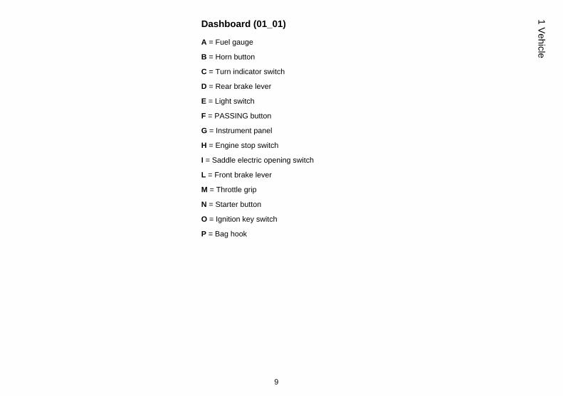
Dashboard (01_01)
A = Fuel gauge
B = Horn button
C = Turn indicator switch
D = Rear brake lever
E = Light switch
F = PASSING button
G = Instrument panel
H = Engine stop switch
I = Saddle electric opening switch
L = Front brake lever
M = Throttle grip
N = Starter button
O = Ignition key switch
P = Bag hook
9
1 Vehicle
01_02
10
1 Ve
hicl
e
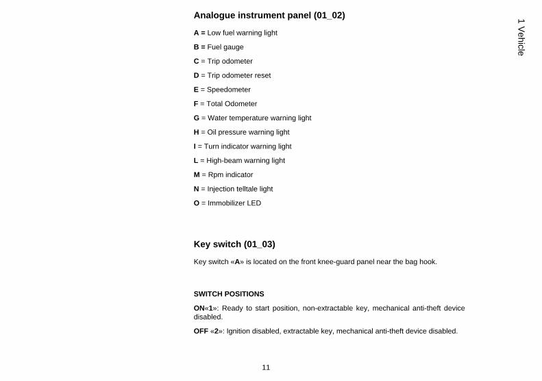
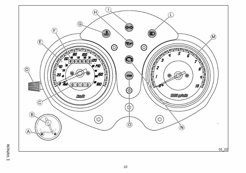
Analogue instrument panel (01_02)
A = Low fuel warning light
B = Fuel gauge
C = Trip odometer
D = Trip odometer reset
E = Speedometer
F = Total Odometer
G = Water temperature warning light
H = Oil pressure warning light
I = Turn indicator warning light
L = High-beam warning light
M = Rpm indicator
N = Injection telltale light
O = Immobilizer LED
Key switch (01_03)
Key switch «A» is located on the front knee-guard panel near the bag hook.
SWITCH POSITIONS
ON«1»: Ready to start position, non-extractable key, mechanical anti-theft devicedisabled.
OFF «2»: Ignition disabled, extractable key, mechanical anti-theft device disabled.
11
1 Vehicle
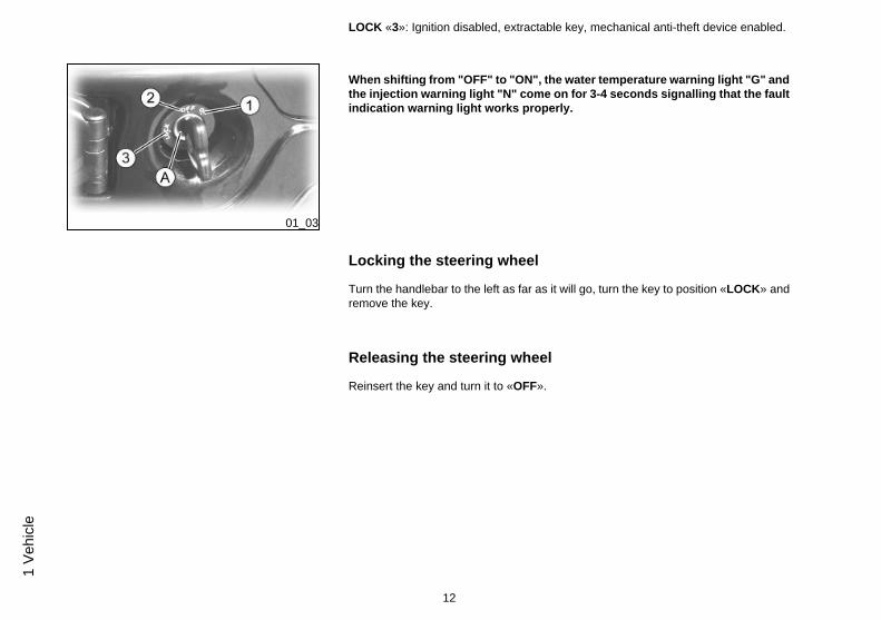
LOCK «3»: Ignition disabled, extractable key, mechanical anti-theft device enabled.
01_03
When shifting from "OFF" to "ON", the water temperature warning light "G" andthe injection warning light "N" come on for 3-4 seconds signalling that the faultindication warning light works properly.
Locking the steering wheel
Turn the handlebar to the left as far as it will go, turn the key to position «LOCK» andremove the key.
Releasing the steering wheel
Reinsert the key and turn it to «OFF».
12
1 Ve
hicl
e

01_04
Switch direction indicators (01_04)
Move the switch «C» to the left to indicate a left turn; Move the switch «C» to the rightto indicate a right turn; Press the central part of the switch «C» to deactivate the turnindicators.
01_05
Horn button (01_05)
Push the button «B» to sound the horn.
13
1 Vehicle

01_06
Light switch (01_06)
When the light switch «E» is set to «1», the low-beam light is on. When set to «2», thehigh-beam light is activated. Push the button «F» and the high-beam light is flashed.
01_07
Start-up button (01_07)
To start the engine, pull either brake lever and press the button «N».
14
1 Ve
hicl
e
01_08
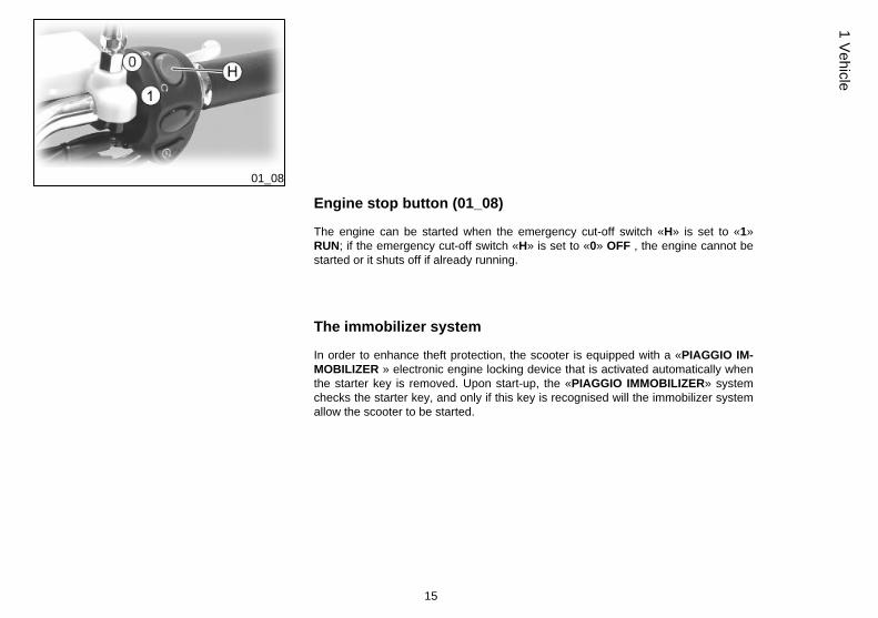
Engine stop button (01_08)
The engine can be started when the emergency cut-off switch «H» is set to «1»RUN; if the emergency cut-off switch «H» is set to «0» OFF , the engine cannot bestarted or it shuts off if already running.
The immobilizer system
In order to enhance theft protection, the scooter is equipped with a «PIAGGIO IM-MOBILIZER » electronic engine locking device that is activated automatically whenthe starter key is removed. Upon start-up, the «PIAGGIO IMMOBILIZER» systemchecks the starter key, and only if this key is recognised will the immobilizer systemallow the scooter to be started.
15
1 Vehicle

01_09
01_10
01_11
Keys (01_09, 01_10, 01_11)
Two types of keys come with the vehicle. The red-handgrip key "A" is the "MAS-TER" key. Only a single copy of this key is supplied, which is necessary to programall your other keys and for your dealer to perform some maintenance operations. Forthis reason it is advised that it be used only in exceptional circumstances. The blackkey "B" (single copy supplied) is used for normal operations such as:
- engine start up
- glove-box opening
Together with the keys comes a CODE CARD which is imprinted with the mechanicalcode of the keys.
WARNING
LOSING THE RED KEY PREVENTS ANY REPAIRS OF THE 'PIAGGIO IMMOBIL-IZER' SYSTEM AND THE ENGINE CONTROL UNIT.
WARNING
KEEP THE 'CODE CARD' AND THE RED HANDGRIP KEY IN A SAFE PLACE (NOTON YOUR VEHICLE).
16
1 Ve
hicl
e

01_12
Immobilizerdevice enabled indicator led (01_12)
Activation of the «PIAGGIO IMMOBILIZER» system is signalled by a flashing «O»warning light.
In order to reduce battery discharge, the indicator LED turns off automatically after 48hours of uninterrupted functioning.
Should the system fail, different LED flashing patterns will provide the AuthorisedService Centre with information on the type of fault detected.
Operation
Every time the starter key is extracted from either the «OFF» or «LOCK» position, theprotection system activates the engine lock. Turning the key to «ON», with the emer-gency cut-off switch set to «ON» and the side stand up, disables the engine lockprovided that the safety system recognises the code transmitted by the key. If the codeis not recognised, turn the key first to "OFF" and then to "ON"; if the lock cannot bedisabled, try with the other key supplied (red-coloured). If the engine cannot be started,contact an Authorised Service Centre, which is provided with the electronic equip-ment required to detect and repair the system. The immobilizer is also activated whenthe emergency cut-off switch stops the engine or the side stand is lowered. This hap-pens even if the starter key is in «ON». When additional keys are required, pleasenote that data storage (up to 7 keys max.) must be done on all keys, both new andexisting ones. Take the red-handgrip key and all the black keys supplied to an Au-
17
1 Vehicle

thorised Service Centre. The codes of keys not submitted for the new storageprocedure are deleted from the memory. Any lost keys will therefore not be enabledto start the engine.
WARNING
EACH KEY HAS ITS OWN AND UNIQUE CODE, WHICH MUST BE STORED BYTHE SYSTEM CONTROL UNIT.
VIOLENT SHOCKS MAY AFFECT THE ELECTRONIC COMPONENTS OF THEKEY.
IF OWNERSHIP OF THE VEHICLE IS TRANSFERRED, THE RED-HANDGRIP KEY(AS WELL AS THE OTHER KEYS) AND THE "CODE CARD" MUST ALSO BETRANSFERRED TO THE NEW OWNER.
Programming the immobilizer system
The procedure for programming the «PIAGGIO IMMOBILIZER» system and/or forstoring other key codes is described below.
The programming procedure should be carried out with the engine stop switch set to«RUN».
Procedure start - red key
Insert the red-handgrip key in the switch key (in "OFF" position) and turn it to "ON".After 1 - 3 seconds, turn the key to "OFF" again and pull it out.
18
1 Ve
hicl
e
Intermediate step - black key
After pulling out the red key, insert the black key within 10 seconds and promptly turnit to "ON". After 1-3 seconds, turn the key to "OFF" again and pull it out. In this way,a maximum of 7 black keys can be programmed by repeating the above procedurekeeping the indicated times.
Final step - red key
After pulling out the last black key, insert the red key again and turn it to "ON" (thisoperation should be performed within 10 seconds of pulling out the previous key).Leave it in this position for 1 to 3 seconds and return it to the «OFF» position.
Proper programming check
Insert the red key disabling the transponder (i.e., tilt the key cap by 90°) and turn thekey to "ON". Perform the engine start-up operation. Ensure that the engine does notstart. Insert the black key and repeat the start-up operation. Check that engine starts.
WARNING
SHOULD THE ENGINE START WITH THE RED KEY (WITH TRANSPONDER OFF),OR IN THE EVENT OF WRONG OPERATION DURING PROGRAMMING, REPEATTHE PROCEDURE FROM THE BEGINNING.
19
1 Vehicle

01_13
01_14
Accessing the fuel tank (01_13, 01_14)
Insert the key into the switch and press down until the glove box opens. In the eventthat the key switch is in «LOCK», turn the key to «OFF» or «ON» before pressingdown. Press lever «B» and open the cover over the fuel tank cap «C».
01_15
Power supply socket (01_15)
There is a plug socket "D" inside the helmet compartment.
The plug socket may be used for external consumers (mobile phone, inspection light,etc.).
20
1 Ve
hicl
e
CAUTION
PROLONGED USE OF THE PLUG SOCKET MAY RESULT IN PARTIAL DIS-CHARGE OF THE BATTERY
Electric characteristicPlug socket
12 V - 180 W MAX
01_16
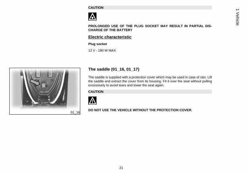
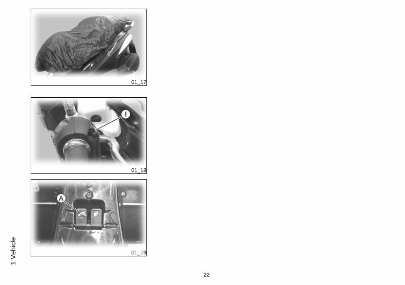
The saddle (01_16, 01_17)
The saddle is supplied with a protection cover which may be used in case of rain. Liftthe saddle and extract the cover from its housing. Fit it over the seat without pullingexcessively to avoid tears and lower the seat again.
CAUTION
DO NOT USE THE VEHICLE WITHOUT THE PROTECTION COVER.
21
1 Vehicle
01_17
01_18
01_19
22
1 Ve
hicl
e
Opening the saddle (01_19)
With the key set to «OFF» or «ON», or with engine on, the saddle can be opened bymeans of an electrical device by pressing button «I». If the electric opening does notwork, use the emergency lever "A". When the key is set to «LOCK» the saddle cannotbe opened.
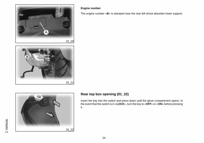
Identification (01_20, 01_21)
Identification registration numbers are made up of a prefix and a number stamped onthe chassis and on the engine. These numbers must always be quoted when orderingspare parts. We recommend checking that the chassis registration number stampedon the vehicle corresponds with that on the vehicle documentation.
CAUTION
BE REMINDED THAT ALTERING IDENTIFICATION REGISTRATION NUMBERSCAN LEAD TO SERIOUS PENAL SANCTIONS (IMPOUNDING OF THE VEHICLE,ETC.).
Chassis number
To read the chassis number, remove the lid «A» in the helmet compartment.
23
1 Vehicle
01_20
01_21
Engine number
The engine number «B» is stamped near the rear left shock absorber lower support.
01_22
Rear top box opening (01_22)
Insert the key into the switch and press down until the glove compartment opens. Inthe event that the switch is in «LOCK», turn the key to «OFF» or «ON» before pressingit.
24
1 Ve
hicl
e

01_23
Bag clip (01_23)
To use the retractile bag hook «B» mounted on the knee-guard panel, pull it slightlytowards the back part of the vehicle.
25
1 Vehicle

26
1 Ve
hicl
e

BEVERLYCruiser 250ie
Chap. 02Use
27
Checks
Before using the vehicle, check:
1. There is enough fuel in the fuel tank.
2. Front and rear brake fluid level
3. That tyres are properly inflated.
4. The correct functioning of the tail lights, the headlight, and the turn indicators.
5. The correct functioning of front and rear brakes.
6. The oil level in the gearcase.
7. The engine oil level.
8. The coolant level
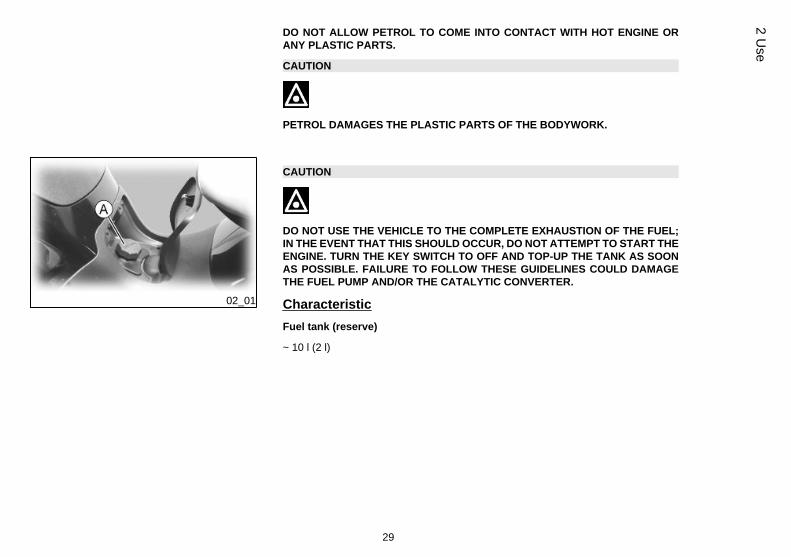
Refuelling (02_01)
Reach the fuel tank and unscrew the cap «A».
Use premium unleaded petrol, with minimum octane rating of 95.
A specific gauge on the instrument panel indicates the fuel level.
WARNING
SWITCH OFF THE ENGINE BEFORE REFUELLING WITH PETROL.
PETROL IS HIGHLY INFLAMMABLE.
DO NOT SMOKE AND KEEP OPEN FLAMES AT A DISTANCE:FIRE HAZARD.
DO NOT INHALE FUEL FUMES.
28
2 U
se
DO NOT ALLOW PETROL TO COME INTO CONTACT WITH HOT ENGINE ORANY PLASTIC PARTS.
CAUTION
PETROL DAMAGES THE PLASTIC PARTS OF THE BODYWORK.
02_01
CAUTION
DO NOT USE THE VEHICLE TO THE COMPLETE EXHAUSTION OF THE FUEL;IN THE EVENT THAT THIS SHOULD OCCUR, DO NOT ATTEMPT TO START THEENGINE. TURN THE KEY SWITCH TO OFF AND TOP-UP THE TANK AS SOONAS POSSIBLE. FAILURE TO FOLLOW THESE GUIDELINES COULD DAMAGETHE FUEL PUMP AND/OR THE CATALYTIC CONVERTER.
CharacteristicFuel tank (reserve)
~ 10 l (2 l)
29
2 Use

02_02
Tyre pressure (02_02)
Check tyre pressure and wear periodically as indicated in the scheduled maintenancetable.
The tyres are equipped with wear indicators, according to which the tyres should bechanged before these indicators come to the surface of the tread.
Also check that the tyres do not show signs of splitting at the side or irregular treadwear; if this occurs, go to an authorised workshop or at least to a workshop equippedto perform the replacement.
CAUTION
TYRE PRESSURE SHOULD BE CHECKED WHEN TYRES ARE COLD.INCOR-RECT TYRE PRESSURE CAUSES ABNORMAL TYRE WEAR AND MAKES RID-ING DANGEROUS.
TYRES MUST BE REPLACED WHEN THE TREAD REACHES THE WEAR LIMITSSET FORTH BY LAW.
CharacteristicFront tyre pressure (with passenger)
30
2 U
se
2 bar (-)
Rear tyre pressure (with passenger)
2.5 bar (-)
02_03
02_04
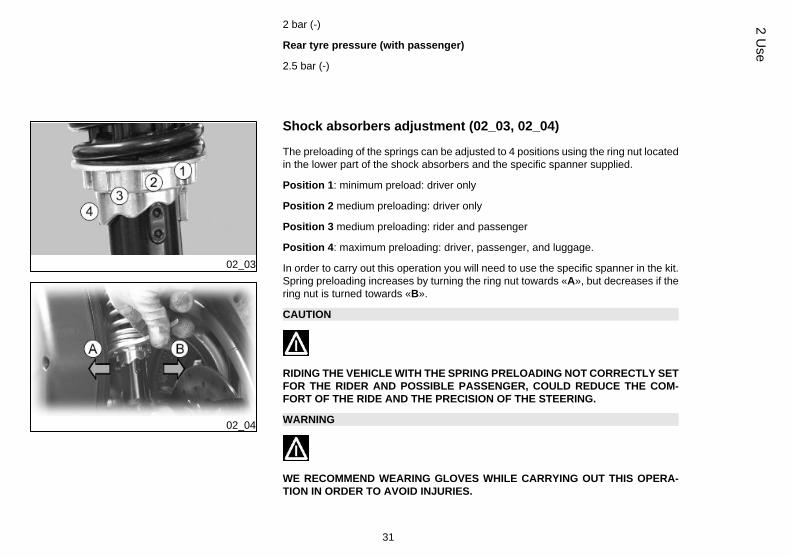
Shock absorbers adjustment (02_03, 02_04)
The preloading of the springs can be adjusted to 4 positions using the ring nut locatedin the lower part of the shock absorbers and the specific spanner supplied.
Position 1: minimum preload: driver only
Position 2 medium preloading: driver only
Position 3 medium preloading: rider and passenger
Position 4: maximum preloading: driver, passenger, and luggage.
In order to carry out this operation you will need to use the specific spanner in the kit.Spring preloading increases by turning the ring nut towards «A», but decreases if thering nut is turned towards «B».
CAUTION
RIDING THE VEHICLE WITH THE SPRING PRELOADING NOT CORRECTLY SETFOR THE RIDER AND POSSIBLE PASSENGER, COULD REDUCE THE COM-FORT OF THE RIDE AND THE PRECISION OF THE STEERING.
WARNING
WE RECOMMEND WEARING GLOVES WHILE CARRYING OUT THIS OPERA-TION IN ORDER TO AVOID INJURIES.
31
2 Use
WARNING
WE STRONGLY RECOMMEND NOT TO ADJUST BOTH SHOCK ABSORBERSWITH DIFFERENT PRELOADING
Running in
WARNING
DURING THE FIRST 1000 KM DO NOT RIDE THE VEHICLE OVER 80% OF ITSMAXIMUM SPEED. AVOID TWISTING THE THROTTLE GRIP FULLY OR KEEP-ING A CONSTANT SPEED ALONG LONG SECTIONS OF ROAD. AFTER THEFIRST 1000 KM, GRADUALLY INCREASE SPEED UNTIL REACHING THE MAX-IMUM PERFORMANCE.
02_05
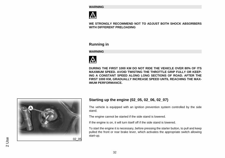
Starting up the engine (02_05, 02_06, 02_07)
The vehicle is equipped with an ignition prevention system controlled by the sidestand.
The engine cannot be started if the side stand is lowered.
If the engine is on, it will turn itself off if the side stand is lowered.
To start the engine it is necessary, before pressing the starter button, to pull and keeppulled the front or rear brake lever, which activates the appropriate switch allowingstart-up.
32
2 U
se

02_06
02_07
1. Rest the vehicle on its centre-stand, ensuring the rear wheel is not touching theground.
2. Keep the hand grip accelerator at the minimum.
3. Insert the key into the ignition switch «A» and turn to position «ON».
4. Make sure that the emergency stop switch «H» is set to «RUN» and the side standis up and not engaged.
5. Pull either the front, «L», or rear, «D», break lever and then press the starter button«N».
WARNING
THE AUTOMATIC TRANSMISSION MAKES THE REAR WHEEL TURN EVENWHEN THE THROTTLE IS SLIGHTLY TWISTED. RELEASE THE BRAKE CARE-FULLY AFTER STARTING, AND THEN ACCELERATE GRADUALLY.
CAUTION
DO NOT START-UP THE ENGINE IN CLOSED AREAS BECAUSE EXHAUSTGASES ARE TOXIC.
Precautions
CAUTION
NEVER STRESS THE ENGINE AT LOW TEMPERATURES IN ORDER TO AVOIDPOSSIBLE DAMAGE. BE CAREFUL NEVER TO EXCEED THE MAXIMUM SPEEDWHILE RUNNING DOWNHILL, IN ORDER TO AVOID DAMAGING THE ENGINE.
33
2 Use

IN ANY CASE, IN ORDER TO PRESERVE THE ENGINE FROM PROLONGED EX-CESSIVE REVOLUTIONS, THE REVOLUTION LIMITER WILL BE ACTIVATED IFTHE ENGINE SPEED EXCEEDS THE ESTABLISHED THRESHOLD.
WARNING
AFTER A LONG DISTANCE COVERED AT THE MAXIMUM SPEED, DO NOT STOPTHE ENGINE IMMEDIATELY, BUT LET IT RUN AT IDLE FOR A FEW SECONDS.
Difficult start up
In the rare case of flooding the engine, to facilitate start-up, it is possible to try to putthe vehicle into action with the gas hand grip partially or completely open. It is howevernecessary, once the engine is started, to take your vehicle to an Authorised ServiceCentre to determine the cause of this problem and to re-establish the vehicle properfunctioning.
02_08
Stopping the engine (02_08)
Fully untwist the throttle grip, then rotate the key in the switch «A » to «KEYOFF» (extractable key).
CAUTION
DUE TO THE HIGH TEMPERATURES THE CATALYTIC CONVERTER CANREACH, ALWAYS TAKE CARE, WHEN PARKING THE SCOOTER, THAT THEEXHAUST DOES NOT COME INTO CONTACT WITH FLAMMABLE MATERIALS,TO AVOID SERIOUS BURNS.
34
2 U
se
CAUTION
DO NOT SWITCH OFF THE ENGINE WHILE THE VEHICLE IS MOVING. UN-BURNED FUEL COULD ENTER THE CATALYTIC CONVERTER AND BURN,CAUSING IT TO OVERHEAT AND POSSIBLY DESTROYING IT.
WARNING
TO START AFTER A LONG STATIONARY PERIOD, OR IN SEVERE WEATHERCONDITIONS, FULLY TWIST THE THROTTLE 2÷3 TIMES BEFORE PRESSINGTHE STARTER BUTTON.
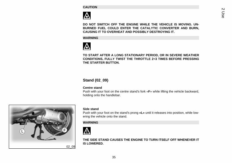
Stand (02_09)
Centre standPush with your foot on the centre stand's fork «F» while lifting the vehicle backward,holding onto the handlebar.
02_09
Side standPush with your foot on the stand's prong «L» until it releases into position, while low-ering the vehicle onto the stand.
WARNING
THE SIDE STAND CAUSES THE ENGINE TO TURN ITSELF OFF WHENEVER ITIS LOWERED.
35
2 Use

WARNING
TAMPERING MAY CAUSE SERIOUS ENGINE MALFUNCTION.
CAUTION
DUE TO THE HIGH TEMPERATURES THE CATALYTIC CONVERTER CANREACH, ALWAYS TAKE CARE, WHEN PARKING THE SCOOTER, THAT THEEXHAUST DOES NOT COME INTO CONTACT WITH FLAMMABLE MATERIALS,TO AVOID SERIOUS BURNS.
CAUTION
DO NOT SWITCH OFF THE ENGINE WHILE THE VEHICLE IS MOVING. UN-BURNED FUEL COULD ENTER THE CATALYTIC CONVERTER AND BURN,CAUSING IT TO OVERHEAT AND POSSIBLY DESTROYING IT.
Automatic transmission
To ensure simple, pleasurable riding, the vehicle is equipped with automatic trans-mission with regulator and centrifugal clutch. The system is designed to provide thebest performance (acceleration and consumption) while riding on both flat roads anduphill.
If you have to stop on an uphill slope (traffic lights, traffic jam, etc.) use only the braketo keep the vehicle still, leaving the engine running at idle speed. Using theengine to keep the vehicle still can cause the clutch to overheat, due to thefriction of the clutch mechanism itself against the clutch bell.
36
2 U
se
It is therefore recommended to avoid conditions of prolonged clutch slippage (otherthan those previously indicated) like driving uphill fully laden on steep slopes or startingoff with driver and passenger at slopes with steepness greater than 25%.
Observe the following precautions if the clutch overheats:
1. Do not continue riding in such conditions.
2. Let the clutch cool down with the engine at idle speed for a few minutes.
Safe driving
Some simple tips are provided below that will enable you to use your vehicle on a dailybasis in greater safety and peace of mind. Your skill and your mechanical knowledgeare the basis of safe riding. We recommend trying out the vehicle in traffic - free zones,in order to acquire a good knowledge of the vehicle it self.1. Before riding off, remember to put on your helmet and fasten it correctly.
2.Reduce speed on rough roads and drive with care.
3. After riding on a long stretch of wet road without using the brakes, braking can bepoor at the beginning. Given these conditions, it is a good idea to operate the brakesfrom time to time.
4. Do not brake hard on wet, dirt or slippery road surfaces.
5. Avoid riding off by mounting the scooter when resting on the support. In any case,the rear wheel should not be turning when in comes into contact with the ground, inorder to avoid abrupt departures.
6. When riding along roads covered by sand, mud, snow mixed with salt, etc. werecommend cleaning the brake disc frequently with a non-corrosive detergent in orderto prevent corrosive particles from building up in the holes, which may cause earlybrake pad wear.
37
2 Use
CAUTION
ALWAYS RIDE WITHIN YOUR LIMITS RIDING UNDER THE INFLUENCE OF AL-COHOL OR OTHER DRUGS AND CERTAIN MEDICATIONS IS EXTREMELY DAN-GEROUS.
CAUTION
ANY CHANGES TO THE VEHICLE PERFORMANCE AS WELL AS ALTERATIONSTO ORIGINAL STRUCTURAL PARTS IS STRICTLY FORBIDDEN BY LAW, ANDRENDERS THE VEHICLE NO LONGER CONFORMING TO THE APPROVED TYPEAND DANGEROUS FOR RIDING.
CAUTION
DO NOT ADJUST THE MIRRORS WHILE RIDING. THIS COULD CAUSE YOU TOLOOSE CONTROL OF THE VEHICLE.
WARNING
IN ORDER TO PREVENT ANY ACCIDENTS RIDE VERY CAREFULLY AFTERADDING ACCESSORIES AND WHILE CARRYING LUGGAGE. THE ADDITION OFACCESSORIES AND LUGGAGE CAN REDUCE YOUR SCOOTER STABILITYAND PERFORMANCE, AS WELL AS THE LEVEL OF SAFETY DURING USE.NEVER DRIVE THE SCOOTER EQUIPPED WITH ACCESSORIES AT A SPEEDHIGHER THAN 100 km/h (see section "SPARE PARTS AND ACCESSORIES").
38
2 U
se

BEVERLYCruiser 250ie
Chap. 03Maintenance
39

Engine oil level
In 4T engines, the engine oil is used to lubricate the distribution elements, the benchbearings and the thermal group. An insufficient quantity of oil can cause seriousdamage to the engine. In all four-stroke engines, a loss of efficiency in oil perform-ance and consumption should be considered normal. Consumption can particularlyreflect the conditions of use (i.e. when driving at 'full acceleration' all the time, oil con-sumption increases). In order to prevent any problems, we recommend checkingthe oil level any time you use the vehicle. The scooter is, however, equippedwith an oil pressure warning light on the instrument panel.
03_01
03_02
Engine oil level check (03_01, 03_02)
Every time the vehicle is used, visually inspect the level of the engine oil when theengine is cold (after completely unscrewing the oil cap/dipstick). The oil level shouldbe somewhere between the MAX and MIN index marks on the level rod; «A»; duringthe oil check, the vehicle must be resting on its centre stand on an even, horizontalsurface.
If the check is carried out after the vehicle has been used, and therefore with a hotengine, the level line will be lower; in order to carry out a correct check, wait at least10 minutes after the engine has been stopped so as to get the correct level.
40
3 M
aint
enan
ce
Engine oil top-up
Always check oil level before topping-up and add oil without exceeding the MAXlevel. Getting an oil level between the MIN and MAX levels requires ~ 200 cm³ of oil.Take your vehicle to an Authorised Service Centre to have the engine oil checkedand if necessary, topped-up as indicated in the scheduled maintenance table.
03_03
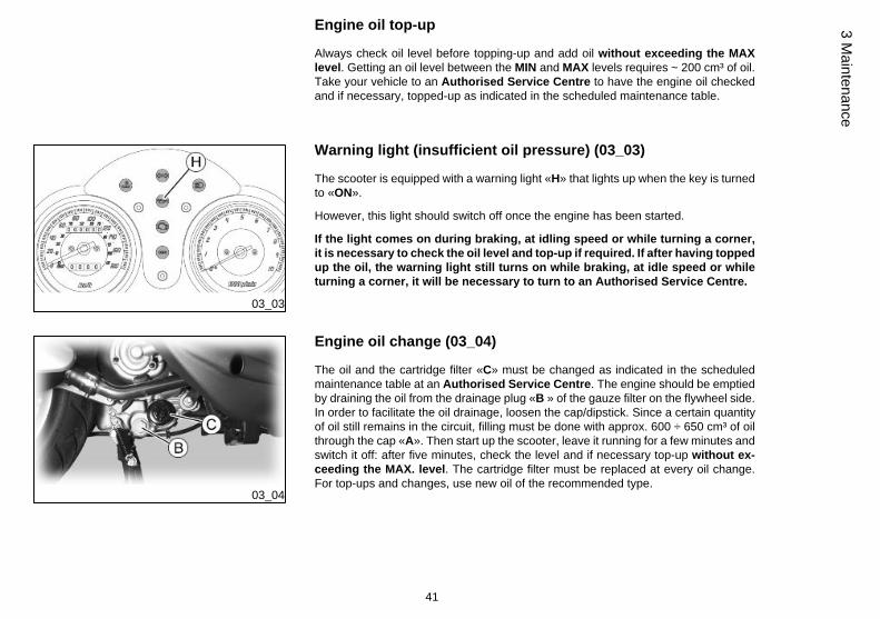
Warning light (insufficient oil pressure) (03_03)
The scooter is equipped with a warning light «H» that lights up when the key is turnedto «ON».
However, this light should switch off once the engine has been started.
If the light comes on during braking, at idling speed or while turning a corner,it is necessary to check the oil level and top-up if required. If after having toppedup the oil, the warning light still turns on while braking, at idle speed or whileturning a corner, it will be necessary to turn to an Authorised Service Centre.
03_04
Engine oil change (03_04)
The oil and the cartridge filter «C» must be changed as indicated in the scheduledmaintenance table at an Authorised Service Centre. The engine should be emptiedby draining the oil from the drainage plug «B » of the gauze filter on the flywheel side.In order to facilitate the oil drainage, loosen the cap/dipstick. Since a certain quantityof oil still remains in the circuit, filling must be done with approx. 600 ÷ 650 cm³ of oilthrough the cap «A». Then start up the scooter, leave it running for a few minutes andswitch it off: after five minutes, check the level and if necessary top-up without ex-ceeding the MAX. level. The cartridge filter must be replaced at every oil change.For top-ups and changes, use new oil of the recommended type.
41
3 Maintenance
WARNING
RUNNING THE ENGINE WITH INSUFFICIENT LUBRICATION OR WITH INADE-QUATE LUBRICANTS ACCELERATES THE WEAR AND TEAR OF THE MOVINGPARTS AND CAN CAUSE IRRETRIEVABLE DAMAGE.
WARNING
EXCESSIVE OIL LEVEL AT TOP-UPS CAN LEAD TO SCALE FORMATION ANDVEHICLE MALFUNCTION.
CAUTION
USED OILS CONTAIN SUBSTANCES HARMFUL TO THE ENVIRONMENT. FOROIL CHANGE, CONTACT AN AUTHORISED PIAGGIO SERVICE CENTRE, ASTHEY ARE EQUIPPED TO DISPOSE OF USED OILS IN AN ENVIRONMENTALLYFRIENDLY AND LEGAL WAY.
CAUTION
USING OILS OTHER THAN THOSE RECOMMENDED CAN SHORTEN THE LIFEOF THE ENGINE.
Recommended productsAGIP CITY HI TEC 4T
Engine oilSAE 5W-40, API SL, ACEA A3, JASO MA Synthetic oil
42
3 M
aint
enan
ce
03_05
03_06
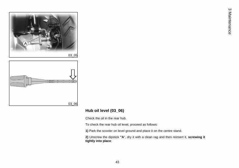
Hub oil level (03_06)
Check the oil in the rear hub.
To check the rear hub oil level, proceed as follows:
1) Park the scooter on level ground and place it on the centre stand.
2) Unscrew the dipstick "A", dry it with a clean rag and then reinsert it, screwing ittightly into place;
43
3 Maintenance
3) Remove the dipstick and check that the oil level is above the first notch from thebottom.
4) Screw the dipstick back in, checking that it is locked in place.
N.B.
THE REFERENCE MARKS ON THE HUB OIL LEVEL DIPSTICK, EXCEPT FORTHE ONE INDICATING THE "MAX" LEVEL, REFER TO OTHER MODELS BY THEMANUFACTURER AND HAVE NO SPECIFIC FUNCTION FOR THIS MODEL.
CAUTION
RIDING THE VEHICLE WITH INSUFFICIENT HUB LUBRICATION OR WITH CON-TAMINATED OR IMPROPER LUBRICANTS ACCELERATES THE WEAR ANDTEAR OF THE MOVING PARTS AND CAN CAUSE SERIOUS DAMAGE.
CAUTION
USED OILS CONTAIN SUBSTANCES HARMFUL TO THE ENVIRONMENT. FOROIL REPLACEMENT, CONTACT AN AUTHORISED SERVICE CENTRE, WHICHIS EQUIPPED TO DISPOSE OF USED OILS IN AN ENVIRONMENTALLY FRIEND-LY AND LEGAL WAY.
CAUTION
UPON REPLACING HUB OIL, AVOID THE OIL COMING INTO CONTACT WITHTHE REAR BRAKE DISC.
Recommended productsAGIP ROTRA 80W-90
Rear hub oil
44
3 M
aint
enan
ce

SAE 80W/90 Oil that exceeds the requirements of API GL3 specifications
CharacteristicTransmission oil
250 cm³
03_07
Tyres (03_07)
Check tyre pressure frequently. Tyres feature wear indicators; replace tyres as soonas these indicators become visible on the tyre tread. Also check that the tyres do notshow signs of splitting at the side or irregular tread wear; if this occurs, go to an au-thorised workshop or at least to a workshop equipped to perform the replacement.
CAUTION
TYRE PRESSURE SHOULD BE CHECKED WHEN TYRES ARE COLD.INCOR-RECT TYRE PRESSURE CAUSES ABNORMAL TYRE WEAR AND MAKES RID-ING DANGEROUS.
TYRES MUST BE REPLACED WHEN THE TREAD REACHES THE WEAR LIMITSSET FORTH BY LAW.
CharacteristicFront tyre pressure (with passenger)
2 bar (-)
Rear tyre pressure (with passenger)
2.5 bar (-)
45
3 Maintenance
03_08
03_09
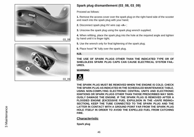
Spark plug dismantlement (03_08, 03_09)
Proceed as follows:
1. Remove the access cover over the spark plug on the right-hand side of the scooterand reach into the spark plug with your hand;
2. Disconnect spark plug HV wire cap «A» ;
3. Unscrew the spark plug using the spark plug wrench supplied;
4. When refitting, place the spark plug into the hole at the required angle and tightenby hand until it is finger tight;
5. Use the wrench only for final tightening of the spark plug;
6. Place hood "A" fully over the spark plug.
N.B.
THE USE OF SPARK PLUGS OTHER THAN THE INDICATED TYPE OR OFSHIELDLESS SPARK PLUG CAPS CAN CAUSE ELECTRICAL SYSTEM FAIL-URES.
WARNING
THE SPARK PLUG MUST BE REMOVED WHEN THE ENGINE IS COLD. CHECKTHE SPARK PLUG AS INDICATED IN THE SCHEDULED MAINTENANCE TABLE.USING NON-COMPLYING ELECTRONIC CENTRAL UNITS AND ELECTRONICIGNITIONS OR SPARK PLUGS OTHER THAN THOSE PRESCRIBED MAY SERI-OUSLY DAMAGE THE ENGINE. IF THE SPARK PLUG IS REMOVED AFTER AFLOODED ENGINE (EXCESSIVE FUEL EXPULSION IN THE «SAFE RIDING»SECTION), KEEP THE TUBE CONNECTED TO THE SPARK PLUG AND THELATTER IN CONTACT WITH A GROUND POINT FAR FROM THE SPARK PLUGHOLE ITSELF IN ORDER TO AVOID THE EXPELLED FUEL FROM CATCHINGFIRE.
CharacteristicSpark plug
46
3 M
aint
enan
ce
CHAMPION RG 4 PHP
Electrode gap
0.7-0.8 mm
03_10
03_11
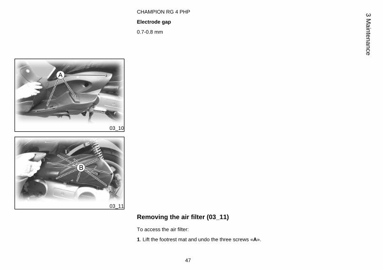
Removing the air filter (03_11)
To access the air filter:
1. Lift the footrest mat and undo the three screws «A».
47
3 Maintenance

2. Remove the right footrest to have access to the nine screws «B» and unscrew them.
3. Remove the air filter cover «C».
Air filter cleaning
1. Wash the sponge with water and neutral soap.
2. Dry it with a clean cloth and small blasts of compressed air.
3. Impregnate the sponge with a mixture of 50% petrol and 50% specified oil.
4. Gently squeeze the filter element, let it drip and then refit it.
CAUTION
IF THE VEHICLE IS USED ON DUSTY ROADS, IT IS NECESSARY TO SERVICETHE AIR FILTER MORE OFTEN TO AVOID DAMAGING THE ENGINE.
Recommended productsAGIP FILTER OIL
Oil for air filter spongeMineral oil with specific additives for increased adhesiveness
48
3 M
aint
enan
ce
03_12
03_13
03_14
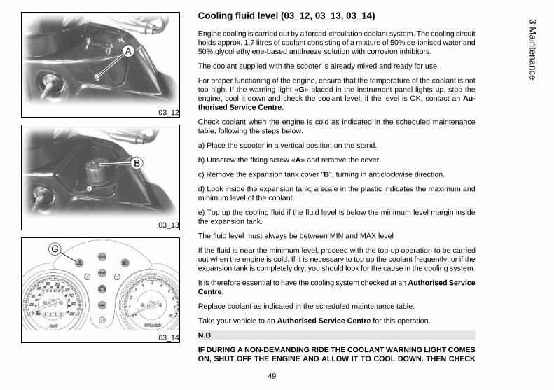
Cooling fluid level (03_12, 03_13, 03_14)
Engine cooling is carried out by a forced-circulation coolant system. The cooling circuitholds approx. 1.7 litres of coolant consisting of a mixture of 50% de-ionised water and50% glycol ethylene-based antifreeze solution with corrosion inhibitors.
The coolant supplied with the scooter is already mixed and ready for use.
For proper functioning of the engine, ensure that the temperature of the coolant is nottoo high. If the warning light «G» placed in the instrument panel lights up, stop theengine, cool it down and check the coolant level; if the level is OK, contact an Au-thorised Service Centre.
Check coolant when the engine is cold as indicated in the scheduled maintenancetable, following the steps below.
a) Place the scooter in a vertical position on the stand.
b) Unscrew the fixing screw «A» and remove the cover.
c) Remove the expansion tank cover "B", turning in anticlockwise direction.
d) Look inside the expansion tank; a scale in the plastic indicates the maximum andminimum level of the coolant.
e) Top up the cooling fluid if the fluid level is below the minimum level margin insidethe expansion tank.
The fluid level must always be between MIN and MAX level
If the fluid is near the minimum level, proceed with the top-up operation to be carriedout when the engine is cold. If it is necessary to top up the coolant frequently, or if theexpansion tank is completely dry, you should look for the cause in the cooling system.
It is therefore essential to have the cooling system checked at an Authorised ServiceCentre.
Replace coolant as indicated in the scheduled maintenance table.
Take your vehicle to an Authorised Service Centre for this operation.
N.B.
IF DURING A NON-DEMANDING RIDE THE COOLANT WARNING LIGHT COMESON, SHUT OFF THE ENGINE AND ALLOW IT TO COOL DOWN. THEN CHECK
49
3 Maintenance
THE COOLANT LEVEL; IF THE LEVEL IS NOT CORRECT, CONTACT AN AU-THORISED SERVICE CENTRE.
WARNING
TO AVOID THE RISK OF SCALDING, DO NOT UNSCREW THE EXPANSIONTANK COVER WHILE THE ENGINE IS STILL HOT.
WARNING
IN ORDER TO AVOID HARMFUL FLUID LEAKS WHILE RIDING, IT IS IMPORTANTTO MAKE SURE THAT THE LEVEL NEVER EXCEEDS THE MAXIMUM VALUE.
IN ORDER TO GUARANTEE THE PROPER FUNCTION OF THE ENGINE, IT ISNECESSARY TO KEEP THE RADIATOR GRILLE CLEAN.
03_15
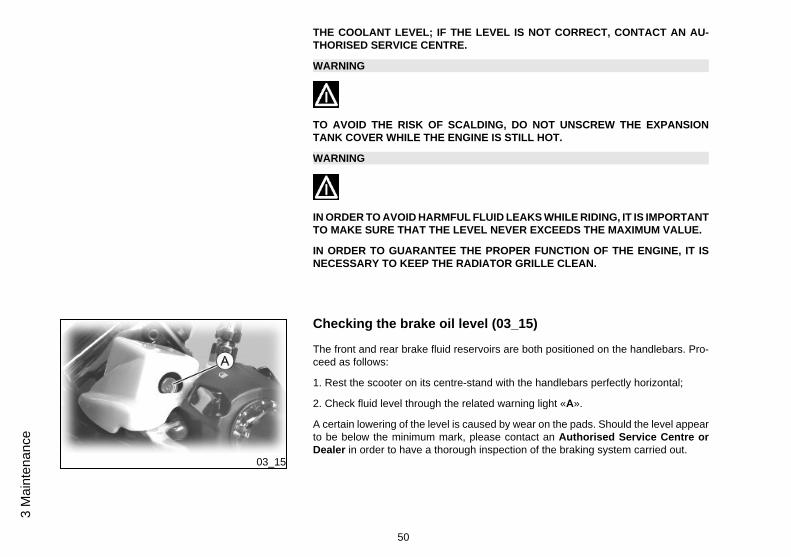
Checking the brake oil level (03_15)
The front and rear brake fluid reservoirs are both positioned on the handlebars. Pro-ceed as follows:
1. Rest the scooter on its centre-stand with the handlebars perfectly horizontal;
2. Check fluid level through the related warning light «A».
A certain lowering of the level is caused by wear on the pads. Should the level appearto be below the minimum mark, please contact an Authorised Service Centre orDealer in order to have a thorough inspection of the braking system carried out.
50
3 M
aint
enan
ce

03_16
03_17
Braking system fluid top up (03_16, 03_17)
Instructions refer to one braking system only, but they are valid for both.
Remove the rear-view mirror undoing the nut «A» and remove the plastic cover «B».Unscrew the two screws «C», remove the fuel tank cap and the intermediate rubbermembrane, and top-up the brake fluid level only with the recommend brake fluid typeand without exceeding the maximum level.
Under standard climatic conditions, replace coolant as indicated in the scheduledmaintenance table. This operation must be carried out by trained technicians; takeyour scooter to an authorised Service Centre or Dealer.
WARNING
ONLY USE DOT 4 CLASS BRAKE FLUIDS. COOLING SYSTEM FLUIDS AREHIGHLY CORROSIVE. MAKE SURE THAT IT DOES NOT COME INTO CONTACTWITH THE PAINTWORK.
CAUTION
AVOID CONTACT OF BRAKE FLUID WITH EYES, SKIN, AND CLOTHING. INCASE OF CONTACT, RINSE WITH WATER. THE BRAKING CIRCUIT FLUID ISHYGROSCOPIC, THAT IS, IT ABSORBS HUMIDITY FROM THE SURROUNDINGAIR. IF THE HUMIDITY IN THE BRAKING FLUID EXCEEDS A CERTAIN VALUE,IT WILL LEAD TO INEFFICIENT BRAKING. NEVER USE BRAKING FLUID KEPTIN CONTAINERS THAT HAVE ALREADY BEEN OPENED, OR PARTIALLY USED.
Recommended productsAGIP BRAKE 4
Brake fluidFMVSS DOT 4 Synthetic fluid
51
3 Maintenance

03_18
Battery (03_18)
To access the battery, proceed as follows:
1. rest the scooter on its centre stand.
2. open the saddle
3. Remove retainer "A" and cover "B".
4. release the battery retaining ring.
The battery is the electrical device that requires the most frequent inspections anddiligent maintenance.
The main points of maintenance to be observed are as follows:
WARNING
DO NOT DISCONNECT THE BATTERY CABLES WITH THE ENGINE RUNNING,THIS CAN CAUSE PERMANENT DAMAGE TO THE VEHICLE ELECTRONIC CON-TROL UNIT.
52
3 M
aint
enan
ce

WARNING
THE ELECTROLYTE CONTAINS SULPHURIC ACID: AVOID CONTACT WITHEYES, SKIN AND CLOTHES. IN THE CASE OF ACCIDENTAL CONTACT, RINSEWITH ABUNDANT OF WATER AND CONSULT A DOCTOR.
WARNING
SPENT BATTERIES ARE HARMFUL FOR THE ENVIRONMENT. COLLECTIONAND DISPOSAL SHOULD BE CARRIED OUT IN COMPLIANCE WITH CURRENTREGULATIONS.
CharacteristicBattery
SEALED 12V / 12Ah BATTERY
Use of a new battery
Position the battery in its housing and connect the positive lead «+» first and then thenegative one «-». Check the voltage
CAUTION
DO NOT REVERSE THE POLARITY: RISK OF SHORT CIRCUIT AND DAMAGETO THE ELECTRICAL SYSTEM.
53
3 Maintenance

03_19
Long periods of inactivity (03_19)
Battery performance will decrease if the vehicle is not used for a long time. This is theresult of the natural phenomenon of battery discharging plus residual absorption byvehicle components with constant power consumption. Poor battery performance mayalso be due to environmental conditions and the cleanness of the poles. In order toavoid difficult starts and/or irreversible damage to the battery, follow any of thesesteps:
- At least once a month start the engine and run it slightly above idle speed for 10-15minutes. This keeps all the engine components, as well as the battery, in good workingorder.
- Take your vehicle to a garage (as indicated in the "Vehicle not used for extendedperiods" section) to have the battery removed. Have the battery cleaned, charged fullyand stored in a dry, ventilated place. Recharge at least once every two months.
CAUTION
THE BATTERY MUST BE CHARGED WITH A CURRENT EQUAL TO 1/10 OF THERATED CAPACITY OF THE BATTERY AND FOR NOT LONGER THAN 10 HOURS.CONTACT AN AUTHORISED SERVICE CENTRE TO CARRY OUT THIS OPERA-TION SAFELY. WHEN REFITTING THE BATTERY MAKE SURE THE LEADS ARECORRECTLY CONNECTED TO THE TERMINALS.
Fuses (03_20, 03_21, 03_22)
The electrical system is equipped with:
1. Six protective fuses «A» located inside the side panel on the right-hand side;
2. Four protective fuses «B» located inside the compartment on the upper left-handside.
The chart shows the position and characteristics of the fuses in the vehicle.
54
3 M
aint
enan
ce

CAUTION
BEFORE REPLACING A BLOWN FUSE, FIND AND SOLVE THE FAILURE THATCAUSED IT TO BLOW. NEVER TRY TO REPLACE THE FUSE WITH ANY OTHERMATERIAL (E.G., A PIECE OF ELECTRIC WIRE).
CAUTION
MODIFICATIONS OR REPAIRS TO THE ELECTRICAL SYSTEM, PERFORMEDINCORRECTLY OR WITHOUT STRICT ATTENTION TO THE TECHNICAL SPEC-IFICATIONS OF THE SYSTEM, CAN CAUSE ERRORS IN FUNCTIONING ANDRISK OF FIRE.
FUSESFuse No. 1 Capacity:7.5 A
Protected circuits:Power supplyfrom battery for injection electroniccontrol unit.
Fuse No. 2 Capacity:7.5 A
Protected circuits:Power supplyfrom battery for immobilizer andarrows.
Fuse No. 3 Capacity:10 A
55
3 Maintenance
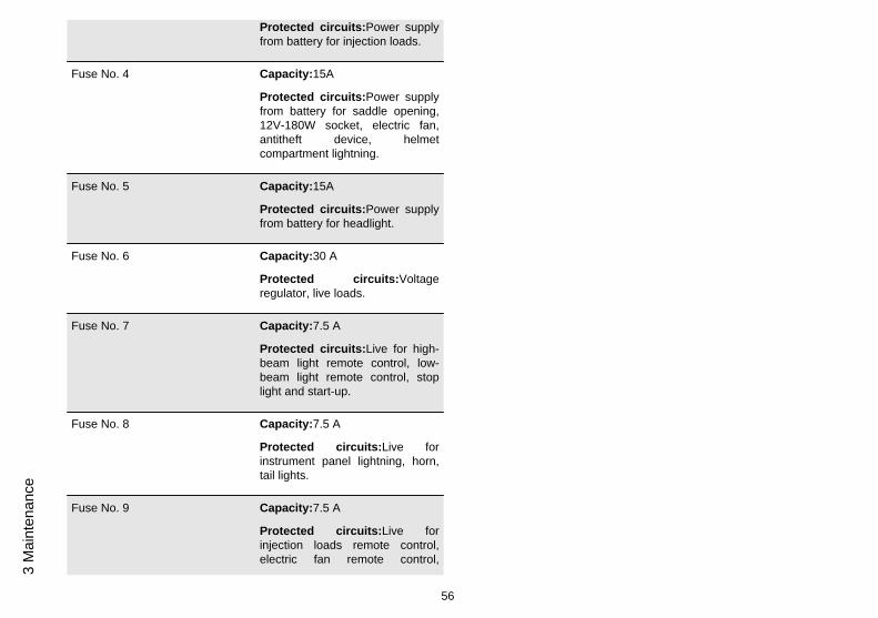
Protected circuits:Power supplyfrom battery for injection loads.
Fuse No. 4 Capacity:15A
Protected circuits:Power supplyfrom battery for saddle opening,12V-180W socket, electric fan,antitheft device, helmetcompartment lightning.
Fuse No. 5 Capacity:15A
Protected circuits:Power supplyfrom battery for headlight.
Fuse No. 6 Capacity:30 A
Protected circuits:Voltageregulator, live loads.
Fuse No. 7 Capacity:7.5 A
Protected circuits:Live for high-beam light remote control, low-beam light remote control, stoplight and start-up.
Fuse No. 8 Capacity:7.5 A
Protected circuits:Live forinstrument panel lightning, horn,tail lights.
Fuse No. 9 Capacity:7.5 A
Protected circuits:Live forinjection loads remote control,electric fan remote control,
56
3 M
aint
enan
ce

immobilizer, injection electroniccontrol unit.
Fuse No. 10 Capacity:7.5 A
Protected circuits:Live for turnindicators, antitheft device,instrument panel, fuel gauge.
03_20
03_21
57
3 Maintenance

03_22
LIST OF BULBSHigh-/low-beam bulb Type: Halogen (H4)
Quantity: 1
Power: 12V - 55/60W
Front tail light bulb Type: All glass
Quantity: 1
Power: 12V - 5W
Turn indicator bulbs Type: Spherical
Quantity: 4
Power: 12V - 10W
Rear tail light bulb Type: All glass
Quantity: 2
58
3 M
aint
enan
ce

Power: 12V - 3W
Stop light bulb Type: Spherical
Quantity: 1
Power: 12V - 10W
Instrument panel lighting bulb Type: All glass
Quantity: 5
Power: 12V - 1.2W
Helmet compartment light bulb Type: Cylindrical
Quantity: 1
Power: 12V - 5W
License plate light bulb Type: All glass
Quantity: 1
Power: 12V - 5W
03_23
Front light group (03_23, 03_24)
To access the bulbs, undo the screw «A» and remove the headlight assembly col-lecting the shim washer and the washer.
To replace the high-/low-beam headlight bulb «B», detach the connector, remove therubber protection, release the retaining clip and take out the bulb.
To replace the tail light bulb «C», take out the rubber bulb holder and slide off the bulb.
59
3 Maintenance

03_24
03_25
03_26
Headlight adjustment (03_25, 03_26, 03_27)
In order to carry out the vertical adjustment of the light beam:
1. Place the vehicle, in running order and with the tyres inflated to the prescribedpressure, on a flat surface 10 m away from a half-lit white screen, and make sure thatthe longitudinal axis of the scooter is perpendicular to the screen.
2. Turn on the headlight and check that the borderline of the beam projected on thescreen is not higher than 9/10 or lower than 7/10 of the height of the centre of theheadlight from the ground.
3. Otherwise, loosen the screws «D» and rotate the light until the optimal orientationis obtained.
60
3 M
aint
enan
ce
03_27
03_28
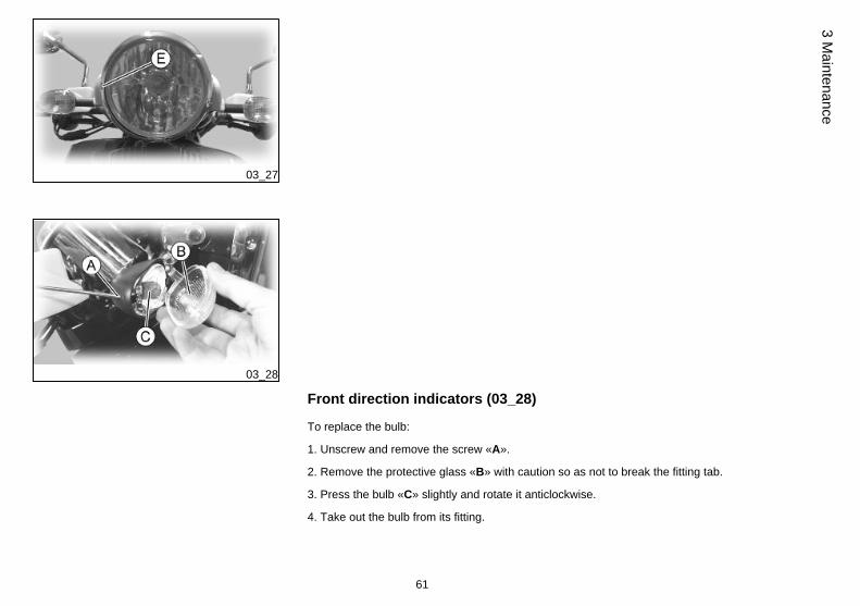
Front direction indicators (03_28)
To replace the bulb:
1. Unscrew and remove the screw «A».
2. Remove the protective glass «B» with caution so as not to break the fitting tab.
3. Press the bulb «C» slightly and rotate it anticlockwise.
4. Take out the bulb from its fitting.
61
3 Maintenance

5. Fit a new bulb of equal type making sure the two guiding pins slide into their slotsin the bulb holder.
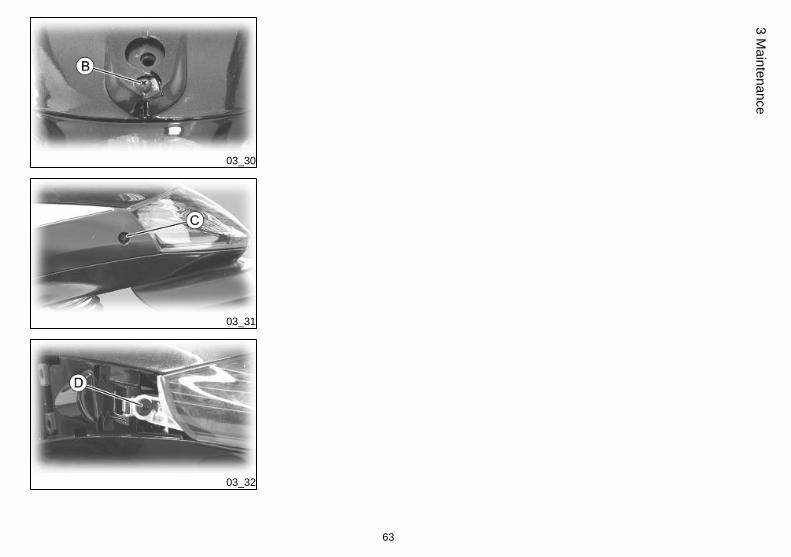
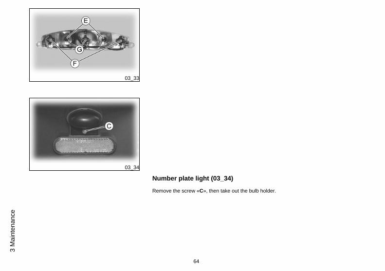
Rear optical unit (03_29, 03_30, 03_31, 03_32, 03_33)
To access the bulbs:
1. Remove the battery cover.
2. Remove the luggage rack plastic cover by acting on the screw «A» and unscrewthe three fixing screws of the luggage rack.
3. Remove screw «B».
4. Remove side fairings by undoing screws «C» paying attention not to damage theretaining straps.
5. Remove both screws «B » and take out the rear light unit.
03_29
To replace the tail light bulbs «E», take out the rubber bulb holder from its fitting andslide off the bulb.
To replace turn indicator bulbs «F» and the stop light bulb «G», take out the bulb holderpressing the plastic tongues and turning the bulb anticlockwise.
62
3 M
aint
enan
ce
03_30
03_31
03_32
63
3 Maintenance
03_33
03_34
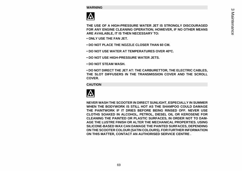
Number plate light (03_34)
Remove the screw «C», then take out the bulb holder.
64
3 M
aint
enan
ce

03_35
Helmet compartment lighting bulb (03_35)
Open the helmet compartment, take out the snap-on transparent glass and replacethe bulb.
03_36
Rear-view mirrors (03_36)
Adjust the mirrors by applying slight pressure to the side of the mirror to move it to thedesired position.
65
3 Maintenance

03_37
Front and rear disc brake (03_37)
The brake disc and pad wear is automatically compensated, therefore it has no effecton the functioning of the front and rear brakes. For this reason it is not necessary toadjust the brakes. An excessively elastic brake lever stroke may indicate the presenceof air in the braking circuit or a failure in the braking system. In this case, mainly dueto the importance of brakes to guarantee safe riding conditions, the vehicle should betaken to an Authorised Service Centre or Dealer.
CAUTION
THE BRAKING ACTION SHOULD BEGIN AFTER ABOUT 1/3 OF THE BRAKELEVER STROKE.
CAUTION
HAVE THE BRAKE PADS CHECKED BY THE DEALER ACCORDING TO THECHECKS SPECIFIED IN THE SCHEDULED MAINTENANCE TABLE. HOWEVER,IN THE EVENT OF NOISES COMING FROM THE FRONT AND/OR REAR BRAKESYSTEM DURING OPERATION, IT IS ADVISABLE TO HAVE THE BRAKE SYS-TEM CHECKED BY A PIAGGIO DEALER OR AUTHORISED SERVICE CENTRE.AFTER REPLACING THE BRAKE PADS, DO NOT USE THE SCOOTER BEFOREHAVING USED THE BRAKE LEVER SEVERAL TIMES IN ORDER TO ALLOW THEPISTONS TO SETTLE AND THE LEVER STROKE TO BE SET TO THE CORRECTPOSITION.
CAUTION
THE PRESENCE OF SAND, MUD, SNOW MIXED WITH SALT, ETC. ON THEROAD, CAN DRASTICALLY REDUCE THE DURATION OF THE BRAKE PADS. IN
66
3 M
aint
enan
ce

ORDER TO AVOID THIS, WE RECOMMEND WASHING THE VEHICLE FRE-QUENTLY WHEN RIDING IN THESE ROAD CONDITIONS.
Puncture
The vehicle is equipped with Tubeless tyres (without inner tubes). In the event of apuncture, contrary to the situation with a tyre with inner tube, the tyre deflates moreslowly, resulting in a greater steering safety. A flat tyre can be repaired with an emer-gency «inflate and repair» spray. For a final repair, take your vehicle to an AuthorisedService Centre or Dealer. The replacement of a type involves removing the wheel inquestion. Take your vehicle to an Authorised Service Centre or Dealer for theseoperations.
CAUTION
TO USE THE "INFLATE AND REPAIR" SPRAY PROPERLY FOLLOW THE IN-STRUCTIONS ON THE PACKAGING.
WARNING
THE WHEELS FITTED WITH TYRES SHOULD ALWAYS BE BALANCED. RIDINGTHE VEHICLE WITH VERY LOW TYRE PRESSURE OR WITH INCORRECTLYBALANCED TYRES CAN LEAD TO DANGEROUS STEERING VIBRATIONS.
67
3 Maintenance

03_38
Periods of inactivity (03_38)
We recommend carrying out the following operations:
1. Clean the scooter thoroughly and then cover it with a canvas;
2. With the engine off and the piston in the bottom dead centre position, remove thespark plug, and pour into its hole 1 t0 2 cc of the recommended oil. Operate the starterbutton 1-2 times for roughly 1 second to turn the engine over slowly, then insert thespark plug again;
3. Ensure that the fuel tank is at least half full (in order to ensure the total im-mersion of the fuel pump); spread antirust grease on the unpainted metal parts;keep the wheels lifted above the ground by resting the chassis on two wooden wedges;4. As regards the battery, follow the instructions in the "Battery" section.
Recommended productsAGIP CITY HI TEC 4T
Oil to lubricate flexible transmissions (throttle control)Oil for 4-stroke engines
Cleaning the vehicle
In order to soften the dirt and mud deposited on the painted surfaces, use a low pres-sure jet of water. Once softened, mud and dirt must be removed with a soft spongefor bodywork soaked in lots of water and "shampoo" (2-4% of car shampoo in water).Then rinse abundantly with water, and dry with a shammy cloth. Any polishing withsilicon wax must always be preceded by washing
CAUTION
DETERGENTS CAN POLLUTE WATER. THE VEHICLE MUST BE WASHED AT AWASH STATION EQUIPPED WITH A SPECIAL WATER PURIFICATION SYSTEM.
68
3 M
aint
enan
ce
WARNING
THE USE OF A HIGH-PRESSURE WATER JET IS STRONGLY DISCOURAGEDFOR ANY ENGINE CLEANING OPERATION; HOWEVER, IF NO OTHER MEANSARE AVAILABLE, IT IS THEN NECESSARY TO:• ONLY USE THE FAN JET.
• DO NOT PLACE THE NOZZLE CLOSER THAN 60 CM.
• DO NOT USE WATER AT TEMPERATURES OVER 40ºC.
• DO NOT USE HIGH-PRESSURE WATER JETS.
• DO NOT STEAM WASH.
• DO NOT DIRECT THE JET AT: THE CARBURETTOR, THE ELECTRIC CABLES,THE SLOT DIFFUSERS IN THE TRANSMISSION COVER AND THE SCROLLCOVER.
CAUTION
NEVER WASH THE SCOOTER IN DIRECT SUNLIGHT, ESPECIALLY IN SUMMERWHEN THE BODYWORK IS STILL HOT AS THE SHAMPOO COULD DAMAGETHE PAINTWORK IF IT DRIES BEFORE BEING RINSED OFF. NEVER USECLOTHS SOAKED IN ALCOHOL, PETROL, DIESEL OIL OR KEROSENE FORCLEANING THE PAINTED OR PLASTIC SURFACES, IN ORDER NOT TO DAM-AGE THE LUSTRE FINISH OR ALTER THE MECHANICAL PROPERTIES. USINGSILICONE-BASED WAX CAN DAMAGE THE PAINTED SURFACES, DEPENDINGON THE SCOOTER COLOUR (SATIN COLOURS). FOR FURTHER INFORMATIONON THIS MATTER, CONTACT AN AUTHORISED SERVICE CENTRE .
69
3 Maintenance

WARNING
IN ORDER TO MAINTAIN PROPER CLEANING AND BRILLIANCE OF THE MUF-FLER, WE RECOMMEND THE USE OF A PRODUCT SPECIFICALLY FORCHROME-PLATED SURFACES
USE A SPECIFIC PASTE, ORDERED UNDER CODE 602683M FROM OUR DEAL-ER NETWORK, TO POLISH STAINLESS STEEL MUFFLERS.
STARTING FAILUREEmergency switch in «OFF» Set the switch back to «ON»
Fuse blown Replace the blown fuse and havethe scooter checked by anAuthorised Service Centre.
STARTING DIFFICULTIES (SEE SECTION «START-UPPROBLEMS»)
Lack of fuel in tank. Refuelling
Injection system fault Contact an Authorised ServiceCentre
Fuel pump fault Contact an Authorised ServiceCentre
70
3 M
aint
enan
ce

Battery flat Recharge the battery.
* IMPORTANT: DO NOT USE THE SCOOTER TO THE COMPLETEEXHAUSTION OF THE FUEL; IN THE EVENT THAT THIS SHOULDOCCUR, DO NOT ATTEMPT TO START THE ENGINE. TURN THEKEY SWITCH TO "OFF" AND TOP-UP THE TANK AS SOON ASPOSSIBLE. THE FAILURE TO FOLLOW THESE GUIDELINESCOULD CAUSE DAMAGE TO THE FUEL PUMP AND/OR THECATALYTIC CONVERTER.
IGNITION PROBLEMFaulty spark plug Contact an Authorised Service
Centre
Faulty ignition / injection controlunit. Due to the presence of highvoltage, this check should only becarried out by an expert.
Contact an Authorised ServiceCentre
LACK OF COMPRESSIONLoose spark plug. Screw in the spark plug tightly
Cylinder head loose, piston gasrings worn.
Contact an Authorised ServiceCentre
Valve stuck Contact an Authorised ServiceCentre
71
3 Maintenance

HIGH CONSUMPTION AND LOW PERFORMANCEClogged or dirty air filter Try to blow out with compressed
air, otherwise replace the filter
INSUFFICIENT BRAKINGGreasy disc. Worn pads. Faultybraking system. Presence of air inthe front and rear brake circuit.
Contact an Authorised ServiceCentre
INEFFICIENT SUSPENSIONSShock absorber fault, oil leak, endbuffer damaged; shock absorberpreloading incorrectly set
Contact an Authorised ServiceCentre
IRREGULAR AUTOMATIC TRANSMISSIONVariators and/or transmission beltdamaged
Contact an Authorised ServiceCentre
72
3 M
aint
enan
ce

BEVERLYCruiser 250ie
Chap. 04Technical data
73
04_01
74
4 Te
chni
cal d
ata
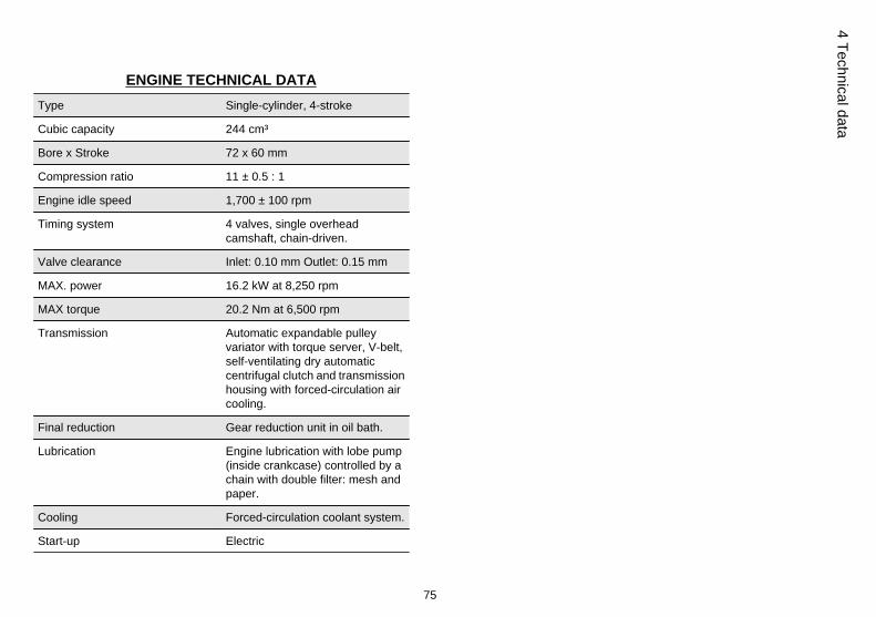
ENGINE TECHNICAL DATAType Single-cylinder, 4-stroke
Cubic capacity 244 cm³
Bore x Stroke 72 x 60 mm
Compression ratio 11 ± 0.5 : 1
Engine idle speed 1,700 ± 100 rpm
Timing system 4 valves, single overheadcamshaft, chain-driven.
Valve clearance Inlet: 0.10 mm Outlet: 0.15 mm
MAX. power 16.2 kW at 8,250 rpm
MAX torque 20.2 Nm at 6,500 rpm
Transmission Automatic expandable pulleyvariator with torque server, V-belt,self-ventilating dry automaticcentrifugal clutch and transmissionhousing with forced-circulation aircooling.
Final reduction Gear reduction unit in oil bath.
Lubrication Engine lubrication with lobe pump(inside crankcase) controlled by achain with double filter: mesh andpaper.
Cooling Forced-circulation coolant system.
Start-up Electric
75
4 Technical data

Ignition Electronic inductive dischargeignition, high efficiency, withseparate HV coil.
Ignition advance α/N three-dimensional mapmanaged by control unit
Spark plug CHAMPION RG 4 PHP
Alternative spark plug -
Fuel supply Electronic injection with Ø 32-mmthrottle body and electric fuelpump.
Fuel Unleaded petrol (95 RON)
Exhaust muffler Absorption-type exhaust mufflerwith a 3-way catalytic converterand lambda probe.
Emission regulations EURO 3
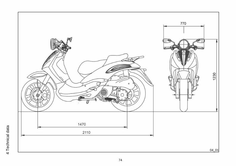
VEHICLE TECHNICAL DATAChassis Tubular and sheet steel.
Front suspension Hydraulic telescopic fork with Ø 35-mm stem
Rear suspension Two double-acting shockabsorbers, adjustable to fourpositions at preloading.
Front brake Ø 260-mm disc brake withhydraulic control activated byhandlebar right lever.
76
4 Te
chni
cal d
ata
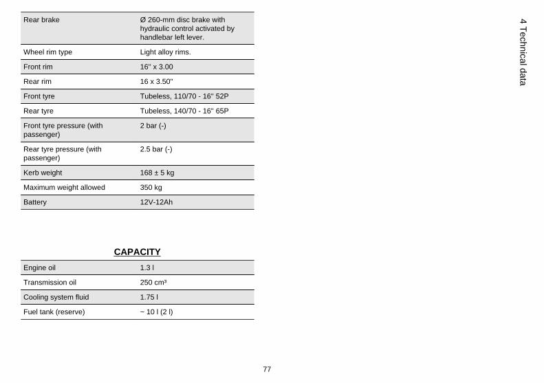
Rear brake Ø 260-mm disc brake withhydraulic control activated byhandlebar left lever.
Wheel rim type Light alloy rims.
Front rim 16'' x 3.00
Rear rim 16 x 3.50''
Front tyre Tubeless, 110/70 - 16'' 52P
Rear tyre Tubeless, 140/70 - 16'' 65P
Front tyre pressure (withpassenger)
2 bar (-)
Rear tyre pressure (withpassenger)
2.5 bar (-)
Kerb weight 168 ± 5 kg
Maximum weight allowed 350 kg
Battery 12V-12Ah
CAPACITYEngine oil 1.3 l
Transmission oil 250 cm³
Cooling system fluid 1.75 l
Fuel tank (reserve) ~ 10 l (2 l)
77
4 Technical data

Kit equipment
One box-spanner; one lever for box-spanner; one twin screwdriver; one specialwrench for adjusting rear shock absorbers. The tools are stored in the helmet com-partment.
78
4 Te
chni
cal d
ata

BEVERLYCruiser 250ie
Chap. 05Spare parts and
accessories
79

05_01
Warnings (05_01)
WARNING
TO PREVENT ACCIDENTS AND TO GUARANTEE PROPER STABILITY, PER-FORMANCE AND SAFETY, RIDE THE VEHICLE VERY CAREFULLY WHEN IT ISFITTED WITH ACCESSORIES OR WITH UNUSUAL LOADS.
WARNING
IT IS ALSO RECOMMENDED THAT "ORIGINAL PIAGGIO SPARE PARTS" BEUSED, AS THESE ARE THE ONLY ONES OFFERING YOU THE SAME QUALITYGUARANTEE AS THOSE INITIALLY FITTED ON THE SCOOTER. THE USE OFNON-ORIGINAL SPARE PARTS RENDERS THE WARRANTY VOID.
WARNING
PIAGGIO MARKETS ITS OWN LINE OF ACCESSORIES THAT ARE RECOG-NISED AND GUARANTEED FOR USE. IT IS THEREFORE ESSENTIAL, IN ORDERTO CHOOSE AND MOUNT THE ACCESSORIES CORRECTLY, TO CONTACT ANAUTHORISED DEALER OR SERVICE CENTRE. THE USE OF NON-ORIGINALACCESSORIES MAY AFFECT THE STABILITY AND OPERATION OF YOUR VE-HICLE AND REDUCE SAFETY LEVELS WITH POTENTIAL RISKS FOR THERIDER.
80
5 Sp
are
parts
and
acc
esso
ries

WARNING
NEVER RIDE THE SCOOTER EQUIPPED WITH ACCESSORIES (TOP BOX AND/OR WINDSHIELD) AT A SPEED HIGHER THAN 100 km/h.
THE SCOOTER CAN BE RIDDEN AT A HIGHER SPEED WITHOUT THE ACCES-SORIES MENTIONED BEFORE WITHIN THE LIMITS ESTABLISHED BY LAW.
IF THERE SHOULD BE NON-PIAGGIO ACCESSORIES INSTALLED, OR AN AB-NORMAL LOAD, OR IF THE SCOOTER IS NOT IN A GENERALLY GOOD CON-DITION, OR WHENEVER WEATHER CONDITIONS DEMAND IT, SPEED SHOULDBE REDUCED FURTHER.
WARNING
BE EXTREMELY CAREFUL WHEN INSTALLING AND REMOVING THE MECHAN-ICAL ANTI-THEFT DEVICE ON THE VEHICLE ( U-SHAPED PADLOCK, DISKBLOCK, ETC.).
MAINLY NEAR THE BRAKE PIPES, TRANSMISSIONS AND/OR ELECTRIC CA-BLES, AN INCORRECT INSTALLATION OR REMOVAL OF THE ANTI-THEFTDEVICE AS WELL AS LEAVING IT ON BEFORE STARTING THE VEHICLE CANSERIOUSLY DAMAGE ITS COMPONENTS, COMPROMISE THE CORRECTFUNCTIONING OF THE VEHICLE AND USERS' SAFETY.
81
5 Spare parts and accessories

82
5 Sp
are
parts
and
acc
esso
ries

BEVERLYCruiser 250ie
Chap. 06Programmedmaintenance
83
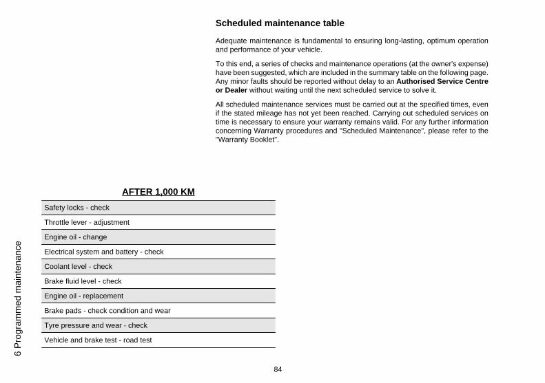
Scheduled maintenance table
Adequate maintenance is fundamental to ensuring long-lasting, optimum operationand performance of your vehicle.
To this end, a series of checks and maintenance operations (at the owner's expense)have been suggested, which are included in the summary table on the following page.Any minor faults should be reported without delay to an Authorised Service Centreor Dealer without waiting until the next scheduled service to solve it.
All scheduled maintenance services must be carried out at the specified times, evenif the stated mileage has not yet been reached. Carrying out scheduled services ontime is necessary to ensure your warranty remains valid. For any further informationconcerning Warranty procedures and "Scheduled Maintenance", please refer to the"Warranty Booklet".
AFTER 1,000 KMSafety locks - check
Throttle lever - adjustment
Engine oil - change
Electrical system and battery - check
Coolant level - check
Brake fluid level - check
Engine oil - replacement
Brake pads - check condition and wear
Tyre pressure and wear - check
Vehicle and brake test - road test
84
6 Pr
ogra
mm
ed m
aint
enan
ce

Hub oil - change
Steering - Check
AFTER 5,000 KM; 25,000 KM; 35,000 KM; 55,000 KM;65,000 KM
Engine oil - level check/ top-up
Brake pads - check condition and wear
Centre stand - lubrication
AFTER 10,000 KM 50,000 KM 70,000 KMSafety locks - check
Throttle lever - adjustment
Air filter - clean
Engine oil - change
Electrical system and battery - check
Coolant level - check
Brake fluid level - check
Engine oil - replacement
Brake pads - check condition and wear
Sliding block / variable speed rollers - change
85
6 Programm
ed maintenance
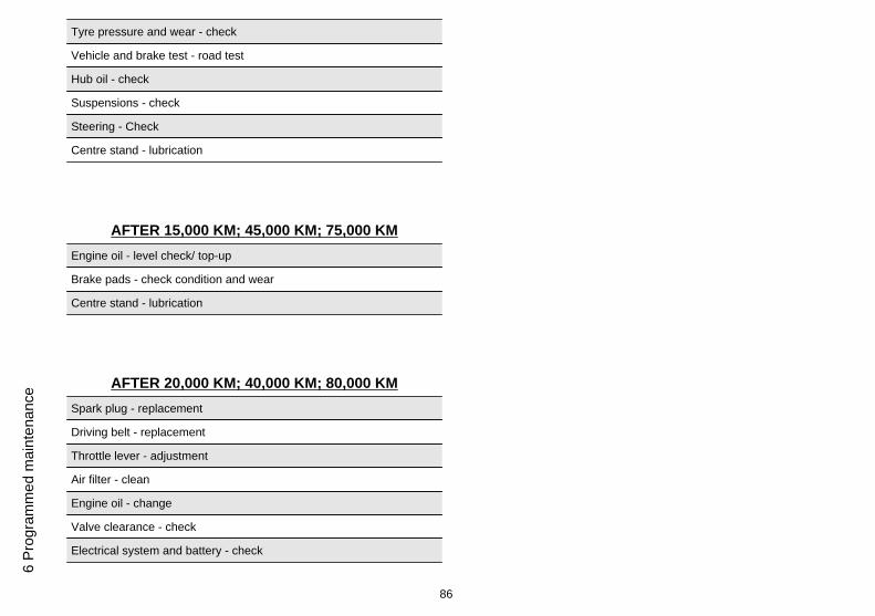
Tyre pressure and wear - check
Vehicle and brake test - road test
Hub oil - check
Suspensions - check
Steering - Check
Centre stand - lubrication
AFTER 15,000 KM; 45,000 KM; 75,000 KMEngine oil - level check/ top-up
Brake pads - check condition and wear
Centre stand - lubrication
AFTER 20,000 KM; 40,000 KM; 80,000 KMSpark plug - replacement
Driving belt - replacement
Throttle lever - adjustment
Air filter - clean
Engine oil - change
Valve clearance - check
Electrical system and battery - check
86
6 Pr
ogra
mm
ed m
aint
enan
ce
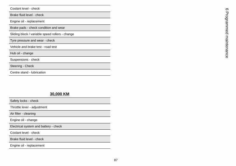
Coolant level - check
Brake fluid level - check
Engine oil - replacement
Brake pads - check condition and wear
Sliding block / variable speed rollers - change
Tyre pressure and wear - check
Vehicle and brake test - road test
Hub oil - change
Suspensions - check
Steering - Check
Centre stand - lubrication
30,000 KMSafety locks - check
Throttle lever - adjustment
Air filter - cleaning
Engine oil - change
Electrical system and battery - check
Coolant level - check
Brake fluid level - check
Engine oil - replacement
87
6 Programm
ed maintenance
Hub oil - check
Brake pads - check condition and wear
Sliding block / variable speed rollers - change
Tyre pressure and wear - check
Vehicle and brake test - road test
Suspensions - check
Steering - Check
Centre stand - lubrication
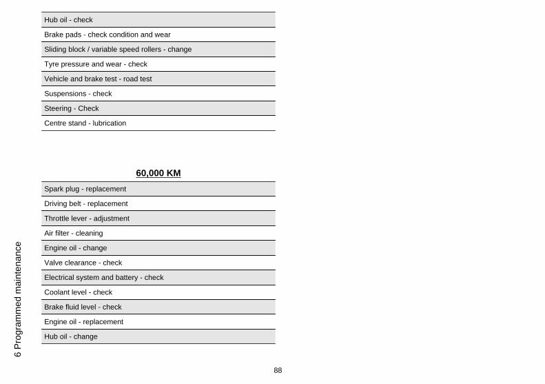
60,000 KMSpark plug - replacement
Driving belt - replacement
Throttle lever - adjustment
Air filter - cleaning
Engine oil - change
Valve clearance - check
Electrical system and battery - check
Coolant level - check
Brake fluid level - check
Engine oil - replacement
Hub oil - change
88
6 Pr
ogra
mm
ed m
aint
enan
ce
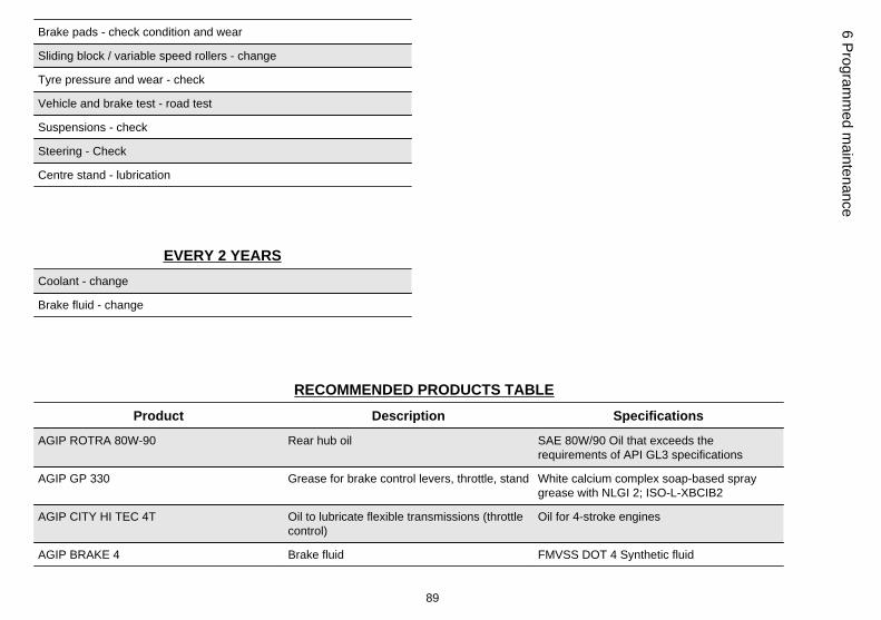
Brake pads - check condition and wear
Sliding block / variable speed rollers - change
Tyre pressure and wear - check
Vehicle and brake test - road test
Suspensions - check
Steering - Check
Centre stand - lubrication
EVERY 2 YEARSCoolant - change
Brake fluid - change
RECOMMENDED PRODUCTS TABLEProduct Description Specifications
AGIP ROTRA 80W-90 Rear hub oil SAE 80W/90 Oil that exceeds therequirements of API GL3 specifications
AGIP GP 330 Grease for brake control levers, throttle, stand White calcium complex soap-based spraygrease with NLGI 2; ISO-L-XBCIB2
AGIP CITY HI TEC 4T Oil to lubricate flexible transmissions (throttlecontrol)
Oil for 4-stroke engines
AGIP BRAKE 4 Brake fluid FMVSS DOT 4 Synthetic fluid
89
6 Programm
ed maintenance

Product Description Specifications
AGIP PERMANENT SPEZIAL coolant Monoethylene glycol-based antifreeze fluid,CUNA NC 956-16
AGIP FILTER OIL Oil for air filter sponge Mineral oil with specific additives for increasedadhesiveness
AUTOSOL METAL POLISH Muffler cleaning paste Specific product for cleaning and polishingstainless steel mufflers.
AGIP CITY HI TEC 4T Engine oil SAE 5W-40, API SL, ACEA A3, JASO MASynthetic oil
AGIP GREASE SM 2 Grease for the tone wheel revolving ring Soap-based lithium grease containing NLGI 2Molybdenum disulphide; ISO-L-XBCHB2, DINKF2K-20
AGIP GREASE PV2 Grease for the steering bearings, pin seats andswinging arm
White anhydrous-calcium based grease toprotect roller bearings; temperature rangebetween -20 C and +120 C; NLGI 2; ISO-L-XBCIB2.
90
6 Pr
ogra
mm
ed m
aint
enan
ce

TABLE OF CONTENTS
AAir filter: 47, 48
BBattery: 52, 53Brake: 50, 66
DDisc brake: 66
EEngine oil: 40, 41Engine stop: 15
FFuel: 20Fuses: 54
HHeadlight: 60Horn: 13Hub oil: 43
IIdentification: 23Immobilizer: 15, 18Instrument panel: 11
KKey switch: 11Keys: 16
LLight switch: 14
MMaintenance: 39, 83, 84
Mirrors: 65
SSaddle: 21, 23Scheduled maintenance: 84Shock absorbers: 31Spark plug: 46Stand: 35Start-up: 14
TTank: 20Technical Data: 73Top box: 24Transmission: 36Tyre pressure: 30Tyres: 45
91

The descriptions and illustrations given in this publication are not binding. While the basic specifications as described and illustrated in this manualremain unchanged, PIAGGIO-GILERA reserves the right, at any time and without being required to update this publication beforehand, to make anychanges to components, parts or accessories, which it considers necessary to improve the product or which are required for manufacturing or con-struction reasons.
Not all versions/models shown in this publication are available in all countries. The availability of single versions should be checked at the official Piaggio sales network.
"© Copyright 2007 - PIAGGIO & C. S.p.A. Pontedera. All rights reserved. Reproduction of this publication in whole or in part is prohibited."
PIAGGIO & C. S.p.A. - After-Sales
V.le Rinaldo Piaggio, 23 - 56025 PONTEDERA (Pi)


