1
Philadelphia University
Faculty of Engineering Mechanical Engineering Department
Done by:-
2017
Basics of Engineering Drawing Manual
Eng. Laith R.I. Batarseh
Eng. Hanan Khamis

2
Table of contents SUBJECT
CHAPTER ONE: INTRODUCTION
Section 1.1: Introduction
Section 1.2: Drawing Instruments
Section 1.3: Line types
Section 1.4: lettering and numeral
Section 1.5: Block title
Section 1.6: Zoning
Section 1.7: Scale
Section 1.8: Positioning the drawing paper
Chapter One problems
CHAPTER TWO: GEOMETRIC TECHNIQUES
Section 2.1: Sketching
2.1.1:sketching types
2.1.2: sketching rules
Section 2.2: Line techniques
2.2.1: straight lines
2.2.2 Parallel lines ( triangles sliding method )
2.2.3: circles and arcs
2.2.4: irregular curves
Section 2.3: Geometric Construction
2.3.1: point, line, plane, solid and angels
2.3.2 Polygons and 3D elements
2.3.3 geometric operations
2.3.4 tangency
Section 2.4: Ellipse
2.4.1 Pin and string method
2.4.2 Concentric circle method
Chapter two problems
CHAPTER THREE: PROJECTION
Section 3.1 introduction
Section 3.2 multi – view drawing
3.2.1 Views of a solid
3.2.2 revolving of object and regular views
3.2.3 Necessary views

3
3.2.4 Two and one views
3.2.5 Hidden and center lines
3.2.6 Alignment of the views
3.2.7 Priorities of the drawing lines in multi – view
drawing
Section 3.3: Orthogonal projections
3.3.1 Introduction
3.3.2 The glass box method
3.3.3 Surfaces, edges and corners in orthographic
projection
3.3.4 Adjacent areas and similar shapes of a surface
3.3.5 45o line ( miter line )
3.3.6 orthographic projection techniques
3.3.7 projection of basic objects
3.3.8 Alternative position of views
3.3.9 partial views
Section 3.4: First and third angle views
3.4.1 First angle projection
3.4.2 third angle projection
Section 3.5: sectioning
3.5.1 objective
3.5.2 lines in sectioning
3.5.3 Sectioning techniques
3.5.4 Section types
CHAPTER FOUR : DIMENSIONING
Section 4.1: Introduction
section 4.2: dimensioning rules
Section 4.3: common dimensioning types and cases
4.3.1 dimensioning a feature not drawn to scale
4.3.2 chain dimensioning and auxiliary dimensioning
4.3.3 parallel dimensioning
4.3.4 Running dimensioning
4.3.5 Dimensioning a circle
4.3.6 arc dimensioning
4.3.6 Angular dimensioning
Chapter three and four problems

4
CHAPTER FIVE : PICTORIAL DRAWINGS
section 5.1: oblique drawings
Section 5.2: isometric drawings
5.2.1 producing isometric drawings
5.2.2 drawing isometric circles
Section 5.3 Orthographic to isometric drawings: 5.4 problems
5
CHAPTER ONE
INTRODUCTION
Section 1.1: Introduction
Section 1.2: Drawing Instruments
Section 1.3: Line types
Section 1.4: lettering and numeral
Section 1.5: Block title
Section 1.6: Zoning
Section 1.7: Scale
Section 1.8: Positioning the drawing paper
Chapter One problems
6
CHAPTER ONE: INTRODUCTION
Section 1.1: Introduction
Engineering drawing is a universal language between engineers of certain bases and tools. To
have a perfect commutation between designers and the execution, a common language must
be used which the engineering is drawing. In other word, if you design and machinery and
you want to produce it, you need to draw it on a paper with its all specifications (ie. Material,
dimensions …, etc ) and give it to a technician or other engineer (eg. Industrial engineer)
and he/she will bring it to the reality.
Our objectives in engineering drawing is to express the bodies ( solids ) of height, width and
depth on a two dimensional surface ( paper )
Section 1.2: Drawing Instruments
There are many instruments that been used in engineering drawing and each one has its
own function and categories. So, when all these instruments are used in their correct position,
an objective drawing is produces. Most common engineering drawing instruments are:
1- Drawing media
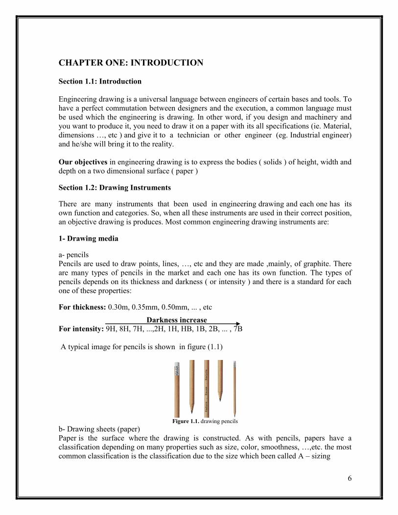
a- pencils
Pencils are used to draw points, lines, …, etc and they are made ,mainly, of graphite. There
are many types of pencils in the market and each one has its own function. The types of
pencils depends on its thickness and darkness ( or intensity ) and there is a standard for each
one of these properties:
For thickness: 0.30m, 0.35mm, 0.50mm, ... , etc
Darkness increase
For intensity: 9H, 8H, 7H, ...,2H, 1H, HB, 1B, 2B, ... , 7B
A typical image for pencils is shown in figure (1.1)
Figure 1.1. drawing pencils
b- Drawing sheets (paper)
Paper is the surface where the drawing is constructed. As with pencils, papers have a
classification depending on many properties such as size, color, smoothness, …,etc. the most
common classification is the classification due to the size which been called A – sizing
7
A – Sizing
A0 = 2A1, A1 = 2A2, A2 = 2A3, A3 = 2A4 , A4 = 2A5, A5 = 2A6
In this sizing, the width equals 2 of height. 2- Drawing equipment
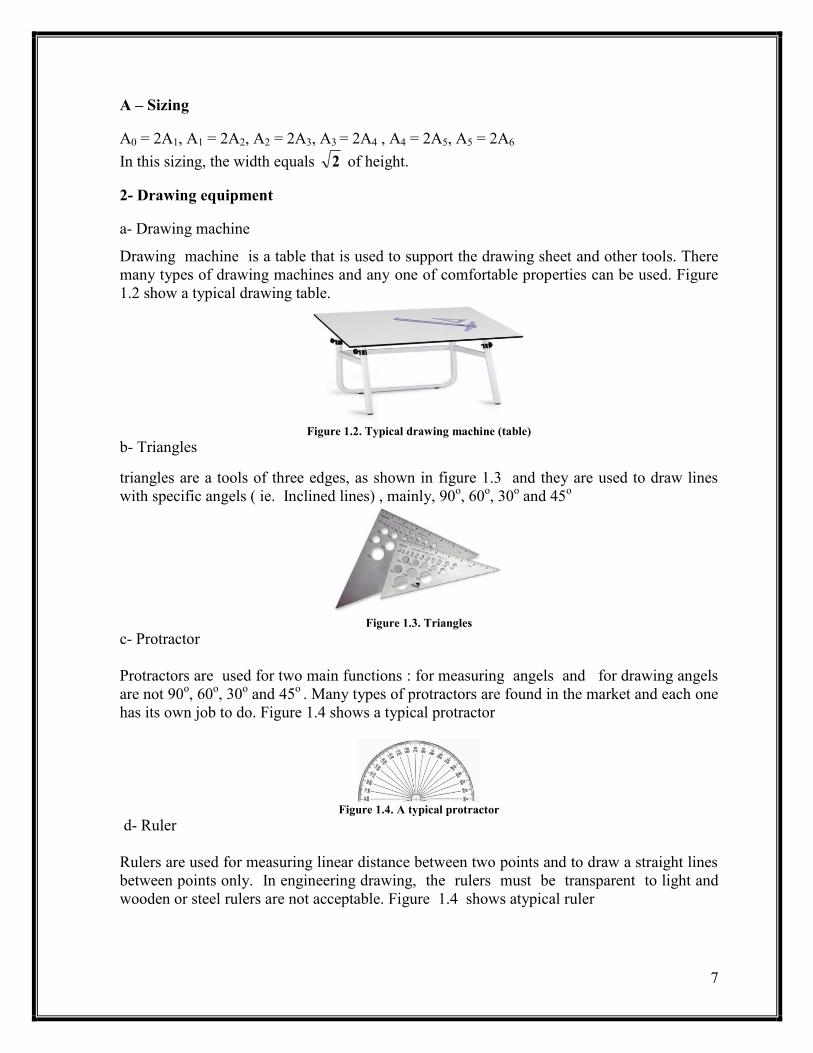
a- Drawing machine
Drawing machine is a table that is used to support the drawing sheet and other tools. There
many types of drawing machines and any one of comfortable properties can be used. Figure
1.2 show a typical drawing table.
Figure 1.2. Typical drawing machine (table)
b- Triangles
triangles are a tools of three edges, as shown in figure 1.3 and they are used to draw lines
with specific angels ( ie. Inclined lines) , mainly, 90o, 60
o, 30
o and 45
o
Figure 1.3. Triangles
c- Protractor
Protractors are used for two main functions : for measuring angels and for drawing angels
are not 90o, 60
o, 30
o and 45
o . Many types of protractors are found in the market and each one
has its own job to do. Figure 1.4 shows a typical protractor
Figure 1.4. A typical protractor
d- Ruler
Rulers are used for measuring linear distance between two points and to draw a straight lines
between points only. In engineering drawing, the rulers must be transparent to light and
wooden or steel rulers are not acceptable. Figure 1.4 shows atypical ruler

8
Figure 1.5. A typical ruler
e- Scale
Scale is used as a ruler just for measuring. The scale has many faces and each face has a
particular scale that the drawer can use when he/she perform a scaling to his/her drawing.
The scaling will be discussed in the next chapter. Figure (1.6) shows a typical scale.
Figure 1.6. a typical scale
f- Compass
Compasses are used to draw arcs and circles (arc is a part of a circle) that have a certain
center and a certain radius and there is another type for measurement purposes .There are
many types in market. However, our interest is in the measuring and drawing compasses.
For drawing: open the compass to the desired radius and then put the needle on the center of
arc or circle and revolve the compass to have your arc.
For measuring: open the two needle compass so each needle lies on one point and then take
the measurement from a ruler or scale
Note: - taking the measurement from a compass is more accurate than the ruler or scale
A typical compass is shown in figure 1.7
Figure. 1.7 A typical compass
g- Eraser
Eraser is used to erase any incorrect lines. Many types of erasers are found in the market.
However, you must choose a one that does not leave dirt
h- Brushes
Brushes are used to remove the dust and dirt and the waste of using eraser over the drawing

9
i- Irregular curves (French curves)
These curves are used to draw an irregular curves and it comes in many shapes and sizes . To
use these curves , you need to have points that lie on a certain curve then by trial and error
you chose the suitable curve to connect these points. A typical French curves are shown in
figure 1.8.
Figure.1.8 a typical French curve
j- T – Square
T – Square is used with the drawing table to draw a horizontal lines and to do that you must
first fix your paper on the drawing table where one line in the paper with the edge of the T –
Square. Now any line you draw by moving T – Square up and down and drawing by using
the same edge is parallel to your reference line. A typical T – Square is shown in figure 1.9
Figure.1.9 a typical T – Square
h- Circles template
it is used to draw the small circles. A typical circles template is shown in figure 1.10
Figure 1.10. a typical circles template
Section 1.3 line types
Each drawing consists of liens and so the acceptance quality of the drawing depends on the
lines been used which depends on two main line properties: intensity and size. In fact, in
engineering drawing many types of lines are used and each one has its own specifications
and function . Table 1.1 shows the most common used lines in engineering drawing.

11
Table 1.1:- line types: name, specifications and function
Function Specifications Name
For outlines or visible lines of
an object
Continues 0.7mm HB
Object line
( visible line )
Are used when there is a
symmetry ( ie. When you can
divide the drawing into two
identical parts )
Compost of long and short dashes
alternately and evenly spaced
Drawn by 0.3 2H
Center line
Are used to draw the hidden
features (ie. Invisible lines )
0.3 mm of short dashes evenly spaced
Hidden line
Function Specifications Name
To describe a part dimension
(will be discussed later in the
dimensioning chapter )
Shall terminate in arrowheads at each
end
Dimension line
It can be zigzag when the dimension is
too long
To indicate a point or portion
to which a number, note or
other reference applies
0.5 mm HB
Leader line
Used to break the long parts
so it can be drawn on a
regular sheets
Straight zigzagging line
0.3 mm HB
Break line
( long )
Used to indicate the
alternative position of a part
of the item delineated or
repeated details
0.3 mm HB
Phantom lines
Used to indicate the exposed
surfaces of an object in a
sectional view
0.3 mm 2H
Section line
Used to indicate the position
of datum plane
0.5 mm HB
Datum line

11
Used to indicate a plane or
planes in which a section is
taken
0.7 or 0.5 mm HB
Cutting plane
Used to indicate the plane or
planes for which a surface or
surfaces are viewed
0.7 or 0.5 mm HB
Viewing plane
Used when there is an
insignificant part is not
shown
Free hand sketch
Break line
( short )
Used to help the drawer in
drawing process Construction line
Figure 1.11 shows a typical use for these types
Figure 1.11. Line convention
Standards for drawing lines:-
In engineering drawing, there are some standards and regulations for drawing the correct line
and for each type of line, there are some constrained that must be respected. The most
common constrained or rules are:-
Center lines must cross without voids
Dimension lines must terminate in arrowhead at each end and must be unbroken except
when space is required for the dimension
The leader lines must be unbroken and terminating in any shape of arrowhead, dot or
wavy line
For long break line, the zigzagging lines can be done by hand
Sectioning lines must indicates the material of the object
The hidden lines must start and end by a dash

12
Section 1.4 lettering and numeral
Any drawing will contain some text either letters and/or numbers. In engineering drawing,
there are standard for drawing letters and numbers and the most common standards are:-
1- All lettering shall be in capital letters
2- All numbers shall be Arabic
3- Allows draw from up to down and from left to right for person who uses his/her right hand
in drawing and from right to left for the person who uses the left hand in drawing
4- The letters style is, usually, Roman
5- All letters must be drawn horizontally ( ie. No rotated letters or numerals )
6- The height of letters is specified by the size of drawing
7- The lettering must be drawn between two guide lines ( 0.3 mm 2H parallel and horizontal
lines of the letter height )
Figure 1.12 shows how to draw the lettering and numerical in engineering drawing
Figure 1.12. the standard way for lettering and numerals
Section 1.5 block title
Any drawing must have a specific frame and block title. A one of the most used frame and
title block is shown in figure 1.13.
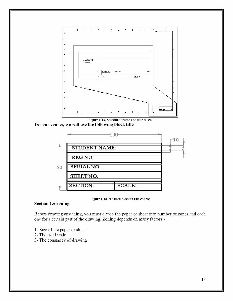
13
Figure 1.13. Standard frame and title block
For our course, we will use the following block title
Figure 1.14. the used block in this course
Section 1.6 zoning
Before drawing any thing, you must divide the paper or sheet into number of zones and each
one for a certain part of the drawing. Zoning depends on many factors:-
1- Size of the paper or sheet
2- The used scale
3- The constancy of drawing

14
Section 1.7 scaling
In many cases , the designer need to minimize his/her drawing if the real parts are too large
( eg. Buildings ) or to magnify it if it is too small (eg. Micro - tools ) . in both cases the
designer needs to use scale. However, the drawing must be made to full scale as possible as
could and the dimensions must be as drawing in the paper ( magnified or minimized ).
In some cases ( like the instruction drawings ), the dimensions are drawn with the real values
and that is only to simplify the process. There are many constrained in using scaling and they
are:
1- the preferred scales are:-
a- reducing: 1/2, 1/4 , 1/10 , 1/20
b- enlarging: 2/1, 4/1, 10/1 , 20/14
2- some certain drawings cannot be drawn with scaling such as wiring and schematic
diagrams drawings
3- the scale must be mentioned in the title block
4- for computer drawing, its preferred to use the full scale
Section 1.8 positioning the drawing paper
In engineering drawing, the paper is positioned ( ie. Fixed ) on the drawing machine by a
standard way to have the most comfortable conditions for the drawer and to reduce the effort
and time in drawing horizontal , vertical and inclined straight or curved lines. The standard
way to position your drawing is :
1- chose a line in the drawing, frame or the paper edge as a reference line
2- put the large edge of the T – Square on this line and the small edge on the table left edge
3- fix your paper using a tap

15
Problem 1.1 :- draw the following lettering inside the given guide lines
Problem 1.2:- draw the following numeral inside the given guide lines
Chapter One Problems
16
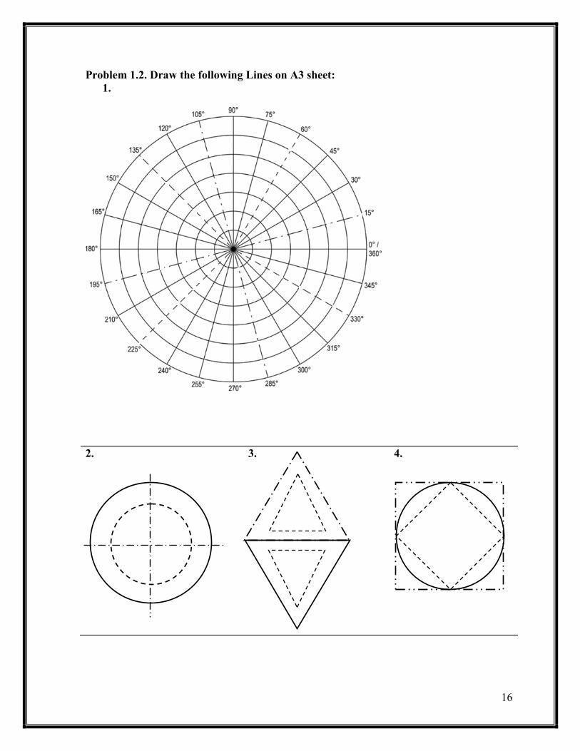
Problem 1.2. Draw the following Lines on A3 sheet:
1.
2.
3. 4.

17
5.
6.
7. 8.
18
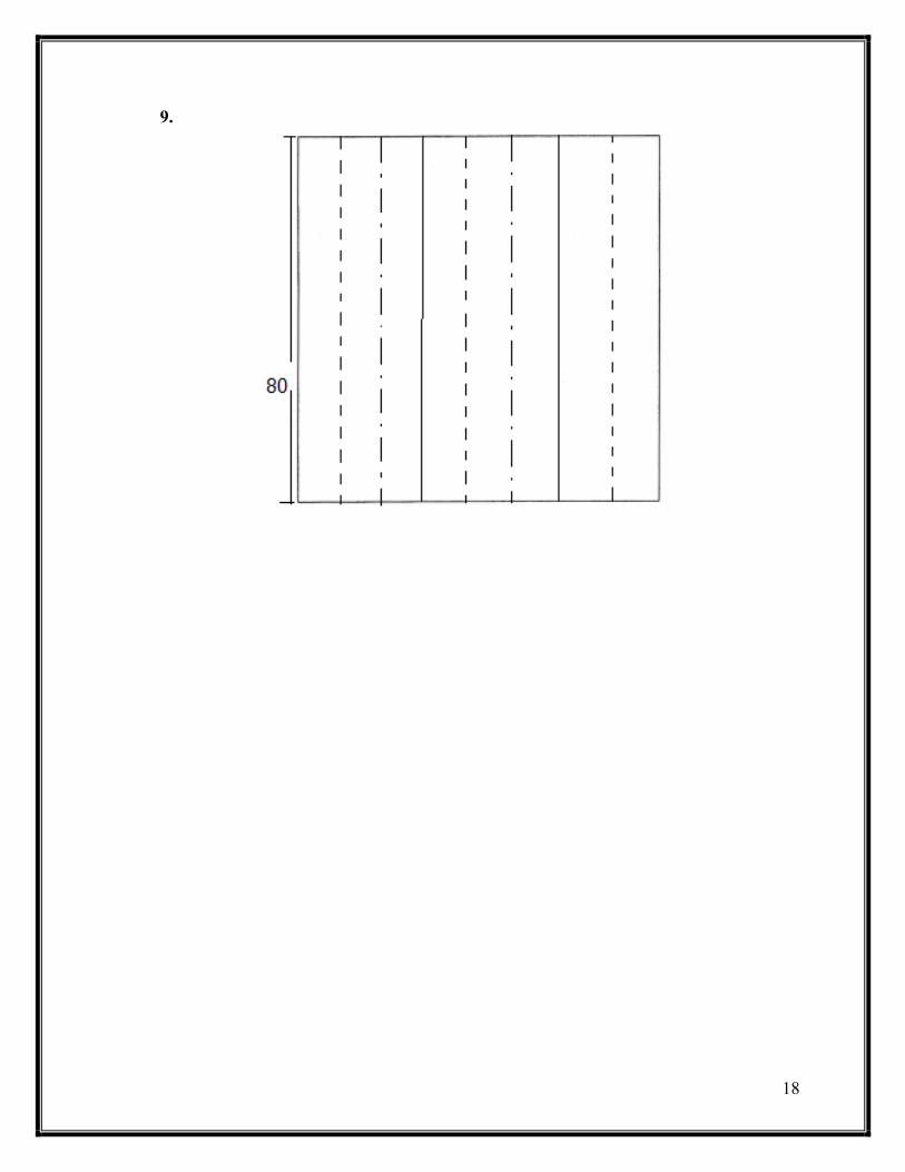
9.

19
CHAPTER TWO
GEOMETRIC TECHNIQUES Section 2.1: Sketching
2.1.1:sketching types
2.1.2: sketching rules
Section 2.2: Line techniques
2.2.1: straight lines
2.2.2 Parallel lines ( triangles sliding method )
2.2.3: circles and arcs
2.2.4: irregular curves
Section 2.3: Geometric Construction
2.3.1: point, line, plane, solid and angels
2.3.2 Polygons and 3D elements
2.3.3 geometric operations
2.3.4 tangency
Section 2.4: Ellipse
2.4.1 Pin and string method
2.4.2 Concentric circle method
Chapter two problems

21
CHAPTER TWO: GEOMETRIC TECHNIQUES
Section 2.1 sketching
2.1.1 Sketching types
There are four types of sketching:
1- Orthographic sketching: in this sketching, the object is been described by its orthogonal
views as shown in figure 2.1. this method provide an accurate information for the manu-
facturing and detail design.
Figure 2.1. orthographic sketching
2- Pictorial sketching : this method is used more with freehand sketching. This method is
shown in figure 2.2
Figure 2.2. Pictorial sketching
3- Isometric sketching: in this method, receding lines are drawn at 30o and are usually kept
at true measured lengths as shown in figure 2.3

21
Figure 2.3. isometric sketching
4- Oblique sketching: in this method, the front face is sketched as a truth shape and the third
axis is drawn at 45o,30o or 60o and the length is reduced to 50% as shown in figure 2.4.
sometimes, this sketching is called ‘ cabinet sketching’.
Figure 2.4. oblique sketching
2 .1.2 sketching rules
In sketching or even drawing, there are some rules must be followed to have a patter drawing
and comfortable conditions. These rules are too much due to the comfortability of human but
we can summarize them by :-
1. Use different pencils with different intensity rather than applying a pressure on pencil to
have multi intensities which cause tension in hand
2. Allows draw with inclined pencil
3. When you sketch, you must see what you are sketching
4. Rotate the pencil as you draw to have a constant thickness of line
5. Draw the horizontal lines from left to right if you use your right hand in drawing and
from left to right if you use the left hand (ie. Allows drag the pencil on the sheet )
6. Draw the vertical lines from up to down
7. When you draw an inclined line, drag the pencil never push it
8. Don’t make your drawing dirty
Section 2.2 Line techniques
As said before, any drawing consists of lines and lines are either straight (horizontal, vertical
and inclined) or curved (circular, elliptical, …, etc. ). There are many techniques based on
22
mathematics and geometric theories are used to draw both types of lines and these techniques
distinguish the engineering drawing from other drawings.
2.1.1 Straight lines
Straight line is the shortest distance between two points in the space and so to draw straight
line you must identify two points. There are special cases for drawing a straight line easily
and these cases are:-
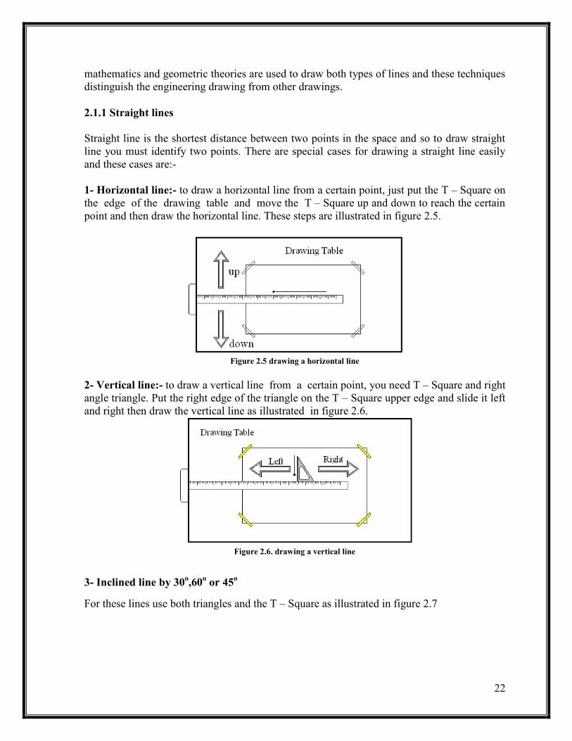
1- Horizontal line:- to draw a horizontal line from a certain point, just put the T – Square on
the edge of the drawing table and move the T – Square up and down to reach the certain
point and then draw the horizontal line. These steps are illustrated in figure 2.5.
Figure 2.5 drawing a horizontal line
2- Vertical line:- to draw a vertical line from a certain point, you need T – Square and right
angle triangle. Put the right edge of the triangle on the T – Square upper edge and slide it left
and right then draw the vertical line as illustrated in figure 2.6.
Figure 2.6. drawing a vertical line
3- Inclined line by 30o,60
o or 45
o
For these lines use both triangles and the T – Square as illustrated in figure 2.7

23
Figure 2.7. drawing an inclined line by 30o,60o or 45o
For other cases of straight lines you need only to locate the positions of the two drawing
points and draw the line from one point to the other using a ruler
2.2.2 Parallel lines (triangles sliding method)
As in other techniques, drawing parallel lines are done by using the engineering drawing
instruments. In engineering drawing and to draw a parallel line to other certain line, the
sliding of triangles is used. Triangles sliding method depends on the triangle similarities.
This method is described in figure 2.8
Figure 2.8 triangles sliding method
2.2.3 Circles and arcs
Circles are a curvilinear line and if a point moves along it will have a constant distance
(radius) from other point called ‘center’. In other word, to draw a circle you need to locate
the center position and the radius of that circle.
In general, you can use the compass to draw a circle by opining the compass to the radius of
the circle and strike the compass needle on the center of the circle. Finally, swing the
compass clock-wise and counter clock-wise to draw the circle.
Note: - the arc is a part of a circle
2.2.4 Irregular curves
When an irregular curves are drawn, a set of points are drawn first and then by using the
irregular curves ( French curves ) and trial and error in choosing the suitable curve, you can
draw the suitable curve.

24
Section 2.3 geometric construction
2.3.1 Point, line, plane, body and angels
Point is a dimensionless feature or a circle of radius zero and it can be represented by a
cross of two lines
Line is the path drawn by the movement of a point in the space. Parallel lines have a
constant distance between each other. Perpendicular lines are lines that have 90o angel
between each other
Plane is the effect of line movement and it could be a surface
Body is the effect of plane movement and it is touchable (i.e. Real objects (solids ) )
Angel is the radial measurements between two intersecting lines and there are four types
of angels and they are illustrated in figure 2.9
Figure 2.9. angel types
# Complementary and supplementary angels:- Two angels can be complementary if their
summation is 90o and supplementary if their summation is 180
o
2.3.2 Polygons and 3D elements
2.3.2.1 Polygons
Polygon is a plane bounded by straight three or more lines. Table 2.1 summarize the most
famous polygons.
Table 2.1:- polygons types: name, number of sides and types
Types Name
Number of sides
Triangle
( 3 )
Types Name
Number of sides

25
Quadrilaterals
(4)
a- five(pentagon)
b-six(hexagon)
c- seven(heptagon)
d- eighth(octagon)
Note:- the regular polygon can be inscribed in or circumscribed around a circle
2.3.2.2 three dimensional elements
Most of three dimensional elements or objects are consists of bounded surfaces which called
faces and these elements are called polyhedron. Polyhedral has many types and shapes. Table
(2.2) shows the most common polyhedrons used in engineering applications.
Table 2.2:- three dimensional element types: name, shapes and types
Types Name
Prisms
Pyramids

26
Cylinder
Cones
Sphere
2.3.3 Geometric operations
2.3.3.1 Bisecting lines and angels
In many cases, you need to bisect a line or an angel into two equal parts or in other word
locate the center of a line or to have a half of an angel. These requirements can be done by
many methods.
# Bisecting or finding the center of a line
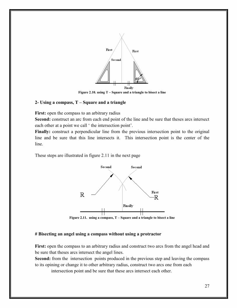
1- Using T – Square and a triangle
First: construct an inclined line of angel 30o,45
o or 60
o which is the angel of the used triangle
from each end of the line and be sure that this line intersect each other at some point
we call it ‘ the intersection point ’. This step will create an isoscale triangle where the
line is the base.
Second: from the intersection point, construct a perpendicular line to the original line (ie.
The base of the iso-scale triangle drawn in the previous step ) and be sure that this
line intersect the base.
Finally: the last intersection point produced from the previous step is the center of the
original line.
These steps are illustrated in figure 2.10
Note:- from now on, the phrase construct an arc or a line means to draw a construction arc or line with 0.3 or 0.5 mm 2H pencil
27
Figure 2.10. using T – Square and a triangle to bisect a line
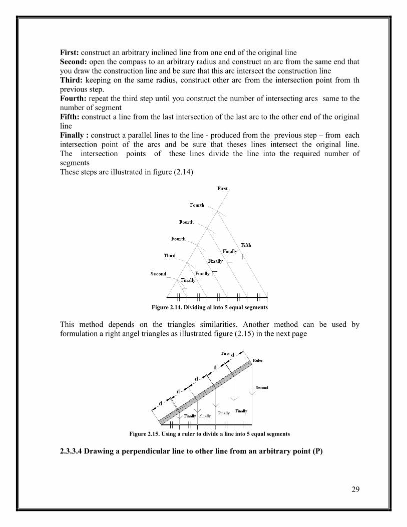
2- Using a compass, T – Square and a triangle
First: open the compass to an arbitrary radius
Second: construct an arc from each end point of the line and be sure that theses arcs intersect
each other at a point we call ‘ the intersection point’.
Finally: construct a perpendicular line from the previous intersection point to the original
line and be sure that this line intersects it. This intersection point is the center of the
line.
These steps are illustrated in figure 2.11 in the next page
Figure 2.11. using a compass, T – Square and a triangle to bisect a line
# Bisecting an angel using a compass without using a protractor
First: open the compass to an arbitrary radius and construct two arcs from the angel head and
be sure that theses arcs intersect the angel lines.
Second: from the intersection points produced in the previous step and leaving the compass
to its opining or change it to other arbitrary radius, construct two arcs one from each
intersection point and be sure that these arcs intersect each other.

28
Finally: from the last intersection point produced from the previous step, draw a line to the
angel head. This line is bisecting the angel.
Figure 2.12 illustrate these steps
Figure 2.12. using a compass to bisect an angel
2.3.3.2 Transforming an angel without using the protractor
To transform an angle from its original place to a new position, you need to have a compass
and a ruler.
First: construct an arbitrary arc from the angel head which intersect the angel lines.
Second: with the same radius, construct an arc from the head of the new angel and be sure
that this arc intersect the first line of the new angel
Third : open the compass to a radius equal to the distance between the two intersection
points produced from the first step and construct an arc from the intersection point
produced from the previous step and be sure that this arc intersect the first arc you
draw.
Finally: from the arcs intersection points, draw a line to the head of the new angle. This line
is the other line of the new angel.
Figure 2.13 illustrate these steps
Figure 2.13. transforming an angle with out using the protractor
2.3.3.3 Dividing a line into equal segments
To divide a line into equal parts without using the ruler by the traditional way which fails
when result of dividing the line length on the number of segment is not a correct number.
29
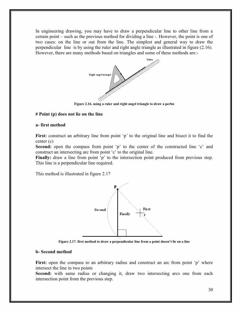
First: construct an arbitrary inclined line from one end of the original line
Second: open the compass to an arbitrary radius and construct an arc from the same end that
you draw the construction line and be sure that this arc intersect the construction line
Third: keeping on the same radius, construct other arc from the intersection point from th
previous step.
Fourth: repeat the third step until you construct the number of intersecting arcs same to the
number of segment
Fifth: construct a line from the last intersection of the last arc to the other end of the original
line
Finally : construct a parallel lines to the line - produced from the previous step – from each
intersection point of the arcs and be sure that theses lines intersect the original line.
The intersection points of these lines divide the line into the required number of
segments
These steps are illustrated in figure (2.14)
Figure 2.14. Dividing al into 5 equal segments
This method depends on the triangles similarities. Another method can be used by
formulation a right angel triangles as illustrated figure (2.15) in the next page
Figure 2.15. Using a ruler to divide a line into 5 equal segments
2.3.3.4 Drawing a perpendicular line to other line from an arbitrary point (P)
31
In engineering drawing, you may have to draw a perpendicular line to other line from a
certain point – such as the previous method for dividing a line -. However, the point is one of
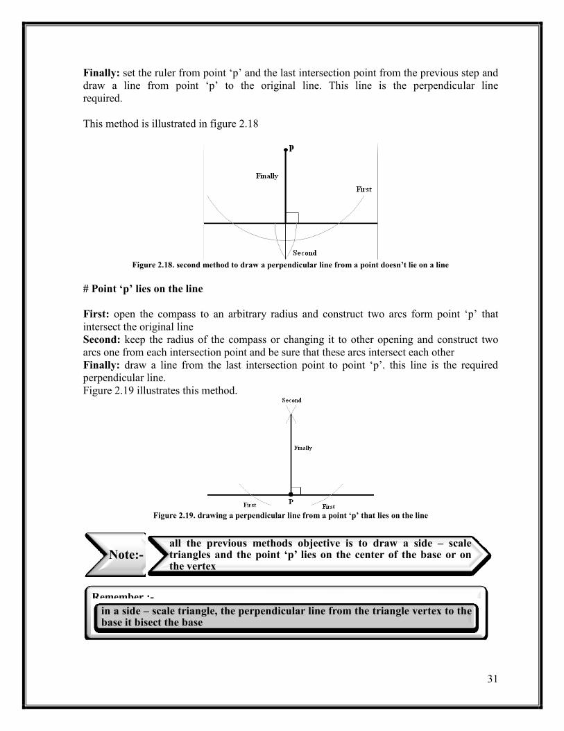
two cases: on the line or out from the line. The simplest and general way to draw the
perpendicular line is by using the ruler and right angle triangle as illustrated in figure (2.16).
However, there are many methods based on triangles and some of these methods are:-
Figure 2.16. using a ruler and right angel triangle to draw a perbn
# Point (p) does not lie on the line
a- first method
First: construct an arbitrary line from point ‘p’ to the original line and bisect it to find the
center (c)
Second: open the compass from point ‘p’ to the center of the constructed line ‘c’ and
construct an intersecting arc from point ‘c’ to the original line.
Finally: draw a line from point ‘p’ to the intersection point produced from previous step.
This line is a perpendicular line required.
This method is illustrated in figure 2.17
Figure 2.17. first method to draw a perpendicular line from a point doesn’t lie on a line
b- Second method
First: open the compass to an arbitrary radius and construct an arc from point ‘p’ where
intersect the line in two points
Second: with same radius or changing it, draw two intersecting arcs one from each
intersection point from the previous step.
31
Finally: set the ruler from point ‘p’ and the last intersection point from the previous step and
draw a line from point ‘p’ to the original line. This line is the perpendicular line
required.
This method is illustrated in figure 2.18
Figure 2.18. second method to draw a perpendicular line from a point doesn’t lie on a line
# Point ‘p’ lies on the line
First: open the compass to an arbitrary radius and construct two arcs form point ‘p’ that
intersect the original line
Second: keep the radius of the compass or changing it to other opening and construct two
arcs one from each intersection point and be sure that these arcs intersect each other
Finally: draw a line from the last intersection point to point ‘p’. this line is the required
perpendicular line.
Figure 2.19 illustrates this method.
Figure 2.19. drawing a perpendicular line from a point ‘p’ that lies on the line
Note:- all the previous methods objective is to draw a side – scale triangles and the point ‘p’ lies on the center of the base or on the vertex
Remember :-
in a side – scale triangle, the perpendicular line from the triangle vertex to the base it bisect the base
32
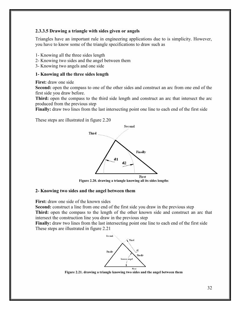
2.3.3.5 Drawing a triangle with sides given or angels
Triangles have an important rule in engineering applications due to is simplicity. However,
you have to know some of the triangle specifications to draw such as
1- Knowing all the three sides length
2- Knowing two sides and the angel between them
3- Knowing two angels and one side
1- Knowing all the three sides length
First: draw one side
Second: open the compass to one of the other sides and construct an arc from one end of the
first side you draw before.
Third: open the compass to the third side length and construct an arc that intersect the arc
produced from the previous step
Finally: draw two lines from the last intersecting point one line to each end of the first side
These steps are illustrated in figure 2.20
Figure 2.20. drawing a triangle knowing all its sides lengths
2- Knowing two sides and the angel between them
First: draw one side of the known sides
Second: construct a line from one end of the first side you draw in the previous step
Third: open the compass to the length of the other known side and construct an arc that
intersect the construction line you draw in the previous step
Finally: draw two lines from the last intersecting point one line to each end of the first side
These steps are illustrated in figure 2.21
Figure 2.21. drawing a triangle knowing two sides and the angel between them

33
3- Knowing two angels and one side
First: draw the known side
Second: construct two intersecting lines one from each end of the first side with one of the
known angels
Finally : draw two lines from the last intersecting point one line to each end of the first side
These steps are illustrated in figure 2.22
Figure 2.22. drawing a triangle knowing two angels and one side
Special case:- equilateral triangle
to specify an equilateral triangle by only its side because all the sides have the same length
and all its angels are 60o so you can draw this type of triangle by using only one of its sides.
2.3.4 Tangency
Tangency mean that two curves or lines touch each other by only one pint (ie. There is only
one common between the two curves) and there is no an intersection point. There are many
cases of tangency and we will try to cover the most common cases.
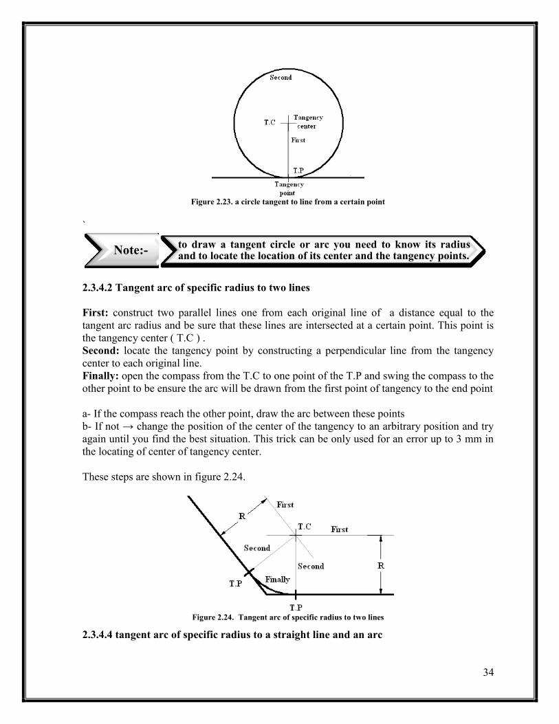
2.3.4.1 a circle tangent to line from a certain point
First: construct a perpendicular line of length equal to the radius of the circle from the point
of tangency.
Second: draw the circle where the center is the end of the perpendicular
This method is illustrated in figure 2.23
Note:- you can use a ruler instead of a compass
34
Figure 2.23. a circle tangent to line from a certain point
`
2.3.4.2 Tangent arc of specific radius to two lines
First: construct two parallel lines one from each original line of a distance equal to the
tangent arc radius and be sure that these lines are intersected at a certain point. This point is
the tangency center ( T.C ) .
Second: locate the tangency point by constructing a perpendicular line from the tangency
center to each original line.
Finally: open the compass from the T.C to one point of the T.P and swing the compass to the
other point to be ensure the arc will be drawn from the first point of tangency to the end point
a- If the compass reach the other point, draw the arc between these points
b- If not → change the position of the center of the tangency to an arbitrary position and try
again until you find the best situation. This trick can be only used for an error up to 3 mm in
the locating of center of tangency center.
These steps are shown in figure 2.24.
Figure 2.24. Tangent arc of specific radius to two lines
2.3.4.4 tangent arc of specific radius to a straight line and an arc
Note:- to draw a tangent circle or arc you need to know its radius and to locate the location of its center and the tangency points.

35
Case one : the tangent arc touch the arc from outside
First: construct a line from the straight line with a distance equal to the tangent arc radius
Second: open the compass to a radius equal to the original radius plus the tangent radius and
construct an intersecting arc to the constructed line from the center of the original
arc. The point of intersection in the tangency center
Third: from the T.C construct a perpendicular line to the original line and locate the first T.P
Fourth: construct a c – c line ( center – center line ) a the intersection point between this line
and the original arc is the second T.P
Finally: repeat the final step from the previous sub section ( 2.3.4.3 )
These steps are illustrated in figure 2.25
Figure 2.25. tangent arc of specific radius to a straight line and an arc
case one : the tangent arc touch the arc from outside
Case two: the tangent arc touch the arc from inside
First: repeat the first step from the previous case
Second: repeat the second step from the previous case but this time subtract the radius of the
tangent arc from the original arc radius.
Third: repeat the third step from the previous case
Fourth: repeat the fourth step from the previous case and extend the c – c line to intersect the
original arc to locate the second T.P
Finally: repeat the final step from the previous case
These steps are illustrated in figure 2.26 in the next page
Figure 2.26. tangent arc of specific radius to a straight line and an arc
case two : the tangent arc touch the arc from inside
36
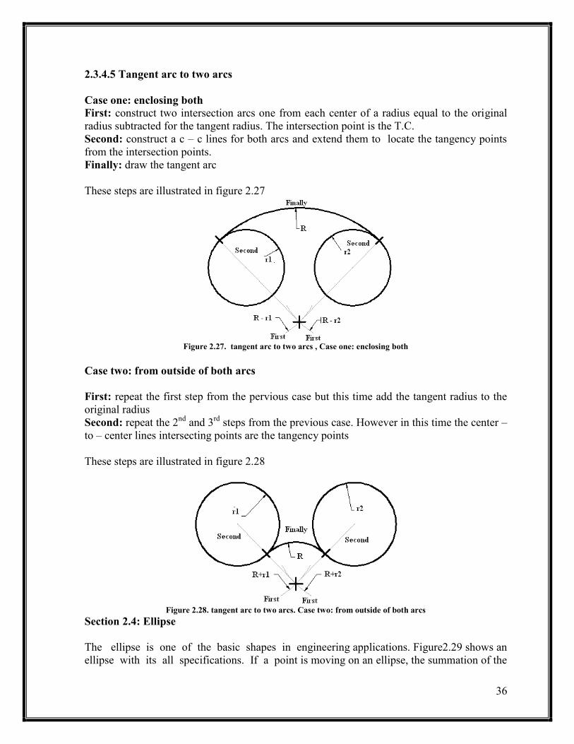
2.3.4.5 Tangent arc to two arcs
Case one: enclosing both
First: construct two intersection arcs one from each center of a radius equal to the original
radius subtracted for the tangent radius. The intersection point is the T.C.
Second: construct a c – c lines for both arcs and extend them to locate the tangency points
from the intersection points.
Finally: draw the tangent arc
These steps are illustrated in figure 2.27
Figure 2.27. tangent arc to two arcs , Case one: enclosing both
Case two: from outside of both arcs
First: repeat the first step from the pervious case but this time add the tangent radius to the
original radius
Second: repeat the 2nd
and 3rd
steps from the previous case. However in this time the center –
to – center lines intersecting points are the tangency points
These steps are illustrated in figure 2.28
Figure 2.28. tangent arc to two arcs. Case two: from outside of both arcs
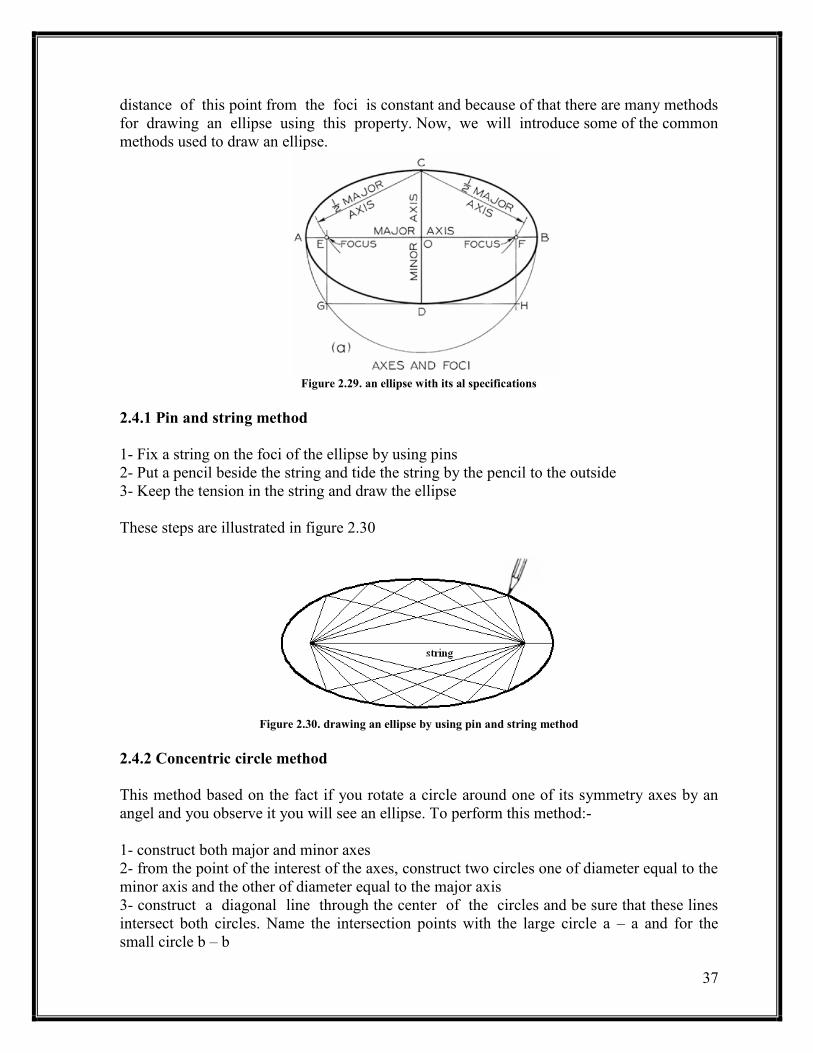
Section 2.4: Ellipse
The ellipse is one of the basic shapes in engineering applications. Figure2.29 shows an
ellipse with its all specifications. If a point is moving on an ellipse, the summation of the
37
distance of this point from the foci is constant and because of that there are many methods
for drawing an ellipse using this property. Now, we will introduce some of the common
methods used to draw an ellipse.
Figure 2.29. an ellipse with its al specifications
2.4.1 Pin and string method
1- Fix a string on the foci of the ellipse by using pins
2- Put a pencil beside the string and tide the string by the pencil to the outside
3- Keep the tension in the string and draw the ellipse
These steps are illustrated in figure 2.30
Figure 2.30. drawing an ellipse by using pin and string method
2.4.2 Concentric circle method
This method based on the fact if you rotate a circle around one of its symmetry axes by an
angel and you observe it you will see an ellipse. To perform this method:-
1- construct both major and minor axes
2- from the point of the interest of the axes, construct two circles one of diameter equal to the
minor axis and the other of diameter equal to the major axis
3- construct a diagonal line through the center of the circles and be sure that these lines
intersect both circles. Name the intersection points with the large circle a – a and for the
small circle b – b

38
4- From point a construct a parallel line to the minor axis and from the corresponding point b
construct a line parallel to the major axis and be sure that these two lines intersect each
other at some point. This intersection point is point in the expected ellipse
5- repeat steps 2 – 4 until you construct enough points to draw the ellipse and by using the
French curves you connect these points to draw the ellipse
These steps are illustrated in figure 2.31
Figure 2.31. drawing an ellipse by using concentric circle method
39
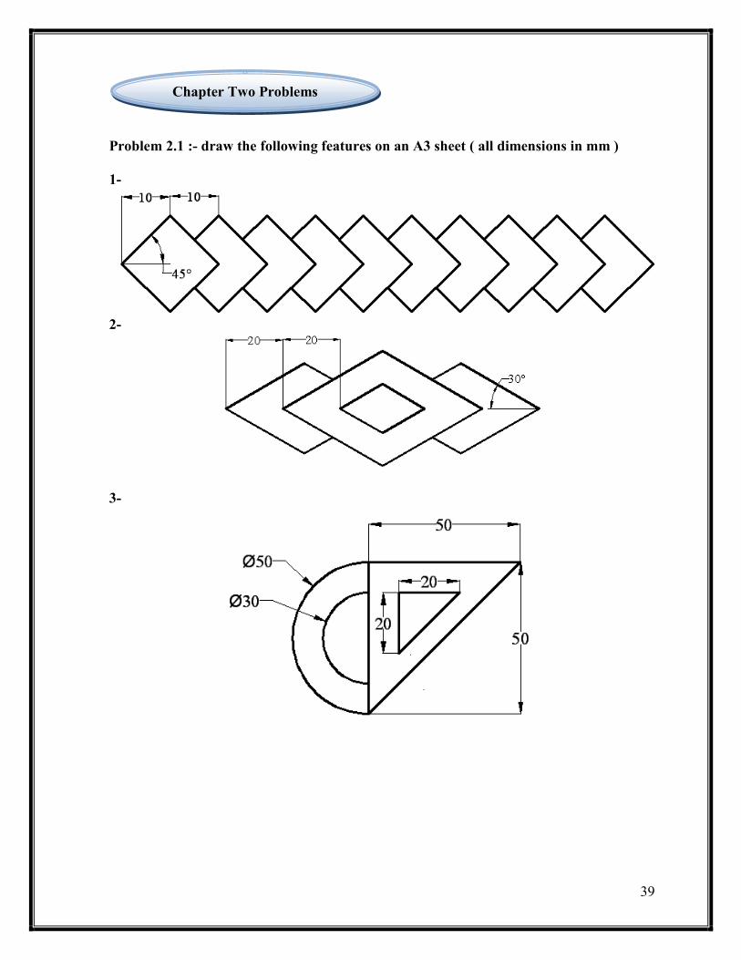
Problem 2.1 :- draw the following features on an A3 sheet ( all dimensions in mm )
1-
2-
3-
Chapter Two Problems

41
4-
5-
41
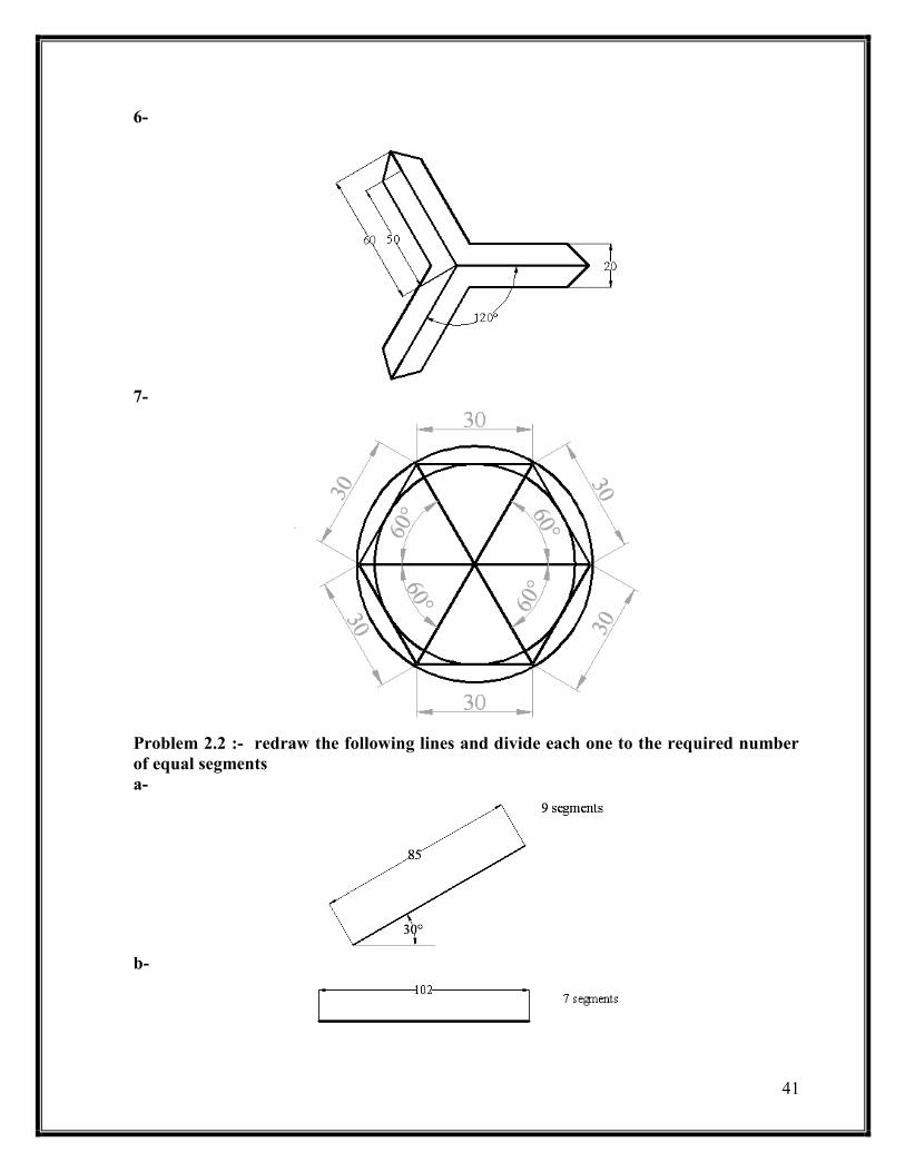
6-
7-
Problem 2.2 :- redraw the following lines and divide each one to the required number
of equal segments
a-
b-
42
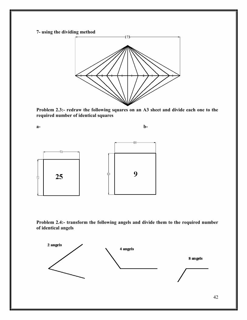
7- using the dividing method
Problem 2.3:- redraw the following squares on an A3 sheet and divide each one to the
required number of identical squares
a- b-
Problem 2.4:- transform the following angels and divide them to the required number
of identical angels
43
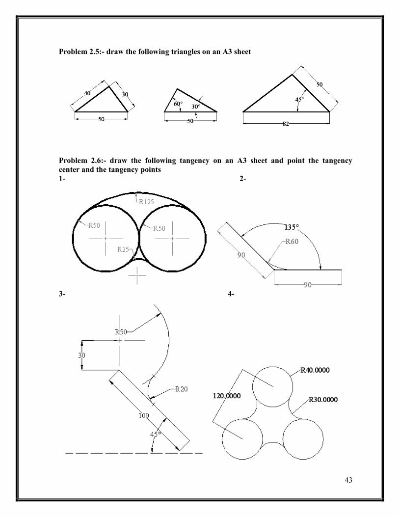
Problem 2.5:- draw the following triangles on an A3 sheet
Problem 2.6:- draw the following tangency on an A3 sheet and point the tangency
center and the tangency points
1- 2-
3- 4-

44
5-
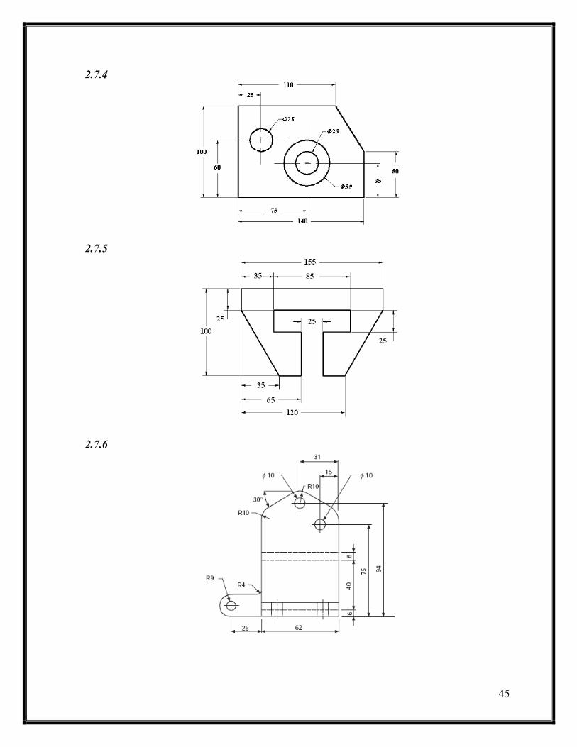
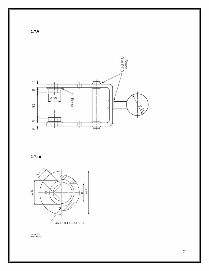
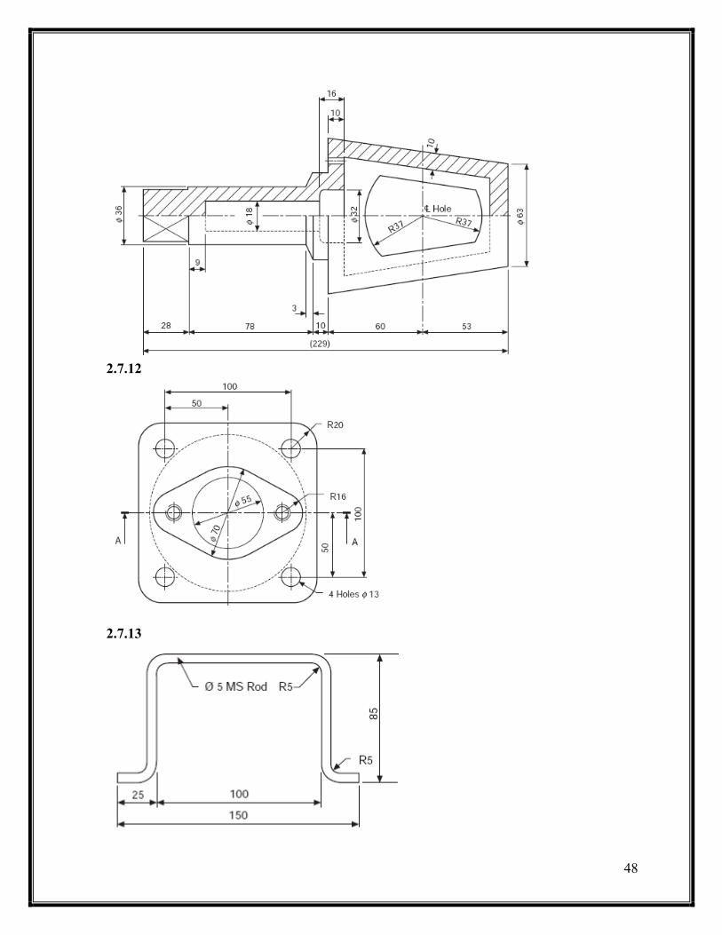
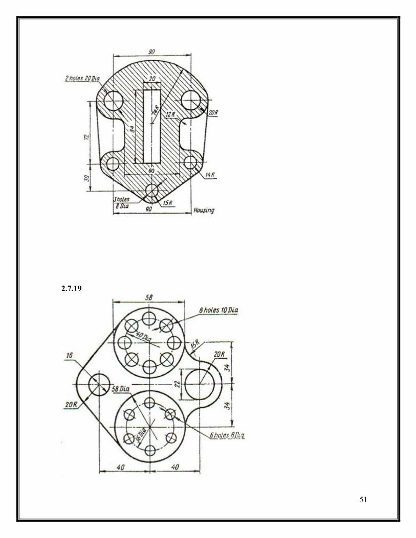
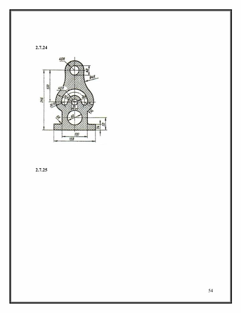
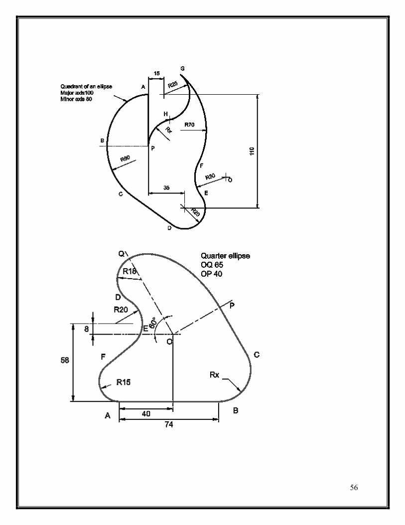
Problem 2.7:- draw the following features on an A3 sheet
2.7.1
2.7.2
2.7.3
45
2.7.4
2.7.5
2.7.6

46
2.7.7
2.7.8
47
2.7.9
2.7.10
2.7.11
48
2.7.12
2.7.13

49
2.7.14
2.7.15
2.7.16

51
2.7.17
2.7.18
51
2.7.19

52
2.7.20
2.7.21
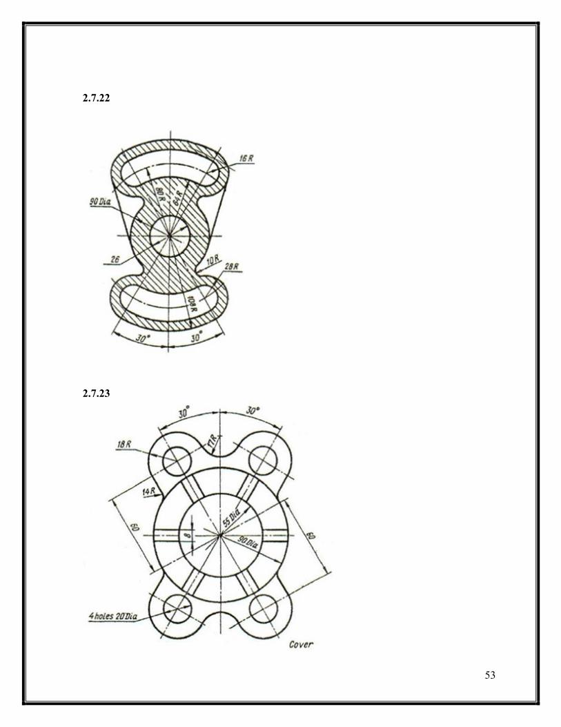
53
2.7.22
2.7.23
54
2.7.24
2.7.25
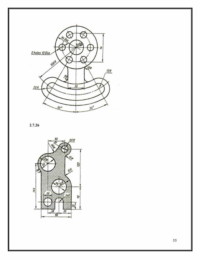
55
2.7.26
56


58
CHAPTER THREE
ORTHOGARPH PROJECTION
Section 3.1 introduction
Section 3.2 multi – view drawing
3.2.1 Views of a solid
3.2.2 revolving of object and regular views
3.2.3 Necessary views
3.2.4 Two and one views
3.2.5 Hidden and center lines
3.2.6 Alignment of the views
3.2.7 Priorities of the drawing lines in multi – view
drawing
Section 3.3: Orthogonal projections
3.3.1 Introduction
3.3.2 The glass box method
3.3.3 Surfaces, edges and corners in orthographic
projection
3.3.4 Adjacent areas and similar shapes of a surface
3.3.5 45o line ( miter line )
3.3.6 orthographic projection techniques
3.3.7 projection of basic objects
3.3.8 Alternative position of views
3.3.9 partial views
Section 3.4: First and third angle views
3.4.1 First angle projection
3.4.2 third angle projection
Section 3.5: sectioning
3.5.1 objective
3.5.2 lines in sectioning
3.5.3 Sectioning techniques
3.5.4 Section types

59
CHAPTER THREE: PROGECTION
Section 3.1: introduction
The most important objective of the engineering drawing is to transfer information between
the designer and the executer. All the designing processes end with a three dimensional
configuration in the designer mind which can be drawn in a piece of paper. However,
drawing the 3-D ( three dimensional ) object (ie. Solid ) will not give the full description for
the design and some details may be lost. In the 18th
century, a French mathematics and
engineer Gaspand Monge ( 1746 – 1818 ) , who was involved with the design of military
armory, developed using two planes of projections at right angel to each other a graphical
description for a solid and this system was called – and still – ‘ the descriptive geometry’.
Monge’s descriptive geometry set the basic for what now is known as the orthographic
projection.
Monge’s method is illustrated in figure 3.1.
Figure 3.1. Monge’s descriptive geometry
In this method, the 3-D solid is described by two perpendicular projection planes. In this
chapter, we will discus many rules and techniques for the orthographic projection
Section 3.2: multi – view drawing
3.2.1 Views of a solid
In previous chapter, we describe many methods which are used to sketch a 3-D solid such as
perspective, isometric, …, etc. Although these methods are used widely, they are not – in
some cases – enough for describing an engineering design due to the lake of dimensions or
non true dimensions or shapes.
So, for engineering prepuces , engineers transform their 3-D solid to many 2-D ( two
dimensional) drawings called ‘projections’ that fully describe the object or solid with all true
dimensions and shape. These drawings are called ‘views). Views for an object must be
arranged a system which is called ‘multi – view projection’. In this system, each view gives a
piece of information about the object. However, one view in most of times is not enough.
These views are front, rear, top, bottom, left and right. The concepts of these
61
Views will be discussed later.
There are many types of viewing and projection for this level, we will be enough with the
orthogonal projection due to its simplicity and popularly. For views: the front view is been
observed directly from the observer, the rear is the opposite view to the front view. The top
view is the up view of the object from the viewing side of the viewer, the bottom view is the
opposite view of the top view. The right and left views are the left and the right of object
respectively.
3.2.2 Revolving of object and regular views
You can obtain the front view by observing the object directly. However, the obtaining the
other views such as top, left, …, etc will be – some how – difficult due to the hidden features
in the solid. So, you are obligated to revolve the object to see or observe all the views you
need. The revolving process is constrained by a certain angel to be all views orthogonal
which is 90o so you revolve the object by 90
o over x,y or z axis to and made the view you
want as frontal view. In many cases, you cannot revolve the object because its either too
heavy or its still an idea in the designer mind so you are obligated to imagine the revolving
process which is in our course will be the most applicable way for projection.
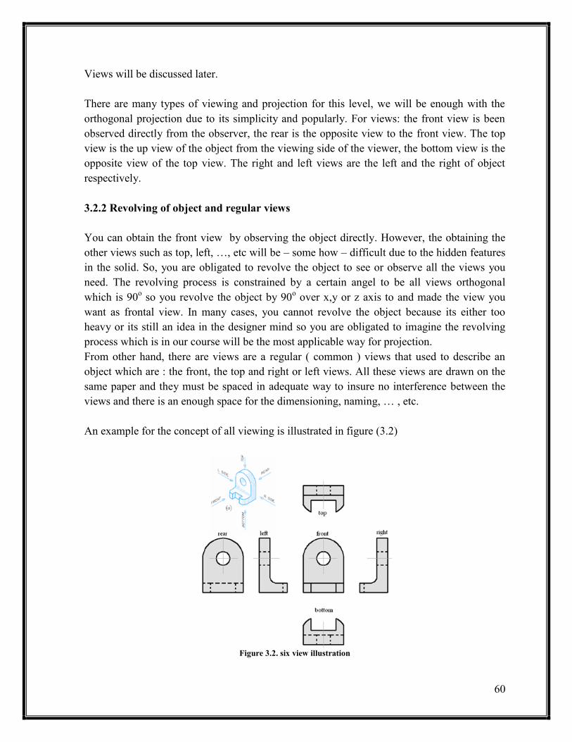
From other hand, there are views are a regular ( common ) views that used to describe an
object which are : the front, the top and right or left views. All these views are drawn on the
same paper and they must be spaced in adequate way to insure no interference between the
views and there is an enough space for the dimensioning, naming, … , etc.
An example for the concept of all viewing is illustrated in figure (3.2)
Figure 3.2. six view illustration
61
3.2.3 Necessary views
As said before, there are six views are used to describe a three dimensional object. However,
in many cases there are no need to draw all these views which reduce the effort and
confusing for engineering drawing reader. The choice of necessary views depends on many
parameters such as:-
1- Dimension: chose the most dimension view for the opposite views ( eg. Right and left
views )
2- Hidden lines: chose the less hidden lines view
3- Identical views: if there are two or more identical views, there is no need to draw all
views unless there is a need for display the dimensions
4- Fillets, corners, … , etc. ( ie. Details ): chose the most describing views which has the
most details
However, the most common views are the Top ( T ), Front ( F ) and Side ( L or R ) views
and for this level, these are the most common views that we will deal with
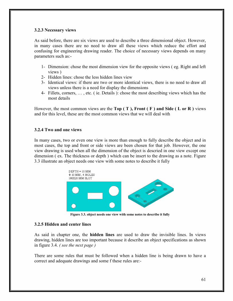
3.2.4 Two and one views
In many cases, two or even one view is more than enough to fully describe the object and in
most cases, the top and front or side views are been chosen for that job. However, the one
view drawing is used when all the dimension of the object is descried in one view except one
dimension ( ex. The thickness or depth ) which can be insert to the drawing as a note. Figure
3.3 illustrate an object needs one view with some notes to describe it fully
Figure 3.3. object needs one view with some notes to describe it fully
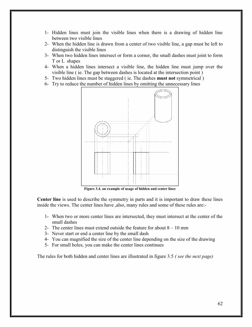
3.2.5 Hidden and center lines
As said in chapter one, the hidden lines are used to draw the invisible lines. In views
drawing, hidden lines are too important because it describe an object specifications as shown
in figure 3.4. ( see the next page )
There are some rules that must be followed when a hidden line is being drawn to have a
correct and adequate drawings and some f these rules are:-
62
1- Hidden lines must join the visible lines when there is a drawing of hidden line
between two visible lines
2- When the hidden line is drawn from a center of two visible line, a gap must be left to
distinguish the visible lines
3- When two hidden lines intersect or form a corner, the small dashes must joint to form
T or L shapes
4- When a hidden lines intersect a visible line, the hidden line must jump over the
visible line ( ie. The gap between dashes is located at the intersection point )
5- Two hidden lines must be staggered ( ie. The dashes must not symmetrical )
6- Try to reduce the number of hidden lines by omitting the unnecessary lines
Figure 3.4. an example of usage of hidden and center lines
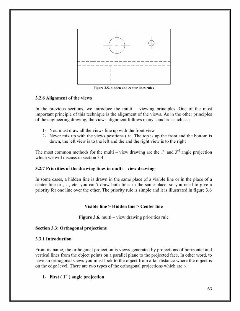
Center line is used to describe the symmetry in parts and it is important to draw these lines
inside the views. The center lines have ,also, many rules and some of these rules are:-
1- When two or more center lines are intersected, they must intersect at the center of the
small dashes
2- The center lines must extend outside the feature for about 8 – 10 mm
3- Never start or end a center line by the small dash
4- You can magnified the size of the center line depending on the size of the drawing
5- For small holes, you can make the center lines continues
The rules for both hidden and center lines are illustrated in figure 3.5 ( see the next page)
63
Figure 3.5. hidden and center lines rules
3.2.6 Alignment of the views
In the previous sections, we introduce the multi – viewing principles. One of the most
important principle of this technique is the alignment of the views. As in the other principles
of the engineering drawing, the views alignment follows many standards such as :-
1- You must draw all the views line up with the front view
2- Never mix up with the views positions ( ie. The top is up the front and the bottom is
down, the left view is to the left and the and the right view is to the right
The most common methods for the multi – view drawing are the 1st and 3
rd angle projection
which we will discuss in section 3.4 .
3.2.7 Priorities of the drawing lines in multi – view drawing
In some cases, a hidden line is drawn in the same place of a visible line or in the place of a
center line or ,…, etc. you can’t draw both lines in the same place, so you need to give a
priority for one line over the other. The priority rule is simple and it is illustrated in figure 3.6
Visible line > Hidden line > Center line
Figure 3.6. multi – view drawing priorities rule
Section 3.3: Orthogonal projections
3.3.1 Introduction
From its name, the orthogonal projection is views generated by projections of horizontal and
vertical lines from the object points on a parallel plane to the projected face. In other word, to
have an orthogonal views you must look to the object from a far distance where the object is
on the edge level. There are two types of the orthogonal projections which are :-
1- First ( 1st ) angle projection
64
2- Third ( 3rd
) angle projection
Both of these projection types will be discussed in following sub-sections
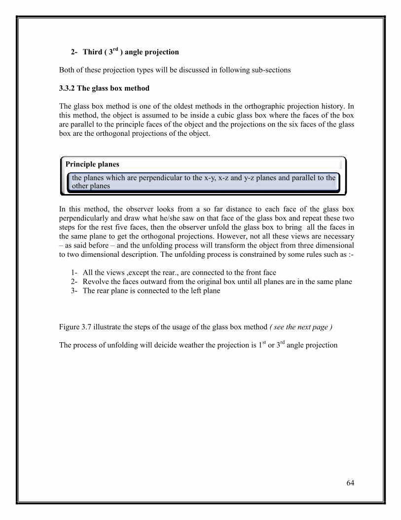
3.3.2 The glass box method
The glass box method is one of the oldest methods in the orthographic projection history. In
this method, the object is assumed to be inside a cubic glass box where the faces of the box
are parallel to the principle faces of the object and the projections on the six faces of the glass
box are the orthogonal projections of the object.
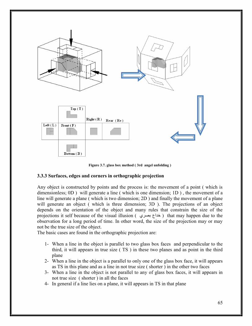
In this method, the observer looks from a so far distance to each face of the glass box
perpendicularly and draw what he/she saw on that face of the glass box and repeat these two
steps for the rest five faces, then the observer unfold the glass box to bring all the faces in
the same plane to get the orthogonal projections. However, not all these views are necessary
– as said before – and the unfolding process will transform the object from three dimensional
to two dimensional description. The unfolding process is constrained by some rules such as :-
1- All the views ,except the rear., are connected to the front face
2- Revolve the faces outward from the original box until all planes are in the same plane
3- The rear plane is connected to the left plane
Figure 3.7 illustrate the steps of the usage of the glass box method ( see the next page )
The process of unfolding will deicide weather the projection is 1st or 3
rd angle projection
Principle planes
the planes which are perpendicular to the x-y, x-z and y-z planes and parallel to the other planes
65
Figure 3.7. glass box method ( 3rd angel unfolding )
3.3.3 Surfaces, edges and corners in orthographic projection
Any object is constructed by points and the process is: the movement of a point ( which is
dimensionless; 0D ) will generate a line ( which is one dimension; 1D ) , the movement of a
line will generate a plane ( which is two dimension; 2D ) and finally the movement of a plane
will generate an object ( which is three dimension; 3D ). The projections of an object
depends on the orientation of the object and many rules that constrain the size of the
projections it self because of the visual illusion ( خداع بصري ) that may happen due to the
observation for a long period of time. In other word, the size of the projection may or may
not be the true size of the object.
The basic cases are found in the orthographic projection are:
1- When a line in the object is parallel to two glass box faces and perpendicular to the
third, it will appears in true size ( TS ) in these two planes and as point in the third
plane
2- When a line in the object is a parallel to only one of the glass box face, it will appears
as TS in this plane and as a line in not true size ( shorter ) in the other two faces
3- When a line in the object is not parallel to any of glass box faces, it will appears in
not true size ( shorter ) in all the faces
4- In general if a line lies on a plane, it will appears in TS in that plane
66
5- When a surface in the object is perpendicular to two of the glass box faces, it will
appears in that faces as a edge and in the third face as a TS
6- When a surface in the object is perpendicular to one of the glass box faces, it will
appears in that face as a edge and in the other faces as planes in not TS
7- When a surface is not perpendicular to any faces, it will appears as planes in not TS in
all faces
The other cases are a product of these cases. However, the most important thing here is to
understand the principles of orthographic projection when the object is fitted in the glass box
where the most of its planes are principle. For the other cases where the most of the object
planes aren’t principles, other projection methods , such as the oblique projection, is used.
3.3.4 Adjacent areas and similar shapes of a surface
The 3D object , in many cases, is constructed by many other small other objects, for example,
the vehicle engine is assembly of many components which are pieces of other small principle
objects such as cubic, cones, … , etc.
Due to the similarity between the principle objects, their projections will be similar and that
known as the similar shapes in a surface( eg. The rectangle shape, triangle shape, … , etc )
3.3.5 45o line ( miter line )
In orthographic projection, many dimensions are repeated in two or more views and because
of that you can draw the dimension one time and project it in the other views. This procedure
will reduce the time and the effort and will generate more adequate drawing. To project a
dimension on the other views, a magic line called the miter line or the 45o line. This line is
used due to the right angle theories as illustrated in figure 3.8.
In summary
All the objects however what its complicity is constructed by a basic or principle objects and the projection of these objects will generate what known as the adjacent areas

67
Figure 3.8. miter line principle
The importance of this line will be shown later
3.3.6 orthographic projection techniques
After introducing a brief description in the previous sections, now it is the time to introduce
the techniques behind this method of engineering drawing. As in other engineering drawing
methods, orthographic projection has many techniques to reduce the time and the effort and
to generate a correct and adequate drawing to be easy to be read by other engineers. In the
orthographic projection, the sequence of steps is important to prevent the wasting in
redrawing or the correction of the mistakes in the drawn views. The adequate sequence for
the orthographic projection drawing is :-
1- Fix the paper on the drawing table ( see section 1.8 )
2- Calculate the maximum dimension in the object. This step will help you in zoning
your paper for the optimal situation
3- Divide the paper according to the views of maximum dimension to four sections not
necessarily to be equal using phantom lines and if you found that your paper is not
enough use a scale
4- Locate where the front, top and side view ( left or right ) will be and then draw the
miter line by 0.5 mm 2H pencil from the center of the dividing lines intersection point
5- Draw a free hand sketch of the views on an external sheet of paper and be carful for
the visible and hidden lines. This step will take a few minutes but it will reduce the
waste of time and effort in correcting the future mistakes
6- Chose the most descriptive view and draw it on the drawing sheet by only repeating
an accurate engineering drawing for your hand sketch
7- When you finish the first view, project the common dimensions to the second view
and finish the other dimensions
68
8- The last view is ,commonly, projected from the drawn two views with the assistant of
the miter line
In some cases, you chose the most descriptive view but there are some details in this view
can be described better in other views. So, the descriptive view is the view that has the most
details in the object not necessary all details. From the other hand, some view may have a
unique detail that must be included after finishing the projections.
It is better , in many cases, to draw the outlines of all views and then the descriptive details
are drawn ; first the visible lines then the hidden lines.
Remember that all the details in the object must be projected ( ie. All dimensions must be
drawn) and because of that , it is preferred to check your drawing when you finish.
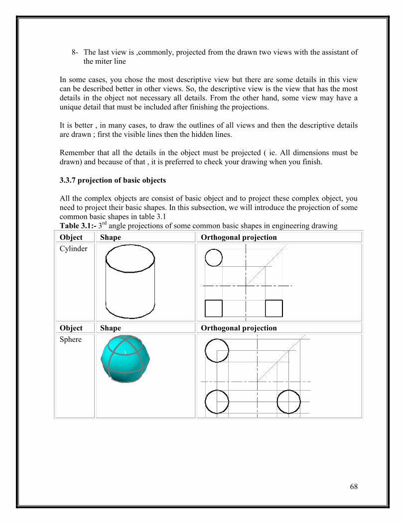
3.3.7 projection of basic objects
All the complex objects are consist of basic object and to project these complex object, you
need to project their basic shapes. In this subsection, we will introduce the projection of some
common basic shapes in table 3.1
Table 3.1:- 3rd
angle projections of some common basic shapes in engineering drawing
Object Shape Orthogonal projection
Cylinder
Object Shape Orthogonal projection
Sphere

69
Cube
Cone
Object Shape Orthogonal projection
Pyramid
Hole Through
drill
3.3.8 Alternative position of views

71
in some cases where a flat object is being drawn using the traditional arrangement, a lot of
space may be wasted and to reduce the waste in space, you can imagine the side or profile of
the glass box is hinged with the top instead of the front which mean that the side view and
the miter line will change places.
3.3.9 partial views
In some cases where there is a symmetry or there are views aren’t necessary in the
projection, some of the views aren’t drawn to reduce the waste in space, time and effort. In
theses cases, the break line is used if the undrawn details are not necessary and either break
or center line is used if there is symmetry in the view. However, it is preferred to draw all the
details and all the views. An example of symmetry is illustrated in figure 3.9
Figure 3.9. Partial viewing: symmetry case
Section 3.4: First and third angle views
As said in the previous chapter, the first system we use to describe an object by two
dimensional drawings is the ‘ descriptive geometry ‘ which was invented in the 18th
century
by a French mathematician and engineer called Gaspand Monge. The descriptive geometry is
the basic of the orthogonal projection. Nowadays, two types or methods of orthographic
projection based on Monge’s method are used and these types are the first and third angle
projections
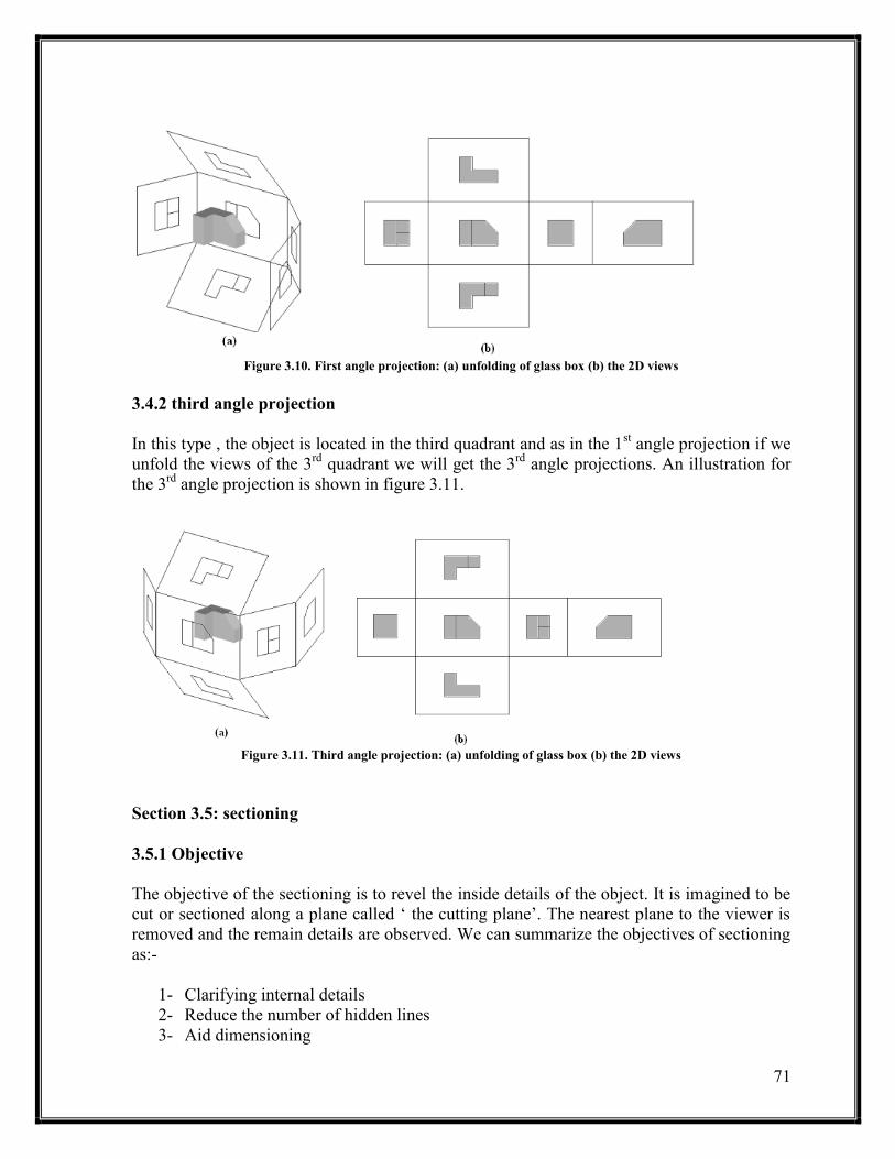
3.4.1 First angle projection
This method is common in Europe. Any object is putted in the first quadrant and viewed is
projected by the first angle method. If we unfold the views for the first quadrant, we will get
a 1st angel projection. An illustration for the 1
st angle projection is shown in figure 3.10. ( see
the next page )
71
Figure 3.10. First angle projection: (a) unfolding of glass box (b) the 2D views
3.4.2 third angle projection
In this type , the object is located in the third quadrant and as in the 1st angle projection if we
unfold the views of the 3rd
quadrant we will get the 3rd
angle projections. An illustration for
the 3rd
angle projection is shown in figure 3.11.
Figure 3.11. Third angle projection: (a) unfolding of glass box (b) the 2D views
Section 3.5: sectioning
3.5.1 Objective
The objective of the sectioning is to revel the inside details of the object. It is imagined to be
cut or sectioned along a plane called ‘ the cutting plane’. The nearest plane to the viewer is
removed and the remain details are observed. We can summarize the objectives of sectioning
as:-
1- Clarifying internal details
2- Reduce the number of hidden lines
3- Aid dimensioning

72
4- Show cross – sectioning shape
5- Clarifying an assembly
3.5.2 lines in sectioning
As said before, one of the objectives for doing sectioning is to reduce the number of the
hidden lines. However, there are other lines that are involved and each line has its own
function and specifications. The most interesting lines are:-
Visible line:- all the visible lines reveled after the removing of one half must be drawn
Hidden lines:- in the section view ( ie. The view where the cutting plane is touching ), there
must be no hidden lines. So, you change the revel lines to visible lines and forget about the
other lines
Cutting plane line:- see chapter one
Hatching lines:-
a- Hatching lines must indicates the material type
b- A typical hatching lines ( that what we will use in this course ) is a 3mm 2H parallel
inclined lines by 45o with separating distance of 8mm
c- The hatching line must start from a visible line and end by another visible line
d- The hidden lines must not intersect with a hatching lines
e- Changing the hatching lines means changing the material types
f- The hatching lines must be uniformed in thickness and intensity
g- When the hatching lines start and end form 45o inclined lines, the angle of the
hatching lines must be changed ( eg. 40o )
3.5.3 Sectioning techniques
To do a sectioning, you need to follow these procedures
1- Draw all the views except the sectioning view as in regular projection
2- Draw the cutting line in its particular view ( ie. The view where the cutting plane
appear as an edge )
3- Draw the sectioning view and in this time draw only the visible lines
4- Imagine the cutting plane cuts the object
5- Remove the part that in opposite direction to the cutting line arrow
6- Look to the remain part in the same direction of the cutting line arrow
7- Change the hidden lines to visible lines
8- Hatch when the cutting plane touch a material
3.5.4 Section types
Note
In some analogs, even the planes that are a material and not be touched by the cutting plane are been hatched to indicate a material for a manufacturing reasons
73
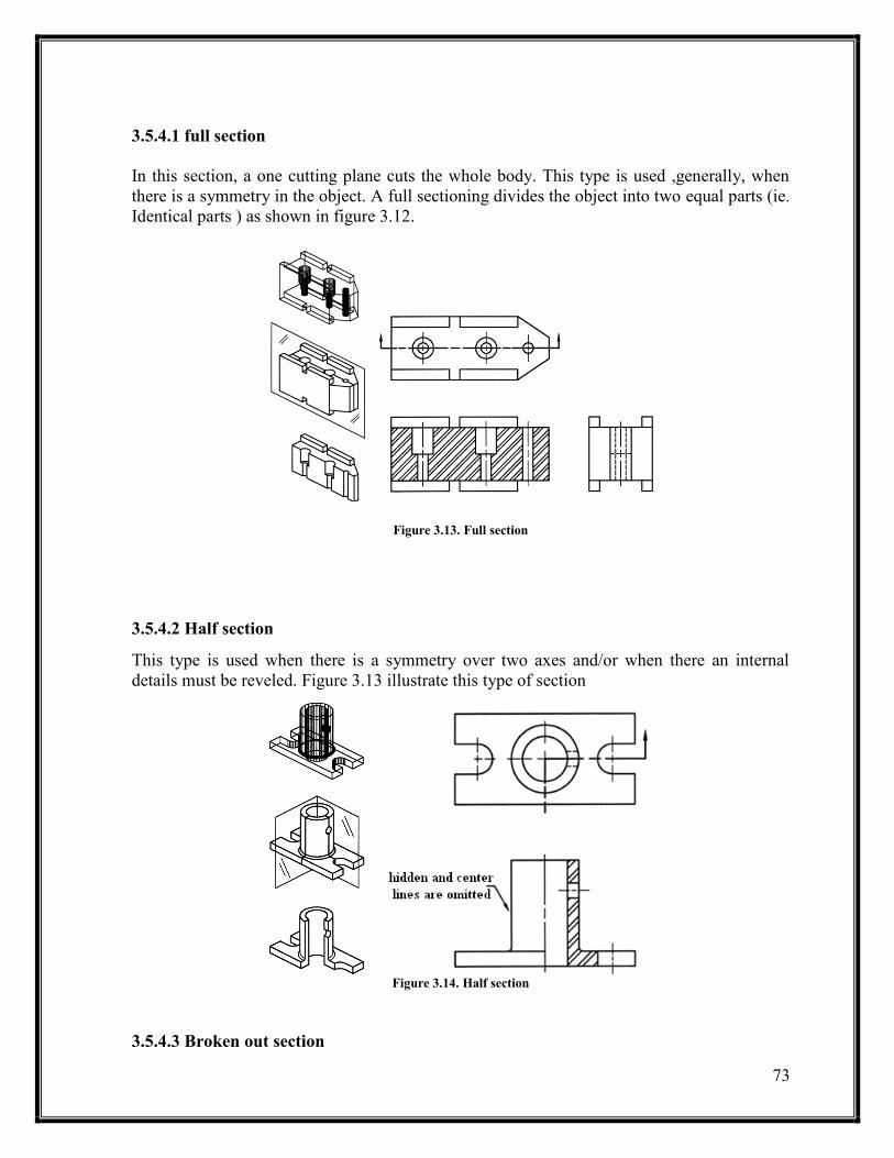
3.5.4.1 full section
In this section, a one cutting plane cuts the whole body. This type is used ,generally, when
there is a symmetry in the object. A full sectioning divides the object into two equal parts (ie.
Identical parts ) as shown in figure 3.12.
Figure 3.13. Full section
3.5.4.2 Half section
This type is used when there is a symmetry over two axes and/or when there an internal
details must be reveled. Figure 3.13 illustrate this type of section
Figure 3.14. Half section
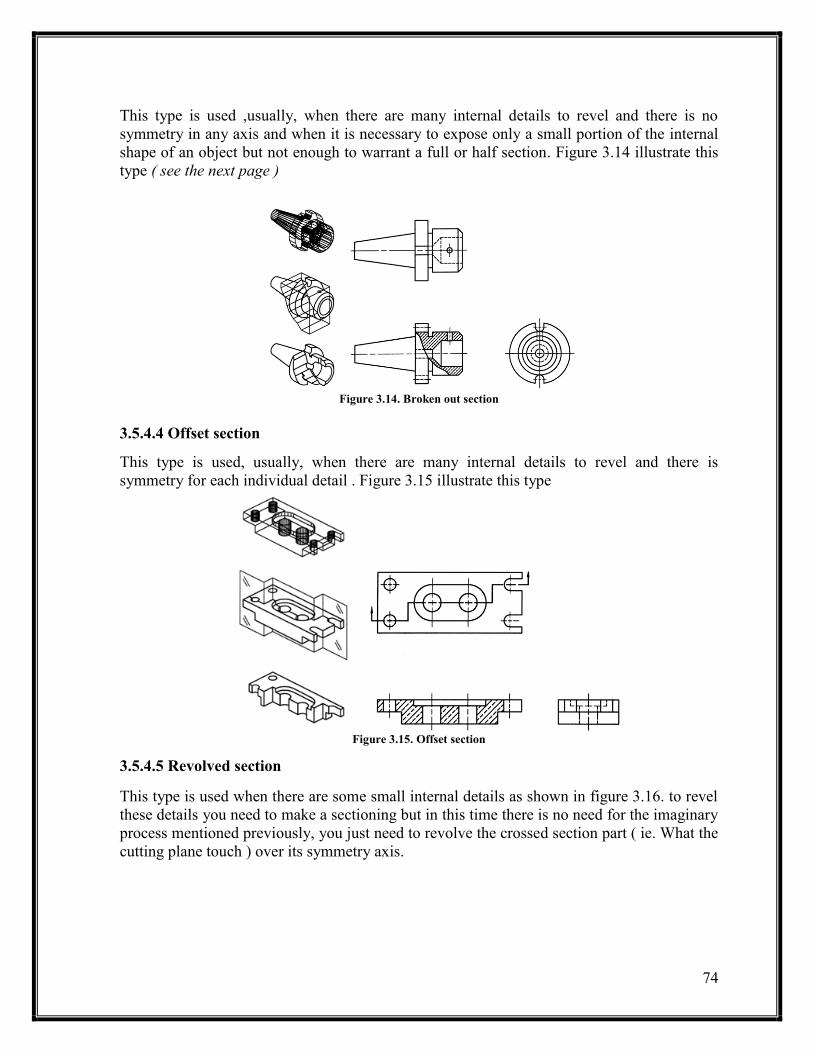
3.5.4.3 Broken out section
74
This type is used ,usually, when there are many internal details to revel and there is no
symmetry in any axis and when it is necessary to expose only a small portion of the internal
shape of an object but not enough to warrant a full or half section. Figure 3.14 illustrate this
type ( see the next page )
Figure 3.14. Broken out section
3.5.4.4 Offset section
This type is used, usually, when there are many internal details to revel and there is
symmetry for each individual detail . Figure 3.15 illustrate this type
Figure 3.15. Offset section
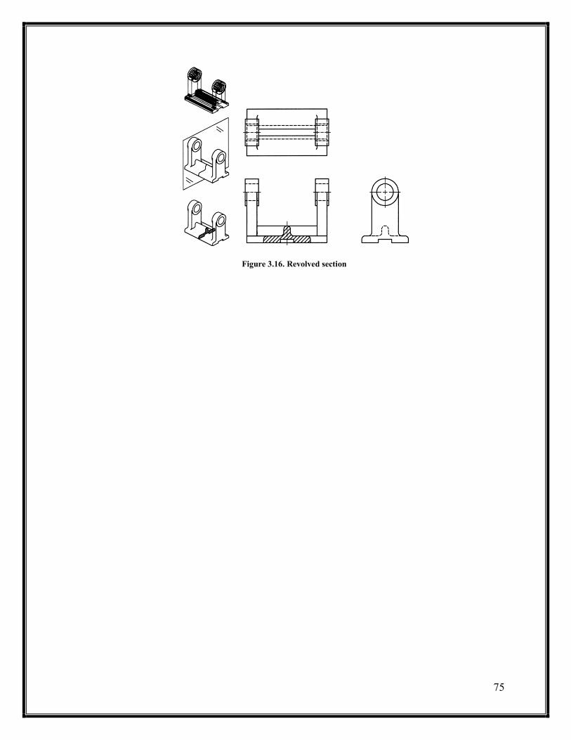
3.5.4.5 Revolved section
This type is used when there are some small internal details as shown in figure 3.16. to revel
these details you need to make a sectioning but in this time there is no need for the imaginary
process mentioned previously, you just need to revolve the crossed section part ( ie. What the
cutting plane touch ) over its symmetry axis.
75
Figure 3.16. Revolved section

76
CHAPTER FOUR
DIMENSIONING
Section 4.1: Introduction
section 4.2: dimensioning rules
Section 4.3: common dimensioning types and cases
4.3.1 dimensioning a feature not drawn to scale
4.3.2 chain dimensioning and auxiliary dimensioning
4.3.3 parallel dimensioning
4.3.4 Running dimensioning
4.3.5 Dimensioning a circle
4.3.6 arc dimensioning
4.3.6 Angular dimensioning
Chapter three and four problems
77
CHAPTER FOUR: DIMENSIONING
Section 4.1: Introduction
Dimensioning is the last part of the projection drawing. It has its own importance and should
be drawn following standards to produce an adequate drawing which can be easily read and
met all the stages of manufacturing. Dimensioning helps the manufacturer to know the size,
location, ..etc. of the object components. Each object is composed of many other simple
objects and so, the views been drawn for an object is composed of many simple shapes such
as circles, squares, rectangles, triangles, …, etc. In all manufacturing processes the
manufacturer needs to know the size of each simple shape ( ie. Width, height, depth,
diameter or radius ), its location ( ie. The x, y and z dimensions ) and surface texture ( ie.
Material, mechanical properties, …, etc). To specify the size of a component of the object,
you need to know its geometry and to specify the location, you need to define a datums to
take the position from. You can chose the datums that you want, however, you can’t take the
edges of the glass box or an inadequate internal edges. Its preferable to use the object
outlines for this prepuce. To specify the surface texture, you need to use a leader line with.
noting system
section 4.2: dimensioning rules
As in all engineering drawing principles, dimensioning is governed by many standards. The
best standard that we will use here is the British Standard ( BS ) 8888 because it covers all
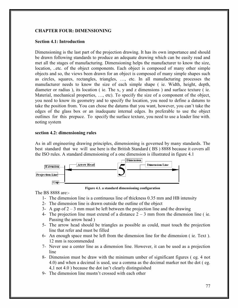
the ISO rules. A standard dimensioning of a one dimension is illustrated in figure 4.1
Figure 4.1. a standard dimensioning configuration
The BS 8888 are:-
1- The dimension line is a continuous line of thickness 0.35 mm and HB intensity
2- The dimension line is drawn outside the outline of the object
3- A gap of 2 – 3 mm must be left between the projection line and the drawing
4- The projection line must extend of a distance 2 – 3 mm from the dimension line ( ie.
Passing the arrow head )
5- The arrow head should be triangles as possible as could, must touch the projection
line that refer and must be filled
6- An enough space must be left from the dimension line for the dimension ( ie. Text ).
12 mm is recommended
7- Never use a center line as a dimension line. However, it can be used as a projection
line
8- Dimension must be draw with the minimum umber of significant figures ( eg. 4 not
4.0) and when a decimal is used, use a comma as the decimal marker not the dot ( eg.
4,1 not 4.0 ) because the dot isn’t clearly distinguished
9- The dimension line mustn’t crossed with each other

78
10- Dimension must be drawn horizontal or in manner that can be read if the drawing is
turned clockwise
11- The leader line must end with arrow head. In most cases, the leader line is used to
give a hole dimension. In this case , the arrow head must be towards the center of the
hole and must end at the circumferences of the hole
There are recommendations for dimensioning to simplify the process and to ensure that there
are no mistakes that will cost a waste in time and effort. Some of these recommendations
are:-
1- Understand the shapes in the drawing to be able to chose the best dimensioning
situation
2- Notes the space you have ad the complicity of the drawing to have a picture of where
are the best possible positions for the dimensions
3- Placing the dimensions outside the drawing outline is the best choice
4- You can use a parallel or chain dimensioning types which one is applied, these types
of dimensioning are discussed clearly later
5- Don’t repeat a common dimension between two views instead put this dimension
between these two views
6- In projection views, never extend the projection lines of the dimension to cross the
folding lines
7- Try to make the dimension as could as possible orthogonal
Figure 4.2 illustrate an example of the correct and in correct dimensioning
Section 4.3: common dimensioning types and cases
4.3.1 dimensioning a feature not drawn to scale
When you draw a feature without scale and you want not to create a misunderstanding to
your drawing, you must underline the dimension as shown in figure 4.3
Figure 4.3. dimensioning of a feature not drawn to scale
Remember
how is your drawing is good and clean is the standard of your adequacy and your engineering sense

79
Figure 4.2. A correct and incorrect dimensioning example
4.3.2 chain dimensioning and auxiliary dimensioning
Chain dimensioning means: the end projection lines for ne dimension is the beginning
projection line for the adjacent dimension as illustrated in figure 4.4
Figure 4.4. Chain dimensioning and auxiliary dimensioning type
This type of dimensioning is used where:-
1- The possible accumulation of the tolerances dose not endanger the function of the
part ( ie when its been manufactured, it will not be a significant problem )
2- When there is no enough space ( eg. The dimension must be drawn between the
feature outline and the folding lines )
In this type of dimensioning, many rules must be followed and these rules are:-
1- The dimensions must be aligned to each other ( ie. Must be in the same level )
81
2- An auxiliary dimension ( ie. The accumulation dimension ) is used when there is a
suspects in the accuracy of the manufacturing process will be effective
3- Never use this dimensioning when the dimensions are small to keep the drawing clear
and clean
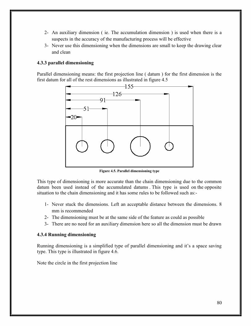
4.3.3 parallel dimensioning
Parallel dimensioning means: the first projection line ( datum ) for the first dimension is the
first datum for all of the rest dimensions as illustrated in figure 4.5
Figure 4.5. Parallel dimensioning type
This type of dimensioning is more accurate than the chain dimensioning due to the common
datum been used instead of the accumulated datums . This type is used on the opposite
situation to the chain dimensioning and it has some rules to be followed such as:-
1- Never stuck the dimensions. Left an acceptable distance between the dimensions. 8
mm is recommended
2- The dimensioning must be at the same side of the feature as could as possible
3- There are no need for an auxiliary dimension here so all the dimension must be drawn
4.3.4 Running dimensioning
Running dimensioning is a simplified type of parallel dimensioning and it’s a space saving
type. This type is illustrated in figure 4.6.
Note the circle in the first projection line

81
Figure 4.6. Running dimensioning type
4.3.5 Dimensioning a circle
A circle is been dimensioned by its diameter or radius and its center location. The symbol
‘Φ’ is used for the diameter and the letter ‘R’ is used for radius. The position of the center is
located by tow dimensions from two datums.
When the circle is large enough, the dimension is drawn inside the circle
When the circle is small, the dimension line is drawn inside the circle and the
dimension is drawn outside
When the circle is too small, a two crossing lines instead of the center lines are used
and the dimension is drawn with an arrow pointed to the circle or the dimension can
be drawn orthogonally as shown in figure 4.7.
Figure 4.7. Circle dimensioning
4.3.6 arc dimensioning
As said before, the an arc is a part of a circle and to dimension it you need to define its radius
and the location of the center as shown in figure 4.8.
Figure 4.8. arc dimensioning
4.3.6 Angular dimensioning
Note
The best dimensioning is when there are projection views are involved is the orthogonal ( ie. Vertical or horizontal ) dimensioning
When the space isn’t enough for dimension line, you can reverse the arrow heads to be outside the projection lines

82
Angels are the radian measurement between two intersection lines and so to dimension an
angle you need to know its value. A typical cases of dimensioning are shown in figure 4.9.
Figure 4.9. angular dimensioning
Problem 1:- Draw the projection for the following objects on an A3 sheet and dimension
it correctly . Be awareness to the sectioning
4.1
4.2
Chapter Three and Four Problems
83
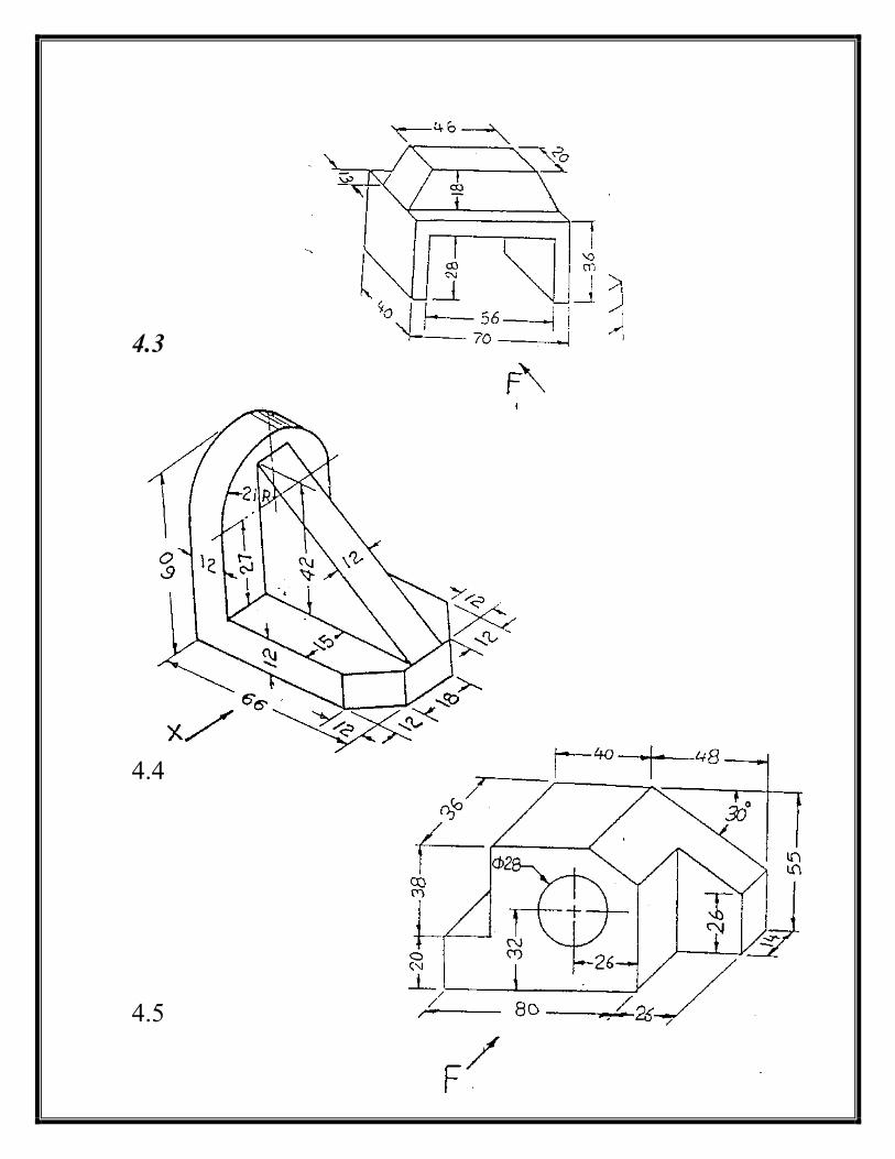
4.3
4.4
4.5
84
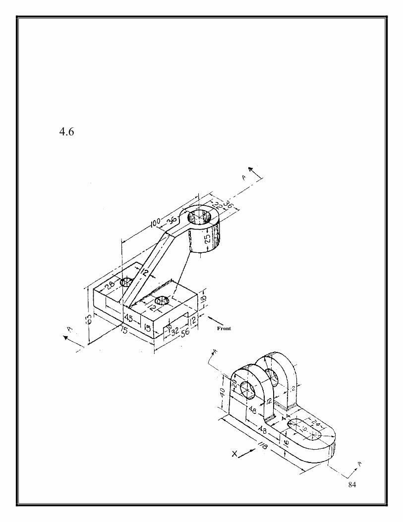
4.6

85

86
4.10
4.11

87
4.12
4.13

88
4.14
4.15
89
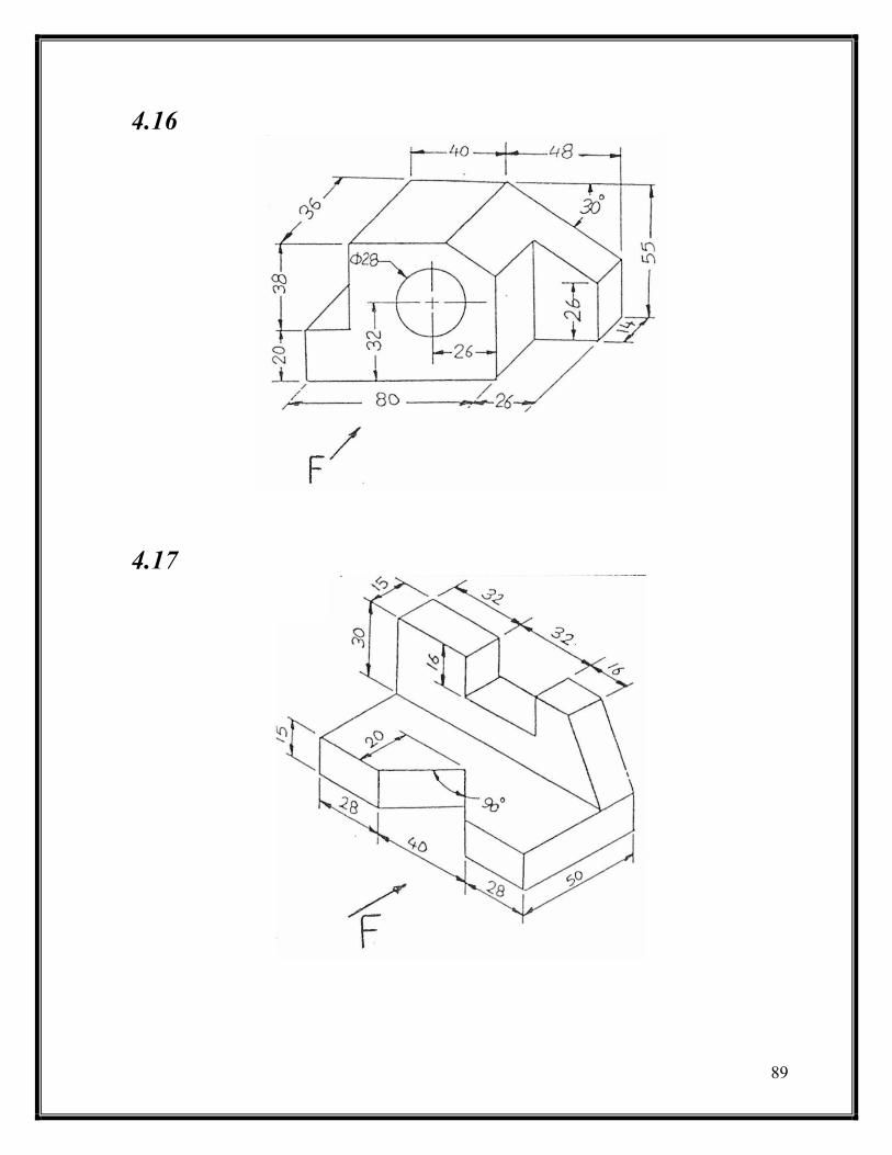
4.16
4.17
91
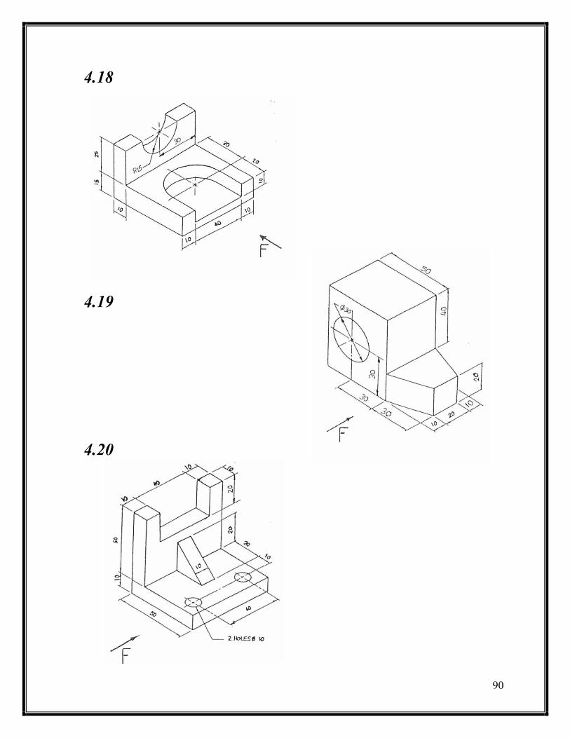
4.18
4.19
4.20

91
4.21
4.22
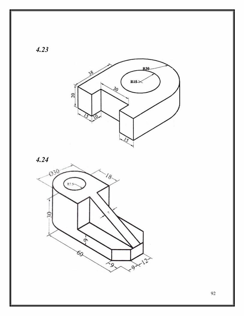

94
4.27
4.28

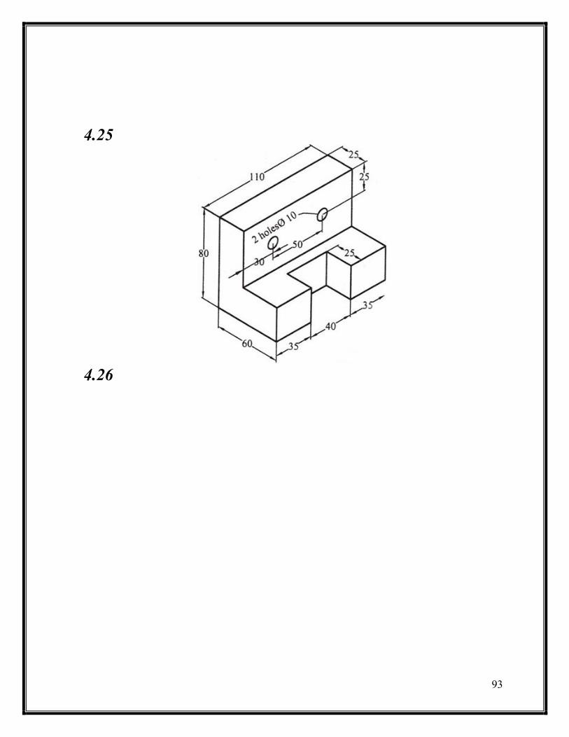
95
4.29
96
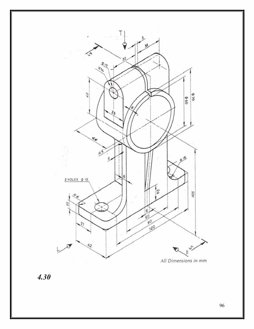
4.30

97
4.31

98

99
4.32
4.33
111
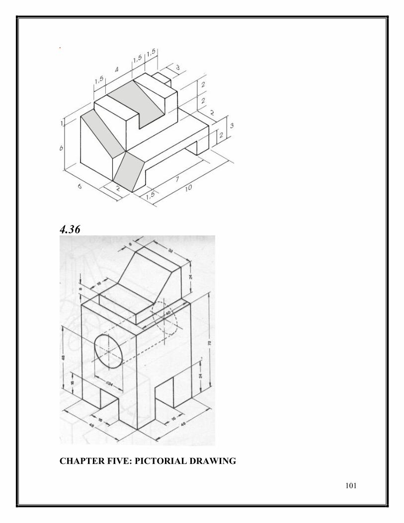
4.36
CHAPTER FIVE: PICTORIAL DRAWING
112
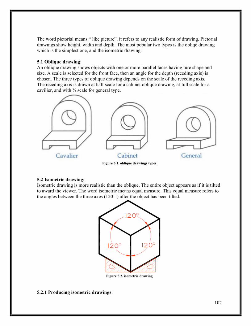
The word pictorial means “ like picture”. it refers to any realistic form of drawing. Pictorial
drawings show height, width and depth. The most popular two types is the obliqe drawing
which is the simplest one, and the isometric drawing.
5.1 Oblique drawing:
An oblique drawing shows objects with one or more parallel faces having ture shape and
size. A scale is selected for the front face, then an angle for the depth (receding axis) is
chosen. The three types of oblique drawing depends on the scale of the receding axis.
The receding axis is drawn at half scale for a cabinet oblique drawing, at full scale for a
cavilier, and with ¾ scale for general type.
Figure 5.1. oblique drawings types
5.2 Isometric drawing:
Isometric drawing is more realistic than the oblique. The entire object appears as if it is tilted
to award the viewer. The word isometric means equal measure. This equal measure refers to
the angles between the three a es (1 0 ) after the object has been tilted.
Figure 5.2. isometric drawing
5.2.1 Producing isometric drawings:

113
1- Using the T squre draw a hirizantal line, the by the triangle draw a vertical line at the
center of the horizontal one.
Figure 5.3. producing isometric step 1
2- Using the T-square and the 30 0 triangle draw 30 line to the right, and another to
the left.
Figure 5.4. producing isometric step 2
3- Plot the principal height on the z axis, width on the x axis, and depth on the y axis.
Figure 5.5. producing isometric step 3
114
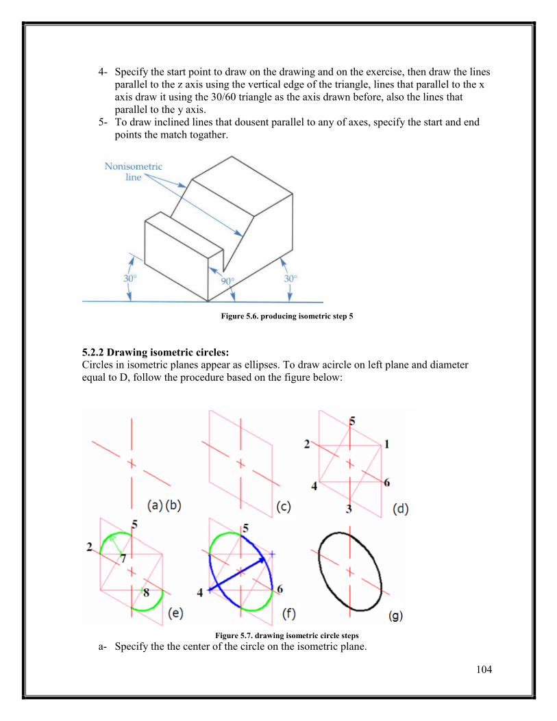
4- Specify the start point to draw on the drawing and on the exercise, then draw the lines
parallel to the z axis using the vertical edge of the triangle, lines that parallel to the x
axis draw it using the 30/60 triangle as the axis drawn before, also the lines that
parallel to the y axis.
5- To draw inclined lines that dousent parallel to any of axes, specify the start and end
points the match togather.
Figure 5.6. producing isometric step 5
5.2.2 Drawing isometric circles:
Circles in isometric planes appear as ellipses. To draw acircle on left plane and diameter
equal to D, follow the procedure based on the figure below:
Figure 5.7. drawing isometric circle steps
a- Specify the the center of the circle on the isometric plane.

115
b- Draw tow center lines from the center, vertical and 30 to left.
c- Draw a square of edge length equal D , and the center lines should devide each side
by half.
d- Draw the lines 1-2, 1-3, 4-5 and 4-6.
e- Point 7 is the intersection between lines 1-2 and 4-5, and similarly point 8 the
intersection of 1-3 and 2-6. Set your compass to the distance 7-2, draw an arc with
center at 7 from point 2 to 5, do the same from point 8.
f- Set your compass to the distance 1-2, draw an arc with center 1, from 2 to 3, and
same thing from point 4.
5.3 Orthographic to isometric drawings:
To convert an orthographic projection views to an isometric drawing (2D views to 3D model)
read the hints below:
1- Identify major features and overall dimensions.
2- Draw the axes, then draw a boundary box using construction lines.
3- Only measure dimensions along aprimary axes
4- Do not directly transfer angles from a Multiview to a pictorial.
5- Sketch faces roughly, starting with normal faces.
For example if we have the orthographic views below
Figure 5.8. ortho to iso example
To draw the isometric drawing :
1- Draw isometric axes.
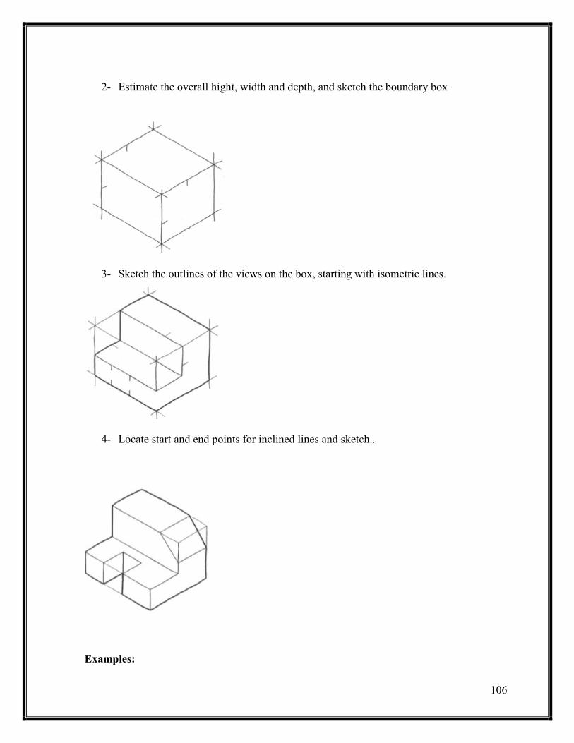
116
2- Estimate the overall hight, width and depth, and sketch the boundary box
3- Sketch the outlines of the views on the box, starting with isometric lines.
4- Locate start and end points for inclined lines and sketch..
Examples:
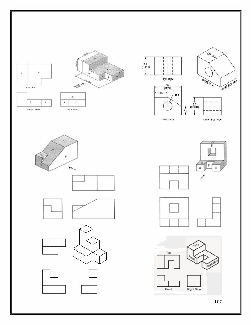
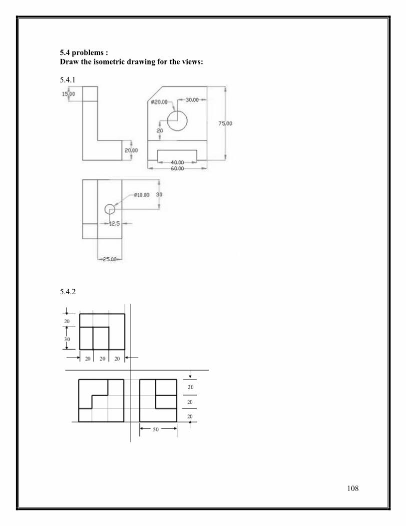
118
5.4 problems :
Draw the isometric drawing for the views:
5.4.1
5.4.2

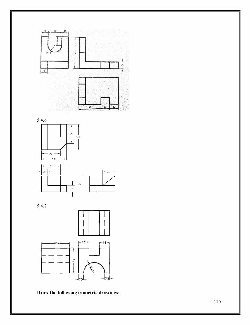
111
5.4.6
5.4.7
Draw the following isometric drawings:
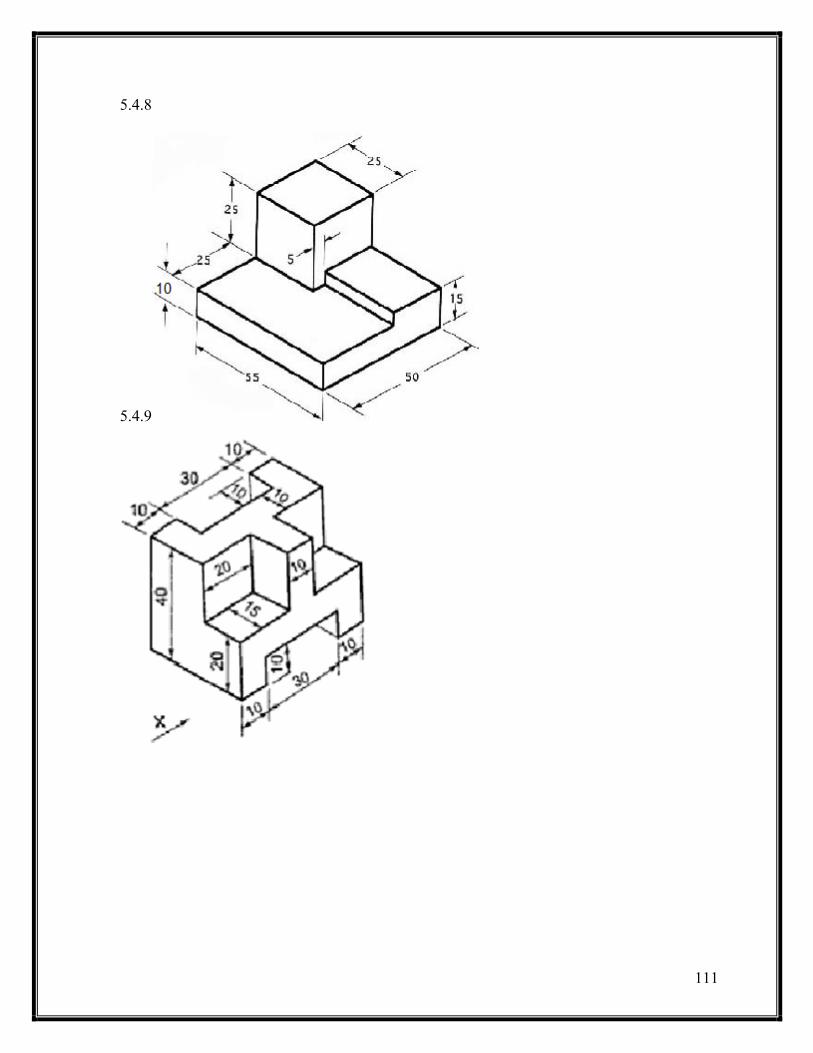
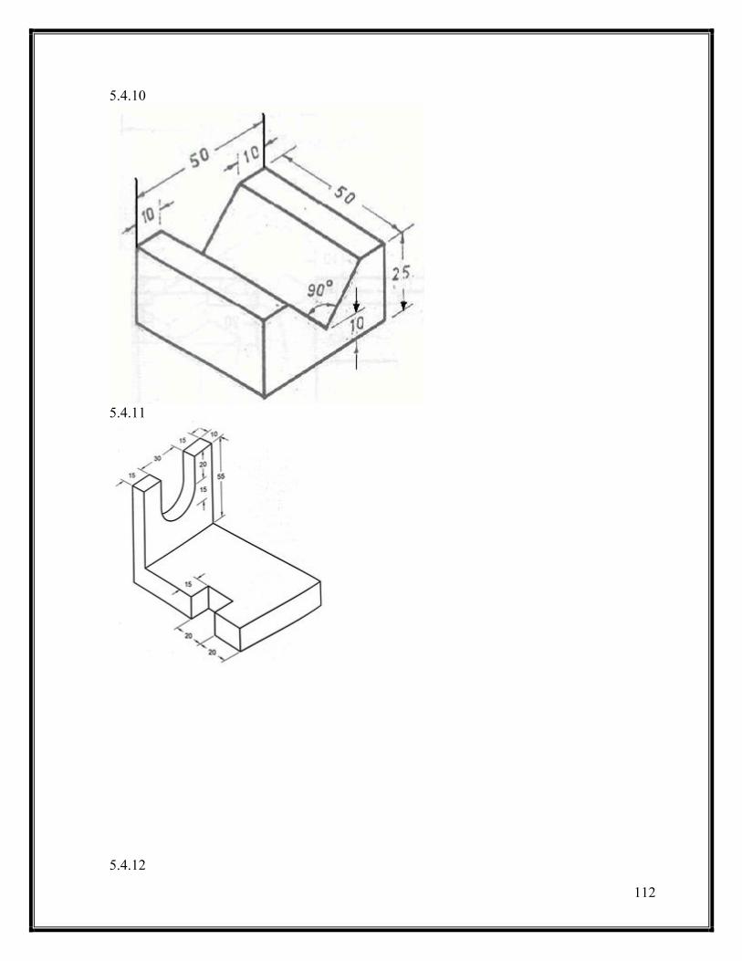

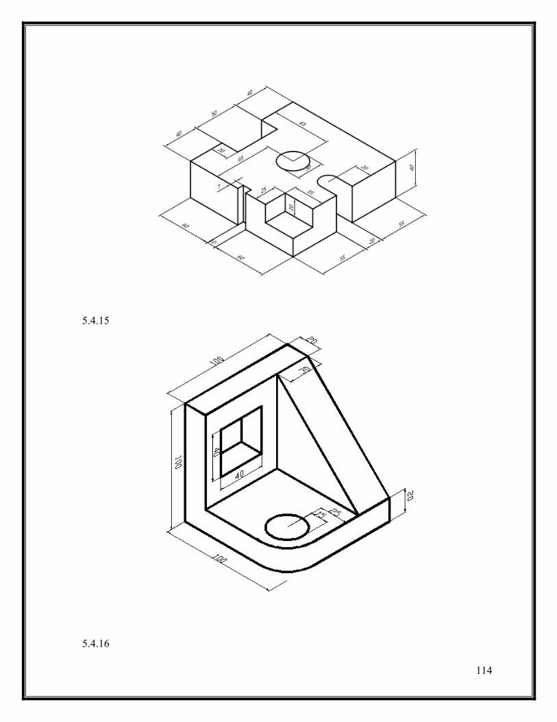
114
5.4.15
5.4.16
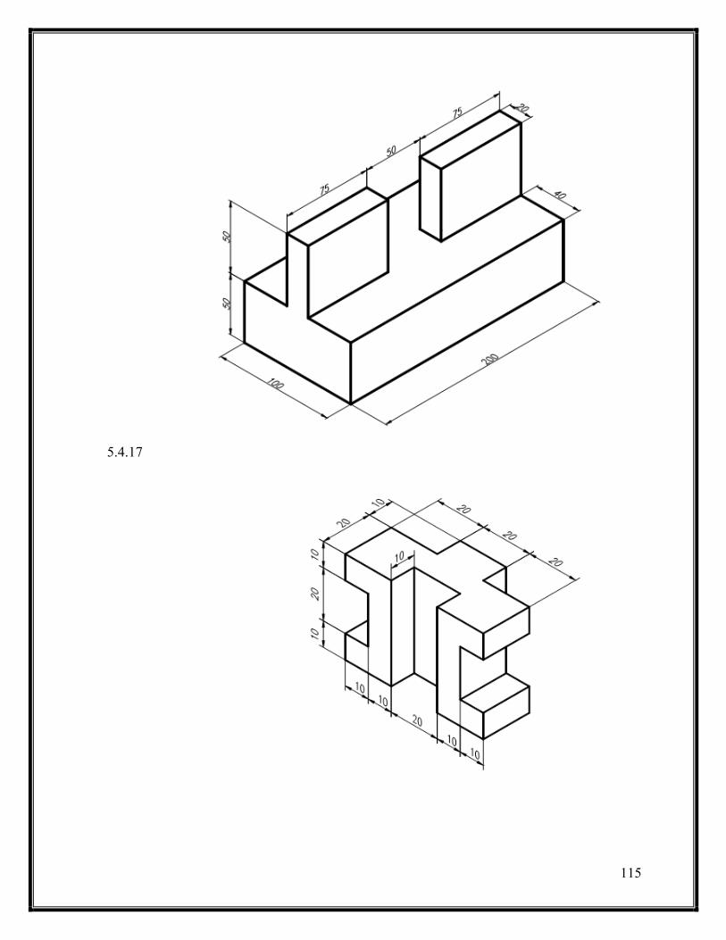
115
5.4.17


