
PERPUSTAKAAN UMP
U DO I11 IO Iffi Iffi II 1111 IU 0I 11 IOU 0000092448
EFFECTS OF SQUARE OPENINGS N REINFORCED CONCRETE DEEP BEAMS
'/ NOOR RAHAMAN BIN YAHYA
Thesis submitted in fulfilment of the
requirements for the award of the degree of
B. Eng (Hons.) Civil Engineering
Faculty of Civil Engineering & Earth Resources
UNIVERSITY MALAYSIA PAHANG
JUNE 2014

vi
ABSTRACT
Reinforced concrete (RC) deep beams are usually used in tall buildings' or offshore structures. The presence of web opening in such beams can often be necessary to accommodate crucial services, for instance ventilating as well as air conditioning ducts. This research was conducted to study the effects of opening in RC deep beams with various sizes of Openings as a test parameter. The shape of choice is square opening. The square openings were placed at the top of shear span near support. A total six deep beams with same dimensions (100 mm x 500 mm)and the total length of 1200 mm were cast. Three control deep beams and the remaining deep beam with openings with size of 150x150 mm, 200x200 mm and 250x250 mm were studied. The beams were tested to failure under 4-point bending. The results obtained from the test including load-deflection behaviour, and crack pattern. The reinforced concrete deep beams with openings develop shear-diagonal cracks at the openings corner, due to the stress concentration at sharp edges.. The crack pattern development varies with opening sizes. The cracking development increased as the size of openings increased. The presence of openings in RC deep beams caused significant reduction in the beam strength. As compared to solid deep beam, the reduction of beam strength falls in the range of 43% - 82%. As for RC deep beams with openings, losses in beam capacity about 43%, 51%, and 82% in beam DBS1, DBS2, and DBS3, respectively were obtained. The size of opening plays a crucial part in this study. The larger the opening size, the more severe crack pattern was observed.
vii
ABSTRAK
Konkrit bertetulang (RC) rasuk dalam biasanya digunakan dalam bangunan tinggi 'atau struktur luar pesisir. Kehadiran pembukaan web di rasuk itu sering boleh menjadi perlu untuk menampung perkhidmatan penting, misalnya pengalihudaraan serta saluran penyaman udara. Kajian mi telah dijalankan untuk mengkaji kesan pembukaan di rasuk dalam RC dengan pelbagai saiz bukaan sebagai parameter ujian. Bentuk pilihan adalah pembukaan persegi. Lubang persegi diletakkan di bahagian atas span ricih berhampiran sokongan. Sebanyak enam rasuk dalam dengan dimensi yang sama (100 mm x 500 mm) dan panjang keseluruhan 1200 mm dibuang. Tiga kawalan rasuk dalam dan rasuk dalam baki dengan bukaan dengan saiz 1 50x1 50 mm, 200x200 mm dan 250x250 mm telah dikaji. Rasuk diuji untuk kegagalan di bawah 4-mata lenturan. Keputusan yang diperolehi daripada ujian termasuk tingkah laku beban-pesongan, dan corak retak. Bertetulang rasuk dalam konkrit dengan bukaan membangunkan retak ricih pepenjuru di sudut bukaan, kerana penumpuan tegasan di tepi tajam. Pembangunan corak retak berbeza dengan saiz pembukaan. Pembangunan retak meningkat saiz bukaan meningkat. Kehadiran bukaan di rasuk dalam RC disebabkan pengurangan yang ketara dalam kekuatan rasuk. Berbanding dengan rasuk dalam pepejal, pengurangan kekuatan rasuk jatuh dalam lingkungan 43% - 82%. Bagi RC rasuk dalam dengan bukaan, kerugian dalam kapasiti rasuk kira-kira 43%, 51%, dan 82% pada DBS1 rasuk, DBS2, dan DBS3, masing-masing telah diperolehi. Saiz pembukaan memainkan peranan yang penting dalam kajian mi. Semakin besar saiz pembukaan, corak retak lebih teruk diperhatikan.

viii
TABLE OF CONTENTS
SUPERVISOR'S DECLARATION
STUDENT'S DECLARATION
ACKNOWLEDGEMENT
ABSTRACT
ABSTRAK
TABLE OF CONTENTS
LIST OF TABLES
LIST OF FIGURES
LIST OF SYMBOLS
LIST OF ABBREVIATIONS
CHAPTER 1 INTRODUCTION
1.1 Introduction I
1.2 Problem Statement 2
1.3 Objectives 3
1.4 Scope of Study 3
1.5 Significance of Study 4
CHAPTER 2 LITERATURE REVIEW 5
2.1 Introduction 5
2.2 Behavior of Deep Beam Without Opening 6
2.3 Behavior of Deep Beam With Web Opening 6 2.4 Crack Pattern
2.5 Load-Deflection Curve
2.6 Opening Effect 10
2.6.1 Size of Opening 11
2.6.2 Shape of Opening 11
2.6.3 Location of Opening 11

Ix,
CHAPTER 3 METHODOLOGY
13
3.1 Introduction
3.2 Flow Chart
3.3 Deep Beams Preparations
3.3.1 Formwork
3.3.2 Reinforcement
3.3.3 Casting
3.3.4 Curing
3.4 Testing Method
3.4.1 Fresh Concrete
3.4.2 Hardened Concrete
13
14
15
15
16
19
20
21
21
23
CHAPTER 4 RESULT AND DISCUSSION
26
4.1 Introduction 26
4.2 CompressiveTest
27
4.3 Flexural Test
27
4.3.1 Load Deflection Curve 28
4.3.2 Crack Pattern 34
4.4 Comparison of Load Deflection Curve 39
CHAPTER 5 CONCLUSION AND RECOMMENDATION
43
5.1
5.2
5.3
REFERENCES
APPENDICES
APPENDIX A
Introduction
Conclusions
Recommendation For Future Study
43
43
44
45
48
48

LIST OF TABLES
Table No. Title Page
4.1 The result of compressive test 27
4.2 Summary of load deflection curve 39
4.3 The percentage of reduction in ultimate load to SDB1 41

LIST OF FIGURES
Figure No. Title Page
2.1 Schematic diagram deep beam with opening. 7
2.2 Types of cracks in deep beam. 8
2.3 Example graph of load deflection curve. 10
3.1 Research experimental work flow 14
3.2 Deep Beam with Reinforcement Bar Formwork 16
3.3 Detailing for RC Deep Beam 18
3.4 Solid Deep Beam based on detailing 18
3.5 Deep Beam with Opening 19
3.6 Cube casting 19
3.7 Cube Water Curing Method 20
3.8 Wet gunny bags for curing purposes 21
3.9 Slump apparatus 22
3.10 Measurement of slump 23
3.11 Sample of cube tested by compression machine 24
3.12 Compression Machine for compressive test 24
3.13 Magnus Frame 25
3.14 Beam setup under 4-point bending 25
4.1 Load deflection curve for SDB 1 28
4.2 Load deflection curve for SDB2. 29
4.3 Load deflection curve for SDB3. 30
4.4 Load deflection curve for 150 mm square opening. 31
4.5 Load deflection curve for 200 mm square opening. 32
4.6 Load deflection curve for 250 mm square opening 33
4.7 Crack pattern development on SDB1 34
4.8 No crack pattern recorded on SDB2 35
xi

xii
4.9 Crack pattern development on SDB3 35
4.10 Crack pattern development on DBS 1 36
4.11 Crack pattern development on DBS2 37
4.12 Crack pattern development on DBS3 38
4.13 Load deflection curve for three control beam 40
4.14 Load deflection curve from three deep beams with opening 41
and one solid deep beam
4.15 The result from ultimate load and percentage 42
of reduction

LIST OF SYMBOLS
xlii
% Percentage
MPa Mega Pascal
min Millimeter
m3 Meter cubes

LIST OF ABBREVIATIONS
DBS1 Deep Beam Square 1
DBS2 Deep Beam Square 2
DBS3 Deep Beam Square 3
RC Reinforced Concrete
SDB1 Solid Deep Beam 1
SDB2 Solid Deep Beam 2
SDB3 Solid Deep Beam 3
LVDT Linear Variable Displacement Transducer
xlv

CHAPTER 1
INTRODUCTION
1.1 Introduction
These days, deep order design may be actively investigated concerning their
necessity being a construction option has grown to be more evident. Reinforced
concrete (RC) deep beams frequently used in addition to encountered in several
structural as diaphragms, connections, water tanks, precast and to pre-stressed building,
foundations, silos, bunkers, and offshore structures. Deep beams defined as beams span
to depth "Lid" less or add up to 5 with regard to simply supported beams in addition to
2. 5 with regard to continuous beams. In each instances, when the shear span on the
beam "a" will be less or add up to double the depth, it could be processed being a deep
beams. The presence of opening inside the web brings advantages with regards to
minimizing the price of the creating. Deep beams with world wide web opening goal are
with regard to essential services ducts in addition to pipes.
Web openings in a deep beam significantly affect its structural behavior as
demonstrated in previous studies (Kong and Sharp 1977; Kong et al. 1978; Mansur and
Alwis 1984; Ray 1990; Almeida and Pinto 1999; Ashour and Rishi 2000; Maxwell and
Breen 2000; Tan et al. 2003; Yang et al. 2006). A simple structural idealization for
predicting the ultimate shear strength of deep beams with web , openings was proposed

2
some thirty years ago based on a series of laboratory testing conducted by Kong and
Sharp (1977) and Kong et al. (1978) and extended upon by Tan et al. (2003).
The structural idealization shows the lower and upper paths of load transfer
when a web opening is present Yoo et al. (2011). It offers a good indication of the
ultimate load-carrying capacity of the beam which is affected by the size and location at
which the natural load path is interrupted by an opening (Guan and Doh, 2007).
Therefore, these deep beams with opening can help to accumulate the previous data that
have been recorded in order to satisfy the need in the world of construction
1.2 Problem Statement
In the construction industry, the uses of RC deep beams with openings are
frequently used in tall buildings in both commercial and non-commercial buildings. The
actual profile regarding web openings such deep beams is frequently taught to offer
accessibility to allow for vital services including ventilating as well as air conditioning
ducts. Besides that, it is advantageous in minimizing the cost of the construction in
terms of the usage of materials. However, enlargement in openings are required due to
architectural or mechanical requirements. Changing in the building's function would
reduce the structural strength, thus may resulted in severe safety hazard. The presence
of openings causes reduction in beam strength, beam stiffness, cause excessive cracking
and deflection. Therefore, further researches in the area of RC deep beams with
openings are required.

3
1.3 Objectives
The aims of this research are:
1. To determine the load - deflection relationship.
2. To identify the crack pattern of deep beams with and without opening.
3. To determine the effects of opening sizes.
1.4 Scope of Study
In this experimental study, four beams with dimension of 500 mm x 100 mm and
a total length of 1200 mm length were prepared. Solid beam without opening named as
SDB 1 functions as control parameter and remaining beams with square opening of size
150 x 150 mm, 200 x 200 mm and 250 x 250 mm were named as DBS1, DBS2 and
DBS3 respectively. The opening section was designed to be located at the top of the
shear span near support.
Material such as Ordinary Portland Cements (OPC), sand, coarse aggregates,
steel bar and links bar were used. As for the reinforcement, steel bar of size 10mm,
16mm and shear link bar of size 6 mm were chosen. The compression reinforcement bar
used for the beam is 2H10 and for tension reinforcement 4H16 bar with link size H6
were placed at 150 mm center to center. These specimens were conducted under 4
points flexural test. All beam samples were compared in terms of load - deflection
curve, crack pattern, and effect of sizes.

4
1.5 significance of Study
The uses of RC deep beams with openings are frequently used in tall buildings
in both commercial and non-commercial buildings. However, enlargement in openings
are required due to architectural or mechanical requirements causes reduction in beam
strength, beam stiffness, cause excessive cracking and deflection. This study considers
square shape of opening (small, medium and large size) as the corners of the opening
often subjected to high stress concentration. The opening is also placed at the top of the
shear span near support in order to disturb the critical load path. Previous research
focuses more on rectangular and circular shape of openings located in shear zone. In
this study, the opening was provided at a distance of 100 mm from the support.

CHAPTER 2
LITERATURE REVIEW
2.1 Introduction
Research and study in comparing the behaviors between solid deep beam and
deep beams with web openings with the same cross-section and reinforcement had been
made before. Some research found that web opening deep beam couldn't resist an extra
loadings compared to solid beam which can stand and bear the excess cargo. Thus, this
chapter review of the characteristic web opening deep beams and how much the size of
opening affects the deep beams. The behavior of the beam was known depending on the
opening size on the deep beam and this chapter review the explanations on the square
opening deep beams behavior and from those the suggestion and recommendation to
increase the concrete square opening deep beams behavior was observed.
This literature covers a vast kind of theories, for that purpose this review are
focusing on two major ideas, which mainly focuses on the behavior of RC deep beams
with opening including their load - deflection behavior and crack pattern.

2.2 Behavior of Deep Beam Without Opening
Deep beams or non-slender beams are commonly found in reinforcement
concrete tall structures. These types of beam are located close to the supports where
large loading acting, the shear-span-to depth ratio (aid) is less than 2.5. Deep beams
serviceability performance are quantified by the width and spacing of diagonal cracks
that form under the application of service loads. A disturbance in internal stresses is
caused by shear action with Compression in one direction and tension in the
perpendicular direction. This leads to an abrupt shear failure of the beam as the beam
depth increases (Yang et al., 2003). The development of crack pattern is much faster
than small size deep beams and then leading to sudden failure (Bakir and Boduroglu,
2005).
2.3 Behavior of Deep Beam With Web Opening
Web openings in a deep beam significantly affect its structural behavior as
shown in previous studies (Kong and Sharp 1977; Kong et al. 1978; Mansur and Aiwis
1984; Ray 1990; Almeida and Pinto 1999; Ashour and Rishi 2000; Maxwell and Breen
2000; Tan et al. 2003; Yang et al. 2006). The provision of openings in RC deep beams
is for the passage of utility pipes and ducts to accommodate essential services in
buildings. This research would helps the practicing engineers and researchers to better
understand the interrelation between the opening position, size, crack pattern, and
failure mode of RC deep beams. Figure 2.1 shows a schematic diagram of deep beam
with opening.

7
(P12) /2)
400 L 200 1 400
—
::
NJ ii p. III I.
LEM Ma
Figure 2.1: Schematic diagram of deep beam with opening.
Sources: Maaddawy and Sherif 2008
2.4 Crack Pattern
Crack were developed when an opening presence of the structure. According
(Maaddawy and Sherif, 2008) stated that as the load was increased, these cracks
widened and spread both ways towards the support and loading stages, and the
successive application of the load resulted in widening and extension of existing cracks
in addition to the introduction of new diagonal cracks through the shear spans.
Two types of diagonal cracks are recognized in reinforced concrete beams:
flexure-shear cracks and web-shear cracks (Birrcher et. al, 2008). Flexure-shear cracks
kind following or perhaps concurrently using flexural cracks. They expand on the idea
in the flexural crack on the load. Web-shear cracks happen on their own regarding
flexural cracking. They kind when the principal tension stress inside the web in the
member exceeds your tensile strength regarding concrete. Throughout in deep beam,
web-shear cracks are usually also known as splitting cracks.. This type of crack pattern
is when the crack starts to appear at opening and propagate upward with increasing
crack width. As the load increases, the crack were propagated half of the beam and

8
gradually curved towards the loading point. In Figure 2.2 show the types of crack in
deep beams.
In addition, the crack propagation that develops on the beam also can determine
whether the crack was developed by subjected to bending or shear. According to
Behzad et al. (2008), mentioned that when the beam develops cracks at the edge, the
beam is not in plane shape anymore after the deformation. This is due to the shear stress
near the crack tip, which also leads the warping of the plane section. Thus, any cracks
propagate at the sharpness of the beam or at near the rolling support for this study is
anticipated to undergo the crack which subjected by the shear stress.
Also, from their research also noted that any cracks propagate at the mid-span of
the beam is may subjected by bending stress. Besides, (Yoo et al., 2011) in their
research mentioned at 70-90% of the ultimate load, diagonal crack generally develop
around the corner of the web opening toward the support and the loading point. And so
the cracks are numbered in order of the visual aspects.
IFlexure - shear crack VWeb-shearair Splitting crack
zz
Flexural crack.
Figure 2.2: Types of cracks in deep beam.
Sources: Birrcher et al. 2008

2.5 Load-Deflection Curve
The presence of opening in deep beam cause geometric discontinuity that affect
the strength, which leads to reduce of ultimate strength (Yoo et al., 2010). The opening
in the tall structure such as deep beam is required in the nowadays building design for
the satisfaction of the requirements due to architectural/mechanical and/or a change in
the building's function would reduce the element's shear capacity, thus rendering a
severe safety hazard (Maaddawy and Sherif, 2008). Therefore the behavior of the
deflection of an opening beam is required to be investigated. According to (Thuc,
2002), the beams' stiffness are mostly depending on the opening locations and the
deflection relative to the load in the span created by the opening increased as the
opening was closer to the point load. Benitez et al. (1998) made a research about the
deflection of the composite beam with web opening. They also describe and come out
with the procedures to calculate the deflection of the beam. However, the equation from
Benitez et al., (1998) is not included in this literature due to incapability and too
conservative.
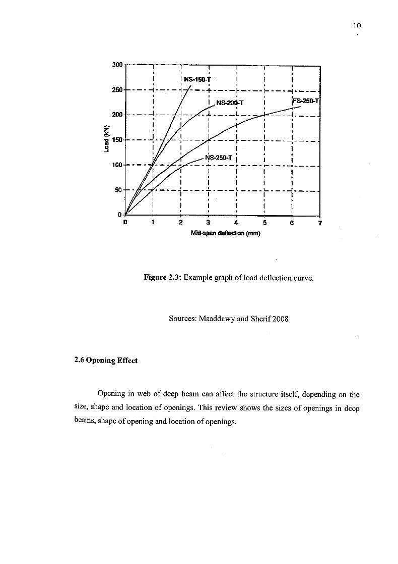
According to (Maaddawy and Sherif, 2008), that the beam behavior depended
primarily on the degree of interruption of the natural load path. As recorded in Figure
2.3, the beam without interrupting the load path exhibit almost a linear relationship up
to failure, which is the NS-1 50—T. Others beams, where the load path have been
interrupted by the opening plotted a non-linear graph. According to Benitez et al.,
(1998) again mentioned that when there has an opening of the beam, the strain
compatibility is reduced and there is loss of material to carrying the shear that is
effecting on the vertical deflection between the ends of the opening which is subjected
to the shear. This review shows that the opening of the beam is affecting the deflection
profile of the beam.
10
300I I I I I
INS..150-t I I I I I I I
250
200
Z
v150 cc 0 -J
100
50
00 1 2 3 4 5 6 7
MId-spn deflection (M, m)
Figure 2.3: Example graph of load deflection curve.
Sources: Maaddawy and Sherif 2008
2.6 Opening Effect
Opening in web of deep beam can affect the structure itself, depending on the
size, shape and location of openings. This review shows the sizes of openings in deep
beams, shape of opening and location of openings.

11
2.6.1 Size of Opening
As stated by Mansur, (2006), the openings that are circular, square, or nearly
square in shape may be considered as small openings provided that the depth (or
diameter) of the opening is in a realistic proportion to the beam size, about less than
40% of the overall beam depth. In such a case, beam action may be assumed to prevail.
Therefore, analysis and design of a beam with small openings may follow the similar
course of action as that of a solid beam. According (Maaddawy and Sherif, 2008) stated
the cracking load decreased as the opening size was increased. For size the opening in
this research, we applied three different sizes as follows 1 50x1 50 mm, 200x200 mm and
250x250 mm which corresponded to opening height-to-depth (a/h) ratios of 0.3, 0.4,
and 0.5, respectively. -
2.6.2 Shape of Opening
According to Alsaeq (2013) the use of circular opening has advantages over using
square opening regarding the structural strength of the beam. The circular opening was
hard to penetrate. The square openings were chosen because the sharp edges in square
openings that can easily crack and give a good data to the first objective which is
analyzing the crack pattern occur on the deep beams. It too can assist engineers in
practicing, when square opening is required in construction.
2.6.3 Location of Opening
Location of the opening can give different impact based on the location. When the
Opening is reasonably away from the load path, the compression force transfer takes the
Shortest route from the loading point to the closest support which resembles well to that
of the beam without an opening (Guan and Doh, 2007). The strength of the beam increases when the opening is located away from natural load path (Kong, 1978).
Location of Opening offers a good indication of the ultimate load-carrying capacity of

12
the beam which is affected by the size and location at which the natural load path is
interrupted by an opening (Guan and Doh, 2007). When the opening is located at the
mid-depth of the beam, the ultimate load-carrying capacity of the beam is very much
affected by the vertical location of the Opening (Guan and Doh, 2007). For this research,
the location of opening at the top of shear span near to the point load. The location of
the opening was to interrupt the natural load path that is the line connecting the bearing
plates at the loading and support points. It was also dependent on the extent of the
interruption of the load path from the opening.

CHAPTER 3
METHODOLOGY
3.1 Introduction
This chapter explains about the researches that was conducted and explain the
study that was carried out. In this chapter also included the explanations about the
materials utilized, the research, planning and also the testing have been carried out to
find the characteristic of openings concrete deep beams. This section also gives the
clear detail of sentiment around the research and clearly demonstrates how the objective
of this research can be achieved. At the early stage, the data and the literature review
were collected from the previous study.
The source of the study such as books, journals, magazine, research papers,
articles, symposium papers and internet. The discussion can be used to improve and
gain the knowledge and information regarding the scope of the research. For this study,
the materials used are Portland cement, coarse aggregate, and fine aggregate to deep
beams with a variety of square openings located at top of shear span near to the point
load. After casting and curing part done, the specimens tested by using flexural test (4
Point test).

3.2 Flow Chart
14
Prepare 4 beams formwork (100 X 500 X 1200)mm
1 Solid beam with no opening 3 Deep beams with opening
(150x150, 200x200, 250x250)mm
Reinforcement preparation for the solid control deep beam and deep
beams with openings
I Material preparation I
Beam Casting
Curing for 28 days
Testing
(4 Point test Flexural Test)
I Analysis and Discussion I
Figure 3.1: Research experimental work flow


