Permeability of rapid prototyped
artificial bone scaffold structures
Marcin Lipowiecki,1,2
Marketa Ryvolova, 1,2,3
Akos Tott€ osi,€
1,2 Niels Kolmer,
1,2 Sumsun Naher,
1 ,2, 4
Stephen A. Brennan,5 Mercedes Vazquez,
1,2,6 Dermot Brabazon
1 ,2, 6
1School of Mechanical and Manufacturing Engineering, Dublin City University, Glasnevin, Dublin 9, Ireland 2Advanced Processing Technology Research Centre, Dublin City University, Dublin 9, Ireland 3Department of Chemistry, Faculty of Science, Masaryk University, Kotl a rska 2, Brno, Czech Republic 4School of Engineering and Mathematical Sciences, City University London, London, United Kingdom 5Department of Orthopaedic Surgery, University College Hospital Galway, Galway, Ireland 6Irish Separation Science Cluster (ISSC), National Centre for Sensor Research, Dublin City University, Dublin 9, Ireland
Abstract
In this work, various three-dimensional (3D) scaffolds were produced via micro-
stereolithography (m-SLA) and 3D printing (3DP) techniques. This work demonstrates the
advantages and disadvantages of these two different rapid prototyping methods for
production of bone scaffolds. Compared to 3DP, SLA provides for smaller feature production
with better dimensional resolution and accuracy. The permeability of these structures was
evaluated experimentally and via numerical simulation utilizing a newly derived Kozeny–
Carman based equation for intrinsic permeability. Both experimental and simulation studies
took account of porosity percentage, pore size, and pore geometry. Porosity content was
varied from 30% to 70%, pore size from 0.34 mm to 3 mm, and pore geometries of cubic and
hexagonal closed packed were examined. Two different fluid viscosity levels of 1 mPas and
3.6 mPas were used. The experimental and theoretical results indicated that permeability
increased when larger pore size, increased fluid viscosity, and higher percentage porosity
were utilized, with highest to lowest degree of significance following the same order. Higher
viscosity was found to result in permeabilities 2.2 to 3.3 times higher than for water. This
latter result was found to be independent of pore morphology type. As well as demonstrating
method for determining design parameters most beneficial for scaffold structure design, the
results also illustrate how the variations in patient’s blood viscosity can be extremely
important in allowing for permeability through the bone and scaffold structures.
Key Words: permeability, synthetic scaffold, tissue engineering,trabecular bone, rapid
prototyping
INTRODUCTION
Synthetic bone scaffolds are used during surgery to aid fracture repair, replace diminished
bone stock, and assist osseointegration of orthopedic implants to the native bone. These
structures need to meet mechanical strength and permeability requirements to allow for load
bearing and osteoconductivity. To increase osteoconductivity, the structure should be
designed to allow for flow of nutrients and waste products related to the growth of new tissue.
Fluid flow through a bone scaffold is therefore an important factor in its ability to regenerate
a living tissue. Permeability is often used as a measure of a structure’s ability to allow for
this. There is currently a wide range of biocompatible materials available for tissue

engineering including polymers, ceramics and metals.1–4
Porous tantalum (Trabecular
MetalTM
) was characterized in the work of Shimko et al.2,3
In their work,scaffolds with a
porosity of 66% to 88% were tested for various parameters such as tangent elastic modulus,
yield stress, strain behavior, and intrinsic permeability.
They concluded that the intrinsic permeability and tangent elastic modulus of tantalum
correspond well with those of cancellous bones of similar porosity. Whereas ceramic and
metal based scaffold materials are used for hard tissue scaffolds, polymer based scaffolds are
used for either hard or soft tissue applications depending on the polymer type used and
implant site specific requirements. Polymer-based scaffolds types were reviewed recently.1,5
The use of poly(methyl methacrylate) in particular has been found to be suitable for the
manufacturing of highly porous scaffolds with controllable elastic modulus and
permeability.2
Scaffolds developed by foaming sol–gel derived bioactive glasses were
characterized by Jones et al.6
In their work the interconnectivity of pores was assessed and it
was found that the permeability of the fabricated scaffolds was comparable to that of
trabecular bone.
The scaffold microstructure plays an important role in cell attachment and tissue
vascularization.7
It is well known that cell ongrowth is highly dependent on the nutrients and
waste product transfer through the porous structure.8,9
Therefore, measurement of the
capability of fluid to travel through the fabricated scaffold designs is an important scaffold
structure characteristic. Permeability of the structure is thought to be related more to cell
growth than conventionally analyzed parameters alone, for example, porosity and pore size.7
Permeability is typically measured as water flow rate through the scaffold encased into a
sealed chamber under a known hydrostatic pressure.10
Al-Munajjed et al.,11
investigated the permeability and the porosity of hyaluronan–collagen
scaffolds, suitable for soft tissues. Numerical calculations confirmed experimental results
which indicated that porosity and permeability increased with increasing pore sizes. In their
work, the three pore sizes chosen were 303, 403, and 525 mm. The test fluid media was water
which was stored in a tank set at a constant height above the test specimen in order to keep
the hydrostatic pressure at the top of the test sample constant. To determine the permeability
constant, m, Darcy’s law was used as follows:
where Q is the volume of discharge, l is the length of sample which the fluid flows through, h
is the hydrostatic pressure, d is the sample total cross-sectional area, and t is the time taken
for the fluid to flow through. A more commonly used alternative measure of fluidity through
scaffolds is called intrinsic permeability K (in units of m2) and can be calculated from
Darcy’s law as follows:
where q is the volumetric flow rate, l is the fluid viscosity, p is the pressure difference across
the sample, and d and l are as per Eq. (1).12,13
Permeability of bones
Several experimental studies have been conducted to measure the intrinsic permeability of
real bone.8,14,15
In the work of Kohles et al.,15
permeability values ranging between 10210
m2
and 1029
m2
in various directions though bovine distal femur were determined using water as
the fluid medium. These bovine samples produced values in a range similar to that of human
bone. Grimm and Williams measured permeabilities for human calcaneal trabecular bone in
the range 0.40 x 10⁻⁹
m2
to 11 x 10-9
m2
using raw linseed oil as the fluid medium.8
Permeability values determined in previous investigations for various types of human bone
have ranged from 10-11
m2
to 10-8
m2.1
Different flow rates have been observed to occur at the different scale levels within
trabecular bone structures which include intra- and intertrabecular pores. Various pore types
include lacunar–canalicular pores (on the order of 0.1 mm), vascular channels (on the scale of
20 mm), and openpore marrow space (up to 1 mm in scale). Estimation of bone permeability
just through the lacunar–canalicular pores was investigated in the work of Beno et al.14
In
their work, several parallel-fibered diaphysis bone samples were used, from chick, rabbit,
bovine, horse, dog and human origin. The number of canaliculi emanating from an osteocyte
lacuna was determined and the local intrinsic permeability was estimated, using
microstructural measurements. The authors provided measurements of intrinsic permeability
along three axes, proving that these bone samples were anisotropic, as has previously been
found for bovine bone by other workers.15
It was also shown that that the permeability was
very sensitive to canalicular and osteocytic dimensions, less sensitive to the fiber matrix
spacing and strongly dependent on the type of animal tissue being studied.14 , 15
The effect of cyclical mechanical loading on fluid flow rate has been investigated using an
ex vivo ovine model.16
The fluid flow, which was monitored via applied color tracers, showed
that mechanical load enhanced the molecular transport and that diffusion alone could
efficiently transport small (300–400 Da) but not larger molecules. Previous work has also
shown that cyclical loading of human bone structures can affect blood content and, in turn,
bone shear strength.17
Permeability can be seen as important therefore not only for
osteoconductivity but also for the strength of bone structures.
Mathematical calculation and experimental determination of intrinsic permeability based
on the tetrakaidecahedral unit has been previously presented.18 , 19
Permeability was found,
both experimentally and mathematically, to increase with increased pore size, and porosity. A
similar technique was used in the work of Malachanne et al.20
The aim of their work was to
compare the intrinsic permeability determined by experimental measurement with their
developed finite element model. The experimental measurements for validation in their work
were recorded with ex vivo ox bone. The experimental setup consisted of a standing pipe with
storage water held at a set height above the test sample producing a constant hydrostatic

pressure. The time for a defined volume of water to pass through the sample was measured.
An intrinsic permeability of K = 1.1 3 10-2
m2
was determined.20
Swider et al.21
used magnetic
resonance imaging to determine the fluid flow velocity, distribution, and permeability in a
porous material. Their investigation was focused on hydroxyapatite bone scaffolds and the
intrinsic permeability coefficient was calculated using Darcy’s law, resulting in a value of K
= 2.66 3 10-2
m2.
Fabrication and permeability testing methods for artificial scaffolds
Although some works indicate that simulating natural healthy bone geometry is best for
scaffold structures, others indicate that larger pore sizes are preferable within the structure to
allow for ingrowth of native bone and for enhanced fluid transport during the short to
medium term healing process after implantation.
Fluids used for this type of analysis often differ between various research groups. Usually
water solutions are used3; however, gases have also been examined. For example, in the work
of Chor and Li7
dry air was used as the fluid medium to avoid scaffold hydrolysis and pore
blockage.
Despite this previous work, the optimal method of testing, fabrication method, and pore
geometry is still undecided. In order to advance the knowledge in this area, the work
presented in this article was undertaken using two different well defined structure types, cubic
and hexagonal close packed. These were fabricated by stereolithography (SLA) and three-
dimensional (3D) printing (3DP). A great amount of interest within the last 10 years has
focused on the use of rapid prototyping to manufacture synthetic bone scaffolds.23–25
Structures produced by rapid prototyping techniques, allow for control of pore size, porosity,
and geometry. These structures have previously been tested by the authors and confirmed to
be suitable to withstand the mechanical loading requirements of bone scaffolds.26 , 27
These
structure types provide a high stiffness and, at the same time, a high level of porosity and
large pore size which would be considered advantageous for achieving a high level of
permeability. The aim of this work therefore was to investigate the use of SLA and 3DP rapid
prototyping methods for the production of predefined, previously stresstested, cubic, and
hexagonal synthetic bone scaffold designs with a view to optimizing these for permeability.
MATERIALS AND METHODS
Experimental permeability testing
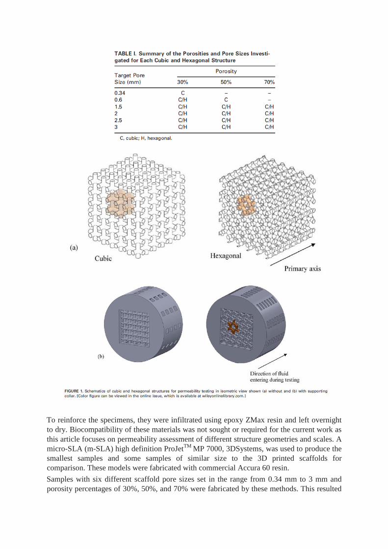
The scaffold model structures were designed using computer aided design software
SolidEdge V100 and saved as SLA files. Two basic structures, hexagonal and cubic, were
fabricated, see Figure 1. The set pore size and porosity percentage are summarized in Table I.
The cubic structure was omnidirectional and therefore was tested along only one axis. The
hexagonal structure has one primary axis in which fluid can flow with least obstruction
(shown in Fig. 1). The fluid flow tests were performed along this direction. The majority of
samples were manufactured using a Z310 ZCorp 3D printer with standard 3DP plaster
powder material ZP113 and binder ZB-58.
To reinforce the specimens, they were infiltrated using epoxy ZMax resin and left overnight
to dry. Biocompatibility of these materials was not sought or required for the current work as
this article focuses on permeability assessment of different structure geometries and scales. A
micro-SLA (m-SLA) high definition ProJetTM
MP 7000, 3DSystems, was used to produce the
smallest samples and some samples of similar size to the 3D printed scaffolds for
comparison. These models were fabricated with commercial Accura 60 resin.
Samples with six different scaffold pore sizes set in the range from 0.34 mm to 3 mm and
porosity percentages of 30%, 50%, and 70% were fabricated by these methods. This resulted

in 15 different cubic and 13 different hexagonal scaffold pore size/percentage combinations
being fabricated, see Table I. Triplicates of each sample type were fabricated and flow rate
through each sample was measured three times in order to allow for repeatability analysis.
This resulted in nine flow rate measurements for each of the scaffold geometries. In this work
the model pore size was defined as the inner length of the edges of the cubes for the cubic
structures, and as the minimum diameter of an inner circle which could be contained within
the hexagonal structures. For the hexagonal structures, the height of the repeated units was
also recorded in order to fully define these lattice structures. The boundary of the scaffold
structures was a 15 mm 3 15 mm 3 15 mm for pore sizes from 1.5 mm to 3.0 mm and a 3 mm
3 3 mm 3 3 mm for pore sizes from 0.34 mm to 0.60 mm. A solid outer shell was built into
the model to house these scaffold structures and to fit into the clamping device for
permeability measurement, see Figure 1.
The permeability testing rig is shown in Figure 2. This cylindrical collar around the scaffold
structures served as a sealing surface with the clamping device walls. The printing time for 10
samples with a 3mm pore size was about 30 min and for 10 samples with a 1.5 mm pore size
the printing time was about 90 min.
Two liquids with different viscosities (water and water with 30% glycerol solution) were
tested. The water–glycerol solution (Sigma Aldrich) was used as a basic simulation of higher
viscosity blood fluid, the viscosity of which is in the range of three to six times higher than
water depending on the hematocrit, blood flow rate, and blood constituents such as proteins,
nutrients, hormones, and excretory products. Blood typically varies from 3 mPas to 6 mPas
while blood without cells typically varies from 1 mPas to 1.3 mPas.28,29
In this work, the
viscosity of the water and water–glycerol solution used were recorded using a rotational
viscometer (Rheology International Instrument, ASTM Spindle Type2) at 1 mPas and 3.6
mPas, respectively. In order to understand the influence of the sample material on the flow,
the contact angles of three different fluids, that is, tap water, deionized water, and water–
glycerol solution (30% glycerol by mass), were measured with a FTA-200 dynamic contact
angle analyzer.
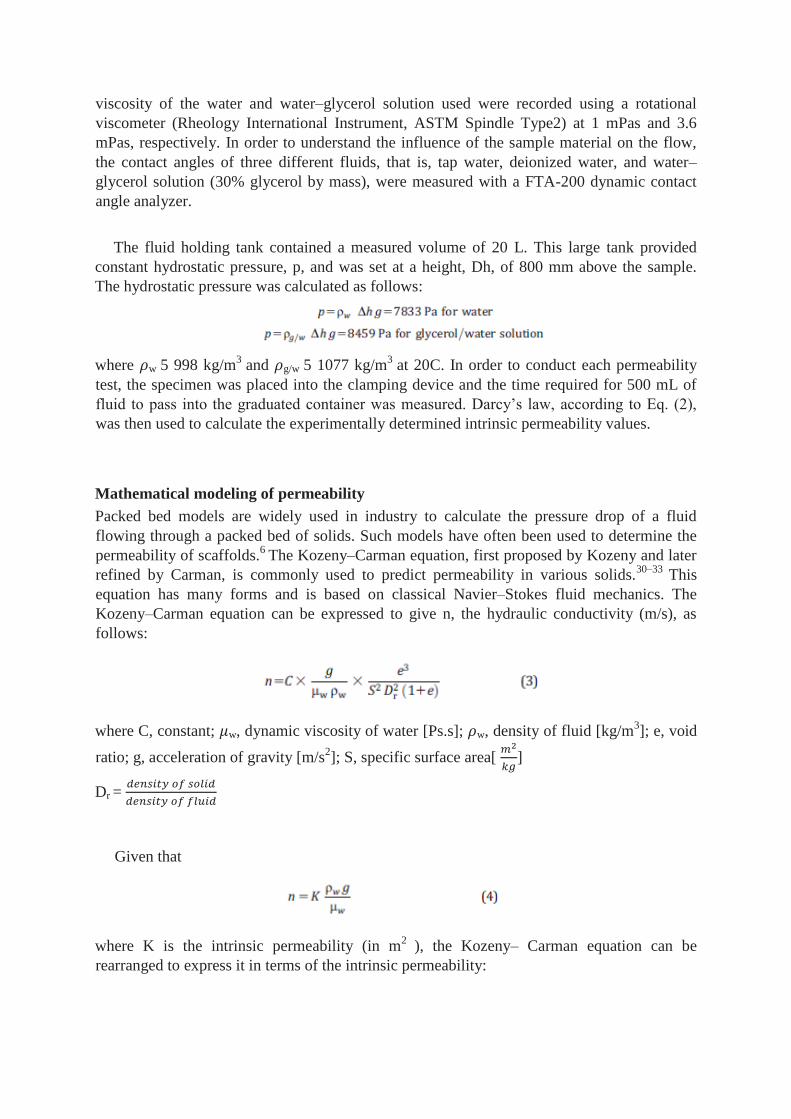
The fluid holding tank contained a measured volume of 20 L. This large tank provided
constant hydrostatic pressure, p, and was set at a height, Dh, of 800 mm above the sample.
The hydrostatic pressure was calculated as follows:
where w 5 998 kg/m3
and g/w 5 1077 kg/m3
at 20C. In order to conduct each permeability
test, the specimen was placed into the clamping device and the time required for 500 mL of
fluid to pass into the graduated container was measured. Darcy’s law, according to Eq. (2),
was then used to calculate the experimentally determined intrinsic permeability values.
Mathematical modeling of permeability
Packed bed models are widely used in industry to calculate the pressure drop of a fluid
flowing through a packed bed of solids. Such models have often been used to determine the
permeability of scaffolds.6
The Kozeny–Carman equation, first proposed by Kozeny and later
refined by Carman, is commonly used to predict permeability in various solids.30–33
This
equation has many forms and is based on classical Navier–Stokes fluid mechanics. The
Kozeny–Carman equation can be expressed to give n, the hydraulic conductivity (m/s), as
follows:
where C, constant; w, dynamic viscosity of water [Ps.s]; w, density of fluid [kg/m3]; e, void
ratio; g, acceleration of gravity [m/s2]; S, specific surface area[
]
Dr =
Given that
where K is the intrinsic permeability (in m2
), the Kozeny– Carman equation can be
rearranged to express it in terms of the intrinsic permeability:

we get for intrinsic permeability,
The constant, C, is used to take into account the morphology of the flow-through channels
in a porous media. A value of 0.2 based on previous work was used for C.30
The density of the
solid was 1.21 kg/m3
for the SLA models and 1.25 kg/m3
for the 3DP models. The specific
surface area, S, which varied with each scaffold design is one of the most critical parameters
in this equation. The solid specific surface area of the structures as measured directly from
corresponding CAD files was used in these calculations.
RESULTS AND DISCUSSION
Fabricated scaffold structure dimensions were generally found to be slightly larger in size for
the SLA produced scaffolds and smaller for the 3DP produced scaffolds compared to the
original CAD file dimensions. The resulting scaffold pore sizes are shown with
corresponding permeability results in Figures 3 and 4. For the experimental work, the shortest
and longest periods recorded for the fluid sample to flow though the scaffold were 3.02 s and
98.22 s, respectively. The shortest time recorded was for the SLA material, with water as
fluid, the hexagonal structure, with a 1.60 mm pore size, and with 70% structural porosity.
The longest time was recorded from the glycerol–water solution flowing through the SLA
material with the smallest pore size of 0.53 mm, 30% porosity, and a cubic structure.
Experimental permeability testing results
Figure 3(a,b) shows the experimentally captured permeability results with water as the fluid
medium for the cubic and hexagonal structures, respectively. Figure 4(a,b) shows the
experimental measured permeability results with the glycerol–water solution for cubic and
hexagonal structures, respectively. The range of permeabilities measured was from 1.84 x10-
10 m
2 to 4.19 x 10
-9 m
2. These measurements were highly repeatable, with 95% confidence
intervals being an order of magnitude less than the measured results. Thus, the plotted error
bars were actually overlapped by the point markers in Figures 3 and 4. As expected, higher
flow rates and permeabilities occurred through structures with increased porosity and pore
size.

Within the range of pore sizes and porosities measured, pore size had a larger effect on the
permeability results than the porosity level. Comparing similar sample types, experimentally
measured permeability values were in the range of 2.2 to 3.3 times higher for the glycerol–
water solution compared to the less viscous water. This could be attributed to higher flow
path disorder of the lower viscosity fluid flow through the structures.

This range was independent of structure type (hexagonal or cubic). This could be attributed to
the higher contact angles with the scaffolds and associated increased hydrophobicity for the
more viscous fluid, see Table II rows 1 and 3. Table II presents the contact angles determined
with the different scaffold materials and fluids. Contact angles for the m-SLA scaffolds
(Accura 60 material) were approximately six times higher, compared to the 3DP scaffolds,
indicating their greater degree of hydrophobicity which resulted in higher permeability
through the m-SLA scaffolds compared to the 3 DP scaffolds for similar pore size and
porosity levels, see Figures 3 and 4. An in-depth review of methods for the evaluation of
tissue engineering scaffold permeability has recently been presented.34
Mathematical modeling of permeability results
Figure 5 shows the computed permeability for the cubic and hexagonal structures as
calculated using Eq. (5). This formulation of intrinsic permeability derived from the Kozeny–
Carman equation is mostly dependent on the solid structural properties, that is, density,
specific surface area, and porosity.
Fluid densities cancel out and so the results in Figure 5 are independent of fluid type. The
calculated permeabilities for the cubic and hexagonal structures ranged from 2.33 3 10211
m2
to 4.15 3 1029
m2, which encompasses the range of permeabilities measured experimentally.
Similar trends in data with pore size and percentage porosity were noted, compared to the
measured results. The calculated permeabilities for the cubic structures were 1.1 to 3.8 times
higher than for the hexagonal structures. In comparison, the experimental measured
permeability values indicated less preference for structure type. Comparing similar sample
types, values for the hexagonal structures were in the range of 0.5 to 1.2 times those
determined for the cubic structures. This range determined was independent of fluid. The
results in Figure 5, and highlighted in Table III, show that the lowest levels of theoretically
calculated permeability, which were produced at the lowest pore sizes, were lower than those
measured during the experimental work.
This indicates that while Eq. (5) gives a good indication of relative trends between different
structures, in order to obtain absolute values which agree more closely with experimental
data, the intrinsic formulation should take into account other factors such as pressure drop of
fluid across the sample, fluid viscosity and surface energy at the fluid/ scaffold interface.
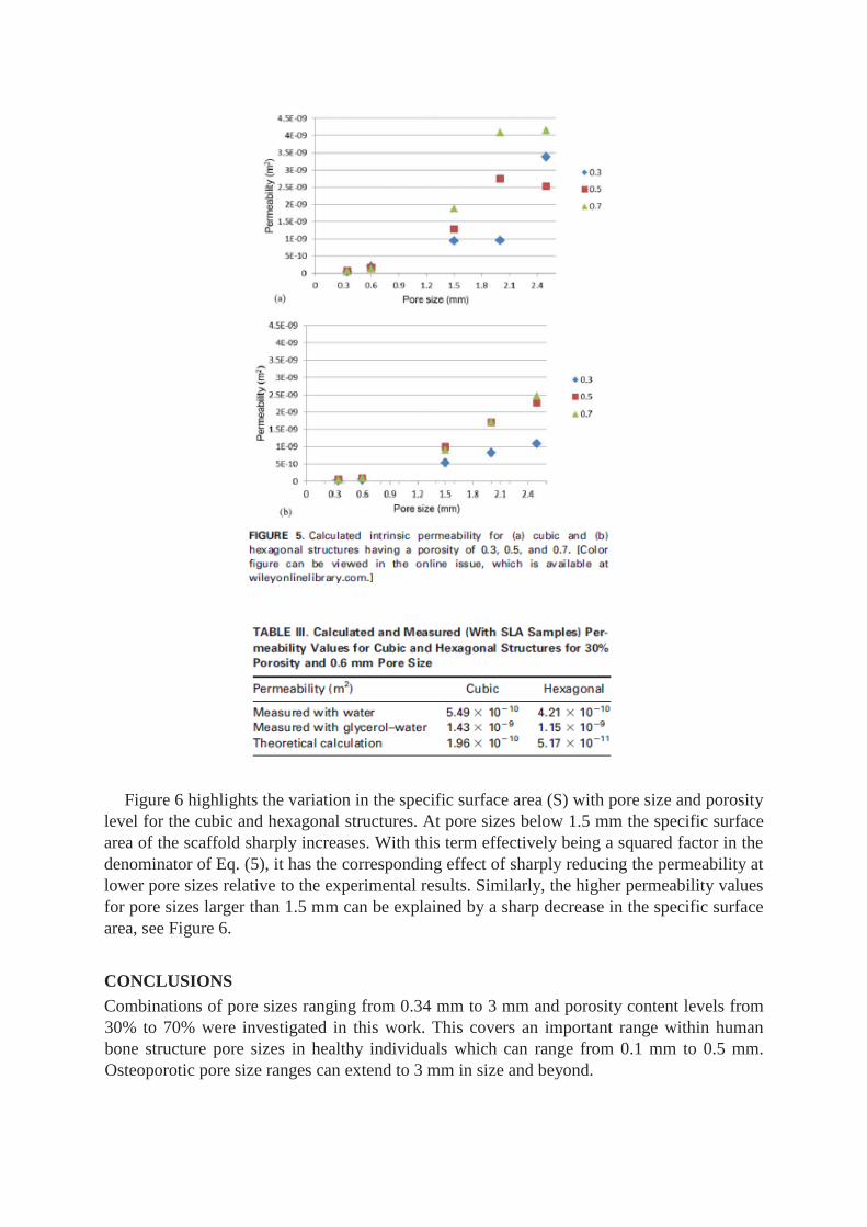
Figure 6 highlights the variation in the specific surface area (S) with pore size and porosity
level for the cubic and hexagonal structures. At pore sizes below 1.5 mm the specific surface
area of the scaffold sharply increases. With this term effectively being a squared factor in the
denominator of Eq. (5), it has the corresponding effect of sharply reducing the permeability at
lower pore sizes relative to the experimental results. Similarly, the higher permeability values
for pore sizes larger than 1.5 mm can be explained by a sharp decrease in the specific surface
area, see Figure 6.
CONCLUSIONS
Combinations of pore sizes ranging from 0.34 mm to 3 mm and porosity content levels from
30% to 70% were investigated in this work. This covers an important range within human
bone structure pore sizes in healthy individuals which can range from 0.1 mm to 0.5 mm.
Osteoporotic pore size ranges can extend to 3 mm in size and beyond.


The resulting range of permeabilities measured was from 1.84 3 10210 m2 to 4.19 3 1029 m2,
which is similar to the range reported in previous studies for analogue and human tissue
structures, see Tables IV and V. All experimental results were determined to be highly
repeatable. As expected, higher flow rates and permeabilities were recorded for larger
porosity content levels and pore sizes.
This follows also from the theoretical calculations where increased pore size provided a
decrease in specific surface area which in turn results in increased permeability, see Eq. (5).
The experimental permeability measurements from water–glycerol were 2.2 to 3.3 times
higher than for water. This range was the same for both structure morphologies, cubic and
hexagonal. This difference in permeabilities can be attributed to the different surface energies
at the fluid/scaffold interface. Contact angles for m-SLA scaffold material were in the range
of five to seven times those of the 3 DP scaffold materials. Higher hydrophobicity of the m-
SLA scaffold material could therefore be expected to result in increased permeability. From
Eq. (2), formulation for intrinsic permeability, increased viscosity of the water–glycerol
solution can also be seen to result in increased permeability.
The theoretical calculated permeability through the cubic structures was determined to be
1.1 to 3.8 times higher compared to that through the hexagonal structures. However, the
experimental results showed no determinable effect on permeability, for either fluid, of pore
morphology between the cubic and hexagonal structures. This discrepancy between
experiment and theory could be partly due to an insufficient number of lattice cells having
been tested during the experimental work. The theoretical calculation however using Eq. (5)
does not take into account pressure drop of fluid across the sample, fluid viscosity, or surface
energy at the fluid/scaffold interface. While Eq. (5) provides more comprehensive analysis of
the effect of scaffold structure on permeability, Eq. (2) accounts for some of these latter
mentioned parameters. A new model therefore combining the benefits of these two equations
is suggested from this work in order to determine absolute permeability values.
The predominant factor experimentally and theoretically affecting permeability values was
the pore size. Viscosity was found to be the next most influential factor followed by level of
porosity. Increased pore size, viscosity, and porosity resulted in the highest permeability
values. The work presented in this article indicates that the fluid viscosity and corresponding
surface energy at the fluid–solid interface have a significant influence on permeability.
Specifically, higher viscosity and surface energy, within the bounds of the values examined in
this study, resulted in significantly higher permeability values. Structure morphology along
the primary axis, in terms of the cubic and hexagonal structures evaluated, were not found to
have a significant effect on permeability.
When designing bone scaffolds for use during orthopedic surgery, biocompatibility and an
ability to withstand the local loading requirements are primary initial considerations. For
longer term success of the implant, good permeability of the scaffold is critical to allow for
inflow of cells and nutrients, as well as for waste product transfer. The results of this article
show that in order to achieve good permeability, the pore size, porosity level, and material
surface energy are primary design parameters that must be controlled. From the clinical
viewpoint, the results presented here also illustrate how the variations in patient’s blood
viscosity can be extremely important in allowing for permeability through the bone and
scaffold structures. Careful consideration and further research should therefore focus on the
effects on viscosity of the use of procoagulopathic agents or even the short term
administration of anticoagulants such as heparin in an effort to aid patency of these channels.
REFERENCES
1. Cheung HY, Lau KT, Lu TP, Hui D. A critical review on polymerbased bio-engineered
materials for scaffold development. Compos Part B: Eng 2007;38:291–300.
2. Shimko DA, Nauman EA. Development and characterization of a porous poly(methyl
methacrylate) scaffold with controllable modulus and permeability. J Biomed Mater Res
Part B: Appl Biomater 2007;80B:360–369.
3. Shimko DA, Shimko VF, Sander EA, Dickson KF, Nauman EA.
Effect of porosity on the fluid flow characteristics and mechanical properties of tantalum
scaffolds. J Biomed Mater Res Part B: Appl Biomater 2005;73B:315–324.
4. Ochoa I, Sanz-Herrera JA, Garcia-Aznar JM, Doblare M, Yunos DM, Boccaccini AR.
Permeability evaluation of 45S5 Bioglassbased scaffolds for bone tissue engineering. J
Biomech 2009;42: 257–260.
5. Dhandayuthapani B, Yoshida Y, Maekawa T, Kumar D. Polymeric Scaffolds in Tissue
Engineering Application: A Review. Int J Polym Sci 2011;2011:19.
doi:10.1155/2011/290602.
6. Jones JR, Poologasundarampillai G, Atwood RC, Bernard D, Lee PD. Non-destructive
quantitative 3D analysis for the optimisation of tissue scaffolds. Biomaterials
2007;28:1404–1413.
7. Chor MV, Li W. A permeability measurement system for tissue engineering scaffolds.
Meas Sci Technol 2007;18:208–216.
8. Grimm MJ, Williams JL. Measurements of permeability in human calcaneal trabecular
bone. J Biomech 1997;30:743–745.
9. Botchwey EA, Dupree MA, Pollack SR, Levine EM, Laurencin CT. Tissue engineered
bone: measurement of nutrient transport in three-dimensional matrices. J Biomed Mater
Res Part A 2003;67A: 357–367.
10. Agrawal CM, McKinney JS, Lanctot D, Athanasiou KA. Effects of fluid flow on the in
vitro degradation kinetics of biodegradable scaffolds for tissue engineering. Biomaterials
2000;21:2443–2452.
11. Al-Munajjed AA, Hien M, Kujat R, Gleeson JP, Hammer J. Influence of pore size on
tensile strength, permeability and porosity of hyaluronan-collagen scaffolds. J Mater Sci:
Mater Med 2008;19: 2859–2864.
12. Karande TS, Ong JL, Agrawal CM. Diffusion in musculoskeletal tissue engineering
scaffolds: design issues related to porosity, permeability, architecture, and nutrient mixing.
Ann Biomed Eng 2004;32:1728–1743.
13. Li SH, de Wijn JR, Li JP, Layrolle P, de Groot K. Macroporous Biphasic Calcium
Phosphate Scaffold with High Permeability/ Porosity Ratio. Tissue Eng 2003;9:535–548.
14. Beno T, Yoon YJ, Cowin SC, Fritton SP. Estimation of bone permeability using accurate
microstructural measurements. J Biomech 2006;39:2378–2387.
15. Kohles SS, Roberts JB, Upton ML, Wilson CG, Bonassar LJ, Schlichting AL. Direct
perfusion measurements of cancellous bone anisotropic permeability. J Biomech
2001;34:1197–1202.
16. Knothe Tate ML, Knothe U. An ex vivo model to study transport processes and fluid flow
in loaded bone. J Biomech 2000;33:247 – 254.
17. Brennan S, Brabazon D, O’Byrne J. Effect of vibration on the shear strength of impacted
bone graft in revision hip surgery. J Bone Joint Surg 2011;93B:755–759.

18. O’Brien F, Harley B, Waller M, Yannas I, Gibson L, Prendergast P. The effect of pore size
on permeability and cell attachment in collagen scaffolds for tissue engineering. Technol
Health Care 2007 ; 15:3–17.
19. Gibson LJ, Ashby MF. Cellular Solids: Structure and Properties. Cambridge: Cambridge
University Press; 1999.
20. Malachanne E, Dureisseix D, Canadas P, Jourdan F. Experimental and numerical
identification of cortical bone permeability. J Biomech 2008;41:721–725.
21. Swider P, Conroy M, Pedrono A, Ambard D, Mantell S, Sballe K, Bechtold JE. Use of
high-resolution MRI for investigation of fluid flow and global permeability in a material
with interconnected porosity. J Biomech 2007;40:2112–2118.
22. Haugen H, Will J, Kohler A, Hopfner U, Aigner J, Wintermantel E. Ceramic TiO2-foams:
characterisation of a potential scaffold. J Eur Ceram Soc 2004;24:661–668.
23. Eosoly S, Brabazon D, Lohfeld S, Looney L. Selective laser sintering of Eosoly S,
Brabazon D, Lohfeld S, Looney L. Selective laser sintering of hydroxyapatite/poly-E-
caprolactone scaffolds. Acta Biomater 2010;6:2511–2517.
24. Eosoly S, Lohfeld S, Brabazon D. Effect of hydroxyapatite on biodegradable scaffolds
fabricated by SLS. Key Eng Mater 2009;396398:659–662.
25. Szucs T, Brabazon D. Effect of saturation and post processing on 3D printed calcium
phosphate scaffolds. Key Eng Mater 2009;396398:663–666.
26. Lipowiecki M, Ryvolova M, Tottosi A, Naher S, Brabazon D. Permeability of rapid
prototyped artificial bone scaffold structures. Adv Mater Sci Res 445;2012:607–612.
27. Lipowiecki M, Brabazon D. Design of bone scaffolds structures for rapid prototyping with
increased strength and osteoconductivity. Adv Mater Res 2010;83-86:914–922.
28. Rosenson RS, McCormick A, Uretz EF. Distribution of blood viscosity values and
biochemical correlates in healthy adults. Clin Chem 1996;42:1189–1195.
29. Lowe GD, Drummond MM, Lorimer AR, Hutton I, Forbes CD, Prentie CR, Barbenel JC.
Relation between extent of coronary artery disease and blood viscosity. Br Med J
1980;280:673.
30. Chapuis RP, Aubertin M. Technical Report EPM-RT-2003 03, Ecole Polytechnique,
Montreal, Quebec; 2003.
31. Steiakakis E, Gamvroudis C, Alevizos G. Kozeny–Carman equation and hydraulic
conductivity of compacted clayey soils. Geomaterials 2012;2:37–41.
32. Syahroma A, Kadirb MRA, Abdullahc J, Ochsnera€
A. Permeability studies of artificial
and natural cancellous bone structures. Med Eng Phys 2013;35:792–799.
33. Truscello S, Kerckhofs G, Van Bael S, Pyka G, Schrooten J, Van Oosterwyck H.
Prediction of permeability of regular scaffolds for skeletal tissue engineering: A combined
computational and experimental study. Acta Biomater 2012;8:1648–1658.
34. Pennella F, Cerino G, Massai D, Gallo D, Labate GF, Schiavi A, Deriu MA, Audenino A,
Morbiducci U. A survey of methods for the evaluation of tissue engineering scaffold
permeability. Ann Biomed Eng 2013;4:2027–2041.
35. Wu YC, Lee TM, Chiu KH, Shaw SY, Yang CY. A comparative study of the physical and
mechanical properties of three natural corals based on the criteria for bone-tissue
engineering scaffolds. J Mater Sci: Mater Med 2009;20:1273–1280.
36. Tierney CM, Haugh MG, Liedl J, Mulcahy F, Hayes B, O’Brien FJ. The effects of
collagen concentration and crosslink density on the biological, structural and mechanical

properties of collagen-GAG scaffolds for bone tissue engineering. J Mech Behav Biomed
Mater 2009;2:202–209.
37. Sanz-Herrera JA, Kasper C, van Griensven M, Garcia-Aznar JM, Ochoa I, Doblare M.
Mechanical and flow characterization of Sponceram carriers: Evaluation by
homogenization theory and experimental validation. J Biomed Mater Res Part B: Appl
Biomater 2008;87B:42–48.


