
Camper Van
Manufactured in the U.K. by Northern Leisure Group Ltd. T/A Kiddy Rides. 4 Kingsmark Court, Intercity Way, Leeds LS13 4PN, United Kingdom
Serial No. Born On:
Operators Handbook
Peppa Pig Astley Baker Davies Ltd/Entertainment One UK Ltd 2003cB
RD
S
S
www.kiddyrides.uk.com
CONTENTS
Introduction
Safety Matters
Initial Inspection
Initial Operation
Siting Your Ride
Daily Checks
Taking Care Of Your Ride
Standard Operation & AdjustmentsControl Box / TimerRide TimeVolume SettingsPrice Of PlaySwitch Settings
Inspection HatchesInspection & maintenance of components
Coin MechanismCleaningInstallation and Removal
Fault Finding
Contact ProceduresOrdersSpares RepairsHours of Business
Ride History / Log
Your Notes
Declaration Of Conformity
Composite Data Sheet
1
2
3
3
4
5
6
7
10
13
21
22
23,24
25,26
8
9
Wiring Schematics
Wiring Loom Reference
Plugs & Connections
Base Loom
Base Mechanism Components
Parts List
Removal Of Bodyshell
12
14
15
16
17,18,19
20
Video Feature 11
27,28
29,30

INTRODUCTION
Thank you for purchasing your new children’s coin operated ride from Northern Leisure Group Ltd. / Kiddy Rides! We trust it will give you many years of profitable
service!
Established in 1986, the Northern Leisure Group of companies is the UK’s leading independent operator, dealer, manufacturer, and distributor of children’s coin operated rides. Our extensive experience in a wide range of electronic entertainment products has allowed us to offer the ultimate in choice, safety and quality. Complete customer satisfaction is what motivates us. Being independent allows us to nurture this goal – ultimately giving thousands of children and parents world-wide, the assurance that they are in a safe, clean, and fun environment. Kiddy Rides supplies a wide range of children’s rides for sale, income share, or on a fixed rental basis. As well as supplying the rides, it is responsible for unbeatable after-sales support and service for all Kiddy Rides customers as well as other operators. Our equipment has been manufactured to the highest standard of construction and safety in order to conform to the H.S.E. Fairground and Amusement Parks, A Code of Safe Practice and the U.K. Health and Safety at Work Act 1974. All our rides have undergone thorough examinations, and come with a 12 months ADIPS certification of conformity. The guidance in this manual is relevant to the safe operation of children’s rides wherever they may be operated.
NORTHERN LEISURE GROUP LTD. UNIT 4 KINGSMARK COURT
INTERCITY WAY SWINNOW
LEEDS LS13 4PN
UNITED KINGDOM
TEL: +44 (0) 113 239 38 03 FAX: +44 (0) 113 236 31 94 Email: [email protected]
www.kiddyrides.co.uk
1

Northern Leisure/Kiddy Rides is a registered Inspection Body of ADIPS (the Amusement Device Inspection Procedure Scheme), conducting independent examinations and certification of children’s coin operated rides in accordance with guidance published by the Health and Safety Executive (HSE). By independent, we mean we are not linked to any particular manufacturer and will apply the guidance with equal diligence, regardless of the type of ride, or it’s manufacturer. Remember, our aim is to help you comply with the HSE guidelines. Because of the young age of those who enjoy coin operated children’s rides (kiddie rides), safety should be of paramount importance to operators. There is surely a moral duty to safeguard the children that use our industry’s products. Safety doesn’t just happen however, it requires commitment from manufacturers, operators and inspectors to ensure high standards. As an operator it is your duty to make yourself aware of safety requirements, especially as failure to comply can lead to injury to children, and furthermore, prosecution. By adopting a few simple procedures and having annual safety checks performed on your rides, you can show yourself to be conforming with HSE and Local Authority guidelines. Also you will gain peace of mind knowing that you have taken active steps to minimize the risks to young children who use your rides. It is not always easy to find out exactly what is required of an operator. However there are strict guidelines laid down by BACTA (British Amusement and Catering Trade Association) entitled Kiddie Rides; A Safety Guide. It is produced by a committee of BACTA members, some of whom represent manufacturers of kiddie rides themselves. The guide is fully endorsed by the HSE. In an attempt to highlight the importance of safety within the industry, ADIPS has been integrated into the BACTA guidelines. This initiative sets out procedures which must be observed by registered Inspection Bodies. Furthermore, ADIPS is unified with the HSE Fairground and Amusement Parks Code of Safe Practice. To comply with this, a ride must undergo a thorough examination, and documentation must be issued, be retained, and be available for inspection by the Health and Safety Inspectorate and/or an officer of the Environmental Health Department of the local authority. Thorough examinations must be carried out at least every fourteen months (annual examinations are recommended). Certification of rides by approved inspectors will give responsible operators within our industry the credibility they deserve. An ADIPS certificate is a badge of excellence, ensuring you have taken all the necessary steps to ensure danger risks are kept to a minimum. In the past, inspections of children’s rides by the HSE appeared to be taking place in response to safety related incidents. However, this is changing rapidly, and it would appear random tests are under way. Inspectors requesting ADIPS documentation after a safety related incident is likely to become standard practice. So, safety first. Don’t wait for an accident to happen before you consider the safety of your rides, get them ADIPS tested now. Call +44 (0) 113 2393803 Email:[email protected]
Safety Matters
Amusement DeviceInspection Procedures Scheme
2

INITIAL INSPECTION
Upon arrival of the machine, it is important to check the following items:
a. Damage to external packing. b. Physical damage to the ride. c. Correct documentation is present. d. Ride Serial Number. e. Correct main’s voltage rating f. Coin mechanism currency and credits
Any damage or discrepancies should be reported to your supplier immediately. INITIAL OPERATION
a. Read the operators manual fully prior to operating the ride.
b. Prior to connecting the machine to the mains supply, ensure that it corresponds to the supply rating, which should be stated on a sticker or plate on the rear of the base close to the mains cable outlet.
c. Upon power up, the lights on the buttons and outer body should illuminate, and begin to flash. The screen on the dashboard will also display start up text. An audible message may also be heard stating the ride model and version.
d. Insert the correct coinage for the operation of the ride, after which the start button will flash, and / or an audible prompt will be heard for you to “press the start button”.
e. Press the start button and the ride will begin to operate. All lights will flash or il luminate, the screen will play a video sequence and music will begin to play. Check the volume is set to a desired level. Press the feature buttons in turn, and the appropriate sound effect or interaction will take place. ( please note, each feature must have completed its cycle before another feature can be activated).
f. Whilst the ride is in operation, check that everything is working correctly, and that there are no unusual noises or vibrations. When the ride has operated for the pre set duration (usually around 90 seconds) the ride will automatically stop. A farewell voice message may be heard, and the ride is once again ready to accept coins.
g. Make a note of the rides serial number. This is located on the silver manufacturers plate at the rear of the ride. The serial number gives access to essential details of your machine, including your machines parts and history.
3

SITING THE RIDE The following conditions must be observed when siting the machine:
a. The machine must be placed on level ground which is firm and free from any holes etc. Where possible, a non-slip surface would be recommended.
b. The ride is designed for protected locations. The ride should not be sited in any area where it would be subjected to water splash. The ride, in some circumstances, may be sited outdoors under a canopy, which will protect it from rain, although this is not recommended.
c. The machine should be connected to a Residual Current Device (RCD socket) having a rated residual current not exceeding 30mA.
d. The ride should be sited clear from any obstruction. The manufacturer recommends that the machine is sited with a minimum of 2ft (610mm) clearance all around and away from any other obstruction or item of equipment.
e. The ride should be situated as close as possible to the power source, and the mains cable must be safely secured and protected, to eliminate any risk of tripping or damage.
f. The ride should not be sited in an area where it may cause an obstruction.
g. Always ensure that the mains plug is accessible, so that the mains power may be isolated in an emergency.
4
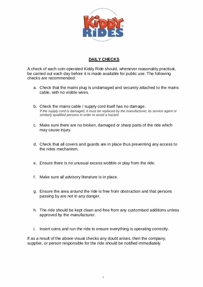
DAILY CHECKS A check of each coin-operated Kiddy Ride should, whenever reasonably practical, be carried out each day before it is made available for public use. The following checks are recommended:
a. Check that the mains plug is undamaged and securely attached to the mains cable, with no visible wires.
b. Check the mains cable / supply cord itself has no damage.
c. Make sure there are no broken, damaged or sharp parts of the ride which may cause injury.
d. Check that all covers and guards are in place thus preventing any access to the rides mechanism.
e. Ensure there is no unusual excess wobble or play from the ride.
f. Make sure all advisory literature is in place.
g. Ensure the area around the ride is free from obstruction and that persons passing by are not in any danger.
h. The ride should be kept clean and free from any customised additions unless approved by the manufacturer.
i. Insert coins and run the ride to ensure everything is operating correctly. If as a result of the above visual checks any doubt arises, then the company, supplier, or person responsible for the ride should be notified immediately.
5
If the supply cord is damaged, it must be replaced by the manufacturer, its service agent or similarly qualified persons in order to avoid a hazard.
6
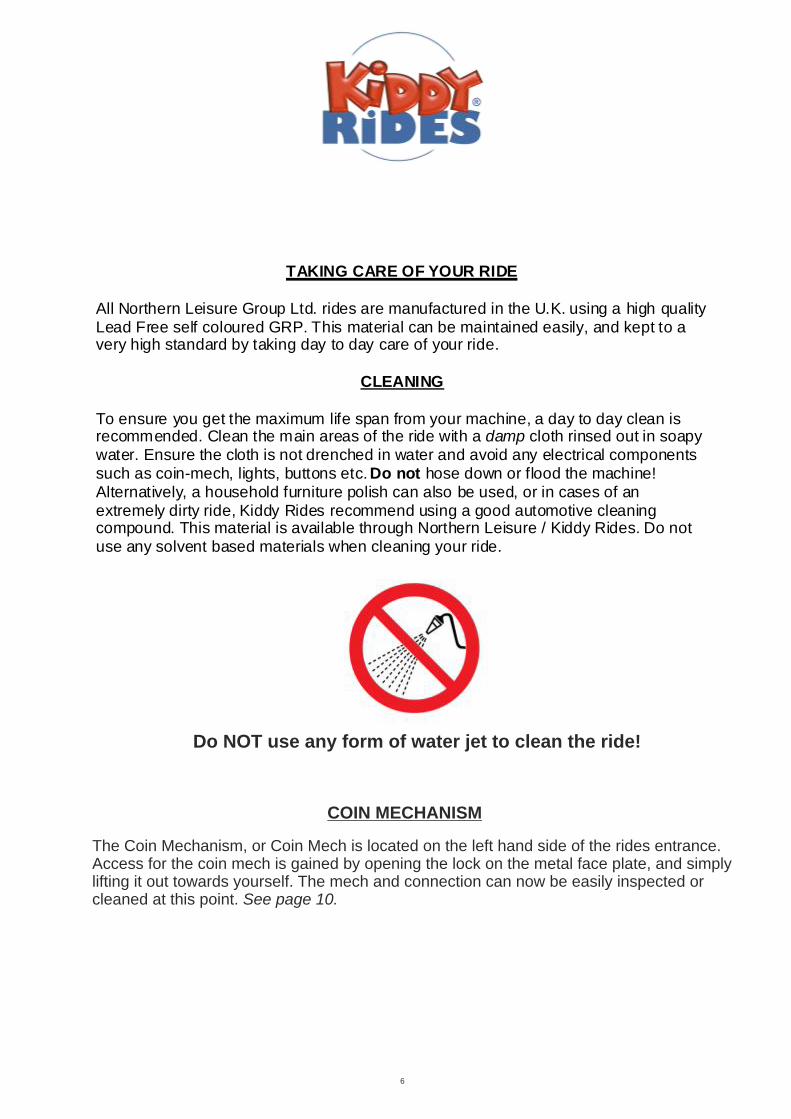
TAKING CARE OF YOUR RIDE All Northern Leisure Group Ltd. rides are manufactured in the U.K. using a high quality Lead Free self coloured GRP. This material can be maintained easily, and kept to a very high standard by taking day to day care of your ride.
CLEANING To ensure you get the maximum life span from your machine, a day to day clean is recommended. Clean the main areas of the ride with a damp cloth rinsed out in soapy water. Ensure the cloth is not drenched in water and avoid any electrical components such as coin-mech, lights, buttons etc. Do not hose down or flood the machine! Alternatively, a household furniture polish can also be used, or in cases of an extremely dirty ride, Kiddy Rides recommend using a good automotive cleaning compound. This material is available through Northern Leisure / Kiddy Rides. Do not use any solvent based materials when cleaning your ride.
The Coin Mechanism, or Coin Mech is located on the left hand side of the rides entrance.Access for the coin mech is gained by opening the lock on the metal face plate, and simplylifting it out towards yourself. The mech and connection can now be easily inspected orcleaned at this point. See page 10.
COIN MECHANISM
Do NOT use any form of water jet to clean the ride!

Standard Operation And Adjustments
Control Box / Timer - The control system in this ride is a ‘Kermit Navigator’ box.This is located behind the rear door on the ride, in this case the door is themed as the Campers Boot/Trunk. It is accessed by removing the 2 bolts using a 4mm hex/allen key.
Once the door is removed, it leaves the Kermit Box, and its connections easily accessible. If required, the box can be removed from the ride by removing the two small allen bolts which hold the mounting tags using a 2.5mm hex key. Once the bolts are removed, simply pull the box upwards disengaging the lower mounting tag. *Ensure all connections to the Kermit Box are disconnected before removal.
Ride Time - The length of time that each ride lasts is pre-programmed, and can not be changed. The standard length for each ride is approximately 90 seconds.
Volume Settings - (The power must remain on, and the ride should be running to adjust the volume settings on this control system.).The volume level of the theme tune can be adjust using the silver toggle switch located on the lefthand side of the Kermit control box (Fig.1). Toggle the switch away from yourself to decrease the volume, and towards yourself to increase the volume. Each movement or toggle adjusts the volume by one level. Toggle the switch multiple times to adjust the level further, do not hold in position.
The pushbutton sound effect volume control buttons are located on the right hand side of the control box as indicated by the diagram on the box lid (Fig.2). There are 2 small buttons (Fig.1), the top one increases the volume (+), and the one beneath it decreases the volume (-).To adjust the level of these, the volume buttons must be pressed when a pushbutton has been activated and the sound effect can be heard.. Please note: The pushbutton must be pressed and the sound effect must be playing in order to adjust the volume.
Fig 1.
7
Fig 2.
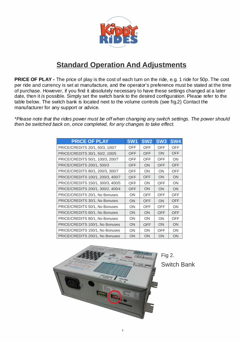
PRICE OF PLAY - The price of play is the cost of each turn on the ride, e.g. 1 ride for 50p. The cost per ride and currency is set at manufacture, and the operator’s preference must be stated at the time of purchase. However, if you find it absolutely necessary to have these settings changed at a later date, then it is possible. Simply set the switch bank to the desired configuration. Please refer to the table below. The switch bank is located next to the volume controls (see fig.2) Contact the manufacturer for any support or advice. *Please note that the rides power must be off when changing any switch settings. The power should then be switched back on, once completed, for any changes to take effect.
Standard Operation And Adjustments
Switch Bank
Fig 2.
8
PRICE OF PLAY SW1 SW2 SW3 SW4PRICE/CREDITS 20/1, 50/3, 100/7
PRICE/CREDITS 30/1, 50/2, 100/5
PRICE/CREDITS 50/1, 100/3, 200/7
PRICE/CREDITS 200/1, 500/3
PRICE/CREDITS 80/1, 200/3, 300/7
PRICE/CREDITS 100/1, 200/3, 400/7
PRICE/CREDITS 150/1, 300/3, 400/5
PRICE/CREDITS 200/1, 300/2, 400/4
PRICE/CREDITS 20/1, No Bonuses
PRICE/CREDITS 30/1, No Bonuses
PRICE/CREDITS 50/1, No Bonuses
PRICE/CREDITS 60/1, No Bonuses
PRICE/CREDITS 80/1, No Bonuses
PRICE/CREDITS 100/1, No Bonuses
PRICE/CREDITS 150/1, No Bonuses
PRICE/CREDITS 200/1, No Bonuses
OFF OFF OFF OFF
OFF OFF OFFON
OFF OFF OFF ON
OFF OFF OFFON
OFF OFFON ON
OFF OFF ON ON
OFF OFFON ON
OFF ON ON ON
ON OFF OFF OFF
ON ONOFF OFF
ON ONOFF OFF
ON ON OFF OFF
ON ON ON OFF
ON ON ONOFF
ON ON ONOFF
ON ON ON ON

Inspection of Features & Components
Front Headlamps - Continuously flash when power is on. Remove 2screws (+) to change LEDbulbs.
9
Rear Hatch - Remove to gain access.
Rear Lamps - Continuously flash whenpower is on.
ENTRANCEFRONT WINDSCREEN
Internal Dashboard Hatch
Rear Hatch - Kermit Control System & Connections, Rear Body/Base Fixings, Speakers, Rear Light Connections, Rear Buttons & Connections.
Internal Dashboard Hatch - Remove the two M6 Hex/Allen bolts using a 4mm Hex/Allen Key to gain access to:Spare Wheel Fixings. Headlamp Connections. Buttons, Bulbs & Switches. Steering Wheel Mountings. Monitor Screen & Connections.
Coin Mech Face Plate - Remove by unlocking with the key supplied and carefully lift up and out towards yourself. This gives access to:Coin Mechanism, Ribbon Cable, Start Button, Start Bulb, Connections, Coin Chute.
Metal Inspection Door - Open door by unlocking with key supplied. Door hinges to the right. This gives access to:Coin Chute, Coin Meter/Counter.
Front Headlamps & Rear Lamps - Remove the two screws (+) to gain access to the LED bulb.
Remove the two M6 Hex/Allen bolts using a 4mm Hex/Allen Key to gain access to:
Metal Inspection Door
Coin Mech Face Plate
Start Button
Steering Wheel
Video Screen
Pushbuttons
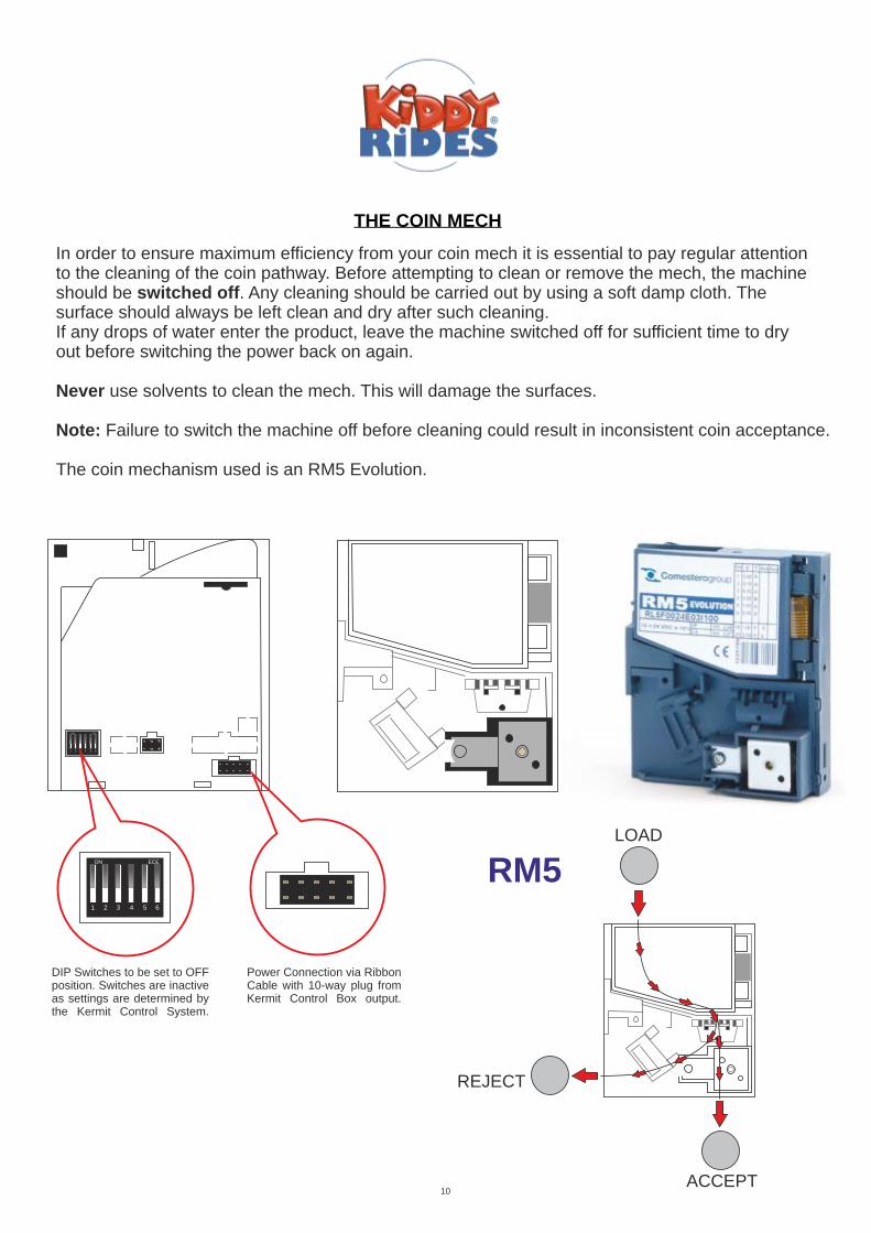
THE COIN MECH
In order to ensure maximum efficiency from your coin mech it is essential to pay regular attentionto the cleaning of the coin pathway. Before attempting to clean or remove the mech, the machineshould be switched off. Any cleaning should be carried out by using a soft damp cloth. The surface should always be left clean and dry after such cleaning.If any drops of water enter the product, leave the machine switched off for sufficient time to dryout before switching the power back on again.
Never use solvents to clean the mech. This will damage the surfaces.
Note: Failure to switch the machine off before cleaning could result in inconsistent coin acceptance.
The coin mechanism used is an RM5 Evolution.
10
ON ECE
1 2 3 4 5 6
ON ECE
1 2 3 4 5 6
DIP Switches to be set to OFFposition. Switches are inactiveas settings are determined bythe Kermit Control System.
Power Connection via RibbonCable with 10-way plug fromKermit Control Box output.
LOAD
REJECT
ACCEPT
RM5
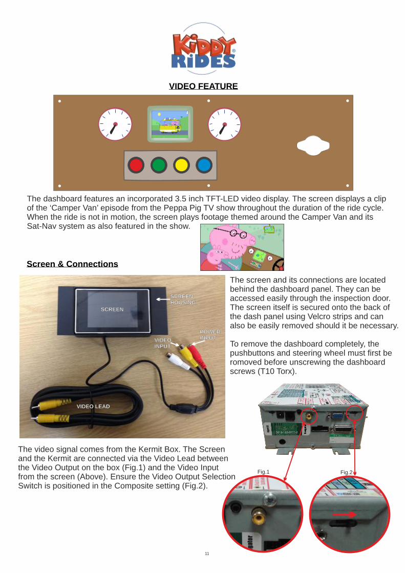
VIDEO FEATURE
The dashboard features an incorporated 3.5 inch TFT-LED video display. The screen displays a clipof the ‘Camper Van’ episode from the Peppa Pig TV show throughout the duration of the ride cycle.When the ride is not in motion, the screen plays footage themed around the Camper Van and itsSat-Nav system as also featured in the show.
SCREEN
SCREENHOUSING
VIDEO LEAD
POWERINPUTVIDEO
INPUT
The screen and its connections are locatedbehind the dashboard panel. They can be accessed easily through the inspection door.The screen itself is secured onto the back of the dash panel using Velcro strips and can also be easily removed should it be necessary.
To remove the dashboard completely, thepushbuttons and steering wheel must first beromoved before unscrewing the dashboard screws (T10 Torx).
The video signal comes from the Kermit Box. The Screenand the Kermit are connected via the Video Lead betweenthe Video Output on the box (Fig.1) and the Video Input from the screen (Above). Ensure the Video Output Selection Switch is positioned in the Composite setting (Fig.2).
Fig.1 Fig.2
11
Screen & Connections

WIRING SCHEMATICS
MotorM
Filter
. . . . . . . . . . . . .. . . . . . . . . . . .
13
12
34
56
78
91
01
11
2
25
14
15
16
17
18
19
20
21
22
23
24
Pushbutton 2
Pushbutton 1
StartButton
4
3
2
1
4
3
2
1
Lamps/Flasher (All buttons, headlamps & tail lights)
Video
Co
mp
osite
Vid
eo
(Ph
on
o L
ea
d)
Composite Video (Phono Lead)
VideoDisplayScreen
(2.1mm D.C. Plug)
2.1mm Power Plug has +12V to Inner Connection
Mains Supply240VAC
Kermit NavigatorWith Video
IEC CE22 Mains Inlet
Video OutP5
P6
P2
P4
P4
P10
P3P9
GND
RX
TX
+12V
Speaker 1
Speaker 2
Vid
eo
Au
dio
Ou
t (3.5
mm
Jack P
lug
)
Audio Out 0 0 0 0 1 5
Meter
Power
StartLamp
. . . . . . . .. . . . . . .
12345678
10 91112131415
Pushbutton 3
P6Coin Mech
Pushbutton 4 Pushbutton 5 Pushbutton 6
To CashlessPayment System(if fitted)
12

Colour Ref.: Function / Destination: Plug / Pin No:
P6 / 2White / Red
P6 / 5Purple
Red Start Lamp + P4 / 18
Yellow Lamps - Buttons, Headlights, Tail Lamps
Lamps - Buttons, Headlamps, Tail LightsYellow / Black
P10 / 3
P10 / 4
Top Loom Reference - refer to diagram.
13
Pushbuttons 4 & 6 (common for 6)
Pushbuttons 3, 4 & 5 (common)
Black/White (2-core)
Black (2-core)
Speaker 2
Speaker 2
Kermit Audio Out / Jack Plug
Kermit Audio Out / Jack Plug
Orange Pushbutton 3 P6 / 6
Green / Blue Cashless Payment System (when fitted) P6 / 7
Red / Blue Pushbutton 6 P6 / 9
Black Cashless Payment System (when fitted) P6 / 11
Black / White Pushbutton 5 P6 / 12
Grey / Black Video Screen (-12V) P4 / 3
Blue Meter/Counter (-12V) P4 / 4
Brown Start Lamp P4 / 5
Black Pushbuttons 1, 2 & Start (common)
Black/White (2-core)
Black (2-core)
Speaker 1
Speaker 1
P4 / 6
P4 / 12
P4 / 13
Red / Green Video Screen (+12V) P4 / 15
Red / Black Meter/Counter (+12V) P4 / 17
Pink Start Button P4 / 19
Green Pushbutton 1 P4 / 20
White Pushbutton 2 P4 / 21
AV Lead Screen Video Input Kermit Video Out / Screen
. . . . . . . . . . . . . . .
12345678
9101112131415
PIN No WIRE COLOURS USE
1
2
3
4
5
6
7
8
White & Red
Purple
Pushbutton 3,4,5 (Com)
. . . . . . . . . . . . .. . . . . . . . . . . .
13 123456789101112
25 1415161718192021222324
PIN No WIRE COLOURS USE
1
2
3
4
5
6
7
8
9
10
11
12
13
15
Brown
Black & White
14
16
17
18
19
20
21
22
23
24
25
PIN No WIRE COLOURS USE
Blue
Black
Meter
Start Lamp -
Start Switch
Speaker
Speaker
Red & Blue
Red
Pink
Green
White
Meter (+12V)
Start Lamp + (+12V)
Start Button
Pushbutton 1
Pushbutton 2
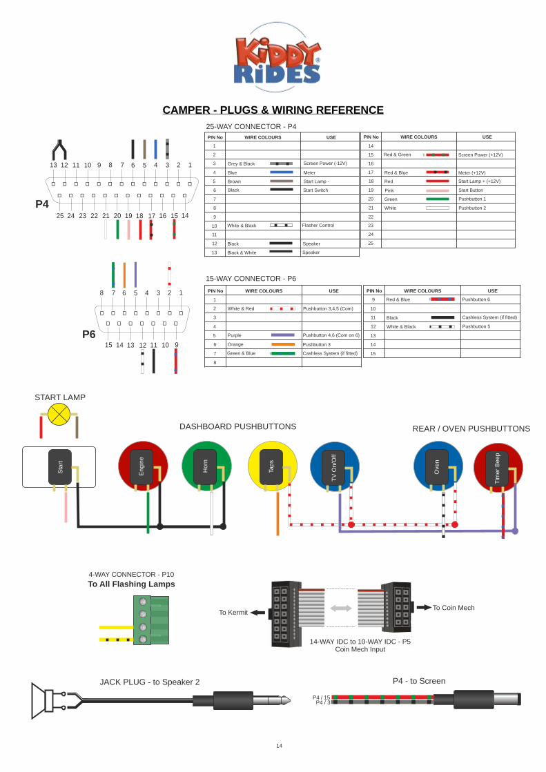
15-WAY CONNECTOR - P6
25-WAY CONNECTOR - P4
Pushbutton 4,6 (Com on 6)
CAMPER - PLUGS & WIRING REFERENCE
DASHBOARD PUSHBUTTONS
Black
White & Black Flasher Control
Grey & Black
Red & Green
Screen Power (-12V)
Screen Power (+12V)
Orange Pushbutton 3
Green & Blue Cashless System (if fitted)
TV
On
/Off
Tap
s
Sta
rt
Ove
n
Tim
er
Be
ep
Ho
rn
En
gin
e
REAR / OVEN PUSHBUTTONS
4-WAY CONNECTOR - P10
To All Flashing Lamps
To Coin MechTo Kermit
14-WAY IDC to 10-WAY IDC - P5 Coin Mech Input
JACK PLUG - to Speaker 2 P4 - to Screen
P4 / 3P4 / 15
PIN No WIRE COLOURS USE
9
10
11
12
13
14
15
Red & Blue
Black Cashless System (if fitted)
White & Black Pushbutton 5
Pushbutton 6
P6
P4
START LAMP
14
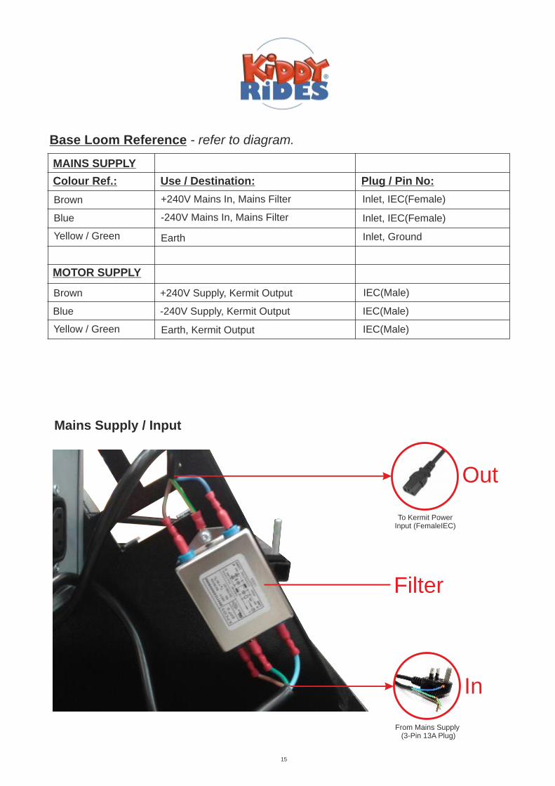
Colour Ref.: Use / Destination: Plug / Pin No:
Brown +240V Mains In, Mains Filter Inlet, IEC(Female)
Base Loom Reference - refer to diagram.
Blue -240V Mains In, Mains Filter Inlet, IEC(Female)
Yellow / Green Earth Inlet, Ground
MAINS SUPPLY
MOTOR SUPPLY
Brown
Blue
Yellow / Green
IEC(Male)
IEC(Male)
IEC(Male)
15
+240V Supply, Kermit Output
-240V Supply, Kermit Output
Earth, Kermit Output
In
Filter
Mains Supply / Input
Out
To Kermit PowerInput (FemaleIEC)
From Mains Supply (3-Pin 13A Plug)

Ref. Description123456789
1011121314151617181920212223242526
Motor
Gearbox
Crank Bearing
Alloy Crank Block
Crank Spacer
Earth Points
Gearbox Pulley
Motor Pulley
Drive Belt
Motor Cable
Base Components
24
8,14
16
15
17
19
20
21
22
Mains Filter
Mains Lead
Kermit / Control Box
Kermit / Control Box Mounting Bolts
Kermit / Control Box Mains In (Male IEC)
Motor Supply Inlet
Base Castors
Rocker Cradle
Rear Body Mounting Bolts
Front Body Mounting Bolts
16
21
1
11
23
Motor Inspection Cover
13
Motor Output (Female IEC)
6
14
Mains Inlet Clamp
Mains Lead Protector
7
2
9
3
Motor Capacitor
25
1810
6
26
Motor Mounting Bobbins
13
5
4
6
25

Parts List - Upper Body
DESCRIPTION OF PARTS QUANTITY ITEM REF.
Coin Mech 1 RM5-V00
Coin Mech Mini Face Plate 1 RM5 Mini Face Plate
Coin Mech Metal Surround 1 Security Mech Surround
Coin Chute 1 Camper Coin Chute
Lock 2 Sale Lock
Meter / Counter 1 Base Meter
Speaker 2 Speaker
Speaker Cover 2 KR Speaker Cover
Body/Base Bolt Access Cover 1 KR Speaker Cover
Button Round 6 Small Round Button
Button Rectangle 1 Rectangle Button
Button Bulb 7 LED Wedge Bulb
Headlamp / Tail Light Bulb 4 G4 LED
Headlight Lens 2 Opal Acrylic Disc 98mm
Tail Light Lens 2 Red Acrylic Disc 64mm
Steering Wheel 1 Peppa Steering Wheel
Steering Wheel Bearing 2 UFL00 Bearing
Steering Wheel Spacer 1 20mm Oilite Bush
Steering Wheel Fixing 1 M10 Button Head Bolt & NylocK
Floor Tape 1 Camper Floor Tape
Aluminium Edging/Step Plate 1 Camper Edging Plate
Wiring Loom/Main Loom 1 Camper Main Loom KR-008
Character Peppa 1 Peppa Character
Character George 1 George Character
Seat Belt 2 Peppa Seat Belt
17
Continued overleaf...

Parts List - Upper Body Continued
DESCRIPTION OF PARTS QUANTITY ITEM REF.
Monitor Screen 1 3.5" Screen
Screen Housing 1 3.5" Screen Housing
Dashboard Panel 1 Camper Dash Panel
Mummy Pig Window Graphic 1 Mummy Pig Camper Panel
Daddy Pig Window Graphic 1 Daddy Pig Camper Panel
Peppa & George N/S/R 1 Near Side Rear Camper Window Panel
Peppa & George O?S/R 1 Off Side Rear Camper Window Panel
Rear Window Graphic 1 Camper Rear Window
18
Mummy Pig Window Graphic Daddy Pig Window Graphic
Peppa & George N/S/RPeppa & George O/S/R
Rear Window Graphic
Dashboard Panel
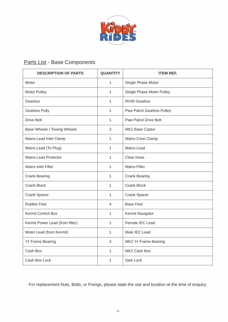
Parts List - Base Components
DESCRIPTION OF PARTS QUANTITY ITEM REF.
Motor 1 Single Phase Motor
Motor Pulley 1 Single Phase Motor Pulley
Gearbox 1 RV40 Gearbox
Gearbox Pully 1 Paw Patrol Gearbox Pulley
Drive Belt 1 Paw Patrol Drive Belt
Base Wheels / Towing Wheels 2 MK2 Base Castor
Mains Lead Inlet Clamp 1 Mains Conn Clamp
Mains Lead (To Plug) 1 Mains Lead
Mains Lead Protector 1 Clear Hose
Mains Inlet Filter 1 Mains Filter
Crank Bearing 1 Crank Bearing
Crank Block 1 Crank Block
Crank Spacer 1 Crank Spacer
Rubber Feet 4 Base Feet
Kermit Control Box 1 Kermit Navigator
Kermit Power Lead (from filter) 1 Female IEC Lead
Motor Lead (from Kermit) 1 Male IEC Lead
‘H’ Frame Bearing 4 MK2 ‘H’ Frame Bearing
Cash Box 1 MK2 Cash Box
Cash Box Lock 1 Sale Lock
19
For replacement Nuts, Bolts, or Fixings, please state the use and location at the time of enquiry.

Removal Of Body Shell (2 persons required)
To remove the Body Shell from its base you must gain access to the four Body Mounting Bolts.
The first is located just inside of the entrance floor, infront of the metal inspection door. Remove this dome headed Allen bolt using a 5mm Hex/Allen Key.
The second front fastening is located inside of the front driver seat. To access this, remove the grill on the side of the seat . Once removed, this reveals an opening and the body/base mounting can be reached through this. Once located remove the bolt and washers using a 13mm socket wrench or spanner.
The back mounting bolts are accessed through the rear door on the ride. Remove the two AllenBolts from the hatch using a 4mm hex key and lift the door towards yourself. Directly in front of you through the opening is the Kermit Control Box and all it’s connections. Behind this is the wooden floor of the ride where you will find the two rear bolts. Remove the nuts using a 13mm socket orspanner.
Once all four mountings are removed ensure you disconnect all connections to the Kermit Box. Making sure that all wires & connections are unplugged and free from snagging, the body shell can now be removed from the base mechanism by lifting the body upwards.
*Please note that it is recommended that two or more people should be used to lift off theshell. The shell needs to be lifted until the base of the shell is clear of all base components.manual handling and lifting guidelines should be followed, as set out by the HSE. This canbe found by visiting
Once the ride is separated, a full inspection of the Base Mechanism can be carried out.This level of maintenance should only be carried out by a competent person. If care is nottaken when inspecting or servicing the ride, there may be risk of damaging componentsor personal injury.
www.hse.gov.uk
Ensure the power is turned off before carrying out any of the following procedures!
20
VO
ID S
PA
CE
FO
R A
CC
ES
S
FR
ON
T
ENTRANCE
2
1
2
1
3
3

For advice and support on any problem, please call our Technical Dpt. on +44 (0)113 239 38 03 or email [email protected]
SYMPTOM CHECK
No lights / self test message
Mains voltage supply.Mains supply to control box.Green 4-way plug on control box.2x yellow wires into 4-way plug.Break in connection to yellow wires to lamps.
Coins do not accept
Check mains power is on.Voltage to coin mech.Ribbon Cable disconnected / broken.Faulty mech.
Coins accept but meter / counter does not turnCheck connections to meter / counter.Check wires on ‘D’ plug to control box.Faulty meter
Ride will not start.Meter turns when coins are inserted but will notoperate the start button prompt when the creditis reached.
Start Button ConnectionFaulty Start Switch..Control box / ‘D’ plug.Faulty Control Box.
When start button is pressed, sound operates butno movement occurs.
Motor connection to Kermit Box.Broken Drive Belt.Loose motor pulley.Faulty Motor or Start Capacitor.Faulty Kermit.
The ride is working but the Monitor screen does not display.
Check power lead is connected to screen.Check AV lead is plugged in to Kermit and screen.Check screen power wires in 25-Way D-Plug (referto pages 12,13 & 14).
No sound.
Check speaker connections.Check volume settings.D-Plug connections.Faulty Speaker.
FAULT FINDING
To be carried out by a competent person.
21

Orders, Spares, and Repairs
TELEPHONE Call us on +44 (0) 113 2393803 Confirm your order by 2.00pm and we will ship the same day. If goods aren’t in stock, you will be given an expected shipping date before confirming your order.
FAX Fax us on +44 (0) 113 2363194 Confirm your order by 2.00pm, and we will ship stock items the same day. POST- Send us an order by post. If you don’t have an account with us, please include payment for the full amount including delivery and VAT. E-MAIL E-mail your order directly to [email protected] or browse our web pages at www.kiddyrides.co.uk and e-mail us directly from there. METHODS OF PAYMENT Subject to approval, we offer thirty day Credit Accounts. Please call for more information. If you are not an account holder, you can post a cheque along with your order. We would also welcome receiving your payment by BACS direct credit. Please contact us for more details. Northern Leisure Group also accept payment from all major debit and credit cards. Please note that a fee of 3% will be added for credit card payments only. If you have any queries regarding an account, then please contact us. You can also get information by e-mailing our accounts dept. at [email protected]
NO MINIMUM ORDER VALUE We want you to order what you want, when you want it. So you can order whatever quantities you like from Kiddy Rides, and you won’t be penalized with a minimum order value.
ON-SITE REPAIRS If you are unable to return parts for repair, or fit spares yourself, we can arrange for one of our regional engineers to make a site visit. Just call for details.
HOURS OF BUSINESS Our office and sales lines are open Mon – Fri: 9.00am to 5.30pm. You can still call our number ( +44 (0) 113 239 38 03 ) outside these hours, and leave a message with our pager service. Alternatively, you can contact us by fax or e-mail.
All goods are supplied on the conditions that Northern Leisure shall not be liable for any direct or consequential damage arising from delay in delivery or from defective material, other than is covered by our usual form of guarantee. Whilst every effort is made to ensure the accuracy of the particulars contained in this book, modifications and specification changes to kiddie rides are on going. These may affect the information specified.
22
Northern Leisure Group Ltd. Unit 4 Kingsmark Court, Intercity Way, Leeds LS13 4PN, West Yorkshire, United Kingdom

DATE PROCEDUREService / H&S / Repair
ENGINEER COMPANY COMMENTS
REPAIR, SERVICE, AND HEALTH & SAFETY RECORD
To be filled in by Engineer at time of work being carried out
23
DATE PROCEDUREService / H&S / Repair
ENGINEER COMPANY COMMENTS
REPAIR, SERVICE, AND HEALTH & SAFETY RECORD
To be filled in by Engineer at time of work being carried out
24

YOUR NOTES
25

YOUR NOTES
26

CE DECLARATION OF CONFORMITY
Manufacturer: Northern Leisure Group Ltd., Unit 4 Kingsmark Court, Intercity Way, Leeds, LS13 4PN, U.K.
Details Of Electrical Equipment
Type No:
Description:
Directives This EquipmentComplies With:
Harmonised standards appliedin order to verify compliancewith Directives:
Authorised Signatory:
Name: Date Of Issue:
Position: Place Of Issue:
2
Coin Operated Childrens Ride
Electrical Equipment (Safety) Regulations 1994, SINo3260 (Regulation 5. (1)).Electromagnetic Compatability Directive 89/336/EECLow Voltage Directive 72/23/EEC (article 2) asamended by 93/68/EEC
EN 50081-1:1992EN 50082-1:1992EN 60335-1:1994 inc. AMDS A11, A1, A12, A13,A14, A2, A15 and A16 - Safety Of Household andSimilar Electrical Appliance. EN 55014-1: 1993EN 61000-3-2:1995 + A1: 1998 + A2: 1998EN 61000-3-3: 1995 EN 55014-2: 1997 Category 2 EN 60335-2-82: 2000 - Particular Requirements for Service Machinesand Amusement Machines
RoHS SUPPLIER DECLARATION
As of July 1st 2006 unless otherwise stated on order confirmations, all products manufactured byNorthern Leisure Group Ltd. are manufactured in accordance with RoHS directive 2002/95/EC
Manufacturer
Richard Pike
Technical Manager
June 2016
Leeds, England

Test Certificate
Eurofins York
Unit 5, Speedwell Road
Castleford, West Yorkshire
WF10 5PY
Tel: 01977 731173
LVDFORM 414 Issue 5
Issued to: -
Northern Leisure Group Ltd
4 Kingsmark Court, Intercity Way, Leeds, LS13 4PN, United Kingdom
Safety Tests were performed on the apparatus as detailed: -
Description Kiddie Ride – Single-phase motor
Type number Single-phase - MK2 Base
Serial Number/s NLG003CH
Date received 20 September 2017 Dates Tested 5 October 2017 to 25 January 2018
Specification/s EN 60335-2-82 Household and similar electrical appliances – Safety – Part 2-82: Particular requirements for amusement machines and personal service machines
The apparatus to which this certificate relates was tested against the above specifications. Full results are contained in Eurofins York safety test report C12579TR1. The apparatus was found to be compliant to the above specifications with the exception of the following clauses which are outside the laboratories testing capabilities: Clause 19.9: Running overload test
Clause 19.11.4.7: Mains signal tests of IEC 61000-4-13
Opinions and interpretations expressed herein are outside the scope of UKAS Accreditation.
These results apply only to the particular EUT submitted, in the configuration used and in the mode of operation tested.
Abnormalities/Departures from Standard Conditions
None
Opinions/Interpretations/Additional information
None
Certificate No: -
C12706TC1
Project No: -
C3564
Date: -
9 February 2018
Page 1
of 1
Tested by: -
P Hesp: Senior Test Engineer
Approved signatory: -
E Warren: Principal Engineer
The Copyright in this certificate is vested in Eurofins York. The Certificate may be reproduced in its entirety but reproduction of any extract is expressly forbidden.

NORD COMPOSITES
TECHNICAL DATA SHEET
NORESTER® 976 Fire retardant resin
NTR 252 A - 12/11/12 Page : 1/2
IMPORTANT All of the results obtained according to trials in our laboratory. However, we don’t be responsible of manufactured parts with the
resin NORESTER®
976, if the application conditions specified are not respected. The user must also ensure that his application is appropriate for this product to be used. We hereby the conformity of our products with the above specifiations. We cannot be responsible for any damage caused by misuse of this product.
ZA – route d’Amiens – 80890 Condé-Folie – FRANCE – Tél : 03.22.31.57.57 – Fax : 03.22.31.86.97
1 CHARACTERISTICS
The resin Norester® 976 is a fire retardant resin fomulated from polyester orthophtalic resin. It is thixotropic, filled, halogen free and antimony oxide free.
Application hand lay-up and spray-up Polymerise at room temperature with addtion of MEKP. Good wetting out of reinforcements. Low styrene emission in application.
Norester® 976 is an opaque resin and gives laminates, which answer to this following classification: Class 2 according to the norm BS476 part 7 (Certificate N°280792 dated on 02/10/12).
2 PROPERTIES OF THE LIQUID RESIN
Aspect White liquid
Brookfield viscosity (ISO 2555 - 20°C – sp3)
50 rpm : 1000 - 1200 cPs
Specific gravity (ICON 012)
1.33 - 1.37 g/cm3
Gel time Not pre-accelerated version (NPA) (ICON 002) (20°C - 0.1% CO6%, 2% MEKP on 100 g)
18 - 22 minutes
Gel time Pre-accelerated version (PA) (ICON 002) (20°C - 2% MEKP on 100 g)
11 - 15 minutes
Non volatile content (ICON 003)
65 - 69%
3 MECHANICAL PROPERTIES OF THE CURED RESIN ON LAMINATE
Flexural strength * (ISO 178)
187.2 MPa
Flexural modulus * (ISO 178)
8.025 GPa
Tensile strength * (ISO 527)
113.7 MPa
Module de traction * (ISO 527)
2.127 GPa
Glass content 33.88%
Barcol hardness * (ASTM 2583)
50
* Mechanical tests realised on a laminate made with 4 layers 450 g/m², pre accelerated resin with 0.1% Co6% and catalyzed at 2% of MEKP. Post cure: >24h at room temperature and 3 hours at 80°C.
4 MECHANICALS PROPERTIES OF CURED CAST RESIN
Flexural strength * (ISO 178)
49.54 MPa
Flexural modulus * (ISO 178)
4.835 Gpa
GRP
NORD COMPOSITES
TECHNICAL DATA SHEET
NORESTER® 976 Fire retardant resin
NTR 252 A - 12/11/12 Page : 2/2
IMPORTANT All of the results obtained according to trials in our laboratory. However, we don’t be responsible of manufactured parts with the
resin NORESTER®
976, if the application conditions specified are not respected. The user must also ensure that his application is appropriate for this product to be used. We hereby the conformity of our products with the above specifiations. We cannot be responsible for any damage caused by misuse of this product.
ZA – route d’Amiens – 80890 Condé-Folie – FRANCE – Tél : 03.22.31.57.57 – Fax : 03.22.31.86.97
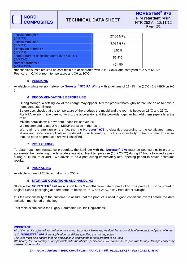
Tensile strength * (ISO 527)
27.06 MPa
Tensile Modulus* (ISO 527)
3.024 GPa
Elongation at break * (ISO 527)
1.50%
Temperature of deflection under load * (HDT) (ISO 75-3)
57.4°C
Barcol hardness * (ASTM 2583)
45 - 50
*mechanicals tests realized on cast resin pre accelerated with 0.1% Co6% and catalyzed at 2% of MEKP Post-cure : >24H at room temperature and 3H at 80°C
5 VERSIONS
Available in white version reference Norester® 976 PA White with a gel time of 11 -15 min (20°C - 2% MEKP on 100
g).
6 RECOMMENDATIONS BEFORE USE
During storage, a settling low of the charge may appear. Mix the product thoroughly before use so as to have a homogeneous mixture.
Before use, check that the temperature of the product, the mould and the room is between 18°C and 25°C. For NPA version, t ake care not to mix the accelerator and the peroxide together but add them seperatly in the
resin. Mix the peroxide well, never put under 1% or over 2% We recommend to add 2% of MEKP peroxide in the resin. We retain the attention on the fact that the Norester® 976 is classified according to the certificates named
above and tested on applications produced in our laboratory. It is the responsibility of the customer to assure that the parts he produces are well classified.
7 POST CURING
To obtain optimum resistance properties, the laminate with the Norester® 976 must be post-curing. In order to accelerate the hardening, the laminate stays at ambient temperature (16 à 20 °C) during 24 hours followed a post-curing of 16 hours at 40°C. We advise to do a post-curing immediately after ripening period to obtain optimums results.
8 PACKAGING
Available in cans of 25 Kg and drums of 250 Kg.
9 STORAGE CONDITIONS AND HANDLING
Storage life: NORESTER® 976 resin is stable for 3 months from date of production. The product must be stored in original closed packaging at a temperature between 15°C and 25°C, away from direct sunlight. It is the responsibility of the customer to assure that the product is used in good conditions overall before the date limitation mentioned on the keg. This resin is subject to the Highly Flammable Liquids Regulations.


