
INSTRUCTION MANUAL
PCM-875PLASMA ARC CUTTING PACKAGE
F15-335-E July, 2007
These INSTRUCTIONS are for experienced operators. If you are not fully familiar with the principles of operation andsafe practices for arc welding and cutting equipment, we urge you to read our booklet, "Precautions and SafePractices for Arc Welding, Cutting, and Gouging," Form 52-529. Do NOT permit untrained persons to install, operate,or maintain this equipment. Do NOT attempt to install or operate this equipment until you have read and fullyunderstand these instructions. If you do not fully understand these instructions, contact your supplier for furtherinformation. Be sure to read the Safety Precautions before installing or operating this equipment.
Be sure this information reaches the operator.You can get extra copies through your supplier.
This manual provides installation and operation instructions for the following PCM-875 cutting packages starting with Serial No.PHJ205001:
P/N 36590 - 208/230 V, 1 & 3-Phase, 50/60 HzP/N 36592 - 460 V, 3-Phase, 50/60 HzP/N 36714 - 575 V, 3-Phase, 60 HzP/N 36725 - 400 V, 3-Phase, 50/60 Hz

This equipment will perform in conformity with the description thereof contained in this manual and accompanying labels and/or inserts when installed, operated, maintained and repaired in accordance with the instructions provided. This equipment must be checked periodically. Malfunctioning or poorly maintained equipment should not be used. Parts that are broken, missing, worn, distorted or contaminated should be replaced immediately. Should such repair or replacement become necessary, the manufacturer recommends that a telephone or written request for service advice be made to the Authorized Distributor from whom it was purchased.
This equipment or any of its parts should not be altered without the prior written approval of the manufacturer. The user of this equipment shall have the sole responsibility for any malfunction which results from improper use, faulty maintenance, damage, improper repair or alteration by anyone other than the manufacturer or a service facility designated by the manufacturer.
BE SURE THIS INFORMATION REACHES THE OPERATOR.YOU CAN GET EXTRA COPIES THROUGH YOUR SUPPLIER.
These INSTRUCTIONS are for experienced operators. If you are not fully familiar with the principles of operation and safe practices for arc welding and cutting equipment, we urge you to read our booklet, “Precautions and Safe Practices for Arc Welding, Cutting, and Gouging,” Form 52529. Do NOT permit untrained persons to install, operate, or maintain this equipment. Do NOT attempt to install or operate this equipment until you have read and fully understand these instructions. If you do not fully understand these instructions, contact your supplier for further information. Be sure to read the Safety Precautions before installing or operating this equipment.
CAUTION
USER RESPONSIBILITY
READ AND UNDERSTAND THE INSTRUCTION MANUAL BEFORE INSTALLING OR OPERATING.
PROTECT YOURSELF AND OTHERS!

!"#
!"#$%& #$#'! ()*!()+)*+)(,
!"#$%& -!"+$(#$%& $%% & $%' $%( ! $%) *
!"#$%&. $&#)'')#$%& %+'% & %+'' ,- %+'( . %+') / %+'0 ,/1 %+'2 31 %%'$ 11*$0'++4'+*56/ %('* "1/ '+! %)
!"#$%& %(!+)#$%& %2(% 3 %2(' 1*$01 %2(( 1 '$ %2() 11 %*
!"#$%&/ 0)$&#!&)&"! %7)% & %7)' /1 %7)( '$1 %7)) 8 '+)0 /&9:- '+
!"#$%& #+%1'!,%%#$&* '%0% '%0' & '%0( -61 '00) 3 '2
!"#$%&2 +!(')"!0!&#()+# ($2% & ($2' 3 ($

! !! " # $
++ !! " #$%%% "$ %& " $' $ "$#$!!( ) "$ * !) % !% !$"+! ,-. " !)$ $""! "
" / $ %* " &%( ! !" " " % 0 $%($" !) #$#$ % 1 !) #$%%% " ' #2! % %%!" ! #$+! "!%( )$1$
% !! !! & #! '
(! # & & ! # ) ! *#
) ### ! & &
+ , & # &# & &
- &!
. (# ! / ! #
3 22"! 1$1"% " "$% " %!"$! 1$%( ! %"$ %#"$*% " "% " % 1$% " 42#%%( )$1$
% 0# !! ! & # ! # # / !!'#
, & & # ! !1& &2
3 ! ! & ! & ! &! *# 3! & *
+ ,# *' ! & *
- 3' " *# ! #
. ! & & & ! ( ! !
4 " 5" -%6" # ( / ) 6# 5" &718.9
5 22 !"! !) +!$" #"$!% " $ " " %%+$ / $& $ "!)( % $$! "# "$"% 1 +2! % 1 $ 1 !)$ % "$ 11"(
% ! :; !
/! & / ! & ! &
* &
+ (!'0!
- < # ! & = !
. 1& ! &
4 3 !! &' > !
? # ! 9 ! # #
%8 0 5=/ @+9%:*; 3 &! &
6 76"& 0 "$ %( !$ $$! 12 !)$ ) "& !$ " %% 2"8 !$ " 6"! %,6.( " !! $$! $2"!% 6 "$ "0% " ")%( )$1$
% ) #& !A1" !&
A* A1"# ! &!
) ! * A1"B 0 ! &
!! 5# ! & / 3 ! ! &
0 3 /! & ! &
!A <!! !

+
6 22 % ""%% " " % %1$! $ )"$#"$! "$& 1 %#"%( ! 0$"!) 1 % " "%%( )2 "%% " " % "%#)&4"!()$1$
% ! #'#! & 3! # ## #3
3 ! # *
# ! #'! && ## ! & 3
+ 0 5=/ @+9%: !; #
22 &$% 1%)" " $ #! $ " +!&$"% "%( $ #! $ 1 &2$ +"+ $ $1 + " / $ $*( )$1$
% ( 3 1 "! C
! & ! & 5# ! & * !
) & ## ,### # &#
+ D ! & 5# &
- " /E %6 ,/ E/ 6 ! # / E%-F 3#,! G8
96 6 22 " !& $ 2#$#$& "!" ' #! " " %/ $& $ "!)( )$1$
% ! # ' ! & 3
! & ' ! &
! &! ! !
1 ! ! ! ! & 3 '
+ 3 ' <'! !! # !
- <# #
. ( ' 3
6 22 $$ 1$"! %"1 #$"!% 1$ 2!$ "$ " !! ' #! "%*& $ % ##$ 1$ " #& 1 :$" !% ""1 $"!% 1$ $ !! " : $ ;<2;<=(
! ! # )--85)DF01"D%. B% 5=/@+9%6)/6 )/-% 60
)6 )/- 60
/6+ )/-60 /
E/6- )/--60 E
)2. )/-.60 E1
)624 )6 60 ), &? 5=)"+%60 )
// ,#,, 6
!!!> ? $!> $ %"1!& %++(
! 35EA0 )055E/(H5 B
( !#! $
( ! $
( ! $

-
! " # $ !
% & ! ' &
( $ ! )
* " ) !
+$ , ) & ) )
- ./ %* 0123+*% 4 ) " ) % ) ,
( $ & ) " '$
5 $ ) $
6$ & 7
( $& ( $ & +$ & )
6$) ) ) ) ( ) )
'$ ) $ % $ ) 8
9'*10255*6*(0: & '$ ) 0 ) 8 ; <1/0* 02/( 2(=2'2=+*%%* % >
! ! ) ) 9 :
<$ ) ) ! ! ) ) $ ) $
9'*10255*? ,) ) !
<$ ) ) ! ) , !)
% & ) 9 "
<$ ! ) )
(& ) $ +$ ) > %) "& %
% "@;AA;;BCD)
E<1'*(02/(=*5 2( *(=*5%& ) ) $ 9 :

.
) *"$ " 7 1$
B'*(02%902/(% 7 ) 9 :
9 $ ) ! ) ( $ & $ ! !) "
( $ & ! % ! $ ) $
+! $ ) 9"$ ( $
! % " ! ) 4 ) /(@6D '$ F , (&
% ) 9 ) !
$ ) G ?BH;9I5
J *(01*02*( =* %3+2<*6*(0 + ) , ) ) ) 8
) /$) :
*$ & ) ( $ ) ) ")
( $ & ) ) 7 )
6$ 7 ( $& ) ) )
<$ ) K$ ) $
%$
+$ 7 $
G 2(L/16902/(5 /6<%6*(0921*51*%902'*5M%95 +120
< ) ) $ (NJEJEHO< 5<9I K P *59C ( 9I5!JJA(I%Q 16L%-E;EG:
O5!I P9I5?BH; O15< K59IO9I59G;
O5 < I 0.. P9I59GA
O1 5 < < 9 P9I59G-
O15<<9IP9I5 J;
O1 5 < 9 9K P9I5 J-
O L 5! I P 595I;;RE

4
1*$0! 47+%0+51*$0'$ %%)- 1*$0
1 !)( 33 4 1 33 4 3 !'!"#+$",%"5,)6)+--&%# 3(#.("#7
1*$0
0 "(81*$0 ;
4 4-I- =5%..%4 <: %%; =5%./1?4-/=! !
# 1*$01 ;
8?=8G-8=.8,% =5.-?8+.8G-8=.8, =5.-?+-4-G.8, =5.4%+88G-8=.8, =5.4+
.093"(8! " '+!" 1*$01 ! ;1*$01 '+!4)0%$5-! <!140+%++5 140+%++5&:40+%++5! !1 140+ %++ 5 '*
1*$0";
?4-18G=81+-C=-8J =54.%4?4-18G=81+-C=%88C =54.%??4-18G=81%4C=-8C =54.%9?4-18G=81%4C=%88C =54.8?4-1+.8G=81+-C=-8J =54.%?4-1+.8G=81+-C=%88C =54.?4-1+.8G=81%4C=-8C =54.?4-1+.8G=81%4C=%88C =54.+
# (#.: ( 5(;&.2."
Description Part Number Quantity
50 - 60 A NozzleElectrodeSwirl BaffleHeat ShieldStandoff GuideValve PinFuse, 15 A, 600 VDC, Fast Acting
333693336633367216162142021619952137
4312111

?
# .("0:
! "
RatedOutput
60% Duty Cycle* 60 A @ 120 V dc
100% Duty Cycle* 50 A @ 120 V dc
Output Current Range 10 to 60 Amperes
Open Circuit Voltage 275 V dc
Rated Primary [email protected] kW Max. Output Power60 A @ 120 Vdc
208/230 V ac, 50/60Hz, 3-phase
26/24 A/phase
208/230 V ac, 50/60Hz, 1-phase 55/49 A
400 V ac, 50/60 Hz, 3-phase
13 A/phase
460 V ac, 50/60 Hz, 3-phase
11 A/phase
575 V ac, 50/60 Hz, 9 A/phase
Power Factor @ 60 Amperes Output74% (208/230 V, 1-phase)90% (208/230 V, 3-phase)
92% (400/460 & 575 V, 3-phase)
Efficiency @ 60 Amperes Output 90% Typical
Current Capacity PT-27 80 A DCSP
Air Requirements PT-27 320 cfh @ 65 - 75 psig(150 l/min @ 4.5 - 5.2 bars)
Dimensions
LengthHeight
w/handlesWidth
w/o opt. storagew/ opt. torch storage
20.3" (516 mm)16.1" (409 mm)18.3" (465 mm)
10.1" (275 mm)13.1" (333 mm)
Weight of PCM-875 SystemShipping Weight
87 lbs (39.5 kg)100 lbs (45.4 kg)

9
"0 @2A( 2<B $) #1"!%
Current Capacity (100% duty)Length of Service LinesWeight 25 ft 50 ft
80 A DCSP25 ft or 50 ft
5.2 lbs (2.4 kg)9.6 lbs (4.4 kg)
$ @2@( 2<B %%
$ @2<( 2<BC6 DB; !! $1$"
$ @2A( !"11 +%( $ !# !
# < ; ( 5, 3 (;&.*=)
. < " (;&/./0$*> 1*$0?
0
1000
2000
3000
4000
5000
6000
7000
8000
9000
0.0625 0.125 0.1875 0.25 0.3125 0.375Stand-Off Distance (in.)
Wat
ts (
A x
V=W
)
0
20
40
60
80
100
120
140
160
Arc
Vo
ltag
e
3/16 to 1/4“
Maintain ProperStand-off Distance
IMPORTANT!!!
1/16 1/8 3/16 1/4 5/16 3/8
Maximum Output
Power output increases with
stand-off distance
BestRange
0%>%?;@>AB
4*3
433
83
=3
*3
3
'
$
>>
-A
$
>
0
B
13
!"!#"$
%

%8
1*$0 /
!('+20$0@%0+4@ 5
! 1*$0@ @" 1*$0
$ 3=4 = 8 >4 = #4 =3 3=3
! - 1*$0A
9 1
1 1
!'!"#+$",%"5")&5$''?( 38 =3 8 4 @4 A343 4 34 334
4 3 4 -% &%# 4 3 .7;.7B/27B4 -
!"#$$%&%$%'$( &%) ((
1*$0 %+) (/
*+"%,&-%&, ,&$$,.(, "% & /$%$ $&#,( +&$$%%"0&%%$&%, &%$%&%$#%�(
! 4 5 48'%'%"5 /'%
# 3 =3 3 3 8= 3

SECTION 2 INSTALLATION
11
1. For operator safety, the torch connections are located on the output terminal board behind the lower portion of the front panel. Remove access door to output terminal board from right panel of power source.
2. Thread the power cable, pilot arc cable and switch lead of the PT-27 through the right open bushing of the front panel. Connect power cable to the torch fitting (left-hand threads); bolt the pilot arc cable ring connection to the copper terminal; and plug in the switch lead to the torch switch receptable on the output terminal board. Make sure the power and pilot arc cable connections are wrench-tight. Make sure plug of switch lead is firmly locked in place.
3. Reassemble the access door to the power source.4. Connect your air supply to the inlet connection of
the filter-regulator.5. Clamp the work cable to the workpiece. Be sure
the workpiece is connected to an approved earth ground with a properly sized ground cable.
Table 2-1. Recommended Sizes ForInput Conductors and Line Fuses
Input Requirements Input & Gnd Fuse
Volts Phase Amps Conductor Size
CU/AWG Amps
208 1 55A 6 80 208 3 26A/Ph. 6 50 230 1 49A 6 80 230 3 24A/Ph. 6 50 400 3 13 10 25 460 3 11 10 25 575 3 9 10 20
2.6 SECONDARY (OUTPUT) CONNECTIONS (REFER TO FIG. 2-1)
Before making any connections to the power source output terminals, make sure that all primary input power to the power source is deenergized (off) at the main disconnect switch and that the input power cable is unplugged.
PRIMARY INPUT POWER CABLE
Red - NOT USED ON SINGLE PHASEWhiteBlackGreen

SECTION 2 INSTALLATION
12
WORK
SAFETYGROUND
PT-27
Allow at least 10 ft. (3m)between work and power source
TORCHSWITCHRECEPTACLE
ACCESS DOOR FORTORCH CONNECTION
Prefiltered AIR SUPPLY(Customer Supplied)(90 to 150 psig max)
CUSTOMER FUSED LINEDISCONNECT SWITCH(SeeTable 2.1 and WARNING inregards to chassis ground inSection 2.5.)
TORCHPOWERCABLECONNECTION
TORCHPILOTARCCONNECTION
INPUT POWER CABLE(See Table 2.1)
Figure 2-1. PCM-875 Interconnection Diagram
NOTE: The 208/230 V models are equipped with a plug forsingle-phase connection only. The plug is mounted to a4-conductor cable. If 3-phase connection is desired,remove and discard the plug and refer to Sect. 2.5.
ACCESS FOR CNCINTERFACE CONNEC-TIONS.(See Detail “A”)

SECTION 2 INSTALLATION
13
1. Remove cover from the PCM-875 power source.2. Locate the Input Bridge (IBR) and TB5 terminal
block (see Fig. 1) on the left side towards the rearpanel. Disconnect the gray lead from TB5-2 andthen connect it to TB5-1.
3. Locate the output bridge (D1) on left side towardsthe front panel (see Fig. 2). Disconnect and swapleads X2 and X3 from the main transformer. For200(208) vac input, X2 is connected to TB3 and X3is connected to terminal 3 of D1. Make sure theconnections are firmly tightened.
4. Leave all other wires the same.5. Reinstall cover and connect the PCM-875 to 208 vac
input power.
X3
TB3
X2
X1+
FROM MAINTRANSFORMER
~
~
~OUTPUTBRIDGE (D1)
Fig. 2
2.7CONNECTING PCM-875 FOR 200(208)VAC INPUT
ELECTRIC SHOCK CAN KILL! Precautionary mea-sures should be taken to provide maximum protec-tion against electrical shock. Be sure that all poweris off by opening the line (wall) disconnect switchand by unplugging the power cord to the unit whenreconnecting for 200(208) VAC Input.
The PCM-875 power source with 200/230 vac, 1-phaseinput capability is factory set for 230 vac input. If using200(208) vac input, the PCM-875 must be reconnectedas follows before connecting to your input power:
BLK
R R2
S G
T +
(IBR)INPUTBRIDGE
GRY
TB5
GRYBLK
Fig. 1
Figure 2-2. Original Factory Setup for 230 Vac Input onPower Source with 200/230 Vac Input Power Capability
1
2
3

SECTION 2 INSTALLATION
14
PILOT ARC CABLE - 37339 (50’)37340 (100’)
POWER CABLE - 37341 (50’)37342 (100’)
ARC STARTER37338
WORKCABLE(25’)(Supplied withPCM-875)
AIR HOSE - 37343 (50’)37344 (100’)
ARC STARTER CABLE - 37410 (50’)37411 (100’)
PT-20AM - 21785 (4.5’)
21786 (17’)
SCHEMATIC - MECHANICAL SYSTEM SETUP (See Figure 2-4 for detailed connections)
Figure 2.3 - MECHANICAL CUTTING INTERFACE DIAGRAMCNC Interface Connection (Located inside console, left side of base.)
2.8 MECHANIZED CUTTING INSTALLATION WITH THE PT-20AM TORCH
NOTE:Use Cable P/N 2239902
(UL / CSA approved cableFlex, 20 guage, 12 conductor
with copper braided shield)
Installation for mechanized cutting should be performed by an experienced service technician. Do NOT permituntrained persons to install, operate, or maintain this equipment. Be sure to read all Safety Precautionsbefore installing or servicing this equipment.

SECTION 2 INSTALLATION
15
Figure 2.4 Connection Diagram - PCM-875/PT-20AM with Arc Starter
View A-A
“A”“B”“C”“D”
“A”
“B”“C”“D”
PILOT ARC CABLE - 37339 (50’)37340 (100’)
POWER CABLE - 37341 (50’)37342 (100’)
AIR HOSE - 37343 (50’)
ARC STARTER CABLE - 37410 (50’)37411 (100’)
SPLICE CONNECTOR*(Supplied with 37338)
25mm min.
37344 (100’)
Arc Starter37338
SPLICE CONNECTOR*(Supplied with 37338)
25mm min.
PT-20AMTORCH
*Insulate splice connec-tors with vinyl tubingand secure with electricaltape. SPARK GAP ASSEMBLY
(Torch end of Arc Starter)
.035” (0.9mm)
MOUNTING DIMENSIONS
7”(178mm)
(4) .250” (6 mm)
Disconnect TheseTwo Black Leads
Connect Arc Start Cable As Shown. (See step 5 below).
BLK Arc Start
WHT Arc Start
Arc StarterCable (Ref.)
ADAPTOR - 999278
2.125”(54mm)
Make sure all power is off before making followingconnections.
1. Remove cover from PCM-875.2. Insert the 4 service lines from Arc Starter through the
torch opening of front panel.3. Connect large hole terminal end of Pilot Arc Cable
("A") to connection where shown. Tighten screwfirmly.
4. Connect adaptor 999278 to fitting where shown.Connect Air Hose ("C") to adaptor. Connect powercable ("B") to one of the threaded holes of adaptor.Tighten all connections firmly.
5. Locate TB1 Terminal Block. Referring to view D-Dabove, disconnect the two black wires from TB1.Connect the black lead of Arc Starter Cable ("D") toTB1-1 and the white lead to TB1-2.
6. Reassemble cover. Proceed to connect the 4 ser-vice lines to the Arc Starter. Then connect PT-20AMtorch to Arc Starter.

%.
!'!"#+$",%"58 C -&%# 4= =3C -&%# 4 4 3
C -&%# 4 3
3 @99 3 3A44 4
)+"+) 38D&%$!3
C < 4 3 4&2 : 3C < 33
(("0: 7@ A 83 3
"!
) (4 4@ 3 AE3A "
%" " !?%+2+
" ) #4E?420$05! 9 3,-!,
- # '84 E .31< @ E=A.31<
! 'E
4 E %%+
%= # E %%+@!
,;'4'B E 3 8345GHI%0J
%= " E @
) 4 7 3 $ 4 = # = 4 33 38
&$$!
= '$48()5
! :""@%*(%2 %0(+K""/'$L (%2%)
9 # ! ""
1 4/.31< 5
# !0%0K 48('5 >>E""@%)

SECTION 3 OPERATION
17
Figure 3-1. PCM-875 Controls
E. When ending a cut, the torch switch should bereleased (press and release if using trigger LOCKmode) and lifted off the workpiece just before theend of the cut. This is to prevent the high frequencyfrom reigniting after cutting arc extinguishes andcausing damage to the nozzle (double arcing).
F. For rapid re-starts, such as grate or heavy meshcutting, do not release the torch switch. In thepostflow mode, the arc can be re-started immedi-ately by depressing the torch switch. This avoidsthe 2-second preflow portion of the cutting cycle.
REAR VIEW
AIR REGULATORCONTROL KNOB
FAULT LIGHT(AMBER)
POWER LIGHT(WHITE)
AIRPRESSURE
GAUGE
AIR TESTSWITCH
TRIGGER LOCKSWITCH
CURRENTCONTROL
KNOB
FUSE (15A)
POWER ON-OFF(I-O) SWITCH &CIRCUIT BREAKER
FUSE (3A)
Figure 3-2. Recommended Torch Angle of 5° to 15°
NOTE: When replacing the nozzle, always inspect theelectrode for wear. If less than 19/32" of electrodeshaft is remaining, replace the electrode. If theelectrode is used beyond this recommended wearlimit, damage to the torch and power source mayoccur. Nozzle life is also greatly reduced whenusing the electrode below the recommendedlimit. Refer to Figure 3-3.
Figure 3-3. Electrode Wear Limit
19/32"
3.3.1. Drag Cutting with the PT-27/PCM-875 SystemIf drag cutting is desired, the 15 amp pilot arc fuse locatedon the rear panel must be removed. This converts pilot arcstarting to high frequency starting allowing you to cut bydragging the torch nozzle on the workpiece. Cuttingthickness should not exceed 3/8" for drag cutting.
(15.1 mm)
ELECTRODE
REPLACE ELECTRODE BEFORELENGTH BECOMES SHORTERTHAN 19/32 INCH (15.1 MM)

%?
%
/( #G(#.:
. /1*$0/, !9
) $(
% 1 ' 1( #"") /0 .
0) !
% 1 ' E
" - 4/5
% 1 ' 1 ( /) 8""0 .
- - ) 4#A""35
% . ' #""( ."") :""
! 1=)
% #""
1 ""3
% /' .( ,""
* 0) -& 8
% E' .( E
, ( " '
% /' 1( .

SECTION 4 MAINTENANCE
19
4.1 GENERAL
If this equipment does not operate properly, stop workimmediately and investigate the cause of the malfunc-tion. Maintenance work must be performed by anexperienced person, and electrical work by a trainedelectrician. Do not permit untrained persons to inspect,clean, or repair this equipment. Use only recommendedreplacement parts.
Be sure that the wall disconnect switch or wallcircuit breaker is open before attempting any in-spection or work inside of the PCM-875.
4.2 INSPECTION AND CLEANING
Frequent inspection and cleaning of the PCM-875 isrecommended for safety and proper operation. Somesuggestions for inspecting and cleaning are as follows:
A. Check work cable for secured connection toworkpiece.
B. Check safety earth ground at workpiece and atpower source chassis.
C. Check heat shield on torch. It should be replacedif damaged.
D. Check the torch electrode and cutting nozzle forwear on a daily basis. Remove spatter or replaceif necessary.
E. Make sure cable and hoses are not damaged orkinked.
F. Make sure all plugs, fittings, and ground connec-tions are tight.
G. With all input power disconnected, and wearingproper eye and face protection, blow out the insideof the PCM-875 using low-pressure dry com-pressed air.
Water or oil occasionally accumulates in compressedair lines. Be sure to direct the first blast of air awayfrom the equipment to avoid damage to the PCM-875.
H. Occasionally, bleed all water from the filter be-neath the air filter-regulator.
4.3 PT-27 TORCH CONSUMABLE PARTS
Make sure power switch on PCM-875 is in OFFposition before working on the torch.
The PT-27 torch head contains a gas flow checkvalve that acts in conjunction with the flow switchand circuitry within the power source. This systemprevents the torch from being energized with highvoltage if the torch switch is accidentally closedwhen the shield is removed. Always replace torchwith the proper torch manufactured by ESAB sinceit alone contains ESAB¹s patented safety interlock.
To assemble the consumable parts, refer to Figure 4-1.
A. Place nozzle, swirl baffle and electrode into theshield as shown.
B. Thread assembly to the torch body and hand tighten.Always make sure the shield is very tight beforecutting.
Figure 4-1. Assembly of PT-27 Torch Front End Parts
SWIRL BAFFLE
ELECTRODE
NOZZLE
SHIELD
IMPORTANT!MAKE SHIELD VERY TIGHT!

8
&&$
E@ 48 )5 ;
! ,
9 -1 -=
# -, 1
&%#!! 3 =43 3 < 4 33 33 ) 4 3
-
2,.)-2613
2,.)-
.2(,-3
'6)<.<,9=
/.- ;) 44
M =
M =%++Ω
M A
M =
E/&9 /4GI5
8)(!@45
! -
! '*B %7/GI
$'()*+(,-./*'0.1.(2
/&9 @!/&9
! /, #8,
3 ;
$ H2A( $ "%! $$
2*@ @ @'@ @
'2*@ @ @'@ @

%
480%5!
B G > 3 3G4= =3
A3,
9
$
!'!"#+$",%"5")&5$''? 4 33% @4 A34 8 4 834
1 / 1
$
% 6
' 1/ ;
1
/ D
1848%5/419%5-
( /3< !"-
/ '%%'%)4%%06!15/'
/
! 1=('+18:20
9 1
1 # GI N
/
/3<!"-

!
% 1!48'5! / ;
E 3.,#% /;
=10%0'# / ;
= /
1'%'--
/19%19
" !
81*$0 ;
% ,;'4 = 8. 3 83405GHIGI%0J
' 4 %%+ 1/?20/
! ! 1!
�"$$78#,"&,(%&92%6&'&&(
O!1D 3! / 1 D %%'%%/%'6#1E "
!1 3
( %= # %%+@!
/ /&9 7)1E %%%'/ 3<

SECTION 5 TROUBLESHOOTING
23
the ohmmeter should read a direct short. If not then it should read open.b. If the switch is malfunctioning, replace it. Clean the surface of the heat sink before installing the switch.
4. Over Current. The fault light will be on continuously. This indicates that the input current to the main trans-former has exceeded preset limits.
a. To check if the output is shorted, measure the resistance by putting the ohmmeter leads (make sure todisconnect HI Frequency leads):”+” of the meter to Torch “+” output terminal and Work “-” lead of the meterto the “-” output terminal. Reading should be about 2 K Ohms. Reverse the voltmeter leads, the resistancereading should be less than 1.5 K Ohms.
b. If the resistance reading is different than above, check the torch, the output bridge and Filter Board (PCB-5).
E. Air is On but nothing happens when torch switch is operated.
1. Check the pilot arc fuse located on the rear panel. If it is open, nothing will happen when the torch switch isdepressed.
2. Check the torch. Make sure the heat shield is very tight.
3. Check to assure high frequency is present at the torch. If not, then listen for high frequency at the high frequencygenerator. It is located on the bottom/right side of the unit. The high frequency gap is set to .040". Disconnect HIFREQUENCY leads. Check for 115 volt supply to the high frequency unit between P2-12 & P2-13 of the controlboard with torch switch closed.
4. With HI FREQUENCY leads disconnected, measure open circuit voltage. It should be 275 VDC between “Work”and “Torch” terminals. If it is not present then any one of the following may not be working properly:
a. Check the operation of the Thermal Switch. See D.3.a. above.
b. Check Air Check switch operation. It might be stuck in On position. Pilot arc will not initiate if this switch is inthe ON position. (safety reasons)
c. Check air flow switch. There may be internal short. See D.2.c above.
d. Measure voltage across C1 or C2 capacitor. It should be as follows:
approx. 325 VDC for the 208/230 volt unit.approx. 280 VDC to 325 VDC for the 400 or 460 volt unitapprox. 410 VDC for the 575 volt unit
If not, one of following could be malfunctioning:
1). Check the capacitors C1 and C2 for any damage.
2.) Check input bridge/SCR Module (IBR) This can be checked without taking it out of the circuit usingan volt/ohmeter. Replace it if found malfunctioning. Follow bridge installation instructions.
3.) Check Inrush current resistor, R10 and SCR1. Both are located on the input bridge heat sink. Re-place it if malfunctioning.
e. IGBTs (2 on 230 V, and 1 on the 400 V & 460 V units) may be blown. See IGBT installation procedure. Beforereplacing IGBTs, make sure to check the zener diodes and pico fuses on the IGBT driver boards.

+
%&' ( )
%
' 1-
( %+/ %+:/8-,Q=,A1F 0
* )
% 1/?20$0
'
(
) 1 ,)
0 1=%++
% ))
% 1" GI
' # N//!"-
1 19%/G+I
+ ())
% 1' /( / 20$0) 0 E
2 /3<!"-
1 /41905

-
$
'
% '!-J
.,#%
.,#' :8
.,#( & 6
' B #(
- , G3 4 4 8 =
+ &% H%0' H%'( %') H07 /&9D R'+<:"%+ /&9D R'+<:"
0
-13 vdc
13 vdc
40 usec - LPG5050 usec - LPG80
6 usec - LPG509 usec - LPG80
" 8?=8G/Eµ" +88=+.8=-4-G/E.µ
$*#*
µ

.
3-1: E/1:
3,A 1.3 ,
&! 3.,A3/#6!.6,
-,8.3E
8.3E E/1: 1.3 ,
8!=.36,-.3!#./&:
:81/-1=/
/A6,-,-
1=/A&!-141=--,A5
)#+$**!+'%"5K1&'%"5L
= : -,.,! ,
,A,-&/S,
&%#!E
% E
:8"
' E
./9
2
3,A
&./9"

4
./9
= : -,.,! , = : -,.,! ,
3-1: E/1:
3,A 1.3 ,
&! 3.,A3/#6!.6,
3 8.3E
1.3 , 3,A
8.3E E/1:
8!=../&:
:81/-1=/
/A6,-,-
1=/A&!-141=--,A5
#+$**!+'%"5M'%"5M
,A,-&/S,
&%#!E
% E :8
"
' E
( 8!=.>>
-,8.3E
2
&./9"

?
3.-?4
$ ;2@(
)
"! "$"
62DB; <IDC<AI - ;ICJI 8 @ $ A2)"%

9
3.-9-
$ ;2<(
$ "$" ,)! @ 1 <.
62DB; <IDC<AI - ;ICJI 8 @ $ A2)"%

8
$ ;2A(
$ "$" ,)! < 1 <.
62DB; <IDC<AI - ;ICJI 8 @ $ A2)"%
3.-9-

31
D-3
6597
-B
Figu
re 5
-4. S
chem
atic
Dia
gram
, PC
M-8
75, 4
00/4
60 V
, 50/
60 H
z, 3
-Pha
se
1 2
3
4
5 6

3.-9?
$ ;2;(
$ "$" ,)! @ 1 <.
62DB; HIICHJI - ;ICJI 8 A2)"%

3.-9?
$ ;2J(
$ "$" ,)! < 1 <.
62DB; HIICHJI - ;ICJI 8 A2)"%

+
3.4%-
$ ;2B(
)
"! "$"
62DB; ;B; - JI 8 A2)"%

-
3.4%.
$ ;2D(
$ "$" ,)! @ 1 <.
62DB; ;B; - JI 8 A2)"%

.
3.4%.
$ ;2=(
$ "$" ,)! < 1 <.
62DB; ;B; - JI 8 A2)"%

4
, *##-
- E
'+*'(+60+2+:"%( A(20*+)2+60+2+:"( A(20*)0$062+:"( A(2$%()++60+2+:"( A(2$')
!
,. $-"#-+*
, !9 , !9
-, !9;
!)< 3N"( 3)E" =-(%77//!9 +3 ".77/
9
, !9%*)(22)00)+3@%*++2()$0)*9
-1&

?
,/(/0123 4
/ Q 1A - A #
% % %($2(+2%% <A39' % '+2'+%* 3%+<'E4A3,C/A =.2$2*$25 -'( % 2$('%( E/1:3&&., '3 %0!%'06 ') ' 70%)$) E/1: ,!.9.!1<0 % 2()0%* E/1:3&&.,##'3 %0!%'06 %2 % 70%$0) .!.,#F,.%'6 .'$ % 70%0'2 .!A,3AE:/, .%* ' 77()'2 &-3,-=99,-%0+/#@%$23#7 % '%$%% &!=&,%0+%2+ /E:/,%+ % '(2+'0$2 -!/A-,./,8:,F13T%'%)%% % 2*+02+ E3-<1!9.,'084A 5%' ) %*'E%' 833-=99,-%( % (''($&F 1:! / 1*$0%) % (2((+F. #33-!11, F,.4, !95%0 % 70)++* .!9,.E!-A/A&:/63.!&,%2 ' %($()0** .!9,., !9
% %
%8%%
%.
?9
4
.
+-+
%
%-
?
%+
9
/ Q 1A - A #
'% % 70'%0+ 9-/#&,2+!#1%++A 2++64!#70%%7'5 #%'' % 70'++' 13-, !=-!9., .('( % 70''+* !A#388/A 9(') % (2$(% 9= 9!-A,&'0 ' 70''($ 1!!1/3-%*++µ)0+6#1 1%''2 ' 77)2$) &-3, -/'$ ' (*+0' 19! LF%&9#-/6,-93!-# 19'('* % (2*'' :3 ,!F9!'C%)A-=9'8'7 % (2$(+ 9= 9!-3 (+ % 70%+'* 1!!1/3-%µ2(+6#14A 5 1((% % 70+)*$ ,-9.31<'3 90(' % 70''(0 3#=.,/A=9-/#&, 1-4!#70''*+5 /9-(( % '+2''*' 1!!1/3-''µ%<64 5 1%7() ( 70%('% ,!.3C/#,6!-/ 3-'$064 5 36%'((0 ' 70%'+0 /&92++6%++!4!#70%%7+5 Q%'(2 ' %$$0++%+ -, / 3-0+E%+3:4!#70%%7)5 -$%+($ % ('70* 1=--,A-!A 83-,-! LF )(* % 70''00 1!!1/3-)+µ)++6#1 1)(7 % 70+$%% :,-!. E/1:%7)K8 %)+ ) %$$'%+'+ -, / 3-')E'+3: 4!#70%%7(5 -()02)% % 70%'+' 8.3E E/1:'0& 8 )' ' 70%7)+ 1!!1/3-%µ2(+E6#1 1%0%2)( % 70'00* :,! /A<)) % 70+')7 3.6!.6,%)A%20 /')6!1 3.%)0 % 70%)$% #/3#,S,A,-2+6$0!4 E5 S#%
,/.(/0123) 34.506.75
?
4 -.
+
%
+++-++% +?.-
+
%
98
-.
9 +84

+8
/ Q 1A - A # 0% % 70'%0+ 9-/#&,2+!#1%++A 2++64!#70%%7'5 #%0' % 70'++' 13-, !=-!9., .(0( % 70%*++ 3#=.,#=!./&9%0+!%'++6
4!#70%%7%5 Q%0) % 70''+* !A#388/A 4A0$065 9(00 % (2$(' 9= 9!-3 02 ' 70''($ 1!!1/3-%*++µ)0+6#14)++)++1,)2+65 1%'
' 70'02' 1!!1/3-%*++µ0++6#140$065 1'0$ ' 77)2$) &-3, -/0* ' 70%+'* 1!!1/3-%µ2(+6#14 5 1(%007 % (*+77 19! LF/&9#-/6,-93!-# 19'2+ % 70%72) 1!!1/3-'µ*++6#14)++)++1,)2+65 1%2
% 70%*7' 1!!1/3-+2*µ%'++6#140$065 1%22% % (2*'' :3 ,! LF9!@%)A-=92' % (2$(( 9= 9!-A,&2( % 70+)*$ ,-9.31<'3 4A)++1,0$065 902) % 70''(0 3#=.,/A=9-/#&, 1-
4!#70''*+5 /9-20 % '+2''*' 1!!1/3-''µ%<6 1%722 ( 70+07% ,!.3C/#,6!-/ 3-0%+64)++)++1,)2+65 36%'(
( 70%72( ,!.3C/#,6!-/ 3-2'0640$065 36%'(2$ ' %$$0++%+ -, / 3-0+E%+3:4!#70%%7)5 -$%+2* % ('70* 1=--,A-!A 83-,-! LF )27 % 70''00 1!!1/3-)+µ)++6#14)++)++1,)2+65 1)
% 70'0*0 1!!1/3-'+µ2++6#140$065 1)$+ % 70''0( 8/.,-,/4)++61,5 8A%$% % 70+$%% :,-!. E/1:%7)K8 %$' ) %$$'%+'+ -, / 3-'0E'+3: 4!#70%%7(5 -()02$( % 70%'+' 8.3E E/1:'0& 8 $) % 70'00* :,! /A<$0 % 70+')7 3.6!.6,%)A%20 /')6!1 3.%$2 % 70%)$% #/3#,S,A,-2+6$0! S#%
,/7(/0123) 348556855#68,56212
-.-4-?
.
.
.+.-..
.4 .? .9 48 4% 4 4 4+ 4-4.
-%
-
-
-+
--
-.-4-?-9.8.%

+%
,/8(/0123- 34.506.75
/ Q 1A - A #
*+ % (07)+ 13A-3.-!A 83-,-! LF '*% % 70%72' -, / 3-! LF/.3!-1 -%%*' % 70'0$$ -,.!F'0!%'+6!1 <%*( ' 70'00$ 1!!1/3-*'µ2(+6#14 E5 1'%''*) ' %$%(+(%+ -, / 3-%+<3:%E4 E5 -%'%(*0 % '(2+)*7% .!9,.E!-A/A&:/63.!&,-,#*2 % 70''(' /A#=13-81 .'*$ % (*%+* 13A-3.93!-#! LF 19%** % (20*2 !/A-!A 83-,-! LF 19)*7 ' 70%)27 1!!1/3-+''µ'0+6!14 E5 1%$%*7+ % (%)** :=A93!-#! LF 19)7% % 70%0%0 1!!1/3-+)$µ22+6!1 1'(7' % (*+(7 !-=93!-#! LF 1907( % 70''(( /A#=13-3== .%7) % (2$'% 9= 9!-3==70 % %*'E2) .31<E/ /#&, U%72 % (2$%$ 9-!1<,3==7$ % ('727 -,!13-! LF:/8-,Q (7* % (2)(% !-<&!! LF &77 ' 70%()' 1!!1/3-'0++%0<6 1%(%)%++ % 70%%$7 -!A 83-,-:/63.!&, 0%+% % 70+)*$ ,-9.31<'3 '+! 9%%+' ' 2$'()* 1!!1/3-+%µ%<64 5 1%%%'%+( % 70''+) 1!!1/3-+%µ'0+6!14 5 17%+) % (2$%* 93C:/8-,Q
9-
9+
9
9
989%?9 ?? ?4 ?. ?-
???+
?%
?8
%8%%8%8
9. 94 %8+ 9?99 %88

+
/ Q 1A - A #
%%+ % ('7%) 13A-3.-!A 83-,-! LF '%%% % 70%72' -, / 3-! LF/.3!-1 -%%%%' % 70'0$$ -,.!F'0!%'+6!1 <%%%( ' 70'00$ 1!!1/3-*'µ2(+6#14 5 1'%''%%) ' %$%(+(%+ -, / 3-%+<3:%E4 5 -%'%(%%0 % '(2+)*7% .!9,.E!-A/A&:/63.!&,-,#%%2 % (*%+7 13A-3.93!-#! LF 19%%%$ % (20*2 !/A-!A 83-,-! LF4)++)++1,)2+65 %
% (2077 !/A-!A 83-,-! LF40$065 %%%* ' 70%)27 1!!1/3-+''µ'0+6!14 5 1%$%*%%7 % (%)** :=A93!-#! LF 19)%'+ % 70%0%0 1!!1/3-+)$µ22+6!1 1'(%'% % (*+(7 !-=93!-#! LF 190%'' % 70''(( /A#=13-3== .%%'( % (2$'% 9= 9!-3==%') % %*'E2) .31<E/ /#U, U%%'0 % (2$%$ 9-!1<,3==<F#,C%'2 % ('727 -,!13-! LF:/8-,Q (%'$ % (2)(% !-<&!! LF &%'* ' 70%()' 1!!1/3-'0++%0<6 1%(%)%'7 % 70%%$7 -!A 83-,-:/63.!&, 0%(+ % 70+)*$ ,-9.31<'3 '+! 9%%(% ' 2$'()* 1!!1/3-+%µ%<64 5 1%%%'%(' % 70''+) 1!!1/3-+%µ'0+6!14 5 17%(( % 70''%( -,!13-(:./A,%'! .'%() % (2$%* 93C:/8-,Q
,/2(/0123- 348556855#68,562124
%%9%8
%%?%%4
%%.
%%-
%%%%%%+
%%%
%%8
%
%8%%%%9%4%?%.%-
%+
%
%
%%
%+

+
/ Q 1A - A #
%)+ % 70)2$( .!9,.1A1/A,-8!1,%)% % 70'+'2 ,-9.31<$3 '0! 9)%)' ' %$')+(%+ -, / 3-%+<'0E -'%0%)( % 70%%*' 8!A!1!C/!. %%)) % '+7%00* .!9,.&-3=A#9.!1<%)0 % 70)$++ .!9,./A=4'+*'(+65
% 70)2*% .!9,./A=4)++)2+65
,/,(/0123 4 3)-!
%+ %+
%+%
%+8%+-%++

++
/ Q 1A - A #
%0% % '%$%+ 8/.,--,&=.!3-%0' % %+S(+ !#!3-9!E@%)A%0( ' 70%0$0 :!A#.,%0) % (2$%7F. 3136,-F,.4, !95%00 % '+7%0%) .!9,.E!-A/A&%02 % 70)'7+ .!9,.E!-A/A&%0$ % 70)222 .!9,.-!/A&1*$0'+*'(+
% 70)22$ .!9,.-!/A&1*$0)++)2+% 70)22* .!9,.-!/A&1*$00$0% 70)227 .!9,.-!/A&1*$0)++1,
%0* ' 70'%(2 8= ,:3.#,-%07 % 70'%($ 8= ,%0!8! !1/A& 8'%2+ % 7$E2( -!/A-,./,8%2% % (2*'( /A=3E,-1!9.,%+8)13A#2!E&4'+*'(+65
% (00*$ /A=3E,-1!9.,%+8)13A#%+!E&4)++)2+0$065% (00*' /A=3E,-1!9.,%+8)13A#)@)4)++61,5
%2' % 70%*+% 1/-1=/9-,!<,-($+!'0+6!14'+*'(+65 19%% 70%%*% 1/-1=/9-,!<,-((+!)*+6!14)++)2+65 19%% 70'+)2 E/1:3E,-3&&.,( 40$065 (
%2( % 70'007 8= ,(!8! !1/A& 8%
,/1(/0123-4
%-+%--%-.%-
%-%%-
%-4
%-?%-9
%.8%.% %.
%-?%.

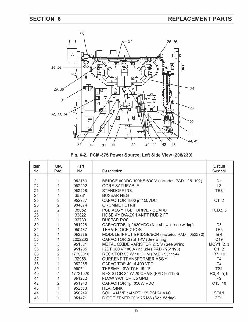
SECTION 6 REPLACEMENT PARTS
45
INSTRUCTION MANUAL CHANGES
The "A" edition (2/98) of this manual covers the following changes:
1. Each replacement IGBT and bridge module now include the appropriate thermal pad.
The "B" edition (9/98) of this manual covers the following changes:
1. Added mechanized cutting installation using PT-20AM torch with the PCM-875.
2. Deleted discontinued L-TEC packages and parts.
The "C" edition (2/02) of this manual covers the following changes:
1. Revises Figure 3-3 to show the changes made to the electrode.
2. Revises Figure 4-1 to show the removal of the Valve Pin which is no longer a part of the PT-27 Torch.
3. The hi frequency gap is changed from "between .027 and .033" to "set to .040". (See page 23, Section E, Step3).
The "D" edition (10/2006) of this manual covers the following changes:
1. Incorporated inputs from Charles Aimar on Pages 12, 14 and 31.
The "E" edition (07/2007) of this manual covers the following changes:
1. Added updated Disclaimer page after front cover.

+.

F15-335-E 07/2007 Printed in U.S.A.
IF YOU DO NOT KNOW WHOM TO CALL
Telephone: (800) ESAB-123/ Fax: (843) 664-4452/ Web:http://www.esab.com
Hours: 7:30 AM to 5:00 PM EST
A. CUSTOMER SERVICE QUESTIONS:Order Entry Product Availability Pricing DeliveryOrder Changes Saleable Goods Returns Shipping Information
Eastern Distribution Center Telephone: (800)362-7080 / Fax: (800) 634-7548
Central Distribution Center Telephone: (800)783-5360 / Fax: (800) 783-5362
Western Distribution Center Telephone: (800) 235-4012/ Fax: (888) 586-4670
B. ENGINEERING SERVICE: Telephone: (843) 664-4416 / Fax : (800) 446-5693Welding Equipment Troubleshooting Hours: 7:30 AM to 5:00 PM ESTWarranty Returns Authorized Repair Stations
C. TECHNICAL SERVICE: Telephone: (800) ESAB-123/ Fax: (843) 664-4452Part Numbers Technical Applications Hours: 8:00 AM to 5:00 PM ESTPerformance Features Technical Specifications Equipment Recommendations
D. LITERATURE REQUESTS: Telephone: (843) 664-5562 / Fax: (843) 664-5548Hours: 7:30 AM to 4:00 PM EST
E. WELDING EQUIPMENT REPAIRS: Telephone: (843) 664-4487 / Fax: (843) 664-5557Repair Estimates Repair Status Hours: 7:30 AM to 3:30 PM EST
F. WELDING EQUIPMENT TRAINING:Telephone: (843)664-4428 / Fax: (843) 679-5864Training School Information and Registrations Hours: 7:30 AM to 4:00 PM EST
G. WELDING PROCESS ASSISTANCE:Telephone: (800) ESAB-123 Hours: 7:30 AM to 4:00 PM EST
H. TECHNICAL ASST. CONSUMABLES:Telephone : (800) 933-7070 Hours: 7:30 AM to 5:00 PM EST
ESAB Welding & Cutting Products, Florence, SC Welding EquipmentCOMMUNICATION GUIDE - CUSTOMER SERVICES


