
Parametric Study of the Ignition of Metal Powders by Electric Spark
Graduate Mentor: Ervin Beloni
Faculty Mentor: Prof. Edward Dreizin
Bhavita Patel
July 6th 2008

Background: Metals as Fuel Additives
• Aluminum, other metals used as
fuel additives
– Example: Propellants, explosives,
pyrotechnics
• Advantages of Metals: high energy
density
• Shortcomings of Metals:
– relatively low reaction rates
New Approaches
• New approaches to increase reaction rate:
• Synthesis can be done by:
•Mechanically alloyed powders
•Reactive nanocomposites
• By using new approaches the Reactivity increased
• But, Sensitivity increases as well
Sensitivity needs to be decreased
Sensitivity needs to be understood

Electro-Static Discharge (ESD) for Sensitivity Testing
• The ESD testing are based on US Bureau of Mines Report from 1940s.
• Part of current MIL-STD-1751A/NATO-AOP-7, this is the standard followed by many countries for such ESD testing.
• ESD offers a qualitative ranking of ESD sensitivity between different powders by comparing Minimum Ignition Energy (MIE)
Skinner, D., Olson, D., Block-Bolton, A. “Electrostatic Discharge Ignition of Energetic Materials” Propellants, Explosives, Pyrotechnics 23, pp. 34-42 (1997)
Magnesium (Mg)
Powder Ignited
Pin Electrode
Sample Cup
ESD Ignition: Current Issues
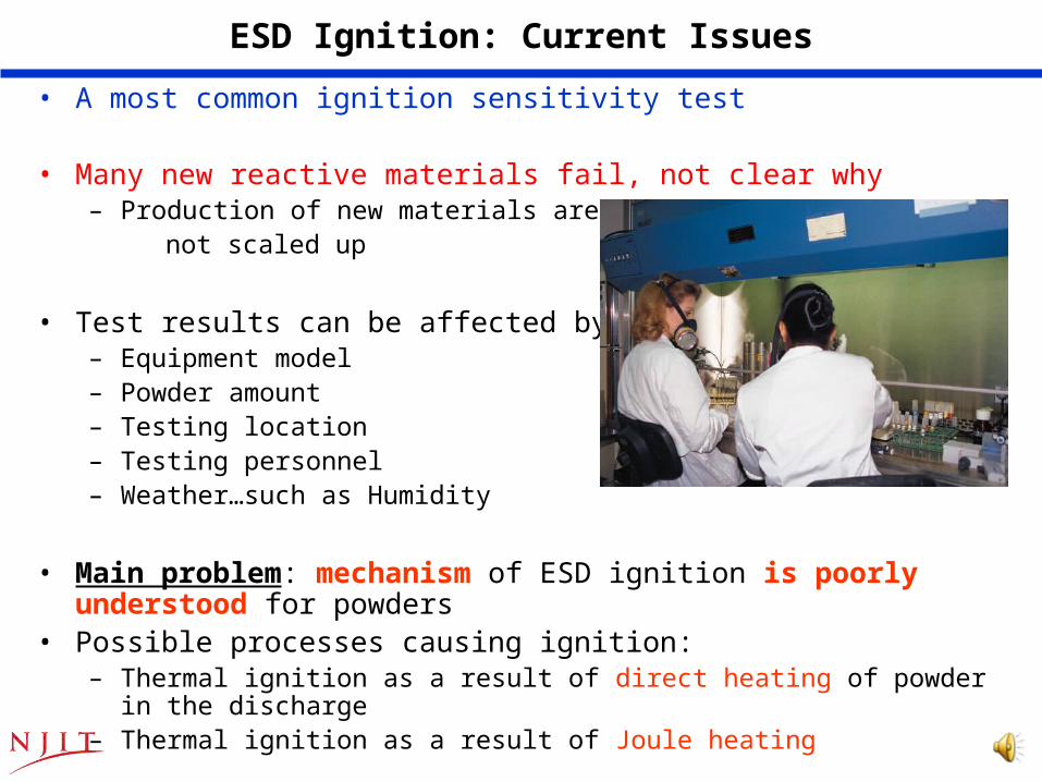
• A most common ignition sensitivity test
• Many new reactive materials fail, not clear why– Production of new materials are not scaled up
• Test results can be affected by– Equipment model– Powder amount– Testing location– Testing personnel– Weather…such as Humidity
• Main problem: mechanism of ESD ignition is poorly understood for powders
• Possible processes causing ignition:– Thermal ignition as a result of direct heating of powder in the discharge– Thermal ignition as a result of Joule heating
Technical Approach
• Perform an experimental parametric study
• Determine how ignition is affected by the process parameters
• Establish a model that can adequately describe
experiments
– Different ignition mechanisms are expected to result in different effect of discharge parameters on ignition
• Challenge: design a parametric study to produce meaningful results

Basic Setup for ESD Testing
• Free powder placed in an electrode cup• Capacitor charged to a specific voltage• Capacitor discharges through pin electrode to powder bed• Pulse parameters
– Voltage, duration, current, overall energy
Powder bedDCHigh Voltage
CapacitorVoltageSwitch 1 Switch 2
Pin Electrode
Distance (Gap)

Setting of a Parametric Study
• How is ignition affected by?
– Material
• Magnesium & Aluminum
– Particle size
• Spherical Mg 10.3 µm
• Spherical Al 3.0 - 4.5 µm
• Spherical Al 4.5 - 7.0 µm
– Applied energy (capacitance & voltage)
• 2000 pF, 5000pF, 10000pF, etc.
– Applied voltage
• 8kV, 10 kV, 12kV, 16kV, etc.
– Pulse duration (Capacitance & Resistance)
– Spark Configuration (gap)
• Output: optical trace
(emission from ignited powder)
– Measure ignition delay time (
the Delay time measured from the
Spark to the increasing slope)
– Other optical measurements to be
considered in the future (spectral,
intensity, etc.)

Experimental Setup with Diagnostics
DC High Voltage Power Supply
Resistor/Capacitor Selector
Spectrometer
Chromel Wire
Oscilloscope
PMT 1
PMT 2
Pin Electrode
Fiber Optics
Sample Cup
Firing Test System
Interference Filters
Voltage Inductance
Coil Current Inductance
Coil
Switch
Cup diameter: 6 mm
Cup depth: 0.45 mm
Voltage Inductance Coil: 1 V = 1 A
Current Inductance Coil: 1 V = 10 A

Outline of Experiments Conducted
• Powders
– Spherical Mg 10.3 µm
– Spherical Al 3.0 - 4.5 µm
– Spherical Al 4.5 - 7.0 µm
• Test Al powders at 8 kV– Capacitances
• 2000pF (Does not Ignite)• 5000 pF• 10000 pF
– Gap• 0.2 mm• 1.5 mm
– Resistance• 0 Ω
• Vary voltage at a given
capacitance
• Repeat same experiments for Al
powders and Mg powder with
smaller weight.
• From each set of runs determine
– Ignition delay
– Spark energy
Aluminum Powder

Size Distribution for Mg and Al
Partical size (µm)0.1 1 10 100
Volu
me %
Mg 10.3 µm
Al (3.0-4.5) µm
Al (4.5-7.0) µm

Processing of Current and Voltage
Time, µs0 1 2 3 4 5 6
Cur
rent
, A; V
olta
ge, V
-400
-200
0
200
400
600 Current-Voltage-traces
Experimental currentFit currentExperimental voltage
2
22 2
2 1sin exp
4 24ACV R R
I t t tLC L LLC R C
E IV t

Emission Traces of ALS
hort
Sig
nal (
V)
0
1
2
3
4
5
6
-1
Time (s)0.00 0.01 0.02 0.03 0.04 0.05 0.06 0.07
-1
0
1
2
3
4
5
Spark
Spark
Shorter Ignition Delay
Longer Ignition Delay

Processing of Delay PulseE
mis
sion
sig
nal,
V
0
1
2
3
4
5
6 Raw Derivative
Time, ms
9.0 9.5 10.0 10.5 11.0 11.5 12.0
Der
ivat
ive,
V/s
0
500
1000
1500
Ignition delay
Zero-level signal
Spark
First peakof the signal derivative
Slope at the peak of the derivative

Ignition Delay v Energy for Mg powder
Measured Spark Energy (mJ)
0 20 40 60 80 100 120
Ign
itio
n D
ela
y (
ms
)
0.0
0.5
1.0
1.5
2.0
2.5
3.0Recovered2
2000 pF - 0.2 mm - (6 - 16 kV, in 2 kV steps)5000 pF - 0.2 mm - 8 kV10000 pF - 0.2 mm - 8 kV2000 pF - 1.5 mm - 8 kV5000 pF - 1.5 mm - 8 kV10000 pF - 1.5 mm - 8 kV

Ignition Delay v Energy for Al
0 20 40 60 80 100 120 140
Ign
itio
n D
ela
y (
ms)
0
2
4
6
8
10
Measured Spark Energy (mJ)
Al (3.0-4.5) m 10000pF-0.2mm-8kVAl (3.0-4.5) m 5000pF-0.2mm-8kVAl (3.0-4.5) m 10000pF-1.5mm-8kVAl (3.0-4.5) m 5000pF-1.5mm-8kVAl (4.5-7.0) m 10000pF-0.2mm-8kVAl (4.5-7.0) m 5000pF-0.2mm-8kVAl (4.5-7.0) m 10000pF-1.5mm-8kVAl (4.5-7.0) m 5000pF-1.5mm-8kV

Summary / Future Work
SUMMARY:• For Mg powder: ignition delay is a function of energy
– Shorter delays at higher spark energies– Ignition delays do not decrease below about 0.5 ms
• For Al powders: ignition delay is a function of particle size– Shorter delay for finer particles– No detectable effect of energy– Larger error bars compared to Mg results: explained by a more
difficult ignition FUTURE WORK:• Reprocess data to attempt reducing the error bars.
– Using another criterion to analyze previous data: by choosing some threshold value that is above the base signal noise.
• Additional experiments with new materials, varied settings


![Mentor Team Program [name of home] Mentor Team Program [name of home] Mentor Team Program](https://cdn.vdocuments.site/doc/165x107/56649e0b5503460f94af301b/mentor-team-program-name-of-home-mentor-team-program-name-of-home-mentor.jpg)

