DEIF A/S · Frisenborgvej 33 · DK-7800 Skive · Tel.: +45 9614 9614 · Fax: +45 9614 9615 · [email protected] · www.deif.com
DEIF A/S · Frisenborgvej 33 · DK-7800 Skive · Tel.: +45 9614 9614 · Fax: +45 9614 9615 · [email protected] · www.deif.com
DEIF A/S · Frisenborgvej 33 · DK-7800 Skive · Tel.: +45 9614 9614 · Fax: +45 9614 9615 · [email protected] · www.deif.com
OPERATOR'S MANUAL
Generator Paralleling Controller, GPC-3 -Generator Protection Unit, GPU-3/GPU-3 Hydro -
Paralleling and Protection Unit, PPU● Display and push-button functions● Alarm handling● Log list
Document no.: 4189340579DSW version: 3.0X.X
1. General information1.1. Warnings, legal information and safety..................................................................................................3
1.1.1. Warnings and notes ......................................................................................................................31.1.2. Legal information and disclaimer ..................................................................................................31.1.3. Safety issues ................................................................................................................................31.1.4. Electrostatic discharge awareness ...............................................................................................31.1.5. Factory settings ............................................................................................................................3
1.2. About the Operator's Manual..................................................................................................................41.2.1. General purpose ...........................................................................................................................41.2.2. Intended users ..............................................................................................................................41.2.3. Contents and overall structure ......................................................................................................4
2. Display unit2.1. General...................................................................................................................................................52.2. Display (DU-2) layouts...........................................................................................................................5
2.2.1. GPC...............................................................................................................................................52.2.2. GPU...............................................................................................................................................72.2.3. GPU Hydro....................................................................................................................................82.2.4. PPU...............................................................................................................................................9
2.3. Display push-buttons and LEDs...........................................................................................................102.3.1. Push-button functions..................................................................................................................102.3.2. LED functions..............................................................................................................................11
2.4. Lamp test and dimmer functions..........................................................................................................122.4.1. Lamp test.....................................................................................................................................122.4.2. Dimmer function...........................................................................................................................122.4.3. AOP-2 lamp test and dimmer function.........................................................................................13
3. Menu systems and structure3.1. Display menu systems.........................................................................................................................143.2. Menu structure.....................................................................................................................................14
3.2.1. Entry window...............................................................................................................................143.2.2. View menu...................................................................................................................................153.2.3. View menu navigation..................................................................................................................153.2.4. Setup menu.................................................................................................................................16
3.3. Display texts.........................................................................................................................................183.3.1. Information texts..........................................................................................................................183.3.2. Status texts..................................................................................................................................19
3.4. Unit operation modes and password....................................................................................................203.4.1. Mode overview.............................................................................................................................203.4.2. Mode selection.............................................................................................................................203.4.3. Password.....................................................................................................................................20
4. Alarm handling and log list4.1. Alarm handling.....................................................................................................................................234.2. Log list..................................................................................................................................................23
5. Service menu5.1. Purpose of the service menu................................................................................................................265.2. Entry window........................................................................................................................................26
6. Parameter setup6.1. Procedures for setup............................................................................................................................286.2. Finding the selected parameter............................................................................................................286.3. Parameter descriptions........................................................................................................................286.4. Setup....................................................................................................................................................29
ML-2 operators manual 4189340579 UK
DEIF A/S Page 2 of 29

1. General information1.1 Warnings, legal information and safety
1.1.1 Warnings and notesThroughout this document, a number of warnings and notes with helpful user information will be presented.To ensure that these are noticed, they will be highlighted as follows in order to separate them from the gener-al text.
Warnings
Warnings indicate a potentially dangerous situation, which could result in death, personal in-jury or damaged equipment, if certain guidelines are not followed.
Notes
Notes provide general information, which will be helpful for the reader to bear in mind.
1.1.2 Legal information and disclaimerDEIF takes no responsibility for installation or operation of the generator set. If there is any doubt about howto install or operate the engine/generator controlled by the Multi-line 2 unit, the company responsible for theinstallation or the operation of the set must be contacted.
The Multi-line 2 unit is not to be opened by unauthorised personnel. If opened anyway, the war-ranty will be lost.
DisclaimerDEIF A/S reserves the right to change any of the contents of this document without prior notice.
1.1.3 Safety issuesInstalling and operating the Multi-line 2 unit may imply work with dangerous currents and voltages. Therefore,the installation should only be carried out by authorised personnel who understand the risks involved in work-ing with live electrical equipment.
Be aware of the hazardous live currents and voltages. Do not touch any AC measurement in-puts as this could lead to injury or death.
1.1.4 Electrostatic discharge awarenessSufficient care must be taken to protect the terminal against static discharges during the installation. Once theunit is installed and connected, these precautions are no longer necessary.
1.1.5 Factory settingsThe Multi-line 2 unit is delivered from factory with certain factory settings. These are based on average valuesand are not necessarily the correct settings for matching the engine/generator set in question. Precautionsmust be taken to check the settings before running the engine/generator set.
ML-2 operators manual 4189340579 UK General information
DEIF A/S Page 3 of 29

1.2 About the Operator's Manual
1.2.1 General purposeThis Operator's Manual mainly includes general product information, display readings, push-button and LEDfunctions, alarm handling descriptions and presentation of the log list.
The general purpose of this document is to give the operator important information to be used in the dailyoperation of the unit.
Please make sure to read this document before starting to work with the Multi-line 2 unit andthe generator set to be controlled. Failure to do this could result in human injury or damage tothe equipment.
1.2.2 Intended usersThis Operator's Manual is mainly intended for the daily user. On the basis of this document, the operator willbe able to carry out simple procedures such as start/stop and control of the generator set.
1.2.3 Contents and overall structureThis document is divided into chapters, and in order to make the structure simple and easy to use, eachchapter will begin from the top of a new page.
ML-2 operators manual 4189340579 UK General information
DEIF A/S Page 4 of 29
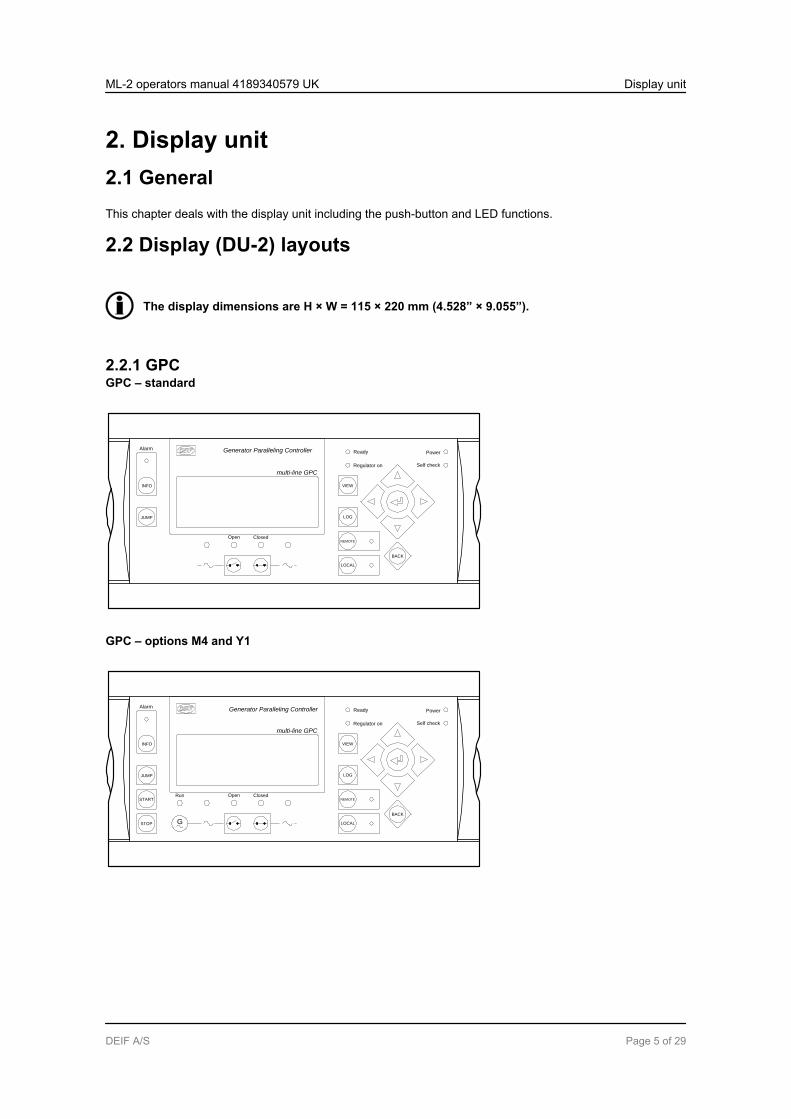
2. Display unit2.1 GeneralThis chapter deals with the display unit including the push-button and LED functions.
2.2 Display (DU-2) layouts
The display dimensions are H × W = 115 × 220 mm (4.528” × 9.055”).
2.2.1 GPCGPC – standard
Generator Paralleling Controller
multi-line GPC
Self check
Ready
Regulator on
JUMP
INFO
Alarm
VIEW
LOG
REMOTE
LOCAL
BACK
Open Closed
Power
GPC – options M4 and Y1
Generator Paralleling Controller
multi-line GPC
Self check
Ready
Regulator on
JUMP
START
INFO
STOP
Alarm
VIEW
LOG
REMOTE
LOCAL
BACK
G
Open ClosedRun
Power
ML-2 operators manual 4189340579 UK Display unit
DEIF A/S Page 5 of 29
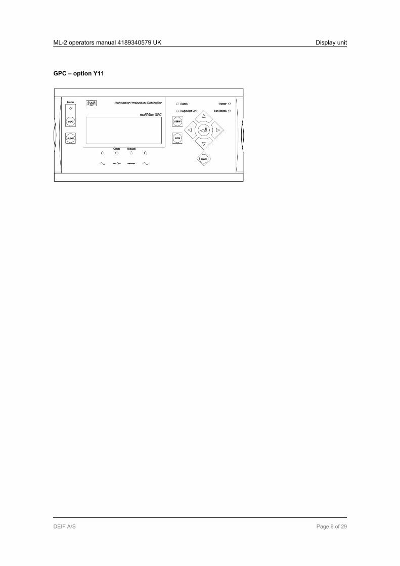
GPC – option Y11
ML-2 operators manual 4189340579 UK Display unit
DEIF A/S Page 6 of 29

2.2.2 GPUGPU – standard
Generator Protection Unit
multi-line GPU
Self check
Ready
JUMP
INFO
Alarm
VIEW
LOG
BACK
Power
GPU – options G2 and Y5
Generator Protection Unit
multi-line GPU
Self check
Ready
Regulator on
JUMP
INFO
Alarm
VIEW
LOG
REMOTE
LOCAL
BACK
Open Closed
Power
GPU – options M4 and Y7
Generator Protection Unit
multi-line GPU
Self check
Ready
JUMP
START
INFO
STOP
Alarm
VIEW
LOG
REMOTE
LOCAL
BACK
G
Run
Power
ML-2 operators manual 4189340579 UK Display unit
DEIF A/S Page 7 of 29

GPU – options G2, M4 and Y1
Generator Protection Unit
multi-line GPU
Self check
Ready
Regulator on
JUMP
START
INFO
STOP
Alarm
VIEW
LOG
REMOTE
LOCAL
BACK
G
Open ClosedRun
Power
2.2.3 GPU HydroGPU Hydro – standard
Generator Protection Unit
multi-line GPU Hydro
Self check
Ready
JUMP
INFO
Alarm
VIEW
LOG
BACK
Power
GPU Hydro – options G2 and Y5
Generator Protection Unit
multi-line GPU Hydro
Self check
Ready
Regulator on
JUMP
INFO
Alarm
VIEW
LOG
REMOTE
LOCAL
BACK
Open Closed
Power
ML-2 operators manual 4189340579 UK Display unit
DEIF A/S Page 8 of 29
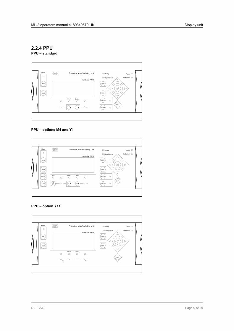
2.2.4 PPUPPU – standard
Protection and Paralleling Unit
multi-line PPU
Self check
Ready
Regulator on
JUMP
INFO
Alarm
VIEW
LOG
REMOTE
LOCAL
BACK
Open Closed
Power
PPU – options M4 and Y1
Protection and Paralleling Unit
multi-line PPU
Self check
Ready
Regulator on
JUMP
START
INFO
STOP
Alarm
VIEW
LOG
REMOTE
LOCAL
BACK
G
Open ClosedRun
Power
PPU – option Y11
Protection and Paralleling Unit
multi-line PPU
Self check
Ready
Regulator on
JUMP
INFO
Alarm
VIEW
LOG
BACK
Open Closed
Power
ML-2 operators manual 4189340579 UK Display unit
DEIF A/S Page 9 of 29
2.3 Display push-buttons and LEDs
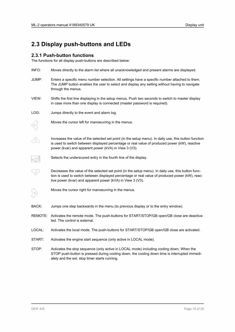
2.3.1 Push-button functionsThe functions for all display push-buttons are described below:
INFO: Moves directly to the alarm list where all unacknowledged and present alarms are displayed.
JUMP: Enters a specific menu number selection. All settings have a specific number attached to them.The JUMP button enables the user to select and display any setting without having to navigatethrough the menus.
VIEW: Shifts the first line displaying in the setup menus. Push two seconds to switch to master displayin case more than one display is connected (master password is required).
LOG: Jumps directly to the event and alarm log.
Moves the cursor left for manoeuvring in the menus.
Increases the value of the selected set point (in the setup menu). In daily use, this button functionis used to switch between displayed percentage or real value of produced power (kW), reactivepower (kvar) and apparent power (kVA) in View 3 (V3).
Selects the underscored entry in the fourth line of the display.
Decreases the value of the selected set point (in the setup menu). In daily use, this button func-tion is used to switch between displayed percentage or real value of produced power (kW), reac-tive power (kvar) and apparent power (kVA) in View 3 (V3).
Moves the cursor right for manoeuvring in the menus.
BACK: Jumps one step backwards in the menu (to previous display or to the entry window).
REMOTE: Activates the remote mode. The push-buttons for START/STOP/GB open/GB close are deactiva-ted. The control is external.
LOCAL: Activates the local mode. The push-buttons for START/STOP/GB open/GB close are activated.
START: Activates the engine start sequence (only active in LOCAL mode).
STOP: Activates the stop sequence (only active in LOCAL mode) including cooling down. When theSTOP push-button is pressed during cooling down, the cooling down time is interrupted immedi-ately and the ext. stop timer starts running.
ML-2 operators manual 4189340579 UK Display unit
DEIF A/S Page 10 of 29
2.3.2 LED functionsEach LED located on the display has its own function. The colour is green, red or yellow (fixed or flashing)dependent on its function. The functions for all display LEDs are described below:
Alarm: LED red flashing indicates that unacknowledged alarms are present.LED red fixed light indicates that ALL alarms are acknowledged, but one or more alarms arestill present.LED off when no alarm is present.
Run: LED yellow when a running feedback failure is active. (G V/Hz OK, but no running feed-back).LED green indicates that the generator is running and the voltage and frequency are OK.LED off when no running feedback and no voltage and frequency are measured.
G V/Hz (~): LED yellow when the DG is running and V/Hz not OK.LED green when the DG is running and the V/Hz OK timer has expired.
Open: LED red when the breaker is tripped by a protection function.LED yellow when the breaker is deloaded.LED green when the breaker is open.LED off when the breaker is closed.
Closed: LED yellow indicates that the synchronisation function is active.LED green when the breaker is closed.LED off when the breaker is open.
BB V/Hz (~): LED green when BB V/Hz OK.LED yellow when BB V/Hz not OK.LED red when BB voltage is zero (dead bus).
Ready: LED green when the unit is ready for operation.LED off when the unit is not ready (for example, the start enable is not activated or an activeblock, trip or shutdown alarm is present).
This indication is to tell the user whether the controller (not the engine) is ready or not.
Regulator ON: LED green when the regulator is activated.LED off when the regulator is off.
Remote: LED green when remote mode is active.LED off when local or SWBD mode is active.
Local: LED green when local mode is active.LED off when remote or SWBD mode is active.
Power: LED green indicates that the auxiliary supply is switched on.
Self check: LED green indicates that the unit is OK.
ML-2 operators manual 4189340579 UK Display unit
DEIF A/S Page 11 of 29
2.4 Lamp test and dimmer functions
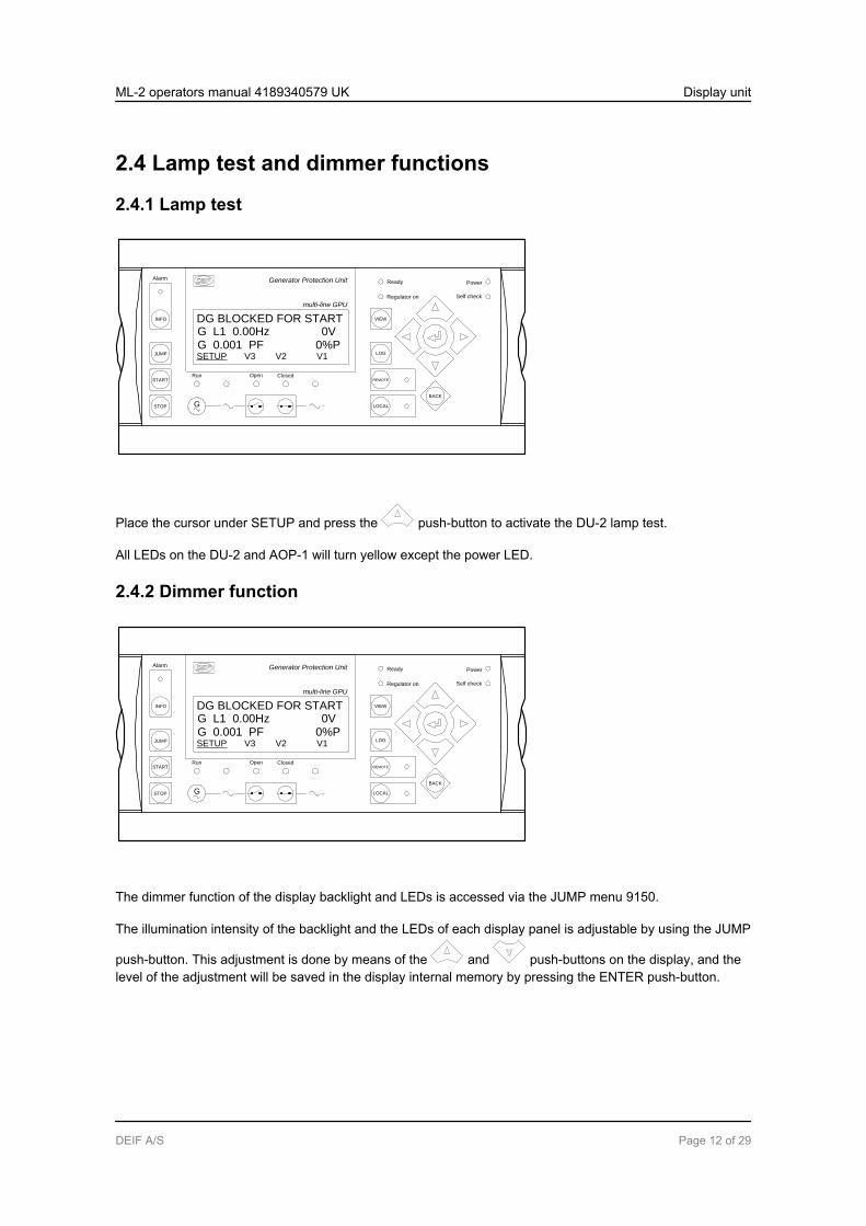
2.4.1 Lamp test
Generator Protection Unit
multi-line GPU
Self check
Ready
Regulator on
JUMP
START
INFO
STOP
Alarm
VIEW
LOG
REMOTE
LOCAL
BACK
G
Open ClosedRun
Power
G 0.001 PF 0%PSETUP V3 V2 V1
DG BLOCKED FOR STARTG L1 0.00Hz 0V
Place the cursor under SETUP and press the push-button to activate the DU-2 lamp test.
All LEDs on the DU-2 and AOP-1 will turn yellow except the power LED.
2.4.2 Dimmer function
Generator Protection Unit
multi-line GPU
Self check
Ready
Regulator on
JUMP
START
INFO
STOP
Alarm
VIEW
LOG
REMOTE
LOCAL
BACK
G
Open ClosedRun
Power
G 0.001 PF 0%PSETUP V3 V2 V1
DG BLOCKED FOR STARTG L1 0.00Hz 0V
The dimmer function of the display backlight and LEDs is accessed via the JUMP menu 9150.
The illumination intensity of the backlight and the LEDs of each display panel is adjustable by using the JUMP
push-button. This adjustment is done by means of the and push-buttons on the display, and thelevel of the adjustment will be saved in the display internal memory by pressing the ENTER push-button.
ML-2 operators manual 4189340579 UK Display unit
DEIF A/S Page 12 of 29

2.4.3 AOP-2 lamp test and dimmer function
AOP-2
1
The AOP-2 has a separate push-button (1) for the combined lamp test and dimmer functionality. A short acti-vation of the push-button will activate the lamp test function. If no further action is taken within three seconds,the AOP-2 will turn back to normal indication.
To activate the dimmer function, the push-button must be pressed several times or continuously to reach thedesired light intensity.
ML-2 operators manual 4189340579 UK Display unit
DEIF A/S Page 13 of 29

3. Menu systems and structure3.1 Display menu systemsThe display includes two menu systems which can be used without password entry:
View menu systemThis is the commonly used menu system. 15 windows are configurable and can be entered by using the ar-row push-buttons.
Setup menu systemThis menu system is used to set up the unit, and if the user needs detailed information that is not available inthe view menu system. Changing of parameter settings is password protected.
3.2 Menu structure
3.2.1 Entry windowWhen the unit is powered up, an entry window appears. The entry window is the gateway to the other menus.It can always be reached by pressing the BACK push-button three times.
The event and alarm list will appear at power up, if an alarm is present.
Paralleling and Protection Unit
multi-line PPU
G 0.001 PF 0%PSETUP V3 V2 V1
DG BLOCKED FOR STARTG L1 0.00Hz 0V
ML-2 operators manual 4189340579 UK Menu systems and structure
DEIF A/S Page 14 of 29
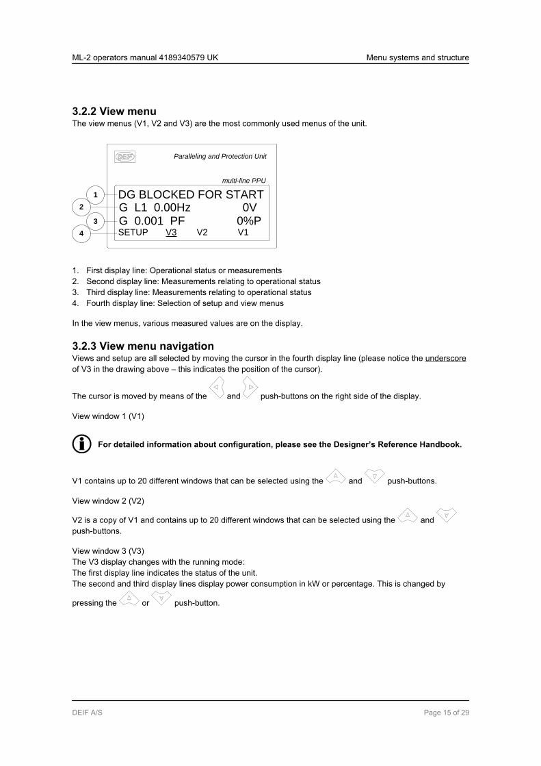
3.2.2 View menuThe view menus (V1, V2 and V3) are the most commonly used menus of the unit.
Paralleling and Protection Unit
multi-line PPU
G 0.001 PF 0%PSETUP V3 V2 V1
DG BLOCKED FOR STARTG L1 0.00Hz 0V
1
2
3
4
1. First display line: Operational status or measurements2. Second display line: Measurements relating to operational status3. Third display line: Measurements relating to operational status4. Fourth display line: Selection of setup and view menus
In the view menus, various measured values are on the display.
3.2.3 View menu navigationViews and setup are all selected by moving the cursor in the fourth display line (please notice the underscoreof V3 in the drawing above – this indicates the position of the cursor).
The cursor is moved by means of the and push-buttons on the right side of the display.
View window 1 (V1)
For detailed information about configuration, please see the Designer’s Reference Handbook.
V1 contains up to 20 different windows that can be selected using the and push-buttons.
View window 2 (V2)
V2 is a copy of V1 and contains up to 20 different windows that can be selected using the and push-buttons.
View window 3 (V3)The V3 display changes with the running mode:The first display line indicates the status of the unit.The second and third display lines display power consumption in kW or percentage. This is changed by
pressing the or push-button.
ML-2 operators manual 4189340579 UK Menu systems and structure
DEIF A/S Page 15 of 29

3.2.4 Setup menuThe setup menu is used for parameter setup or to get detailed information that is not available in the viewmenu system. In this way, this menu can be used for both daily use and setup purposes. The menu is en-tered from the entry window by selecting the entry SETUP in the fourth display line.
Paralleling and Protection Unit
multi-line PPU
PROTECTION SETUPPROT CTRL I/O SYST
G 400 400 400VG f-L1 0.00Hz
1
2
3
4
First display line:(Daily use) The first line is used to display generator and busbar values
Second display line:(Daily use) Various values can be displayed(Menu system) Information about the selected channel number(Alarm/event list) The latest alarm/event is displayed
Third display line:(Daily use)(Setup menu)
Explanation for the fourth line cursor selection presents setting of the selected function,and if changes are made, the possible max. and min. values for the setting
Fourth display line:(Daily use) Entry selection for the setup menu
Press SELECT to select the underscored menu(Setup menu) Sub-functions for the individual parameters, for example limit
ML-2 operators manual 4189340579 UK Menu systems and structure
DEIF A/S Page 16 of 29
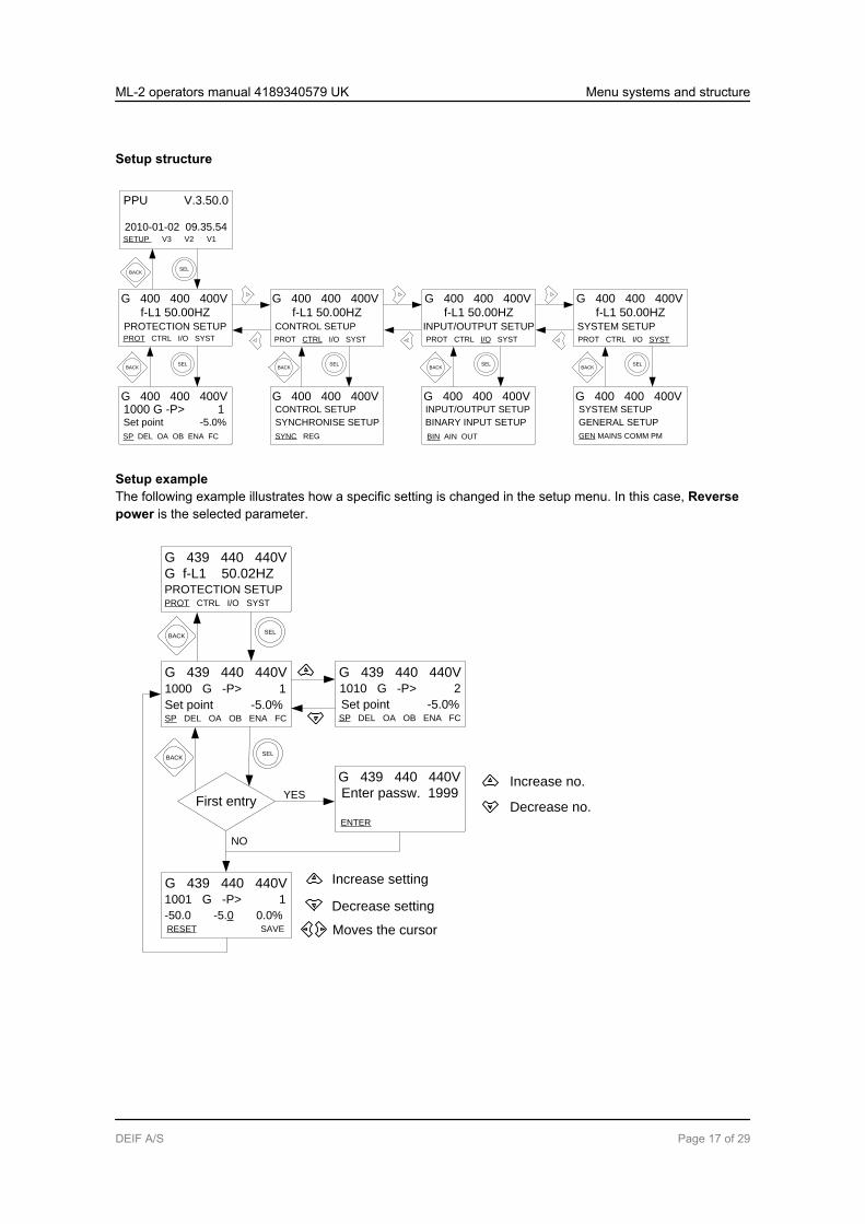
Setup structure
SELBACK
SELBACK
SP DEL OA OB ENA FC
1000 G -P> 1Set point -5.0%
G 400 400 400V
SYNC REG
CONTROL SETUP
SYNCHRONISE SETUP
G 400 400 400V
BIN AIN OUT
INPUT/OUTPUT SETUP
BINARY INPUT SETUP
G 400 400 400V
GEN MAINS COMM PM
SYSTEM SETUP
GENERAL SETUP
G 400 400 400V
f-L1 50.00HZSYSTEM SETUP
G 400 400 400V
PROT CTRL I/O SYST
f-L1 50.00HZINPUT/OUTPUT SETUP
G 400 400 400V
PROT CTRL I/O SYSTPROT CTRL I/O SYST
G 400 400 400Vf-L1 50.00HZ
CONTROL SETUP
PROT CTRL I/O SYST
G 400 400 400Vf-L1 50.00HZ
PROTECTION SETUP
2010-01-02 09.35.54SETUP V3 V2 V1
PPU V.3.50.0
SELBACK
SELBACK
SELBACK
Setup exampleThe following example illustrates how a specific setting is changed in the setup menu. In this case, Reversepower is the selected parameter.
First entry
Increase no.
Decrease no.
Increase setting
Decrease setting
Moves the cursor
YES
NO
PROT CTRL I/O SYST
G 439 440 440V
G f-L1 50.02HZPROTECTION SETUP
SP DEL OA OB ENA FC
1000 G -P> 1
Set point -5.0%
G 439 440 440V
SP DEL OA OB ENA FC
1010 G -P> 2
Set point -5.0%
G 439 440 440V
ENTER
Enter passw. 1999
G 439 440 440V
RESET SAVE
1001 G -P> 1
-50.0 -5.0 0.0%
G 439 440 440V
BACKSEL
BACKSEL
ML-2 operators manual 4189340579 UK Menu systems and structure
DEIF A/S Page 17 of 29
3.3 Display texts
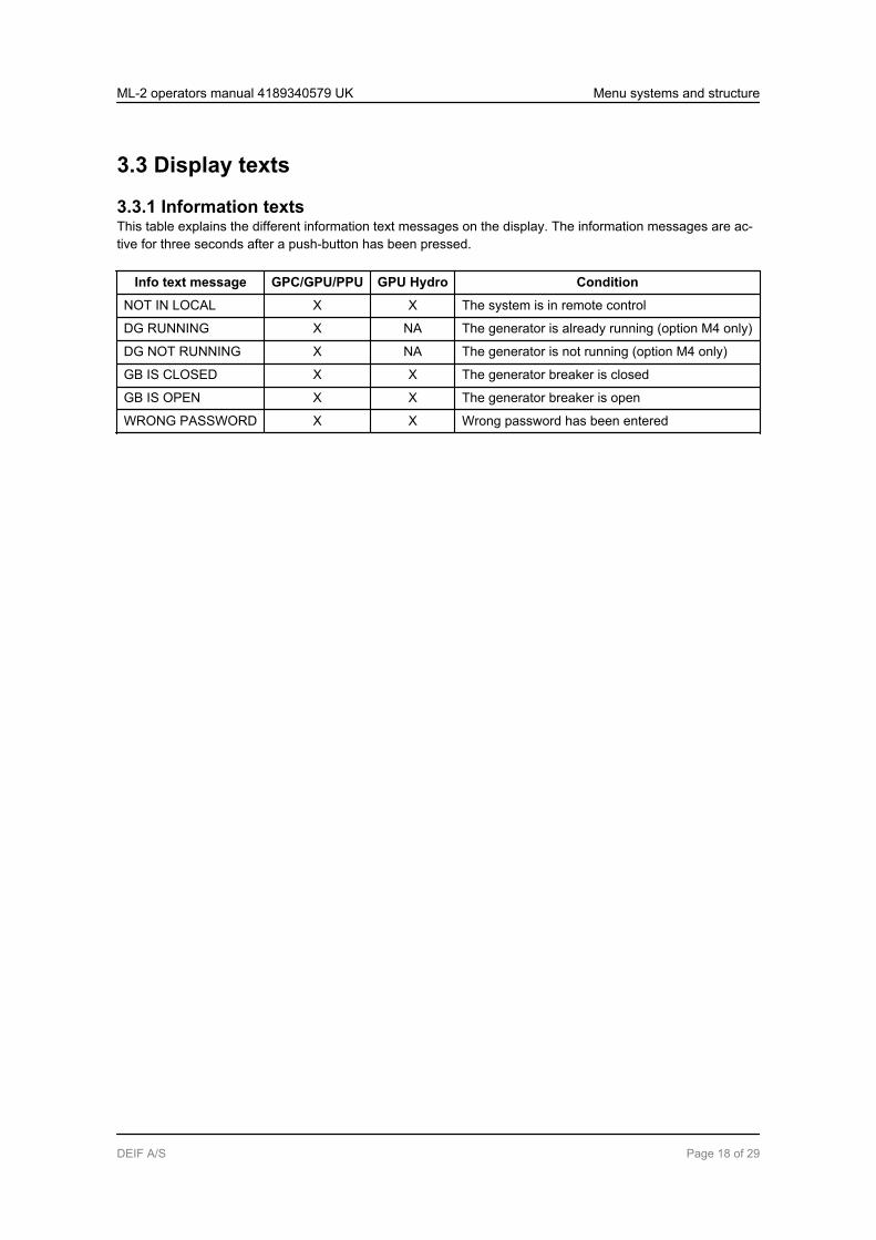
3.3.1 Information textsThis table explains the different information text messages on the display. The information messages are ac-tive for three seconds after a push-button has been pressed.
Info text message GPC/GPU/PPU GPU Hydro Condition
NOT IN LOCAL X X The system is in remote control
DG RUNNING X NA The generator is already running (option M4 only)
DG NOT RUNNING X NA The generator is not running (option M4 only)
GB IS CLOSED X X The generator breaker is closed
GB IS OPEN X X The generator breaker is open
WRONG PASSWORD X X Wrong password has been entered
ML-2 operators manual 4189340579 UK Menu systems and structure
DEIF A/S Page 18 of 29

3.3.2 Status textsThe following table explains the different status text messages in the display. Status messages are automati-cally shown during operation without the operator activating any push-buttons.
Status text GPC/PPU
GPU/GPU Hy-
dro
Condition
READY X X The generator is not running, and the unit is ready foroperation
NOT READY X X The generator is not running, and for example an active“Trip GB” or “Shutdown” alarm is blocking operation
MANUAL X X Regulation is in MANUAL mode
FIXED FREQUENCYINT.
X X Fixed frequency using internal set point
FIXED FREQUENCYEXT.
X X Fixed frequency using external set point
STATIC SYNC. X X Static synchronisation in progress
DYNAMIC SYNC. X X Dynamic synchronisation in progress
ASYNCHRONOUSSYNC.
X X Synchronising asynchronous generator
FIXED RPM X X Asynchronous generator - GB open and sync. not acti-vated
LOAD SHARING INT. X - Load sharing using internal set point
LOAD SHARING EXT. X - Load sharing using external set point
FIXED POWER INT. X - Fixed power using internal set point
FIXED POWER EXT. X - Fixed power using external set point
DROOP INT. X - Droop mode active using internal set point
DROOP EXT. X - Droop mode active using external set point
RAMP DOWN X - Deloading the genset before opening of the GB
RAMP TO ###kW X - Increasing or decreasing the load of the genset to aspecific set point
START PREPARE X X The start prepare relay is activated
START RELAY ON X X The start relay is activated
START RELAY OFF X X The start relay is deactivated during the start sequence
COOLING DOWN ###s X X Cooling down period is activated
GENSET STOPPING X X This info is shown when cooling down has finished
EXT. STOP T. ###s X X Extended stop time after the running signal has disap-peared
TOO SLOW 00<---------- X X Generator running too slow during synchronising
----------> 00 TOO FAST X X Generator running too fast during synchronising
SWBD CONTROL X X SWBD control input activated
ML-2 operators manual 4189340579 UK Menu systems and structure
DEIF A/S Page 19 of 29

Status text GPC/PPU
GPU/GPU Hy-
dro
Condition
U GEN too low X X Generator voltage is too low compared to the BB volt-age during synchronisation
U GEN too high X X Generator voltage is too high compared to the BB volt-age during synchronisation
PREPARING ETHER-NET
X X The TCP/IP connection is initialising
3.4 Unit operation modes and password
3.4.1 Mode overviewThe unit has two different operation modes and one switchboard (blocked) mode.
Mode Description
LOCAL ● The display push-buttons (START, STOP, GB ON, GB OFF) are active and can be used bythe operator.
● The regulators are also active, that is the speed control will bring the generator to nominalspeed upon start.
● When pushing a breaker button for closing, the unit will synchronise the breaker (if al-lowed).
RE-MOTE
● The display control push-buttons (START, STOP, GB ON, GB OFF) are disabled.● The genset can be controlled via the digital inputs, for example “Start sync./control”.
SWBD ● Display push-buttons are disabled. The generator can only be controlled using the switch-board.
● The protection functions are still active.● The regulators are not active, that is speed control has to take place from the switchboard.
3.4.2 Mode selectionThe mode selection is carried out using the LOCAL or REMOTE push-buttons on the display.
3.4.3 PasswordThe unit includes three password levels. All levels can be adjusted in the PC software.
Available password levels:
Password level Factory setting Access
Customer Service Master
Customer 2000 X
Service 2001 X X
Master 2002 X X X
A parameter cannot be entered with a password that is ranking too low, but the settings can be displayedwithout password entry.
ML-2 operators manual 4189340579 UK Menu systems and structure
DEIF A/S Page 20 of 29

Each parameter can be protected by a specific password level by means of the PC utility software. Enter theparameter to be configured and select the correct password level.
The password level can be found in the column “Level” in the parameter view.
ML-2 operators manual 4189340579 UK Menu systems and structure
DEIF A/S Page 21 of 29
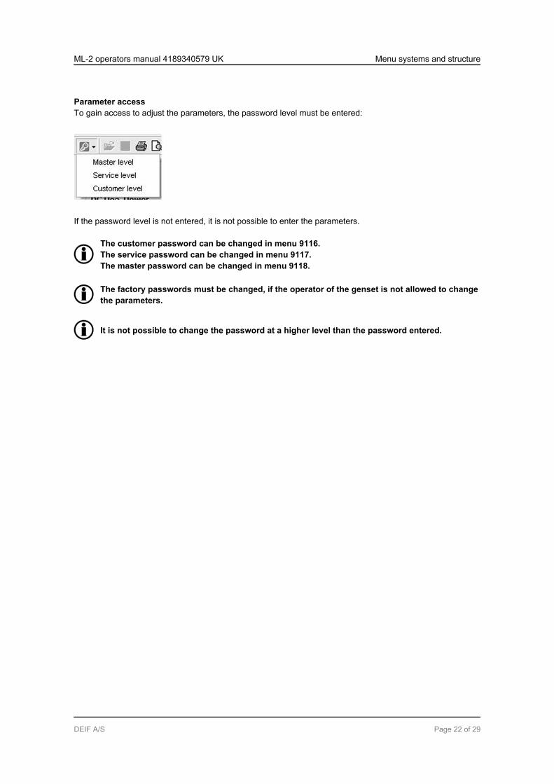
Parameter accessTo gain access to adjust the parameters, the password level must be entered:
If the password level is not entered, it is not possible to enter the parameters.
The customer password can be changed in menu 9116.The service password can be changed in menu 9117.The master password can be changed in menu 9118.
The factory passwords must be changed, if the operator of the genset is not allowed to changethe parameters.
It is not possible to change the password at a higher level than the password entered.
ML-2 operators manual 4189340579 UK Menu systems and structure
DEIF A/S Page 22 of 29
4. Alarm handling and log list4.1 Alarm handlingWhen an alarm occurs, the unit will automatically go to the alarm list for display of the alarm. This functioncan be disabled or enabled. For further explanation, please see the Designer’s Reference Handbook.
If you do not want to read the alarms, use the BACK push-button to exit the alarm list.
If you want to enter the alarm list later, use the INFO push-button to jump directly to the alarm list reading.
The alarm list contains both acknowledged and unacknowledged alarms, provided that they are still active(that is the alarm condition is still present). Once an alarm is acknowledged and the condition has disap-peared, the alarm will no longer be displayed in the alarm list.
This means that if there are no alarms, the alarm list will be empty.
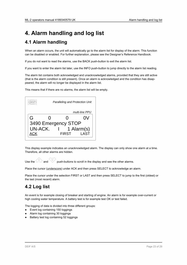
Paralleling and Protection Unit
multi-line PPU
UN-ACK. I 1 Alarm(s)ACK FIRST LAST
G 0 0 0V3490 Emergency STOP
This display example indicates an unacknowledged alarm. The display can only show one alarm at a time.Therefore, all other alarms are hidden.
Use the and push-buttons to scroll in the display and see the other alarms.
Place the cursor (underscore) under ACK and then press SELECT to acknowledge an alarm.
Place the cursor under the selection FIRST or LAST and then press SELECT to jump to the first (oldest) orthe last (most recent) alarm.
4.2 Log listAn event is for example closing of breaker and starting of engine. An alarm is for example over-current orhigh cooling water temperature. A battery test is for example test OK or test failed.
The logging of data is divided into three different groups:● Event log containing 150 loggings● Alarm log containing 30 loggings● Battery test log containing 52 loggings
ML-2 operators manual 4189340579 UK Alarm handling and log list
DEIF A/S Page 23 of 29

The logs can be viewed in the display or in the PC utility software. When the individual logs are full, each newevent will overwrite the oldest event according to the “first in – first out” principle.
DisplayWhen the LOG push-button is pressed, the display looks like this:
Paralleling and Protection Unit
multi-line PPU
EVENT LOGEVENT ALARM BATT.
G 400 400 400VLOG SETUP
Now it is possible to select one of the three logs.
If EVENT is selected, the log will look like this:
Paralleling and Protection Unit
multi-line PPU
2010-01-02 18:54:28.8INFO FIRST LAST
G 400 400 400VAck. alarm
The specific alarm or event is shown in the second line, and the time stamp is shown in the third line.
ML-2 operators manual 4189340579 UK Alarm handling and log list
DEIF A/S Page 24 of 29
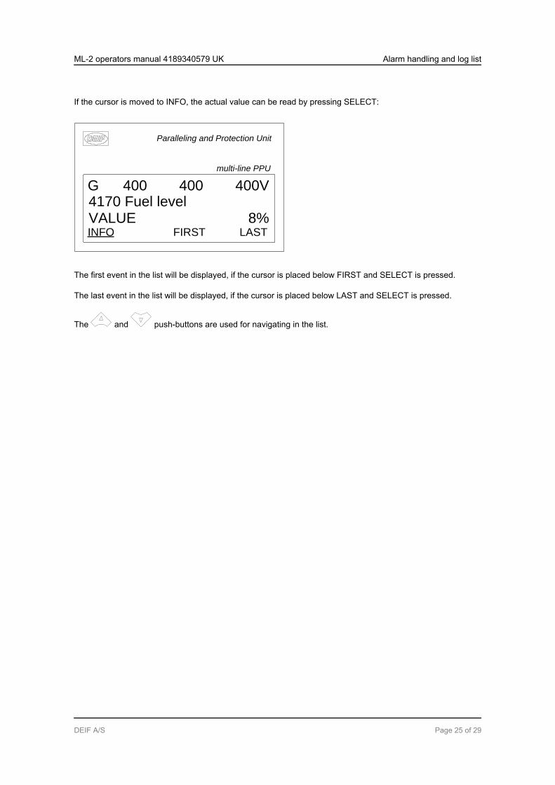
If the cursor is moved to INFO, the actual value can be read by pressing SELECT:
Paralleling and Protection Unit
multi-line PPU
VALUE 8%INFO FIRST LAST
G 400 400 400V4170 Fuel level
The first event in the list will be displayed, if the cursor is placed below FIRST and SELECT is pressed.
The last event in the list will be displayed, if the cursor is placed below LAST and SELECT is pressed.
The and push-buttons are used for navigating in the list.
ML-2 operators manual 4189340579 UK Alarm handling and log list
DEIF A/S Page 25 of 29
5. Service menu5.1 Purpose of the service menuThe purpose of the service menu is to give information about the present operating condition of the genset.The service menu is entered using the JUMP push-button and selecting menu 9120.
Use the service menu for easy troubleshooting in connection with the event log.
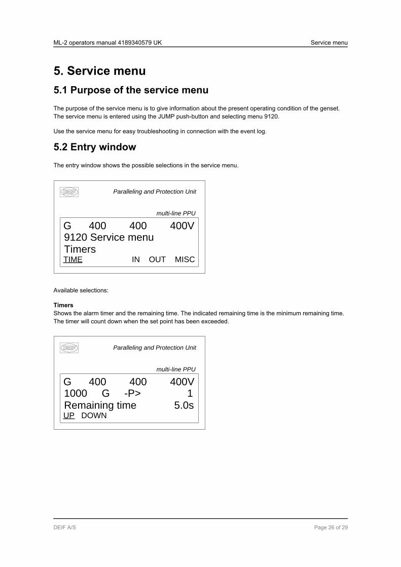
5.2 Entry windowThe entry window shows the possible selections in the service menu.
Paralleling and Protection Unit
multi-line PPU
TimersTIME IN OUT MISC
G 400 400 400V9120 Service menu
Available selections:
TimersShows the alarm timer and the remaining time. The indicated remaining time is the minimum remaining time.The timer will count down when the set point has been exceeded.
Paralleling and Protection Unit
multi-line PPU
Remaining time 5.0sUP DOWN
G 400 400 400V1000 G -P> 1
ML-2 operators manual 4189340579 UK Service menu
DEIF A/S Page 26 of 29

IN (digital input)Shows the status of the digital inputs.
Paralleling and Protection Unit
multi-line PPU
Input = 0UP DOWN
G 400 400 400VRunning
OUT (digital output)Shows the status of the digital outputs.
Paralleling and Protection Unit
multi-line PPU
Output = 0UP DOWN
G 400 400 400VHorn
MISC (miscellaneous)Shows miscellaneous messages.
Paralleling and Protection Unit
multi-line PPU
Various = 0UP DOWN
G 400 400 400VM-Logic enabled
ML-2 operators manual 4189340579 UK Service menu
DEIF A/S Page 27 of 29
6. Parameter setup6.1 Procedures for setup
The complete parameter list is presented in the separate Parameter List document of the Multi-line unit in question: GPC/GPC Gas/GPC Hydro/GPU Hydro document number 4189340580,GPU/GPU Gas/PPU document number 4189340581.
This chapter deals with the procedure to be followed when the parameters of the unit are set up from theinitial point of finding the individual parameter description to the actual setup. By use of various illustrations,the following will guide the user through the whole procedure of parameter setup step by step.
6.2 Finding the selected parameterThe first step in the parameter setup is to find the correct parameter descriptions. All parameter descriptionsin the Parameter List document are intended for reference purposes. The descriptions are structured accord-ing to their parameter titles and the main parameter group to which they belong.
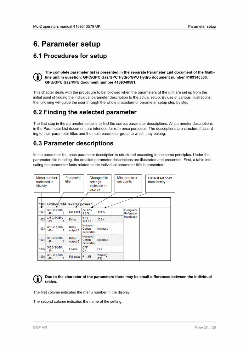
6.3 Parameter descriptionsIn the parameter list, each parameter description is structured according to the same principles. Under theparameter title heading, the detailed parameter descriptions are illustrated and presented. First, a table indi-cating the parameter facts related to the individual parameter title is presented:
Due to the character of the parameters there may be small differences between the individualtables.
The first column indicates the menu number in the display.
The second column indicates the name of the setting.
ML-2 operators manual 4189340579 UK Parameter setup
DEIF A/S Page 28 of 29

The third column describes the function of the parameter.
The fourth column indicates the minimum/maximum set point available for this setting.
The fifth column indicates the default set point of the unit from the factory. When it is necessary, additionalinformation will be supplied below the table in order to make the individual parameter descriptions as informa-tive as possible.
6.4 SetupAt this point of the process, the specific parameter description will have been located. Now, follow the menustructure presented earlier in this manual to set up the individual parameters. (In this overall example, wehave chosen to change the set point of the parameter 1000 G -P>).
Step 1: Enter the setup menu via SETUP in the fourth display line in the entry window.Step 2: Enter the protection menu via PROT in the fourth display line in the setup menu.Step 3:
Use the and push-buttons to locate the selected parameter.Step 4: Enter the set point menu via SP in the fourth display line.Step 5: Enter password to change the set point.Step 6:
Use the and push-buttons to increase/decrease the set point setting.Step 7: Move the “underscore” to save and press SEL; the new set point setting has now been saved.
ML-2 operators manual 4189340579 UK Parameter setup
DEIF A/S Page 29 of 29


