
Installation Guide
GFK-3185A
August 2020
PACMotion™ VFD Input/Output Chokes
(IP20 and IP66 Versions) INSTALLATION GUIDE

PACMotion VFD Input/Output Chokes Installation Guide Contents GFK-3185A August 2020
Contents i
Contents
Section 1: Important Safety Information ................................ 1
Section 2: Input Line Chokes .................................................. 2
2.1 Using Input Chokes .............................................................................................. 2
2.2 Dimensions – IP20 Single Phase Versions ............................................................. 2
2.3 Mounting Dimensions – IP66 Versions ................................................................. 4
2.4 Installation Schematic Diagram ........................................................................... 4
Section 3: Output Line Chokes ................................................ 5
3.1 Using Output Chokes........................................................................................... 5
3.2 Dimensions – Open Type ..................................................................................... 5
3.3 Mounting Dimensions – Enclosed Versions .......................................................... 6
3.4 Installation Schematic Diagram ........................................................................... 6
General Contact Information ......................................................................................... 7
Technical Support .......................................................................................................... 7

PACMotion VFD Input/Output Chokes Installation Guide Warnings and Cautions GFK-3185A August 2020
Warnings and Cautions ii
Warnings and Caution Notes as Used in this Publication
WARNING
Warning notices are used in this publication to emphasize that hazardous voltages, currents, temperatures, or other
conditions that could cause personal injury exist in this equipment or may be associated with its use.
In situations where inattention could cause either personal injury or damage to equipment, a Warning notice is used.
CAUTION
Caution notices are used where equipment might be damaged if care is not taken.
Note: Notes merely call attention to information that is especially significant to understanding and operating the equipment.
These instructions do not purport to cover all details or variations in equipment, nor to provide for every possible contingency to be met during installation, operation, and maintenance. The information is supplied for informational purposes only, and Emerson makes no warranty as to the accuracy of the information included herein. Changes, modifications, and/or improvements to equipment and specifications are made periodically and these changes may or may not be reflected herein. It is understood that Emerson may make changes, modifications, or improvements to the equipment referenced herein or to the document itself at any time. This document is intended for trained personnel familiar with the Emerson products referenced herein.
Emerson may have patents or pending patent applications covering subject matter in this document. The furnishing of this document does not provide any license whatsoever to any of these patents.
Emerson provides the following document and the information included therein as-is and without warranty of any kind, expressed or implied, including but not limited to any implied statutory warranty of merchantability or fitness for particular purpose.

PACMotion VFD Input/Output Chokes Installation Guide Section 1 GFK-3185A August 2020
Important Safety Information 1
Section 1: Important Safety Information
This option is specifically designed to be used with the VFD variable speed drive product range and is
intended for professional incorporation into complete equipment or systems. If installed incorrectly, it
may present a safety hazard. The VFD uses high voltages and currents, carries a high level of stored
electrical energy, and is used to control mechanical plants, which may cause injury. Close attention to
system design and electrical installation is required to avoid hazards during normal operation or in the
event of an equipment malfunction. VFDs and its options should be installed only by qualified electrical
personnel and in accordance with local and national regulations and codes of practice.
WARNING
Electric shock hazard!
Disconnect and ISOLATE the VFD before attempting any work on it. High voltages are present at the
terminals and within the drive for up to 10 minutes after the disconnection of the electrical supply.
Wait until 10 minutes have elapsed after turning off the power supply before disconnecting the plug
that supplies power to the drive.
It is the responsibility of the installer to ensure that the equipment or system into which the product is
incorporated complies with the EMC legislation of the country of use. Within the European Union,
equipment into which this product is incorporated must comply with 2004/108/EC, Electromagnetic
Compatibility.
Within the European Union, all machinery in which this product is used must comply with the Directive
98/37/EC, Safety of Machinery. In particular, the equipment should comply with EN60204-1.
The manufacturer accepts no liability for any consequences resulting from inappropriate, negligent, or
incorrect installation.
The contents of this installation guide are believed to be correct at the time of printing. In the interests
of a commitment to a policy of continuous improvement, the manufacturer reserves the right to
change the specification of the product or its performance or the contents of this installation guide
without notice.

PACMotion VFD Input/Output Chokes Installation Guide Section 2 GFK-3185A August 2020
Input Line Chokes 2
Section 2: Input Line Chokes
2.1 Using Input Chokes
Input chokes help to protect the VFD from spikes on the incoming power supply, as well as reducing
input harmonic currents. It is recommended that an input choke is used under the following
circumstances:
• On all 600 Volt Size 2 and 3 VFDs
• On all applications where the incoming power supply uses a sliding busbar or brush-gear-type
arrangement (e.g. commonly used on overhead cranes)
• On all installations where the supply impedance is low or the fault current is very high
• On all installations where the incoming power supply is prone to spikes, dips notches, or other
disturbances
Typically, the input choke will provide a significant reduction in harmonic distortion on the incoming
power supply, and will reduce the overall current into the drive cover and back pages.
2.2 Dimensions – IP20 Single Phase Versions
Part Number VFD Size
Connection (mm2)
L (mm)
H (mm)
B (mm)
N1 (mm)
N2 (mm)
ØD (mm)
Rated Volts
Rated Amps
Inductance (mH)
Weight (kg)
IC866-ICH-016-201-20
1 4 78 80 78 56 49 4.8 230 Max
16 1.8 1.1
IC866-ICH-025-201-20
2 10 85 158 76 100 55 5 25 1.1 1.8
Figure 1: Front Profile
Figure 2: Left Profile
PACMotion VFD Input/Output Chokes Installation Guide Section 2 GFK-3185A August 2020
Input Line Chokes 3
Part Number VFD Size
Connection (mm2)
L (mm)
H (mm)
B (mm)
N1 (mm)
N2 (mm)
ØD (mm)
Rated Volts
Rated Amps
Inductance (mH)
Weight (kg)
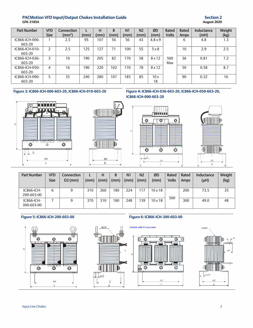
IC866-ICH-006-603-20
1 2.5 95 107 56 56 43 4.8 x 9
500 Max
6 4.8 1.3
IC866-ICH-010-603-20
2 2.5 125 127 71 100 55 5 x 8 10 2.9 2.5
IC866-ICH-036-603-20
3 10 190 205 82 170 58 8 x 12 36 0.81 7.2
IC866-ICH-050-603-20
4 16 190 220 102 170 78 8 x 12 50 0.58 8.7
IC866-ICH-090-603-20
5 35 240 280 107 185 85 10 x 18
90 0.32 16
Figure 3: IC866-ICH-006-603-20, IC866-ICH-010-603-20
Figure 4: IC866-ICH-036-603-20, IC866-ICH-050-603-20,
IC866-ICH-090-603-20
Part Number VFD
Size
Connection
D2 (mm)
L
(mm)
H
(mm)
B
(mm)
N1
(mm)
N2
(mm)
ØD
(mm)
Rated
Volts
Rated
Amps
Inductance
(μH)
Weight
(kg)
IC866-ICH-200-603-00
6 9 310 260 180 224 117 10 x 18
500
200 73.5 35
IC866-ICH-300-603-00
7 9 370 310 180 248 139 10 x 18 300 49.0 48
Figure 5: IC866-ICH-200-603-00
Figure 6: IC866-ICH-300-603-00

PACMotion VFD Input/Output Chokes Installation Guide Section 2 GFK-3185A August 2020
Input Line Chokes 4
2.3 Mounting Dimensions – IP66 Versions
Part Number VFD Size
Connection (mm2)
L (mm)
H (mm)
B (mm)
N1 (mm)
N2 (mm)
ØD (mm)
L1 (mm)
H1 (mm)
B1 (mm)
Rated Volts
Rated Amps
Inductance (mH)
Weight (kg)
IC866-ICH-016-201-60
1 4 82 70 70 70 58 6 151 60 85
230 Max
16 1.83 1.0
IC866-ICH-025-201-60
2 10 90 75 84 84 72 6 151 60 85 25 1.17 1.3
IC866-ICH-006-603-60
1 2.5 115 88 74 80 60 5.5 x 7 151 60 85
600 Max
6 4.8 1.6
IC866-ICH-010-603-60
2 2.5 175 137 99 130 79 5.5 x 12 151 60 85 10 3.86 3.5
IC866-ICH-018-603-60
3 10 175 137 114 130 94 5.5 x 12 151 60 85 18 2.04 7
Figure 7: Dimensions of Enclosed Versions
2.4 Installation Schematic Diagram
Figure 8: Single-Phase Supply Installation
Figure 9: Three-Phase Supply Installation
PACMotion VFD Input/Output Chokes Installation Guide Section 3 GFK-3185A August 2020
Output Line Chokes 5
Section 3: Output Line Chokes
3.1 Using Output Chokes
AC Inverters use a fast switching pulse width modulation (PWM) technique to create a variable
frequency AC Output to the connected motor. The fast switching of the output of the drive when
connected with long motor cables results in a reflected voltage at the motor which can be up to three
times the AC supply voltage, with a very fast rise time. Output chokes help to reduce this peak voltage,
and increase the rise time, to reduce the stress applied to the motor insulation and prevent damage.
Output chokes are recommended whenever any of the following conditions are met:
• The connected motor is not known to be suitable for use with a PWM output Inverter (as
confirmed with the motor manufacturer)
• The motor cable length exceeds the maximum permissible motor cable length stated for the
product in the relevant user manual
o Specified cable lengths apply to standard type copper shielded cable only
o For unshielded cables, the maximum length may increase by 50%
o Using a choke allows the maximum cable length to increase by 100%
• High capacitance motor cable is used, e.g. typically fire-resistant cables
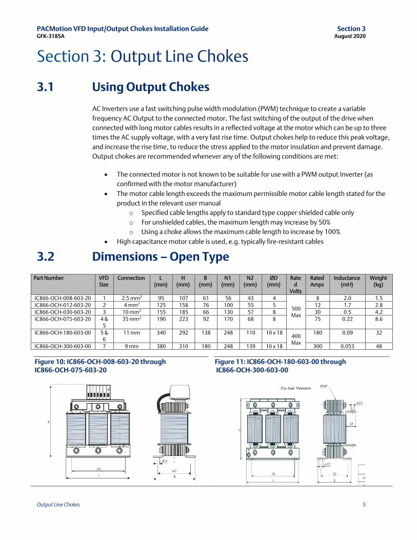
3.2 Dimensions – Open Type
Part Number VFD Size
Connection
L (mm)
H (mm)
B (mm)
N1 (mm)
N2 (mm)
ØD (mm)
Rated
Volts
Rated Amps
Inductance (mH)
Weight (kg)
IC866-OCH-008-603-20 1 2.5 mm2 95 107 61 56 43 4
500 Max
8 2.0 1.5
IC866-OCH-012-603-20 2 4 mm2 125 158 76 100 55 5 12 1.7 2.8
IC866-OCH-030-603-20 3 10 mm2 155 185 66 130 57 8 30 0.5 4.2
IC866-OCH-075-603-20 4 & 5
35 mm2 190 223 92 170 68 8 75 0.22 8.6
IC866-OCH-180-603-00 5 & 6
11 mm 340 292 138 248 110 10 x 18 400 Max
180 0.09 32
IC866-OCH-300-603-00 7 9 mm 380 310 180 248 139 10 x 18 300 0.053 48
Figure 10: IC866-OCH-008-603-20 through IC866-OCH-075-603-20
Figure 11: IC866-OCH-180-603-00 through IC866-OCH-300-603-00
PACMotion VFD Input/Output Chokes Installation Guide Section 3 GFK-3185A August 2020
Output Line Chokes 6
3.3 Mounting Dimensions – Enclosed Versions
Part Number VFD
Size
Connection
(mm2)
L
(mm)
H
(mm)
B
(mm)
N1
(mm)
N2
(mm)
ØD
(mm)
L1
(mm)
H1
(mm)
B1
(mm)
Rated
Volts
Rated
Amps
Inductance
(mH)
Weight
(kg)
IC866-OCH-008-603-60 1 2.5 115 85 74 80 60 5.5 x 7 151 60 85
600
Max
8 2.0 1.7
IC866-OCH-012-603-60 2 2.5 140 110 87 100 70 5.5 x 12 151 60 85 12 1.2 3.2
IC866-OCH-018-603-60 3 10 140 110 87 100 70 5.5 x 12 151 60 85 18 0.9 3.2
Figure 12:Mounting Dimensions – Enclosed Versions
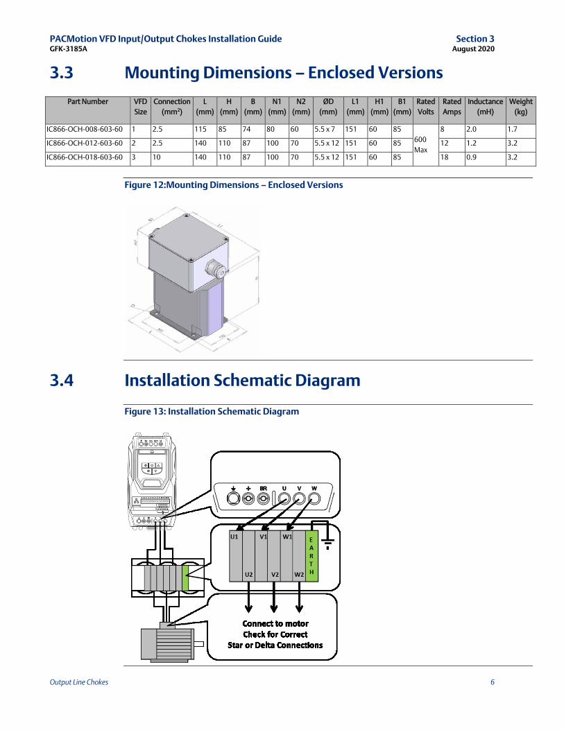
3.4 Installation Schematic Diagram
Figure 13: Installation Schematic Diagram

General Contact Information
Home link: http://www.emerson.com/industrial-automation-controls
Knowledge Base: https://www.emerson.com/industrial-automation-controls/support
Technical Support
Americas Phone: 1-888-565-4155 1-434-214-8532 (If toll free option is unavailable)
Customer Care (Quotes/Orders/Returns): [email protected] Technical Support: [email protected]
Europe Phone: +800-4444-8001 +420-225-379-328 (If toll free option is unavailable)
Customer Care (Quotes/Orders/Returns): [email protected] Technical Support: [email protected]
Asia Phone: +86-400-842-8599 +65-6955-9413 (All other Countries)
Customer Care (Quotes/Orders/Returns): [email protected] Technical Support: [email protected]
Any escalation request should be sent to: [email protected]
Note: If the product is purchased through an Authorized Channel Partner, please contact the seller directly for any support.
Emerson reserves the right to modify or improve the designs or specifications of the products mentioned in this manual at
any time without notice. Emerson does not assume responsibility for the selection, use or maintenance of any product.
Responsibility for proper selection, use, and maintenance of any Emerson product remains solely with the purchaser.
© 2020 Emerson. All rights reserved.
Emerson Terms and Conditions of Sale are available upon request. The Emerson logo is a trademark and service mark of Emerson Electric Co. All other marks are the property of their respective owners.


