© 2013 MITSUBISHI HEAVY INDUSTRIES, LTD. All Rights Reserved.
Overview of the Risk Assessment for Chiller
JRAIA Chiller Risk Assessment SWG Chief investigatorKenji Ueda (Mitsubishi Heavy Industries, Ltd.)Members
Mikio Ito, Tomokazu Tashimo, Isao Iba, Hiroichi YamaguchiMamoru Senda, Masayuki Aiyama, Shuji Fukano, Takuho HiraharaTetsuji Saikusa, Yoshihiro Sumida, Koji Yamashita,Yosuke Mukai, Naoki Kobayashi
Today’s Outlines
1© 2015 JRAIA The Japan Refrigeration and Air Conditioning Industry Association. All Rights Reserved.
Schedule
Regal system in JapanRisk assessment detailCountermeasureGL
Conclusions
1.Risk assessment process chart of chiller SWG
2
2011Fy 2012Fy 2013Fy 2014Fy 2015Fy
Kobe symposium◆ Final report◆
JRA-GL◆
▼P report※ ▼P report※ ▼P report※
Kobe symposium◆
© 2015 JRAIA The Japan Refrigeration and Air Conditioning Industry Association. All Rights Reserved.
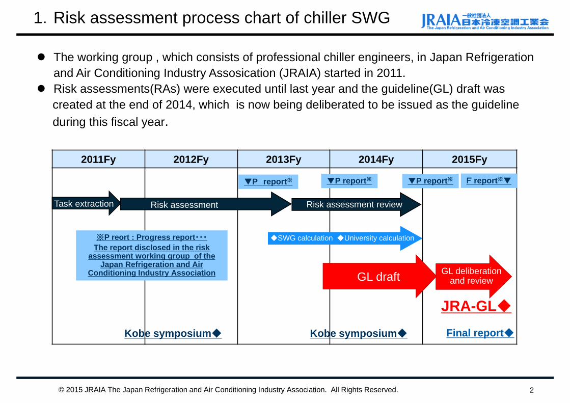
※P reort : Progress report・・・
The report disclosed in the risk assessment working group of the
Japan Refrigeration and Air Conditioning Industry Association
The working group , which consists of professional chiller engineers, in Japan Refrigeration and Air Conditioning Industry Assosication (JRAIA) started in 2011.
Risk assessments(RAs) were executed until last year and the guideline(GL) draft was created at the end of 2014, which is now being deliberated to be issued as the guideline during this fiscal year.
Task extraction Risk assessment Risk assessment review
GL draft GL deliberation and review
◆SWG calculation ◆University calculation
F report※▼
4.リスクアセスメントの構成概要(1)
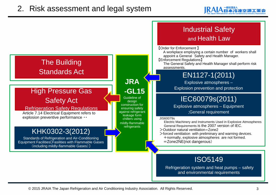
Industrial Safety and Health Law
Article 7.14 Electrical Equipment refers to explosion preventive performance ・・ JIS60079s
Electric Machinery and Instruments Used in Explosive Atmospheres General Requirements is the 2007 version of IEC.
>Outdoor natural ventilation=Zone2>forced ventilation with preliminary and warning devices.
+normally, explosive atmospheres are not formed. =Zone2NE(not dangerous)
The Building Standards Act
KHK0302-3(2012)Standards of Refrigeration and Air-Conditioning
Equipment Facilities〔Fasilities with Flammable Gases (including mildly-flammable Gases)〕
ISO5149Refrigeration system and heat pumps – safety
and environmental requirements
JRA-GL15Guideline of
design construction for ensuring safety
against refrigerant leakage form chillers using
mildly-flammable refrigerants
2. Risk assessment and legal system
3© 2015 JRAIA The Japan Refrigeration and Air Conditioning Industry Association. All Rights Reserved.
【Order for Enforcement 】A workplace employing a certain number of workers shall appoint a General Safety and Health Manager.
【Enforcement Regulations】The General Safety and Health Manager shall perform risk assessments.
EN1127-1(2011) Explosive atmospheres –
Explosion prevention and protection
IEC60079s(2011) Explosive atmospheres – Equipment
;General requirement
High Pressure Gas Safety Act
Refrigeration Safety Regulations
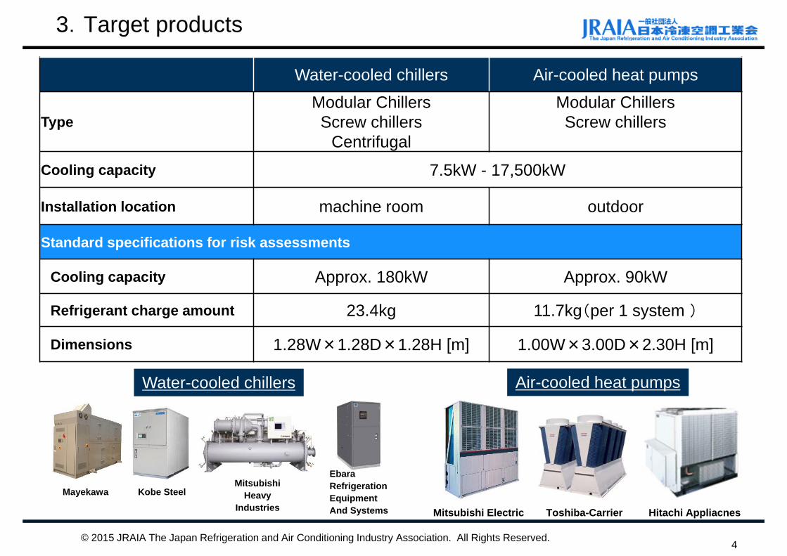
3.Target products
4© 2015 JRAIA The Japan Refrigeration and Air Conditioning Industry Association. All Rights Reserved.
Water-cooled chillers Air-cooled heat pumps
TypeModular ChillersScrew chillers
Centrifugal
Modular ChillersScrew chillers
Cooling capacity 7.5kW - 17,500kW
Installation location machine room outdoor
Standard specifications for risk assessments
Cooling capacity Approx. 180kW Approx. 90kW
Refrigerant charge amount 23.4kg 11.7kg(per 1 system )
Dimensions 1.28W×1.28D×1.28H [m] 1.00W×3.00D×2.30H [m]
Ebara Refrigeration Equipment And Systems
Mayekawa Kobe SteelMitsubishi
HeavyIndustries Mitsubishi Electric Toshiba-Carrier Hitachi Appliacnes
Water-cooled chillers Air-cooled heat pumps
4. Acceptable probability of harm
5
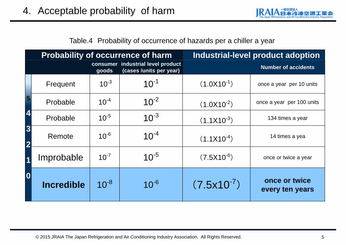
Table.4 Probability of occurrence of hazards per a chiller a year
Probability of occurrence of harm Industrial-level product adoptionconsumer
goodsindustrial level product(cases /units per year) Number of accidents
5
4
3
2
1
0
Frequent 10-3 10-1 (1.0X10⁻¹) once a year per 10 units
Probable 10-4 10-2(1.0X10⁻²) once a year per 100 units
Probable 10-5 10-3(1.1X10⁻³) 134 times a year
Remote 10-6 10-4(1.1X10⁻⁴) 14 times a yea
Improbable 10-7 10-5 (7.5X10⁻⁶) once or twice a year
Incredible 10-8 10-6 (7.5x10⁻⁷)once or twice
every ten years
© 2015 JRAIA The Japan Refrigeration and Air Conditioning Industry Association. All Rights Reserved.
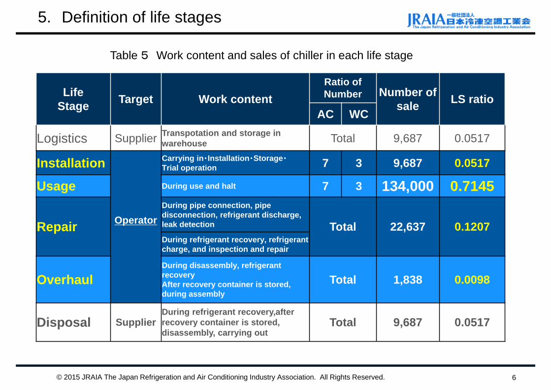
5. Definition of life stages
6
LifeStage Target Work content
Ratio of Number Number of
sale LS ratioAC WC
Logistics Supplier Transpotation and storage in warehouse Total 9,687 0.0517
Installation
Operator
Carrying in・Installation・Storage・Trial operation 7 3 9,687 0.0517
Usage During use and halt 7 3 134,000 0.7145
Repair
During pipe connection, pipedisconnection, refrigerant discharge,leak detection Total 22,637 0.1207During refrigerant recovery, refrigerant charge, and inspection and repair
OverhaulDuring disassembly, refrigerant recovery After recovery container is stored, during assembly
Total 1,838 0.0098
Disposal SupplierDuring refrigerant recovery,after recovery container is stored,disassembly, carrying out
Total 9,687 0.0517
Table 5 Work content and sales of chiller in each life stage
© 2015 JRAIA The Japan Refrigeration and Air Conditioning Industry Association. All Rights Reserved.
7
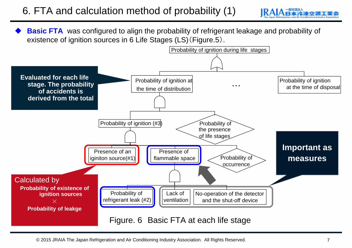
Basic FTA was configured to align the probability of refrigerant leakage and probability of existence of ignition sources in 6 Life Stages (LS)(Figure.5).
Figure. 6 Basic FTA at each life stage
Calculated by Probability of existence of
ignition sources×
Probability of leakge
Evaluated for each life stage. The probability
of accidents is derived from the total
Important as measures
© 2015 JRAIA The Japan Refrigeration and Air Conditioning Industry Association. All Rights Reserved.
Probability of ignition during life stages
Probability ofthe presence of life stages
Probability of ignition atthe time of distribution
Probability of ignitionat the time of disposal
Probability of ignition (#3)
Presence of an iginiton source(#1)
Probability of refrigerant leak (#2)
・・・
Presence of flammable space
Lack ofventilation
No-operation of the detectorand the shut-off device
Probability of occurrence
6. FTA and calculation method of probability (1)
8
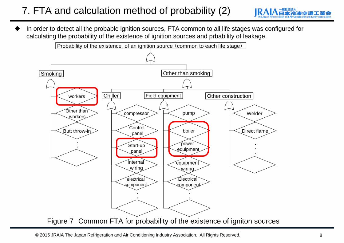
In order to detect all the probable ignition sources, FTA common to all life stages was configured for calculating the probability of the existence of ignition sources and prbability of leakage.
Figure 7 Common FTA for probability of the existence of igniton sources
© 2015 JRAIA The Japan Refrigeration and Air Conditioning Industry Association. All Rights Reserved.
Probability of the existence of an ignition source (common to each life stage)
Smoking
workers
Other thanworkers
Other than smoking
compressor
Control panelButt throw-in
Chiller
Start-uppanel
Internal wiring
electricalcomponent
pump
boiler
Field equipment
power equipment
equipmentwiring
Electrical component
・・・
・・・
・・・
Welder
Direct flame
Other construction
・・・
7. FTA and calculation method of probability (2)

8. Frequency of refrigerant leakage accidents
9
We estimated the record with the actual accident data RA members submitted①The total shipment volume of water-cooled (W/C) chillers, air-cooled (A/C) chillers, and turbo chillers are
derived from the annual shipment volume of chiller SWG companies. ②Annual proportional rates against the summarized data of this study were derived from annual shipment
volume provided by JRAIA. ③Total numbers of leakage cases were determined by adding each company’s number of WC, AC, and
turbo chiller leakage cases . ④Total number of leakage cases was estimated by the proportional rate of each chiller SWG company. ⑤Frequency of leakage was determined by deviding estimated total number by the volume of METI stock
units (130 K units). (The ratio of WC/AC chillers was assumed to be 3:7.)
© 2015 JRAIA The Japan Refrigeration and Air Conditioning Industry Association. All Rights Reserved.
2004-2011
Frequency of leakage (cases/units・year)
W/C chiller A/C HP Centrifugal Total
burst leak 5.83×10⁻⁶ 1.35×10⁻⁵ 0 1.07×10⁻⁵
rapid leak 1.07×10⁻⁴ 1.87×10⁻⁴ 0 1.56×10⁻⁴
slow leak 1.64×10⁻³ 2.21×10⁻³ 7.09×10⁻³ 2.27×10⁻³
Table 8 Frequency of leakage occurrence for each leakage rate from fiscal 2004 to 2011.
9. Machine room model (Image)
10
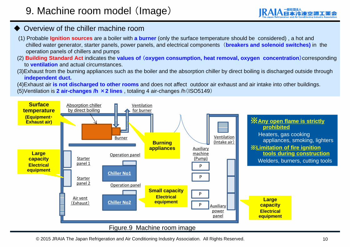
Overview of the chiller machine room (1) Probable Ignition sources are a boiler with a burner (only the surface temperature should be considered) , a hot and
chilled water generator, starter panels, power panels, and electrical components (breakers and solenoid switches) in the operation panels of chillers and pumps
(2) Building Standard Act indicates the values of (oxygen consumption, heat removal, oxygen concentration)correspondingto ventilation and actual circumstances.
(3)Exhaust from the burning appliances such as the boiler and the absorption chiller by direct boiling is discharged outside through independent duct.
(4)Exhaust air is not discharged to other rooms and does not affect outdoor air exhaust and air intake into other buildings. (5)Ventilation is 2 air-changes /h ×2 lines , totaling 4 air-changes /h(ISO5149)
Chiller No2
Chiller No1
P
P
P
P
Operation panel
Operation panel
Starter panel 1
Starter panel 2
Auxiliary machine(Pump)
Auxiliary power panel
Burner
Air vent(Exhaust)
Ventilation(Intake air)
Ventilationfor burner
Large capacityElectrical
equipment
Small capacityElectrical
equipment Large capacityElectrical
equipment
Surface temperature(Equipment・Exhaust air)
Burning appliances
Figure.9 Machine room image
※Any open flame is strictly prohibited
Heaters, gas cooking appliances, smoking, lighters
※Limitation of fire ignition tools during construction
Welders, burners, cutting tools
© 2015 JRAIA The Japan Refrigeration and Air Conditioning Industry Association. All Rights Reserved.
Absorption chiller by direct boiling
10. Ignition sources(igniton assessment)
11
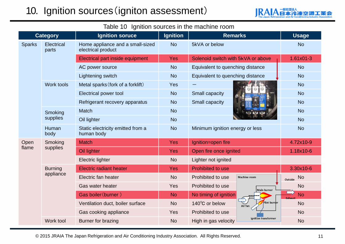
Table 10 Ignition sources in the machine roomCategory Ignition soruce Ignition Remarks Usage
Sparks Electricalparts
Home appliance and a small-sized electrical product
No 5kVA or below No
Electrical part inside equipment Yes Solenoid switch with 5kVA or above 1.61x01-3
AC power source No Equivalent to quenching distance No
Lightening switch No Equivalent to quenching distance No
Work tools Metal sparks(fork of a forklift) Yes - No
Electrical power tool No Small capacity No
Refrigerant recovery apparatus No Small capacity No
Smokingsupplies
Match No No
Oil lighter No No
Humanbody
Static electricity emitted from a human body
No Minimum ignition energy or less No
Openflame
Smokingsupplies
Match Yes Ignition=open fire 4.72x10⁻⁹
Oil lighter Yes Open fire once ignited 1.18x10⁻⁶
Electric lighter No Lighter not ignited
Burningappliance
Electric radiant heater Yes Prohibited to use 3.30x10⁻⁶
Electric fan heater No Prohibited to use No
Gas water heater Yes Prohibited to use No
Gas boiler(burner ) No No timing of ignition No
Ventilation duct, boiler surface No 140℃ or below No
Gas cooking appliance Yes Prohibited to use No
Work tool Burner for brazing No High in gas velocity No
© 2015 JRAIA The Japan Refrigeration and Air Conditioning Industry Association. All Rights Reserved.
11. Machine room model(installation layout)
12
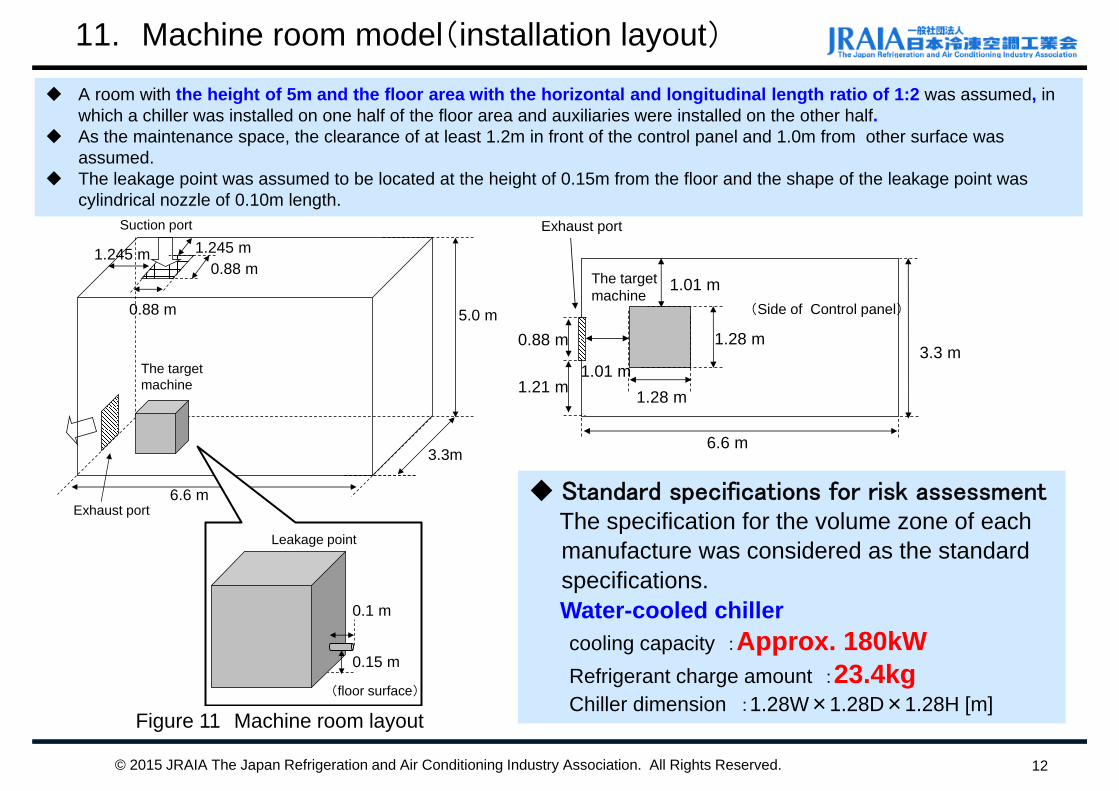
A room with the height of 5m and the floor area with the horizontal and longitudinal length ratio of 1:2 was assumed, in which a chiller was installed on one half of the floor area and auxiliaries were installed on the other half.
As the maintenance space, the clearance of at least 1.2m in front of the control panel and 1.0m from other surface was assumed.
The leakage point was assumed to be located at the height of 0.15m from the floor and the shape of the leakage point was cylindrical nozzle of 0.10m length.
6.6 m
5.0 m
The targetmachine
3.3m
Suction port
Exhaust port
1.245 m 1.245 m
0.88 m
0.88 m
(floor surface)
0.15 m
0.1 m
Leakage point
6.6 m
1.01 m
1.01 m
1.28 m
The target machine
1.28 m
3.3 m
(Side of Control panel)
Exhaust port
0.88 m
1.21 m
Figure 11 Machine room layout
© 2015 JRAIA The Japan Refrigeration and Air Conditioning Industry Association. All Rights Reserved.
Standard specifications for risk assessmentThe specification for the volume zone of each manufacture was considered as the standardspecifications. Water-cooled chillercooling capacity :Approx. 180kWRefrigerant charge amount :23.4kgChiller dimension :1.28W×1.28D×1.28H [m]
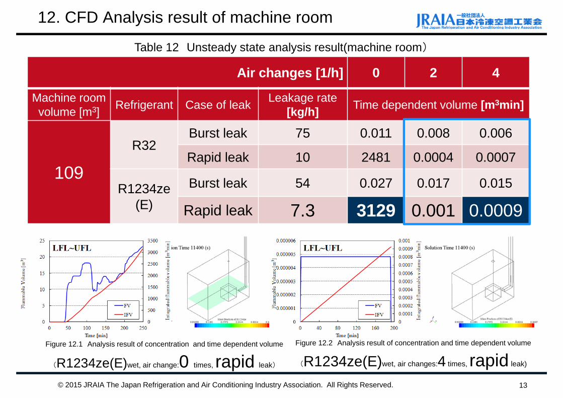
12. CFD Analysis result of machine room
13
Table 12 Unsteady state analysis result(machine room)
Figure 12.1 Analysis result of concentration and time dependent volume
(R1234ze(E)wet, air change:0 times, rapid leak)
Figure 12.2 Analysis result of concentration and time dependent volume
(R1234ze(E)wet, air changes:4 times, rapid leak)
Air changes [1/h] 0 2 4
Machine room volume [m3] Refrigerant Case of leak Leakage rate
[kg/h] Time dependent volume [m3min]
109R32
Burst leak 75 0.011 0.008 0.006
Rapid leak 10 2481 0.0004 0.0007
R1234ze(E)
Burst leak 54 0.027 0.017 0.015
Rapid leak 7.3 3129 0.001 0.0009
© 2015 JRAIA The Japan Refrigeration and Air Conditioning Industry Association. All Rights Reserved.
12.空冷HPモデルの特定
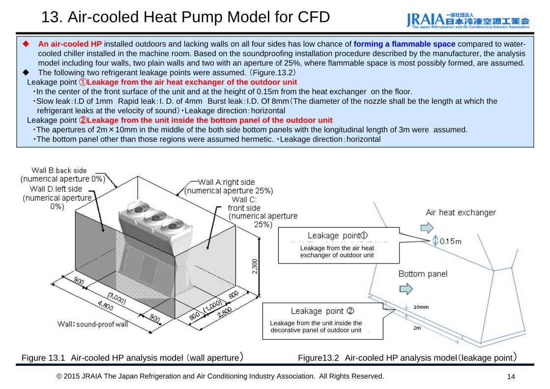
An air-cooled HP installed outdoors and lacking walls on all four sides has low chance of forming a flammable space compared to water-cooled chiller installed in the machine room. Based on the soundproofing installation procedure described by the manufacturer, the analysis model including four walls, two plain walls and two with an aperture of 25%, where flammable space is most possibly formed, are assumed.
The following two refrigerant leakage points were assumed. (Figure.13.2)Leakage point ①Leakage from the air heat exchanger of the outdoor unit
・In the center of the front surface of the unit and at the height of 0.15m from the heat exchanger on the floor. ・Slow leak:I.D of 1mm Rapid leak:I. D. of 4mm Burst leak:I.D. Of 8mm(The diameter of the nozzle shall be the length at which the
refrigerant leaks at the velocity of sound)・Leakage direction:horizontalLeakage point ②Leakage from the unit inside the bottom panel of the outdoor unit
・The apertures of 2m×10mm in the middle of the both side bottom panels with the longitudinal length of 3m were assumed. ・The bottom panel other than those regions were assumed hermetic. ・Leakage direction:horizontal
14
13. Air-cooled Heat Pump Model for CFD
Figure 13.1 Air-cooled HP analysis model (wall aperture) Figure13.2 Air-cooled HP analysis model(leakage point)
© 2015 JRAIA The Japan Refrigeration and Air Conditioning Industry Association. All Rights Reserved.
Leakage from the air heat exchanger of outdoor unit
Leakage from the unit inside the decorative panel of outdoor unit
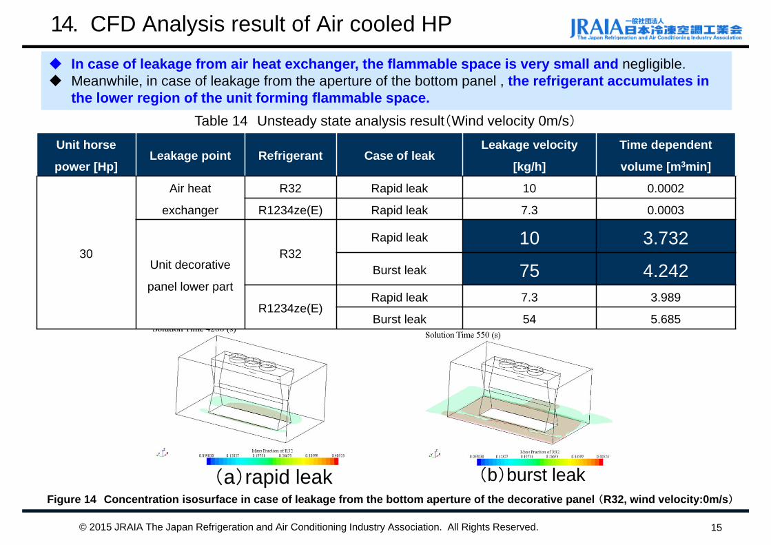
In case of leakage from air heat exchanger, the flammable space is very small and negligible. Meanwhile, in case of leakage from the aperture of the bottom panel , the refrigerant accumulates in
the lower region of the unit forming flammable space.
14. CFD Analysis result of Air cooled HP
15
Table 14 Unsteady state analysis result(Wind velocity 0m/s)
Figure 14 Concentration isosurface in case of leakage from the bottom aperture of the decorative panel (R32, wind velocity:0m/s)
(a)rapid leak (b)burst leak
© 2015 JRAIA The Japan Refrigeration and Air Conditioning Industry Association. All Rights Reserved.
Unit horse
power [Hp]Leakage point Refrigerant Case of leak
Leakage velocity
[kg/h]
Time dependent
volume [m3min]
30
Air heat
exchanger
R32 Rapid leak 10 0.0002
R1234ze(E) Rapid leak 7.3 0.0003
Unit decorative
panel lower part
R32Rapid leak 10 3.732Burst leak 75 4.242
R1234ze(E)Rapid leak 7.3 3.989
Burst leak 54 5.685
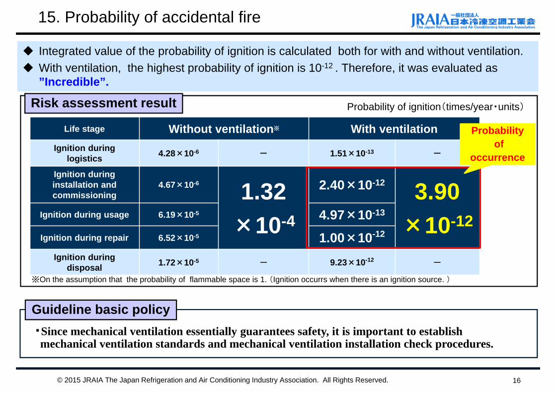
15. Probability of accidental fire
16
Integrated value of the probability of ignition is calculated both for with and without ventilation. With ventilation, the highest probability of ignition is 10-12 . Therefore, it was evaluated as
”Incredible”.
Risk assessment result
Life stage Without ventilation※ With ventilationIgnition during
logistics 4.28×10⁻⁶ - 1.51×10⁻¹³ -
Ignition during installation and commissioning
4.67×10⁻⁶ 1.32×10⁻⁴
2.40×10⁻¹² 3.90×10⁻¹²Ignition during usage 6.19×10⁻⁵ 4.97×10⁻¹³
Ignition during repair 6.52×10⁻⁵ 1.00×10⁻¹²
Ignition during disposal 1.72×10⁻⁵ - 9.23×10⁻¹² -
Guideline basic policy・Since mechanical ventilation essentially guarantees safety, it is important to establish mechanical ventilation standards and mechanical ventilation installation check procedures.
※On the assumption that the probability of flammable space is 1. (Ignition occurrs when there is an ignition source. )
Probability of ignition(times/year・units)
© 2015 JRAIA The Japan Refrigeration and Air Conditioning Industry Association. All Rights Reserved.
Probabilityof
occurrence
17© 2015 JRAIA The Japan Refrigeration and Air Conditioning Industry Association. All Rights Reserved.
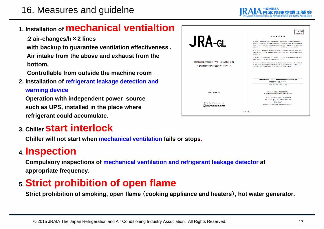
16. Measures and guidelne
1. Installation of mechanical ventialtion:2 air-changes/h×2 lineswith backup to guarantee ventilation effectiveness .Air intake from the above and exhaust from the bottom.Controllable from outside the machine room
2. Installation of refrigerant leakage detection and warning deviceOperation with independent power source such as UPS, installed in the place where refrigerant could accumulate.
3. Chiller start interlock Chiller will not start when mechanical ventilation fails or stops.
4. InspectionCompulsory inspections of mechanical ventilation and refrigerant leakage detector at appropriate frequency.
5. Strict prohibition of open flameStrict prohibition of smoking, open flame (cooking appliance and heaters), hot water generator.
17. Conclusion
18© 2015 JRAIA The Japan Refrigeration and Air Conditioning Industry Association. All Rights Reserved.
The results of Risk assessment for chillers,
・the probability of accidental fire and burn using the flammable refrigerant is 3.9 x 10⁻¹² with appropriate measures. It is smaller than once every hundred years.
・2-Independent mechanical ventilation lines will be required on the GL as most important countermeasure to preventaccident in the machine room
・We are going to develop JRA-GL and general overview of RAin 2015fy.

Thank you for your attention.
19© 2015 JRAIA The Japan Refrigeration and Air Conditioning Industry Association. All Rights Reserved.


