Download - Optimization of Multirotor UAV Endurance

FACULTY OF SCIENCE AND TECHNOLOGY
MASTER’S THESIS
Study programme/specialisation: Master of Science and Engineering
Structures and Materials/
Renewable Energy
Spring semester, 2020
Open
Author:
Sølve Sætre Sem
Programme coordinator:
Dimitrios Pavlou
Supervisors:
Dimitrios Pavlou, Jørgen Apeland (external)
Title of master’s thesis: Optimization of Multirotor UAV Endurance
Credits:
30
Keywords: Multirotor,
Unmanned Aerial Vehicle,
Rotary wing,
Endurance,
Analysis
Number of pages: 33 + supplemental material:
Appendix: 30 pages
Stavanger, 15th of June 2020
Title page for master’s thesis
Faculty of Science and Technology


Optimization of Multirotor UAVEndurance
SØLVE SÆTRE SEM
Supervisor: Dimitrios PavlouAssociate Supervisor: Jørgen Apeland
A thesis submitted in fulfilment ofthe requirements for the degree of
Master of Science in Engineering Structures and Materials
Mechanical and Structural Engineering and Materials ScienceFaculty of Science and Technology
University of StavangerNorway
15th of June 2020

Abstract
Advancements in the technology of electric motors, batteries and control modules have
facilitated a steep increase in the interest of small battery-powered multirotor aircraft. Un-
manned areal vehicles (UAV) of this type are mechanically simple, robust, have high man-
euverability and a compact size due to their propulsion system. A critical issue in the design
process is the UAV’s limited flight time, or endurance, due to inefficiencies and a relatively
low endurance to weight ratio. This thesis gives an overview of the factors that influence
endurance, defines analytical models for the estimation of endurance and analyses the impact
of propeller diameter, configuration and battery size for a 25 kg maximum take-off weight
UAV. The endurance is found to be sensitive to all three factors. A case analysis is performed
to compare a set of design options to the existing "Staaker BG-200" UAV produced by Nordic
Unmanned AS, and improvement recommendations are presented. The maximum estimated
endurance increase found is 61%, resulting in an endurance of 96 minutes and 36 seconds.
This design is estimated to have a 91% increase in UAV length and a 52% decrease in payload
capacity. A more practical design was recommended, with 23% increased endurance and
$1892 decreased propulsion system cost compared to the Staaker BG-200 UAV.
iv

Acknowledgements
I would like to thank Professor Dimitrios Pavlou in his role as supervisor for this thesis
and for facilitating the cooperation with Nordic Unmanned AS on this highly interesting topic.
I have always admired how well structured, precise and clear his teachings are. I thank Jørgen
Apeland for his endless enthusiasm and drive as external supervisor and for his invaluable
help in limiting and structuring my scope for this surprisingly comprehensive problem. I
thank Professor Knut Erik Giljarhus and Senior Engineer Jørgen Grønsund in their curiousity
and their constructive roles for the multi-thesis project cooperation. I also thank Bachelor
students Stian Runestad Hidle and Vetle Byremo Ingebretsen for our helpful conversations,
and Master student Adrian Oter Falch Günther for his analytical insight.
v

Contents
Abstract iv
Acknowledgements v
Contents vi
List of Figures viii
List of Tables ix
Chapter 1 Introduction 1
Chapter 2 Overview 32.1 Propulsion System . . . . . . . . . . . . . . . . . . . . . . . . . . . . . . . . . . . . . . . . . . . . . . . . . . . . . . . 3
2.2 Electronics . . . . . . . . . . . . . . . . . . . . . . . . . . . . . . . . . . . . . . . . . . . . . . . . . . . . . . . . . . . . . . 7
2.3 Airframe . . . . . . . . . . . . . . . . . . . . . . . . . . . . . . . . . . . . . . . . . . . . . . . . . . . . . . . . . . . . . . . . 7
Chapter 3 Analytical Models 103.1 Hover Power Model . . . . . . . . . . . . . . . . . . . . . . . . . . . . . . . . . . . . . . . . . . . . . . . . . . . . . . 10
3.2 Mass Model . . . . . . . . . . . . . . . . . . . . . . . . . . . . . . . . . . . . . . . . . . . . . . . . . . . . . . . . . . . . . 12
3.3 UAV size . . . . . . . . . . . . . . . . . . . . . . . . . . . . . . . . . . . . . . . . . . . . . . . . . . . . . . . . . . . . . . . 14
3.4 Battery Capacity Model . . . . . . . . . . . . . . . . . . . . . . . . . . . . . . . . . . . . . . . . . . . . . . . . . . 15
Chapter 4 Analysis 174.1 Parameters . . . . . . . . . . . . . . . . . . . . . . . . . . . . . . . . . . . . . . . . . . . . . . . . . . . . . . . . . . . . . . 18
4.2 Configuration Analysis . . . . . . . . . . . . . . . . . . . . . . . . . . . . . . . . . . . . . . . . . . . . . . . . . . . 19
4.3 Case Analysis . . . . . . . . . . . . . . . . . . . . . . . . . . . . . . . . . . . . . . . . . . . . . . . . . . . . . . . . . . . 24
Chapter 5 Discussion and Conclusion 285.1 Discussion . . . . . . . . . . . . . . . . . . . . . . . . . . . . . . . . . . . . . . . . . . . . . . . . . . . . . . . . . . . . . . 28
5.2 Conclusion . . . . . . . . . . . . . . . . . . . . . . . . . . . . . . . . . . . . . . . . . . . . . . . . . . . . . . . . . . . . . . 32
5.3 Future Work . . . . . . . . . . . . . . . . . . . . . . . . . . . . . . . . . . . . . . . . . . . . . . . . . . . . . . . . . . . . 33
Bibliography 34vi
CONTENTS vii
Appendix A Master Script 39
Appendix B Mass Function 59
Appendix C Power Consumption Function 64
Appendix D Size Function 66

List of Figures
1.1 Staaker BG-200 2
2.1 Airfoil Cross Section [8] 5
3.1 Multirotor Dimensions 14
4.1 Mass Sensitivity 19
4.2 Relative Mass 19
4.3 Effect of Propeller Size 19
4.4 Configurations 21
4.5 Configuration by Payload Capacity 22
4.6 Configuration by mass 23
4.7 Configuration by Size 23
4.8 Size Comparison 27
viii

List of Tables
4.1 Configuration Analysis Setup 20
4.2 Case Analysis - Original 32Ah Battery 25
4.3 Case Analysis - 44Ah Battery 25
4.4 Case Analysis - Balanced Design Setup 26
4.5 Case Analysis - Balanced Design Results 26
ix

CHAPTER 1
Introduction
Advancements in the technology of electric motors, batteries and control modules have facilit-
ated a steep increase in the interest of small battery-powered multirotor aircraft capable of
hovering and vertical take-off and landing. The interest spans both recreation and commercial
applications such as aerial photography, maintenance inspection, 3D reconstruction, search
and rescue and disaster prevention [1]. Unmanned areal vehicles (UAV) of this type are
mechanically simple, robust, have high maneuverability and a compact size due to their
propulsion system. However, the associated drawbacks include efficiency losses compared to
singe-rotor aircraft, and a low ratio between flight time and weight typical of battery powered
electrical systems. This makes the flight time, henceforth addressed as endurance, a critical
issue in the design process.
Nordic Unmanned AS is a company that uses unmanned areal systems to deliver services
and solutions. The company was the driver behind the present thesis as well as two parallel
theses. In one of these theses two Bachelor students conducted an experimental study on
the performance of varying propeller sizes and the efficiency loss associated with coaxial
rotors. Coaxial rotors have pairs of two rotors aligned on one axis, like in Figure 1.1. The
other thesis studied the same by using numerical simulation. The present thesis will study
endurance more generally, although rotor configuration is set as a primary interest. The basis
for these three theses is the company’s existing UAV called Staaker BG-200, which is a rotary
wing coaxial 8-rotor aircraft with a maximum take-off weight (MTOW) of 25 kilograms.
1

2 1 INTRODUCTION
FIGURE 1.1: Staaker BG-200
The main problem of this thesis is defined as: How can the endurance of multirotor UAVs be
optimized? To pursue the answer to this question three scientific goals have been identified:
• Determine the factors that influence endurance
• Quantify the critical factors
• Suggest improvements to the Staaker BG-200 UAV and estimate the associated
endurance improvement
First, an overview of the relevant factors will be given in chapter 2. Next, chapter 3 will focus
on a selection of these factors and present analytical models. these models will then be used
in chapter 4 for quantitative analysis. Based on these results, a selection of designs will be
compared to the Staaker BG-200 in a case analysis. Finally, a recommendation to Nordic
Unmanned will be presented along with suggestions for future work.

CHAPTER 2
Overview
In literature, such as References [2]–[5], endurance t is typically estimated as the ratio of the
energy capacity E and the power consumed P .
t =E
P(2.1)
There is a large number of factors that affect the energy capacity and the power consumption
of multirotor UAVs. This thesis will attempt to organize the factors using the following three
categories, and each category will be addressed in the present chapter:
(1) Propulsion system
(2) Electronics
(3) Airframe
2.1 Propulsion System
The components included in the propulsion system of a battery powered multirotor UAV is here
defined as the propellers, motors, electronic speed controllers (ESC) and the battery/batteries,
similar to the definition used in Reference [6]. These components are directly involved in
the process of converting stored energy into aerodynamic lift. Together they account for
a minimum of 46% of the weight of the Staaker BG-200 reference UAV. Understandably,
optimization of the electrical propulsion system is critical to the vehicle’s endurance.3

4 2 OVERVIEW
The electronic speed controller will not be studied in detail in this thesis, but a brief explanation
follows. The ESC is connected between the power supply and the motor. It controls the motor
speed by manipulating the current or the voltage going to the motor based on signals from the
control module. For brushless motors the ESC must convert the DC output of the battery to
three-phase AC. Off-the-shelf ESCs can be purchased as a singe central unit to control all
motors, or separate units intended to control one motor each. The ESC has to accommodate
the necessary current strength and should be designed to minimize weight and maximise
conversion efficiency.
2.1.1 Battery
Perhaps the most obvious component to consider for endurance is the battery. Increasing the
battery size increases the energy capacity but also the mass of the propulsion system. This has
diminishing returns for a given rotor setup due to the increased power consumption needed to
lift the UAV. Therefore, the chosen battery should have a high specific energy. Specific energy
is the amount of energy stored per mass, and may be measured in watt-hours per kilogram.
Importantly, the battery must also be able to deliver a sufficient current to meet the power
demand. Lastly the battery must be rechargeable. As an example, lithium-ion batteries have
a high specific energy but a relatively low maximum current delivery [7]. Lithium-polymer
(Li-Po) batteries on the other hand have seen wide adoption by small UAVs because they have
both high specific energy and high maximum current delivery.
2.1.2 Propeller
For fixed wing applications, as well as for multirotor UAVs intended for high speed operations,
the propellers are designed to have peak performance when flying at higher speeds. The
propeller of a multirotor with hover and low speed applications should be specifically designed
for hover efficiency. There is an inherit trade off between hover efficiency and cruising
efficiency in the design of a propeller. This is in part due to the fact that the angle of attack
of the propeller blade changes as the incoming air speed relative to the UAV changes. A
2.1 PROPULSION SYSTEM 5
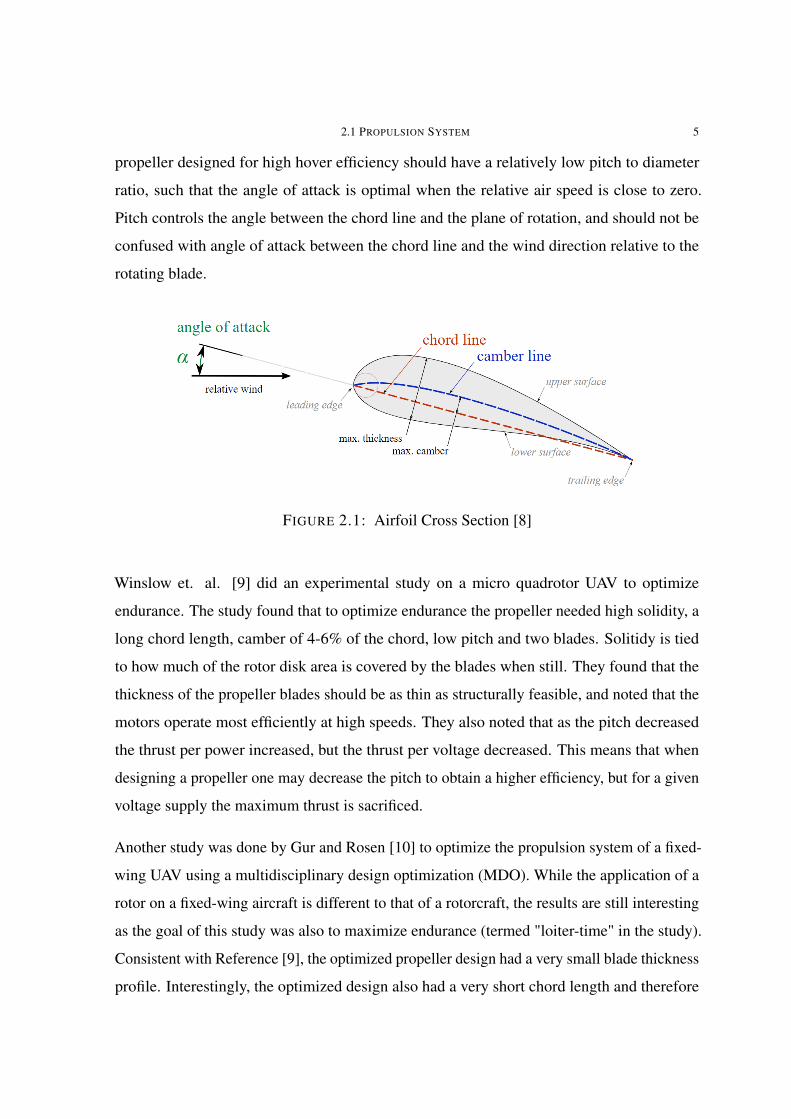
propeller designed for high hover efficiency should have a relatively low pitch to diameter
ratio, such that the angle of attack is optimal when the relative air speed is close to zero.
Pitch controls the angle between the chord line and the plane of rotation, and should not be
confused with angle of attack between the chord line and the wind direction relative to the
rotating blade.
FIGURE 2.1: Airfoil Cross Section [8]
Winslow et. al. [9] did an experimental study on a micro quadrotor UAV to optimize
endurance. The study found that to optimize endurance the propeller needed high solidity, a
long chord length, camber of 4-6% of the chord, low pitch and two blades. Solitidy is tied
to how much of the rotor disk area is covered by the blades when still. They found that the
thickness of the propeller blades should be as thin as structurally feasible, and noted that the
motors operate most efficiently at high speeds. They also noted that as the pitch decreased
the thrust per power increased, but the thrust per voltage decreased. This means that when
designing a propeller one may decrease the pitch to obtain a higher efficiency, but for a given
voltage supply the maximum thrust is sacrificed.
Another study was done by Gur and Rosen [10] to optimize the propulsion system of a fixed-
wing UAV using a multidisciplinary design optimization (MDO). While the application of a
rotor on a fixed-wing aircraft is different to that of a rotorcraft, the results are still interesting
as the goal of this study was also to maximize endurance (termed "loiter-time" in the study).
Consistent with Reference [9], the optimized propeller design had a very small blade thickness
profile. Interestingly, the optimized design also had a very short chord length and therefore

6 2 OVERVIEW
a very small solidity, contrary to Reference [9]. The authors first considered the optimal
thickness and chord to be structurally impractical, so they introduced structural constraints.
Even with these constraints, the resulting thickness and chord were still considered impractical
in terms of manufacturing.
2.1.3 Motor
The electric motors used for high endurance multirotor UAVs need to have high efficiency at
typical operating conditions. The theory behind making the motor perform more efficiently
is out of the scope of this thesis. In addition it is crucial that the motor is designed to be
lightweight. Gur and Rosen [10] looked at 250 existing brushless motors from various web
catalogues and tried to estimate a constant for the maximum rated power per mass, or power-
to-weight ratio, of the motors. The variance was so large that the estimated value for the
constant ranged from 110 to 800 W/kg, where individual motors were even more spread. For
reference, the U8II KV100 sold by T-MOTOR and used by the UAV Staaker BG-200 has
a maximum power-to-weight ratio of 5171 W/kg based on listed specifications [11]. Note
that the maximum power for the motor is only rated for 180 second intervals. At some point
reliability may be a concern when aiming to minimize motor weight, and other characteristics
like the aforementioned efficiency must be taken into account by the designer. Still, the motor
mass is an important factor for the endurance of a multirotor UAV.
Motor manufacturers often give a "KV" rating for each motor, called the speed constant.
This characteristic is defined as the no-load RPM generated per volt supplied to the motor,
and should not be confused with kilovolts. A motor with a higher KV rating can produce
higher speeds, but will typically generate less torque. Similarly to the power-to-weight ratio
estimate, Gur and Rosen [10] estimated the motor KV as a function of mass. The constant
estimates ranged from 50 to 600 RPM kg/V. For reference, the UII8 KV100 motor has a value
of 27.2 RPM kg/V. KV is notably modeled inversely proportional to mass. Because of the
large spread, a sensitivity study was done for the design optimization. They found a high
sensitivity for the power-to-weight ratio, but a negligible influence of the motor speed constant

2.3 AIRFRAME 7
parameter on the optimal motor selection. For the latter the model predicted a variation of 4%
in endurance, where the solution had a criteria of a minimum rate-of-climb of 2m/s.
2.1.4 Configuration
The configuration of a multirotor aircraft is the layout of the rotor components. The reference
Staaker BG-200 UAV has a coaxial configuration with eight rotors. This means it has four
pairs of rotors and four supporting arms (see Figure 1.1). Coaxial rotors have a significant
efficiency loss due to aerodynamic interference, but can provide increased thrust or a smaller
UAV size. Other common configurations are in-plane (non-coaxial) quad-, hexa- or octorotor.
A coaxial UAV with three arms is possible and still has complete movement control over
pitch/roll/yaw, but a more novel in-plane three-rotor design requires an additional mechanism
to control yaw such as tilting one rotor. The configuration is closely tied to practical factors
like the UAV size, availability of components and cost.
2.2 Electronics
The electronics category includes wiring and support components that are not considered part
of the propulsion system. These components impact endurance through wiring losses and
secondary power consumption. In addition, the control algorithm may significantly impact
the dynamic power consumption associated with stabilizing and maneuvering the UAV. The
present thesis assumes the effect of the electronics to be negligible in comparison to the
large power consumption of the motors, but future studies should analyse the impact of these
factors.
2.3 Airframe
The airframe category considers the weight, aerodynamics and solid dynamics of the UAV’s
airframe. High performance materials should be considered as mass is critical to any aircraft,
and the benefits might outweigh the additional cost. Very small low-cost multirotor UAVs

8 2 OVERVIEW
often use plastic as an inexpensive structural material with sufficient strength, toughness and
stiffness coupled with low mass density. UAVs designed for higher performance and UAVs
designed to carry small payloads often utilize more costly materials such as carbon fiber and
aluminum. Carbon fiber is very light, provides excellent stiffness and good strength, but
limited toughness which means it is prone to break under excessive load. It is also impractical
to repair. Aluminum is a light metal, is repairable and provides very good toughness due to its
ductility. It also exhibits good machinability and can benefit from economies of scale due to
larger production volumes compared to more niche materials like carbon fiber. An economic
alternative may be sandwiched materials that use thin layers of high performance materials
like carbon fiber with a lightweight core material like foam or balsa wood.
Winslow et. al. [9] constructed an airframe for a micro-quadrotor out of sandwiched boards
of carbon fiber and balsa wood. The airframe consisted of only 7.4% of the total weight. For
comparison, similarly sized quadrotors available on the marked had airframes consisting of
roughly 30-40% of the total mass, which leads to increases power consumption and decreased
endurance. Robustness may be compromised when minimizing the mass of an airframe in
terms of life span or damage resistance.
In terms of solid dynamics, stiffness and mass affects the resonance frequencies of the UAV.
Care should be taken to avoid a large dynamic response to the excitation forces caused by the
rotors. This response can in the best case lead to power losses. In the worst case it can lead to
failure of the control algorithm if the harmonic excitation of the sensory components lead to a
form of aliasing. The algorithm can misinterpret the signal from the vibrating sensors and
attempt to stabilize the UAV based on this, leading to unstable behaviour and loss of control.
The oscillation modes of the airframe of the reference UAV Staaker BG-200 was analyzed in
a previous thesis written by Fischer [12]. Multiple modes were found to be within the range
of the excitation frequencies of the rotors. The dynamic response was not included in the
scope.
Another factor which impacts endurance is aerodynamics. Excluding the propeller aerody-
namics, the UAV will experience drag due to the motion of air around it. For high-speed
operations the designer may take extra care to manage the total drag on the airframe and the

2.3 AIRFRAME 9
supporting components typically placed close to the center of the UAV. Regardless of the
operating conditions, drag on the airframe arm should be taken into account when trying to
maximize endurance. The arms are located directly in the high-speed airflow induced by the
propellers, and will as such be particularly prone to drag. This drag causes a loss in the rotor
thrust and therefore a reduced propulsion efficiency.
A study done by Theys et. al. [13] analyzed the relative efficiency impact from the aero-
dynamics of three arm designs. The first arm was a smooth 25 mm cylindrical tube. The
second arm was produced by 3D-printing an aerodynamically shaped arm and nacelle. The
study did not specify the dimensions of this arm, but from the figures the arm seems to have
roughly the same frontal area facing the airflow as the first arm. The study also did not clarify
if the 3D-printed arm had undergone any surface treatment. 3D-printed objects will typically
have an uneven surface which may cause additional drag. The third arm was a smooth 10
mm square tube. The relative change in propulsion efficiency compared to the 25 mm tube
was measured. For the 3D-printed arm an increase of 2-4% was measured at disk loading
between 50-100 N/m2. Disk loading (DL) is defined as the ratio between thrust force and the
rotor disk area, and may be measured as N/m2. For the 10 mm square tube an increase of
4-8% was measured in the same DL interval. For reference, the DL of the Staaker BG-200
UAV at maximum take-off weight is 77 N/m2. The study, while limited in scope and perhaps
robustness, suggests that significant gains in efficiency and by extension endurance can be
achieved by engineering an airframe arm with optimized coefficient of drag and frontal area.

CHAPTER 3
Analytical Models
The analysis in chapter 4 will be limited to a few key factors. The influence of take-off
weight on endurance is expected to be significant, and mass will therefore be analyzed. Rotor
configuration will also be studied as the effect of changing the configuration is unclear, and
is set as a primary interest by Nordic Unmanned. Parallel to the Bachelor thesis performing
an experimental study and the Master thesis performing simulation of the Staaker BG-200
propellers, the propeller diameter will also be analysed in the present thesis. As a UAV with
maximized endurance may involve impractical design features, this thesis will estimate the
resulting size of the UAV.
3.1 Hover Power Model
Endurance will be estimated using equation 2.1. For this an estimate of the power consumed
is needed, which will be adapted from Reference [14]. The UAV will be assumed to hover in
position for the duration of the flight. Abdilla et. al. [14] compared the power consumption of
a UAV in hover to the same UAV performing small harmonic motions in a vertical case and
a horizontal case, and found very similar power consumption. This suggests that for UAV
operations with slow movements, a hover assumption can be a good estimate for analysis.
Momentum theory gives steady state rotor hover power PR [W] for a single rotor [15]:
PR =T
32
ηRrP√2ρaπ
(3.1)
10

3.1 HOVER POWER MODEL 11
where, using SI units, T is the required thrust force, rP is the propeller radius, ρa is the density
of air and ηR is the rotor Figure of Merit (FM). FM was developed to study rotorcraft hover
power efficiency during the first half of the 20th century. It is defined as the ratio between
ideal hover power and actual hover power for a single rotor [16].
FM =TviPr
(3.2)
where T is thrust, vi is the induced air speed through the rotor disk and Pr is the actual power
consumed by the rotor. This merit is useful for relative comparisons of performance between
rotors, but not for absolute comparisons as was clarified by Leishman and Syal [17]. FM,
although non-dimensional, is influenced by a number of factors that makes it biased when
comparing rotors of different disk loading. Leishman and Syal [17] in their study presented
alternative definitions of FM that can be used for coaxial rotors to account for inherit losses
in the ideal power required, with the goal of judging the efficiency of a coaxial rotor more
realistically. To measure the aerodynamic efficiency of comparable rotors is however out of
the scope of this thesis, and therefore a single-rotor propulsion system efficiency factor ηPS
will be used together with a rotor interaction efficiency factor ηRI . ηPS is the ratio between
ideal hover power for an isolated rotor and the power consumed by the propulsion system
for one rotor. This accounts for the propeller efficiency, the motor efficiency and the ESC
efficiency. ηRI is the ratio between the sum of the power consumed by isolated rotors and the
total power consumed by the rotors when positioned in the intended configuration. In other
words, ηRI accounts for the efficiency loss of the non-isolated rotors due to aerodynamic
interaction.
If the thrust of a multirotor is assumed equally distributed between the rotors, and the total
thrust is substituted by T = mg for the hover condition, the multirotor hover power can be
derived as Equation 3.3 [14]:
PNR=
m32 g
32
ηPSηRIrP√2NRρaπ
(3.3)

12 3 ANALYTICAL MODELS
Power consumption increases exponentially with mass, is inversely proportional to the radius
of the propeller and decreases with increasing number of rotors. These factors are not
independent however. Increasing the radius of the propeller increases its mass. A bigger
propeller also occupies more space and will require longer and heavier arms. Increasing
the number of rotors directly adds mass and requires more space with the aforementioned
drawbacks. The optimal design cannot be determined by studying factors in isolation, and
therefore this thesis will include a dynamic mass model when estimating endurance.
3.2 Mass Model
The mass of the UAV is modeled as he sum of a constant mass mC and a variable mass mV .
Only the latter varies with the number of rotors, the size of the propellers and motors and
the number of rotors per arm. It is assumed that the hub structure will be able to support the
change in rotor mass and arm length.
m = mC +mV (3.4)
The constant mass includes the mass of items such as the battery, the hub structure, the control
units, the batteries and the payload. The variable mass includes the mass of the propellers,
the motors, the ESCs, the arms and their structural connection components. The mass of
the wiring is neglected. If the mass of each arm is marm, and the sum of the mass of the
remaining variable components per rotor is mvar then the total variable mass is:
mV =
{NR(mvar +marm), in-plane
NR(mvar +12marm), coaxial
(3.5)
where a factor of 12
is used in the coaxial case since the number of arms is half the number of
rotors. The mass of each arm is modeled as:

3.2 MASS MODEL 13
marm = mmplLarm (3.6)
where mmpl is the mass per length of the arm material and Larm is the length of the arm.
Larger battery powered multirotor UAVs such as the Staaker BG200 often use carbon fiber
tubes for arms, in which case mmpl is a constant. Larm can be estimated as a function of
the number of arms and the rotor size based on their geometric relationship by assuming a
constant angle between adjacent rotors and equal length arms.
The distance between two horizontally adjacent rotors will in practice be larger than two times
the propeller radius rP to avoid collision between the propellers and to mitigate aerodynamic
losses due to blade tip vertices. An effective radius kP rP can be used to better reflect the
distance between rotors, where the constant kP is larger than one. A value of 1.05 was used in
the analysis based on Reference [18]. The horizontal distance R from the center of the UAV
to the rotor as a function of propeller size and configuration (see Figure 3.1) is defined as [19]:
R =kP rPsin π
NA
(3.7)
where NA is the number of arms. The ideal arm length then becomes R−L0,hub where L0,hub
is the horizontal distance from the center of the hub to the root of the arm. L0,hub is assumed
to be 0.171 m for the reference UAV Staaker BG-200. The propellers must not collide with
other components connected to the hub such as a battery or a leg. For the propellers of the
Staaker BG-200 to avoid colliding with the legs, a minimum distance L0,arm from the root of
the arm to the propeller blade tip is assumed to be 0.158 m. With this consideration the arm
length must be at least rP + L0,arm. Equation 3.8 uses the maximum of the two arm length
models to ensure both the distance between propellers and the distance to protruding hub
components is considered.
Larm = max
{R− L0,hub
rP + L0,arm
(3.8)

14 3 ANALYTICAL MODELS
FIGURE 3.1: Multirotor Dimensions
3.3 UAV size
Similarly to Equation 3.8, the length of the UAV (along the roll axis) can be geometrically
estimated. The length will be compared to the endurance of configuration options in Chapter
4 as a secondary design consideration. This length will be used instead of the diagonal length
as it better represents the space occupied by the UAV for various configurations, especially in
relation to storage containers. As with the arm length, the UAV length must consider both
the distance between propellers and the distance from the propeller tip to protruding hub
components. Respectfully, Equations 3.9 and 3.10 are used for these two considerations.
L1 =2kP rPtan π
NA
(3.9)
L2 = 2(rP + L0)cos(π
NA
) (3.10)
where L0 is the minimum distance from the center of the UAV to the propeller blade tip
necessary to avoid colliding with hub components. L0 is then equal to the sum of L0,hub and
L0,arm. Finally the UAV length estimate is:

3.4 BATTERY CAPACITY MODEL 15
L = max
{L1
L2
(3.11)
This equation assumes an even number of at least four rotors and will underestimate the length
of configurations with three arms. A modification to Equation 3.11 will be used for the three
arms case which takes into account the fact that one arm is in line with the length of the UAV:
L3 =L
2+R (3.12)
3.4 Battery Capacity Model
Abdilla et. al. [14] tested different battery models to determine a good estimate for the
effective battery endurance for use in multirotor UAVs. They used a series of commercial
off-the-shelf three-cell (3S) Li-Po batteries in the experiments, and compared four models:
1) Ideal battery capacity t = Cnom
I
2) 0.8 capacity offset t = 0.8Cnom
I
3) 0.9 capacity offset t = 0.9Cnom
I
4) Peukert equation t = C1.01nomR
1−1.01nom
I1.01
where Cnom is the nominal battery capacity, I is the circuit current, and 1.01 is the Peukert
exponent which was the average value over the experiments conducted. The study highlighted
that the Peukert equation is not suitable for Li-Po batteries as it is only valid for constant
discharge rate and temperature in a limited working range. An offset of 0.9 was found to be
the best fit. Based on the results in Reference [14], the following equation will be used for the
energy capacity E:
E = kBCnomVnom (3.13)
16 3 ANALYTICAL MODELS
where kB is the battery capacity offset factor and Cnom and Vnom is the rated battery charge
and volt respectively. Although a kB value of 0.9 can be a good estimate, it can also be
determined experimentally and is dependent on battery State of Health (SoH) and discharge
rate. By substituting Equation 3.13 into the endurance equation (2.1) it is assumed that the
UAV flies until the battery can no longer provide enough power to hover. It is advisable for
normal operations to limit the depth of discharge (DOD) to less than 100%, for instance 80%.
This will significantly improve the life-span of the battery.

CHAPTER 4
Analysis
Endurance was used as the primary characteristic for analysis in line with the scientific goals
of this thesis. The specifications of the existing Staaker BG-200 UAV was used as the basis for
the analysis. The energy capacity was estimated using Equation 3.13 with the reference case
of 32 Ah nominal capacity and 44.4V nominal voltage. A MATLAB script was developed to
execute the analysis, which can be found in Appendix A.
It was desired to use the experimental data gathered from the parallel Bachelor thesis to
calculate the single-rotor propulsion system efficiency ηPS for the propellers and the rotor
interaction efficiency factor ηRI for the coaxial setup and use these in the analysis of this
thesis. The goal was to use values averaged between 28 inch propellers and 32 inch propellers,
and assume these values to be constant for all propeller and motor combinations. However,
the ηPS calculated from the experiments underestimated the endurance by 27% compared
to the reported maximum endurance of the existing reference UAV. The reason for the low
experimental ηPS is unclear.
For the two 28 inch propellers at hover thrust ηRI was calculated to be 0.763. This value
corresponds well with empirical data from previous experimental study [20]. The same
factor was for two 32 inch propellers calculated to be 0.521. One reason for this decrease in
efficiency is the spacing between the rotors which is fixed. With a fixed distance z between
propellers the increased propeller diameter dP leads to a decreased ratio zdP
. A small zdP
(<0.15) ratio is tied to a decrease in efficiency as demonstrated in studies such as [20]. The ηRI
factor was still not expected to decrease as much as it did. The Bachelor students discovered
that a propeller was mounted incorrectly for many of the measurements, including the coaxial
17
18 4 ANALYSIS
32 inch test. The discovery was unfortunately made too late to rectify the mistake with new
tests.
The reasonable ηRI calculated from the 28 inch propeller data was be used for further analysis
instead of the averaged value initially desired. Note that the efficiency losses due to interaction
between horizontally adjacent rotors is excluded as only one pair of rotors were used in the
test. The effect horizontal interaction has been measured to be small when the propellers do
not overlap in studies such as [20] and [13]. It may be noted that to the authors knowledge
this effect has not been tested for adjacent pairs of coaxial rotors. The interaction may be
more significant than what is observed with only two adjacent rotors. In place of the ηPS
based directly on the experiments, a value of 0.793 was estimated by solving Equation 3.3 for
ηPS using the reported maximum endurance of 60 minutes. It was assumed that zdP
is held
constant, which means that the distance between the coaxial propellers must be increased as
the propeller diameter increases.
4.1 Parameters
To demonstrate the effect of changing the mass of the UAV, Equations 3.3 and 2.1 were used
with the specifications of the Staaker BG-200 UAV (26 inch coax 8-rotor). Figure 4.1 shows
how endurance varies with take-off weight while holding all else constant. The endurance
is estimated to be 33 minutes and 44 seconds at the MTOW of 25 kg assuming constant
propulsion efficiency. This is 44% less than the reference endurance of 60 minutes. Figure
4.2 demonstrates the estimated relative change in endurance caused by a change in mass.
Decreasing the mass of the reference UAV by one kilogram gives an estimated endurance
increase of 5 minutes and 42 seconds.
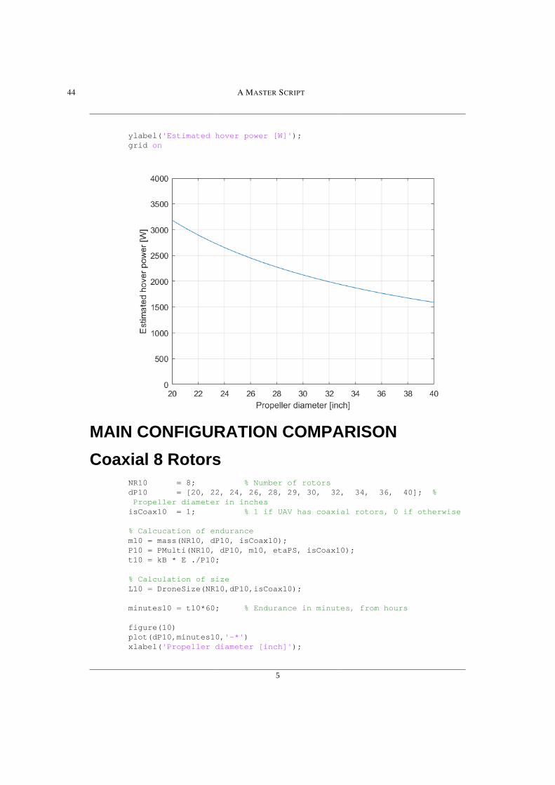
A demonstration of how hover power depends on propeller size can be seen in Figure 4.3.
The propeller diameter was varied from 20 to 40 inches holding all else constant. The mass
was fixed at the MTOW of 25 kg, and Staaker BG-200 specifications were used otherwise.
As the diameter doubled, the power consumption was halved for the same thrust.

4.2 CONFIGURATION ANALYSIS 19
FIGURE 4.1: Mass Sensitivity FIGURE 4.2: Relative Mass
FIGURE 4.3: Effect of Propeller Size
4.2 Configuration Analysis
To compare rotor configurations, the dynamic mass model was used including Equations 3.4,
3.5, 3.6 and 3.8 with zero payload. The propeller-, motor- and ESC mass data was taken from
the website of T-MOTOR [11], whom designs and sells UAV propulsion system components.
The carbon fiber "glossy" propellers were used for analysis, which is the propellers used for
the existing Staaker BG-200 UAV. This UAV has a thrust-to-weight ratio of 2.3 at MTOW
20 4 ANALYSIS
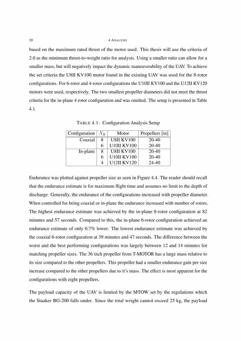
based on the maximum rated thrust of the motor used. This thesis will use the criteria of
2.0 as the minimum thrust-to-weight ratio for analysis. Using a smaller ratio can allow for a
smaller mass, but will negatively impact the dynamic maneuverability of the UAV. To achieve
the set criteria the U8II KV100 motor found in the existing UAV was used for the 8-rotor
configurations. For 6-rotor and 4-rotor configurations the U10II KV100 and the U12II KV120
motors were used, respectively. The two smallest propeller diameters did not meet the thrust
criteria for the in-plane 4 rotor configuration and was omitted. The setup is presented in Table
4.1.
TABLE 4.1: Configuration Analysis Setup
Configuration NR Motor Propellers [in]Coaxial 8 U8II KV100 20-40
6 U10II KV100 20-40In-plane 8 U8II KV100 20-40
6 U10II KV100 20-404 U12II KV120 24-40
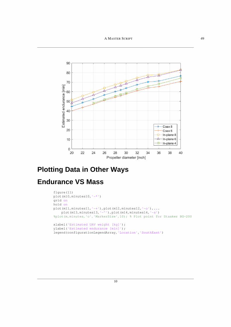
Endurance was plotted against propeller size as seen in Figure 4.4. The reader should recall
that the endurance estimate is for maximum flight time and assumes no limit to the depth of
discharge. Generally, the endurance of the configurations increased with propeller diameter.
When controlled for being coaxial or in-plane the endurance increased with number of rotors.
The highest endurance estimate was achieved by the in-plane 8-rotor configuration at 82
minutes and 57 seconds. Compared to this, the in-plane 6-rotor configuration achieved an
endurance estimate of only 0.7% lower. The lowest endurance estimate was achieved by
the coaxial 6-rotor configuration at 39 minutes and 47 seconds. The difference between the
worst and the best performing configurations was largely between 12 and 14 minutes for
matching propeller sizes. The 36 inch propeller from T-MOTOR has a large mass relative to
its size compared to the other propellers. This propeller had a smaller endurance gain per size
increase compared to the other propellers due to it’s mass. The effect is most apparent for the
configurations with eight propellers.
The payload capacity of the UAV is limited by the MTOW set by the regulations which
the Staaker BG-200 falls under. Since the total weight cannot exceed 25 kg, the payload

4.2 CONFIGURATION ANALYSIS 21
FIGURE 4.4: Configurations
capacity becomes the difference between the operating empty weight (OEW) and the MTOW.
The estimated payload capacity in the analysis therefore was defined as 25 kg minus the
estimated UAV mass. The results are presented in Figures 4.5 and 4.6. The in-plane 8-rotor
configuration performed the worst in terms of payload capacity. While this and the in-plane
6-rotor configurations had very similar endurance estimates with 40 inch propellers, the
former had 1.85 kg (31%) less estimated payload than the latter. This was attributed to the
in-plane 8-rotor configuration having the highest number of arms, the longest arms and the
maximum number of rotors since all of these properties increases mass. The mentioned large
mass of the 36 inch propeller and to a lesser extent the 40 inch propeller from T-MOTOR had
a significant impact on the difference in payload capacity between the configurations. This
can be seen in Figure 4.5 as a deviation in performance for the first two data points starting
from the left (40 and 36 inch respectfully) for each configuration. This phenomenon had again
a larger effect on configurations with a higher number of rotors. For endurance of roughly
65 minutes and below, the coaxial 6-rotor configuration had the highest estimated payload
capacity.

22 4 ANALYSIS
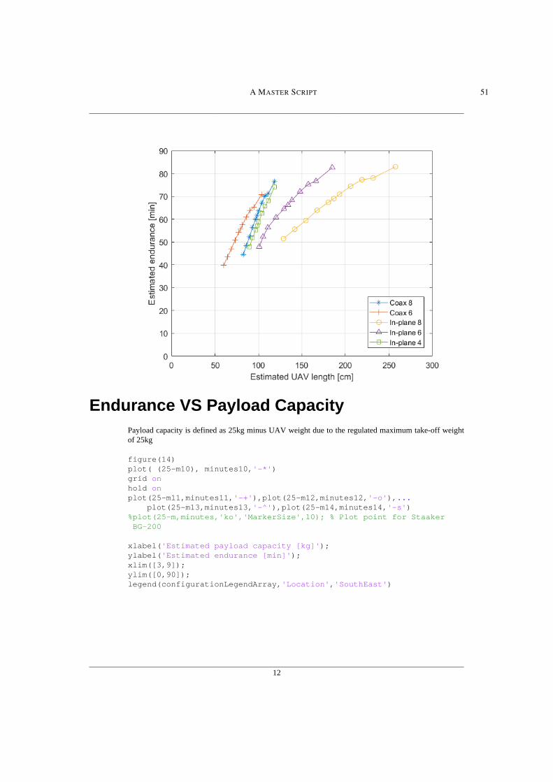
The in-plane 8-rotor and 6-rotor configurations showed the largest estimated UAV sizes
as seen in Figure 4.7 (using Equation 3.11). Therefore, these two designs should perhaps
be avoided if a small UAV size is desirable. The coaxial 8-rotor and the in-plane 4-rotor
configurations have identical sizes (recall that the two smallest propellers were omitted for the
latter configuration), but the latter delivers less estimated endurance for any given propeller
diameter. It also provides less payload capacity for every propeller diameter except 40 inches,
due to the larger and heavier motors. Therefore the in-plane 4-rotor configuration provides no
performance benefits over the coaxial 8-rotor configuration with propellers below 40 inches
based on the present estimations.
FIGURE 4.5: Configuration by Payload Capacity

4.2 CONFIGURATION ANALYSIS 23
FIGURE 4.6: Configuration by mass
FIGURE 4.7: Configuration by Size

24 4 ANALYSIS
4.3 Case Analysis
Three alternative designs were compared to the reference Staaker BG-200 UAV based on the
results of the configuration analysis. One design was selected for maximum endurance. The
maximum endurance for each configuration was achieved with the largest propeller diameter
at 40 inches (see Figure 4.4). As previously mentioned, the in-plane 8-rotor configuration
achieved the overall highest estimated endurance. However, since the 40 inch in-plane 6-rotor
design estimate was only 0.7% lower, and the design was significantly smaller and lighter,
this configuration was instead chosen for the case analysis.
The next design was chosen to maximise payload, with the criteria that the endurance must be
at least 80% of the reference UAV. The resulting configuration was coaxial with 6 rotors and
26 inch propellers. The last design was meant to be a balanced design that would increase
endurance while still having good payload capacity and a manageable size. When appropriate
criteria were applied, three designs with similar performance were found from three different
configurations. Therefore a separate analysis was done for these three designs.
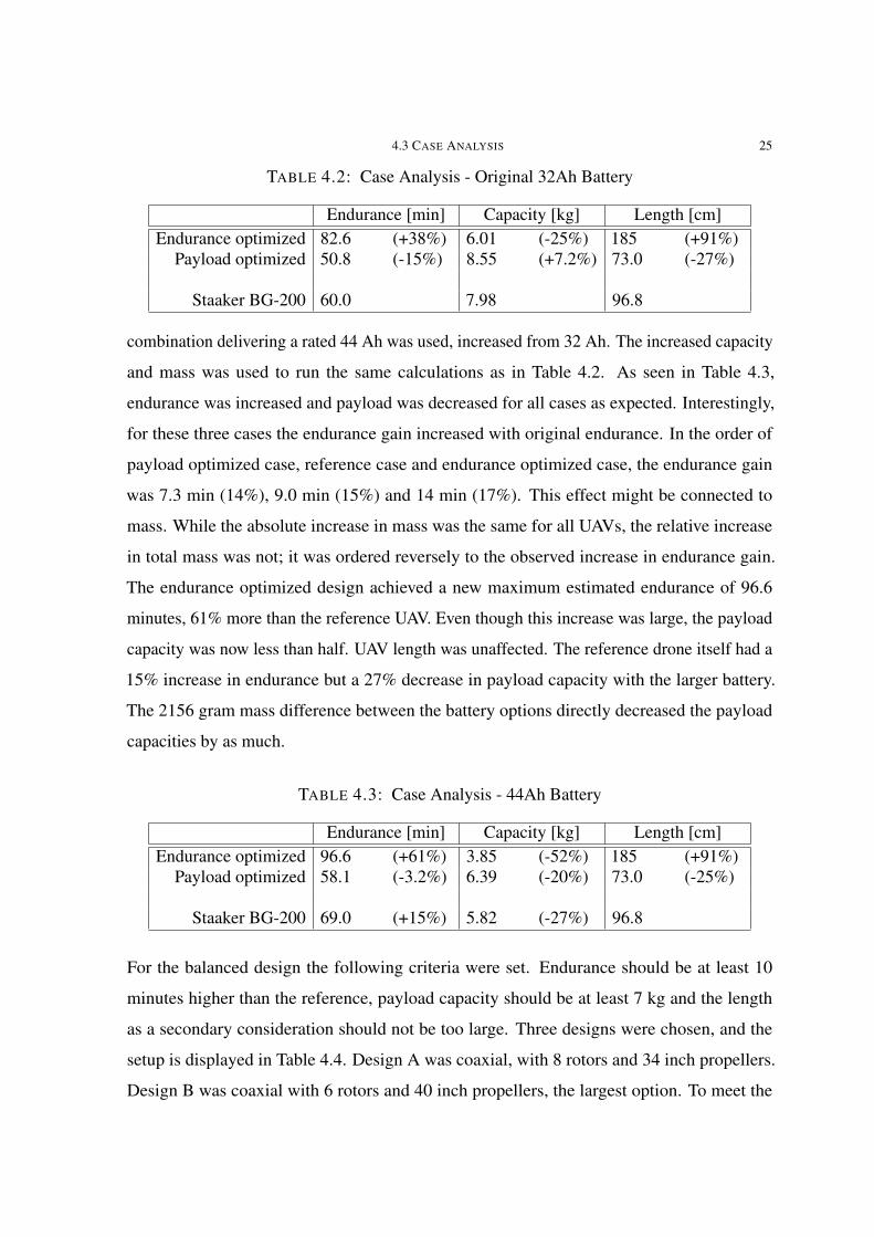
The results of the first comparison are presented in Table 4.2. A maximum estimated endurance
of 82.6 minutes was found for the endurance optimized design, a large increase over the
reference UAV. This design involved large compromises however. The length estimate of the
UAV was almost double that of the Staaker BG-200, amd the payload capacity decreased by 2
kg. The payload optimized design only achieved a 7.2% increase in payload while sacrificing
15% endurance. Advantageously, the estimated length of this design was 27% smaller than
the reference. While the length was here used to compare the size of the UAVs, one should
not forget that the two dimensional size of the UAV changes with an exponent of two. The
reason that a one dimensional estimate was used is because the geometry changes every time
the number of arms changes, while the length can be modeled with a single formula for all
configurations except the thee-armed ones.
To perform a simple analysis of the significance of the battery size, the original battery
specifications were replaced by the next size available from seller MaxAmps. A battery
4.3 CASE ANALYSIS 25
TABLE 4.2: Case Analysis - Original 32Ah Battery
Endurance [min] Capacity [kg] Length [cm]Endurance optimized 82.6 (+38%) 6.01 (-25%) 185 (+91%)
Payload optimized 50.8 (-15%) 8.55 (+7.2%) 73.0 (-27%)
Staaker BG-200 60.0 7.98 96.8
combination delivering a rated 44 Ah was used, increased from 32 Ah. The increased capacity
and mass was used to run the same calculations as in Table 4.2. As seen in Table 4.3,
endurance was increased and payload was decreased for all cases as expected. Interestingly,
for these three cases the endurance gain increased with original endurance. In the order of
payload optimized case, reference case and endurance optimized case, the endurance gain
was 7.3 min (14%), 9.0 min (15%) and 14 min (17%). This effect might be connected to
mass. While the absolute increase in mass was the same for all UAVs, the relative increase
in total mass was not; it was ordered reversely to the observed increase in endurance gain.
The endurance optimized design achieved a new maximum estimated endurance of 96.6
minutes, 61% more than the reference UAV. Even though this increase was large, the payload
capacity was now less than half. UAV length was unaffected. The reference drone itself had a
15% increase in endurance but a 27% decrease in payload capacity with the larger battery.
The 2156 gram mass difference between the battery options directly decreased the payload
capacities by as much.
TABLE 4.3: Case Analysis - 44Ah Battery
Endurance [min] Capacity [kg] Length [cm]Endurance optimized 96.6 (+61%) 3.85 (-52%) 185 (+91%)
Payload optimized 58.1 (-3.2%) 6.39 (-20%) 73.0 (-25%)
Staaker BG-200 69.0 (+15%) 5.82 (-27%) 96.8
For the balanced design the following criteria were set. Endurance should be at least 10
minutes higher than the reference, payload capacity should be at least 7 kg and the length
as a secondary consideration should not be too large. Three designs were chosen, and the
setup is displayed in Table 4.4. Design A was coaxial, with 8 rotors and 34 inch propellers.
Design B was coaxial with 6 rotors and 40 inch propellers, the largest option. To meet the

26 4 ANALYSIS
thrust-to-weight ratio criteria of at least 2, this design used the heavier U10II KV100 motors.
Design C was an in-plane 4-rotor configuration, also with 40 inch propellers. This design
used the heaviest motors of this study, the U12II KV120. The original 16 Ah batteries were
used.
Since the performance of the three designs were so similar, the sum of the off-the-shelf prices
for the propulsion system for each design was found, excluding the battery. The prices were
taken from the T-MOTORS web store 4th of June 2020. On the web store they recommend
a larger ESC (see 2.1) for the U12II motor which is reasonable when only four motors are
producing the necessary thrust. Therefore the difference in price between the ESC used for
the other designs and the mentioned larger ESC was added to the summed price of design
C. Note that the change in mass for the ESC was not considered. The results are presented
in Table 4.5. Most interestingly, both design B and C amounted to lower costs compared
to the components used in the reference UAV Staaker BG-200. The price of the design C
components amounted to $3956, which was $1892 less than BG-200. The coupled endurance
estimate was 14.1 minutes (23%) more than reference, with a decrease in payload capacity
and an increased UAV length. The UAV sizes of all cases are compared in Figure 4.8.
TABLE 4.4: Case Analysis - Balanced Design Setup
Configuration dP [in] Motor ESC [in]Design A Coaxial 8 34 U8II KV100 Alpha 60V HVDesign B Coaxial 6 40 U10II KV100 Alpha 60V HVDesign C In-plane 4 40 U12II KV120 Alpha 120V HV
Staaker BG-200 Coaxial 8 28 U8II KV100 Alpha 60V HV
TABLE 4.5: Case Analysis - Balanced Design Results
Endurance [min] Capacity [kg] Length [cm] Partial priceDesign A 70.2 7.55 108 $6400Design B 70.7 7.42 103 $5394Design C 74.1 7.17 118 $3956
Staaker BG-200 60.0 7.98 96.8 $5848

4.3 CASE ANALYSIS 27
FIGURE 4.8: Size Comparison

CHAPTER 5
Discussion and Conclusion
5.1 Discussion
The configuration analysis showed that the size of the UAV is sensitive to both the configura-
tion and the propeller size. It also showed that endurance is sensitive to the same factors. The
configurations with coaxial rotors achieved lower endurance estimates compared to the in-
plane rotor configurations when controlling for number of rotors and propeller diameter. This
was expected due to the efficiency loss that occurs in the interaction between the upper and
lower propellers for coaxial rotors. The mass of the arms used in the coaxial configurations is
lower, because they are shorter in length and halved in quantity. This decrease in mass was
not enough to make up for the efficiency loss.
At first the in-plane 4-rotor configuration was not considered advantageous because for each
rotor diameter it displayed a lower endurance for the same UAV size as the coaxial 8-rotor
configuration, while also generally having a smaller payload capacity. In the case analysis
however, the in-plane 4-rotor proved to be superior in component pricing. Design C achieved
better endurance for a significantly lower component price compared to the reference UAV
Staaker BG-200, at the cost of size and payload capacity. A designer could choose smaller
propellers for the same configuration to obtain the desired size and payload capacity. This
would decrease the endurance, but would further decrease the component cost. The coaxial
6-rotor configuration cost less than the coaxial 8-rotor configuration as well. The in-plane
8-rotor configuration performed poorly in terms of size and payload capacity, while being
largely matched in endurance by the in-plane 6-rotor configuration. The former had a lower
power consumption per thrust due to the highest number of rotors, but the added mass28

5.1 DISCUSSION 29
associated with the rotors and the eight arms increased the necessary thrust to hover. This
allowed the in-plane 6-rotor configuration to achieve a similar peak endurance with a smaller
rotor disk area.
Except for the in-plane 8-rotor configuration, all other configurations displayed unique
benefits. In-plane 6 achieved high endurance and in-plane 4 achieved low cost. Coaxial 6
achieved small size and low weight, and coaxial 8 at some limited points achieved the highest
endurance for a given size and payload capacity. It can be argued that if the 36 inch and the
40 inch propellers did not deviate from the trend of the other propellers in terms of mass then
the coaxial 8 might have been surpassed by the coaxial 6-rotor configuration. In Figure 4.5,
excluding the two largest propellers, the coaxial 6-rotor configuration seems to maintain the
gap in payload capacity to the coaxial 8-rotor data. Figure 4.7 suggests that the curves for the
same two configurations may cross for some larger propeller size, although they might not.
Therefore it is possible that the coaxial 6-rotor could achieve the best endurance for any given
UAV size or payload capacity if the propellers were more carefully designed.
5.1.1 Improvement Suggestions
The recommendations for optimizing the endurance of the existing Staaker BG-200 UAV are
as follows. Increasing the propeller size will generally improve the endurance at the cost of
payload capacity, UAV size and price. A coaxial 6-rotor configuration should be considered
as the estimations in this thesis suggest it generally has the highest payload capacity and the
smallest UAV size for a given endurance target. The coaxial 6-rotor design in the case analysis
also had a less costly motor and propeller combination than the Staaker BG-200. A 4-rotor
configuration should also be considered if some performance can be sacrificed, as the cost of
the propulsion system for this configuration is meaningfully lower than the coaxial 8-rotor
configuration used today. An in-plane 4-rotor design with 40 inch propellers is proposed with
an estimated endurance improvement of 14.1 minutes (23%) and a $1892 decrease in cost,
with 0.81 kg (10%) decreased payload capacity and 14 cm (14%) increased UAV length.

30 5 DISCUSSION AND CONCLUSION
5.1.2 Limitations
The present thesis has assumed that the motors will produce their rated thrust using any
propeller size. However, larger propellers have higher moment of inertia and requires more
torque to operate. It is possible that some of the motor-propeller combinations used in Chapter
4 are not appropriate. The parallel Bachelor thesis noticed in the experiments that the U8II
KV100 motor produced more heat when pared with the largest propeller tested, which was
32 inches in diameter. Heat generation is synonymous with efficiency loss. This effect was
observed at maximum throttle, and not at a normal hover/cruising throttle. The extent of
this effect with further increased propeller size is unknown, and could have an impact on the
performance of the designs.
Perhaps the most significant limitation of the present study is the assumption that the propul-
sion system efficiency stays constant for all propellers and motors used. Generally, this effi-
ciency increases with RPM [2], [21], [22] while holding propeller diameter fixed. Ramasamy
[23] found that FM increased with Reynolds number (Re), where Re increases with RPM and
chord length. The study explained that this is expected because "viscous parasitic drag losses
which do not contribute toward thrust generation are more prominent at low Re" [23]. This
means that when Re is increased by increasing RPM, the ratio between useful and non-useful
drag increases. When the total weight of the UAV is close to constant, the required thrust is
close to constant and the pitch-to-diameter ratio is constant, increasing the propeller diameter
will reduce the RPM necessary to hover.
While the reduction in ideal power consumption due to a larger rotor disk area has been
captured by the model used in this thesis, the change in propeller and motor efficiency due to
a reduction in RPM has not. The necessary RPM also changes with thrust, but the change in
thrust has been limited throughout the analysis, where the largest mass variation can be found
for the largest designs that have been considered impractical. The differences in efficiency
between different propellers and motors have also not been captured. The experimental data
from the Bachelor thesis showed very similar efficiencies around hover thrust when comparing
the 28 inch and the 32 inch propellers, but the range of propeller diameters was much larger

5.1 DISCUSSION 31
in the present study. In hindsight, the efficiency should not be assumed to be fixed when the
change in RPM is unknown and a variety of components are used.
Ideally the range of components should be tested experimentally. To achieve accurate results
without testing every propeller-motor combination the following should be determined: For
each motor; the power efficiency as a function of torque and rotational speed - For each
propeller the torque, rotational speed and the Figure of Merit as functions of thrust. These
could be implemented in the MATLAB script used for this thesis or in a numerical solver.
Component manufacturers have data sheets with varying levels of detail, but these are prone
to be inaccurate and inflated, and they do not form a rigorous foundation for analysis. Other
known limitations of the present analysis are not expected to have a large impact on the result,
although they could affect the relation between closely matched designs. These limitations
include the constant battery capacity model, excluding adjacent rotor interaction, fixed arm
mass-per-length, inaccuracies in the data gathered from the manufacturer and assuming no
secondary power consumption.
Undoubtedly, the problem of optimizing endurance of a multirotor UAV is complex with
interdependent factors. These factors involve several fields of technology, and the designer
must balance conflicting goals when searching for the most beneficial solution. The analysis
done in the present thesis included multiple factors, and an attempt was done to account for
multiple goals. A more holistic analysis can be done by using a multidisciplinary design
optimization (MDO) method as done in Reference [10]. Here, a series of factors can be
considered simultaneously, such as propeller blade design, structural integrity, electrical
system design and propulsion system design. A solution can be solved numerically to give a
design that balances the interdependent parameters and goals. Such a method requires deep
as well as broad knowledge by the developer(s), but is ultimately very useful for this complex
problem.

32 5 DISCUSSION AND CONCLUSION
5.2 Conclusion
This thesis has studied how the endurance of multirotor UAVs can be optimized. The scientific
goals were largely met. A broad overview was given for the identified factors that influence
endurance. A set of critical factors were quantified and improvement suggestions to the
Staaker BG-200 were made.
Endurance was found to increase with increasing propeller diameter, increasing number of
propellers and decreasing mass. The highest endurance estimate achieved without replacing
the battery was 82 minutes and 57 seconds, a 38% increase over Staaker BG-200. This
in-plane 8-rotor configuration was relatively large and had a significantly decreased payload
capacity. The coaxial 6-rotor configuration had the smallest size and the highest payload
capacity of the configurations when controlled for propeller size. In the case analysis, the
relative endurance gain from increasing the battery capacity from 32 AH to 44 Ah was between
14% to 17%. The payload capacity was lowered by the battery weight difference of roughly
2.2 kg. When propulsion system prices were considered, the in-plane 4-rotor configuration
with 40 inch propellers amounted to $1892 less than the reference UAV while having an
estimated endurance increase of 14.1 minutes (23%). Payload capacity was decreased by 0.81
kg (10%) and the UAV length increased by 14 cm (14%) for this design.
The recommendations for optimizing the endurance of the existing Staaker BG-200 UAV are
to consider increasing propeller size, consider a coaxial 6-rotor configuration for performance
or consider an in-plane 4-rotor configuration for its lower cost. In particular, the 4-rotor con-
figuration with 40 inch propellers is proposed with the aforementioned benefits of increased
endurance and decreased cost.
A significant limitation of the estimates done is the assumption that the ratio between ideal
and actual power consumption stays constant when varying the propellers, motors and the
thrust. This assumption may disproportionally benefit the larger propellers.

5.3 FUTURE WORK 33
5.3 Future Work
A set of recommendations follows for future work on optimizing multirotor UAVs based on
the experience and knowledge gathered in the present work. A dynamic model for the ratio of
ideal to actual hover power should be included in future studies. Experimental data should
be gathered for components considered to avoid inaccuracy and inflation of data reported
by the manufacturers. To provide a holistic solution to this multifactored interdependent
problem, a multidisciplinary design optimization method should be used. Such methods
are intended to evaluate a series of parameters simultaneously, and is very well suited for
this application. The interference between adjacent coaxial rotor pairs has to the authors
knowledge not been studied. Experiments on the matter could reveal an ideal ratio between
in-plane separation distance and propeller diameter for such systems. Limiting the UAV size
at the cost of efficiency is perhaps the main advantage of a coaxial configuration. Therefore
the option of using in-plane thee-bladed propellers in place of coaxial rotors could provide
the same qualitative benefit, which warrants further quantitative analysis.

Bibliography
[1] M. Gatti, F. Giulietti and M. Turci, ‘Maximum endurance for battery-powered rotary-
wing aircraft’, Aerospace Science and Technology, vol. 45, pp. 174–179, 2015. DOI:
10.1016/j.ast.2015.05.009.
[2] Y. Mulgaonkar, M. Whitzer, B. Morgan, C. M. Kroninger, A. M. Harrington and V.
Kumar, ‘Power and Weight Considerations in Small, Agile Quadrotors’, in Micro- and
Nanotechnology Sensors, Systems, and Applications VI, T. George, M. S. Islam and
A. K. Dutta, Eds., International Society for Optics and Photonics, vol. 9083, SPIE,
2014, pp. 376–391. DOI: 10.1117/12.2051112.
[3] D. Beekman, ‘Micro air vehicle endurance versus battery size’, Proceedings of SPIE -
The International Society for Optical Engineering, vol. 7679(767910), Apr. 2010. DOI:
10.1117/12.849564.
[4] J. Whitney and R. Wood, ‘Conceptual design of flapping-wing micro air vehicles’,
Bioinspiration & biomimetics, vol. 7(3):036001, Apr. 2012. DOI: 10.1088/1748-
3182/7/3/036001.
[5] Y. Mulgaonkar and V. Kumar, ‘Autonomous charging to enable long-endurance mis-
sions for small aerial robots’, Jun. 2014, 90831S-1-90831S–15. DOI: 10.1117/12.
2051111.
[6] N. A. Vu, D. K. Dang and T. [ Dinh], ‘Electric propulsion system sizing methodology
for an agriculture multicopter’, Aerospace Science and Technology, vol. 90, pp. 314–
326, 2019, ISSN: 1270-9638. DOI: 10.1016/j.ast.2019.04.044.
[7] S. Prior, Optimizing Small Multi-Rotor Unmanned Aircraft: A Practical Design Guide.
Sep. 2018, pp. 5–10, ISBN: 9780429428364. DOI: 10.1201/9780429428364.
34

BIBLIOGRAPHY 35
[8] O. Cleynen. (). Wing profile nomenclature, [Online]. Available: https://en.
wikipedia . org / wiki / Airfoil # /media / File : Wing _ profile _
nomenclature.svg. (accessed: 28.05.2020).
[9] J. Winslow, M. Benedict, V. Hrishikeshavan and I. Chopra, ‘Design, development, and
flight testing of a high endurance micro quadrotor helicopter’, vol. 8(3), Jan. 2016,
pp. 155–169.
[10] O. Gur and A. Rosen, ‘Optimizing electric propulsion systems for uavs’, vol. 6(4), Sep.
2008, ISBN: 978-1-60086-982-2. DOI: 10.2514/6.2008-5916.
[11] (). T-motor webstore, [Online]. Available: http://store-en.tmotor.com/.
(accessed: 04.06.2020).
[12] J. M. F. Fischer, ‘Structural response analysis of a composite multirotor airframe’,
Master’s thesis, University of Stavanger, 2019. [Online]. Available: http://hdl.
handle.net/11250/2620903.
[13] B. Theys, G. Dimitriadis and P. Hendrick, ‘Influence of propeller configuration on
propulsion system efficiency of multi-rotor unmanned aerial vehicles’, Jun. 2016,
pp. 195–201. DOI: 10.1109/ICUAS.2016.7502520.
[14] A. Abdilla, A. Richards and S. Burrow, ‘Power and endurance modelling of battery-
powered rotorcraft’, 2015 IEEE/RSJ International Conference on Intelligent Robots
and Systems (IROS), pp. 675–680, 2015. DOI: 10.1109/IROS.2015.7353445.
[15] J. G. Leishman, Principles of Helicopter Aerodynamics. Cambridge University Press,
2000, pp. 36–52.
[16] C. P. Coleman, ‘A survey of theoretical and experimental coaxial rotor aerodynamic
research’, National Aeronautics and Space Administration, 1997.
[17] J. Leishman and M. Syal, ‘Figure of merit definition for coaxial rotors’, Journal of the
American Helicopter Society, vol. 53, pp. 290–300, Jul. 2008. DOI: 10.4050/JAHS.
53.290.
[18] A. M. Harrington, ‘Optimal propulsion system design for a micro quadrotor’, p. 81,
2011.
[19] Q. Quan, Introduction to Multicopter Design and Control. Springer Nature Singapore,
Jun. 2017, pp. 59–67. DOI: 10.1007/978-981-10-3382-7.

36 BIBLIOGRAPHY
[20] M. Brazinskas, S. Prior and J. Scanlan, ‘An empirical study of overlapping rotor
interference for a small unmanned aircraft propulsion system’, Aerospace, vol. 3, p. 32,
Oct. 2016. DOI: 10.3390/aerospace3040032.
[21] D. Lawrence and K. Mohseni, ‘Efficiency analysis for long duration electric mavs’,
Sep. 2005, ISBN: 978-1-62410-069-7. DOI: 10.2514/6.2005-7090.
[22] A. Harrington and C. Kroninger, ‘Endurance bounds of aerial systems’, vol. 9083(90831R),
Jun. 2014, 90831R. DOI: 10.1117/12.2053790.
[23] M. Ramasamy, ‘Hover performance measurements toward understanding aerodynamic
interference in coaxial, tandem, and tilt rotors’, Journal of the American Helicopter
Society, vol. 60, Jul. 2015. DOI: 10.4050/JAHS.60.032005.

Appendices
37


APPENDIX A
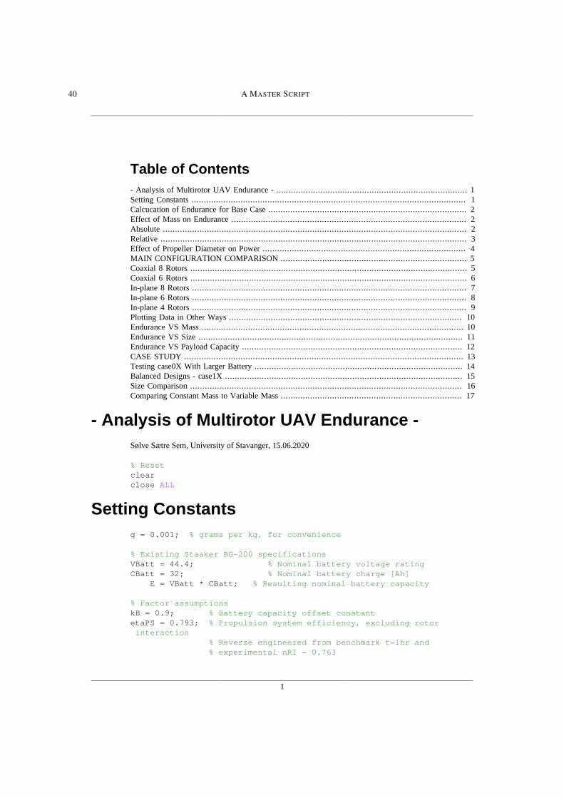
Master Script
Here follows the master script that executed all the calculations and plot generation for the
analysis in this thesis. The script uses three functions, which are presented in Appendices B,
C and D.
39
1
Table of Contents- Analysis of Multirotor UAV Endurance - .............................................................................. 1Setting Constants ................................................................................................................ 1Calcucation of Endurance for Base Case ................................................................................. 2Effect of Mass on Endurance ................................................................................................ 2Absolute ............................................................................................................................ 2Relative ............................................................................................................................. 3Effect of Propeller Diameter on Power ................................................................................... 4MAIN CONFIGURATION COMPARISON ............................................................................ 5Coaxial 8 Rotors ................................................................................................................. 5Coaxial 6 Rotors ................................................................................................................. 6In-plane 8 Rotors ................................................................................................................ 7In-plane 6 Rotors ................................................................................................................ 8In-plane 4 Rotors ................................................................................................................ 9Plotting Data in Other Ways ............................................................................................... 10Endurance VS Mass ........................................................................................................... 10Endurance VS Size ............................................................................................................ 11Endurance VS Payload Capacity .......................................................................................... 12CASE STUDY .................................................................................................................. 13Testing case0X With Larger Battery ..................................................................................... 14Balanced Designs - case1X ................................................................................................. 15Size Comparison ............................................................................................................... 16Comparing Constant Mass to Variable Mass .......................................................................... 17
- Analysis of Multirotor UAV Endurance -Sølve Sætre Sem, University of Stavanger, 15.06.2020
% Resetclearclose ALL
Setting Constantsg = 0.001; % grams per kg, for convenience
% Existing Staaker BG-200 specificationsVBatt = 44.4; % Nominal battery voltage ratingCBatt = 32; % Nominal battery charge [Ah] E = VBatt * CBatt; % Resulting nominal battery capacity
% Factor assumptionskB = 0.9; % Battery capacity offset constantetaPS = 0.793; % Propulsion system efficiency, excluding rotor interaction % Reverse engineered from benchmark t=1hr and % experimental nRI = 0.763
40 A MASTER SCRIPT

2
Calcucation of Endurance for Base CaseStaaker BG-200
% ConfigurationNR = 8; % Number of rotorsdP = 28; % Propeller diameter in inchesisCoax = 1; % 1 if UAV has coaxial rotors, 0 if otherwise
m = mass(NR, dP, isCoax);P = PMulti(NR, dP, m, etaPS, isCoax);t = kB * E ./P;
L = DroneSize(NR,dP,isCoax);
minutes = t*60;disp('Estimated endurance of base case in minutes is:');disp([num2str(round(minutes)),' minutes']); disp(' ');
Estimated endurance of base case in minutes is:60 minutes
Effect of Mass on Endurance
Absolutem2_Delta = 125*g;m2 = 10:m2_Delta:25; % Varying mass from 12kg to MTOW 25kg in steps of 125g
P2 = PMulti(NR, dP, m2, etaPS, isCoax);t2 = kB * E ./P2;minutes2 = t2.*60;
figure(1);plot(m2, minutes2);xlim([m2(1),m2(end)])ylim([0,120]);xlabel('Take-off weight [kg]');ylabel('Estimated endurance [min]');grid on
disp(['Estimated endurance at MTOW is ', num2str(minutes2(end))]); disp(' ');
Estimated endurance at MTOW is 33.7268
A MASTER SCRIPT 41
3
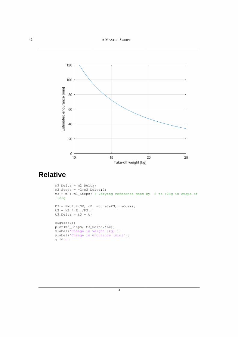
Relativem3_Delta = m2_Delta;m3_Steps = -2:m3_Delta:2;m3 = m + m3_Steps; % Varying reference mass by -2 to +2kg in steps of 125g
P3 = PMulti(NR, dP, m3, etaPS, isCoax);t3 = kB * E ./P3;t3_Delta = t3 - t;
figure(2);plot(m3_Steps, t3_Delta.*60);xlabel('Change in weight [kg]');ylabel('Change in endurance [min]');grid on
42 A MASTER SCRIPT

4
Effect of Propeller Diameter on Powerm4 = 25; % Maximum Take-Off Weight (MTOW) % Excluding effects of variable mass which depending on dP
NR4 = 8; % Base case from BG-200isCoax4 = true; %
dP4 = 20:1:40; % Varying propeller diameter from 20 to 20*2 inches
P4 = PMulti(NR4, dP4, m4, etaPS, isCoax4); % Associated hover power
%P_MTOW = PMulti(NR4, 20, m4, FM, isCoax4); % Power for reference- 20" prop%P4_Normalized = P4/P_MTOW; % Hover power compared to base case%dP4_Normalized = dP4/20;
% Plotting theoretical hover power vs propeller diameterfigure(4);%plot(dP4_Normalized, P4_Normalized);plot(dP4,P4);ylim([0,4000]);xlabel('Propeller diameter [inch]');
A MASTER SCRIPT 43
5
ylabel('Estimated hover power [W]');grid on
MAIN CONFIGURATION COMPARISON
Coaxial 8 RotorsNR10 = 8; % Number of rotorsdP10 = [20, 22, 24, 26, 28, 29, 30, 32, 34, 36, 40]; % Propeller diameter in inchesisCoax10 = 1; % 1 if UAV has coaxial rotors, 0 if otherwise
% Calcucation of endurancem10 = mass(NR10, dP10, isCoax10);P10 = PMulti(NR10, dP10, m10, etaPS, isCoax10);t10 = kB * E ./P10;
% Calculation of sizeL10 = DroneSize(NR10,dP10,isCoax10);
minutes10 = t10*60; % Endurance in minutes, from hours
figure(10)plot(dP10,minutes10,'-*')xlabel('Propeller diameter [inch]');
44 A MASTER SCRIPT

6
ylabel('Estimated endurance [min]');ylim([0,90]);configurationLegendArray{1} = 'Coax 8';
grid onhold on
Coaxial 6 RotorsNR11 = 6;dP11 = dP10; % Same vector of propeller diameters as previous caseisCoax11 = 1;
m11 = mass(NR11, dP11, isCoax11);P11 = PMulti(NR11, dP11, m11, etaPS, isCoax11);t11 = kB * E ./P11;
L11 = DroneSize(NR11,dP11,isCoax11);
minutes11 = t11*60;
plot(dP11,minutes11,'-+')configurationLegendArray{2} = 'Coax 6';
A MASTER SCRIPT 45

7
In-plane 8 RotorsNR12 = 8;dP12 = dP10;isCoax12 = 0;
m12 = mass(NR12, dP12, isCoax12);P12 = PMulti(NR12, dP12, m12, etaPS, isCoax12);t12 = kB * E ./P12;
L12 = DroneSize(NR12,dP12,isCoax12);
minutes12 = t12*60;
plot(dP12,minutes12,'-o')configurationLegendArray{3} = 'In-plane 8';
46 A MASTER SCRIPT

8
In-plane 6 RotorsNR13 = 6;dP13 = dP10;isCoax13 = 0;
m13 = mass(NR13, dP13, isCoax13);P13 = PMulti(NR13, dP13, m13, etaPS, isCoax13);t13 = kB * E ./P13;
L13 = DroneSize(NR13,dP13,isCoax13);
minutes13 = t13*60;
plot(dP13,minutes13,'-^')configurationLegendArray{4} = 'In-plane 6';
A MASTER SCRIPT 47

9
In-plane 4 RotorsNR14 = 4;dP14 = dP10(3:end); % Excluding 20 and 22 inch as they are not % rated for enough thrust to reach sum 50kgisCoax14 = 0;
m14 = mass(NR14, dP14, isCoax14);P14 = PMulti(NR14, dP14, m14, etaPS, isCoax14);t14 = kB * E ./P14;
L14 = DroneSize(NR14,dP14,isCoax14);minutes14 = t14*60;
plot(dP14,minutes14,'-s')configurationLegendArray{5} = 'In-plane 4';
% Plot point for Staaker BG-200%plot(dP,minutes,'o','MarkerSize',10);
legend(configurationLegendArray,'Location','SouthEast')
48 A MASTER SCRIPT
10
Plotting Data in Other Ways
Endurance VS Massfigure(11)plot(m10,minutes10,'-*')grid onhold onplot(m11,minutes11,'-+'),plot(m12,minutes12,'-o'),... plot(m13,minutes13,'-^'),plot(m14,minutes14,'-s')%plot(m,minutes,'o','MarkerSize',10); % Plot point for Staaker BG-200
xlabel('Estimated UAV weight [kg]');ylabel('Estimated endurance [min]');legend(configurationLegendArray,'Location','SouthEast')
A MASTER SCRIPT 49

11
Endurance VS Sizefigure(12)plot(L10*100,minutes10,'-*')grid onhold onplot(L11*100,minutes11,'-+'),plot(L12*100,minutes12,'-o'),... plot(L13*100,minutes13,'-^'),plot(L14*100,minutes14,'-s')%plot(L,minutes,'ko','MarkerSize',10); % Plot point for Staaker BG-200ylim([0,90]);xlim([0,300]);xlabel('Estimated UAV length [cm]');ylabel('Estimated endurance [min]');legend(configurationLegendArray,'Location','SouthEast')
50 A MASTER SCRIPT
12
Endurance VS Payload CapacityPayload capacity is defined as 25kg minus UAV weight due to the regulated maximum take-off weightof 25kg
figure(14)plot( (25-m10), minutes10,'-*')grid onhold onplot(25-m11,minutes11,'-+'),plot(25-m12,minutes12,'-o'),... plot(25-m13,minutes13,'-^'),plot(25-m14,minutes14,'-s')%plot(25-m,minutes,'ko','MarkerSize',10); % Plot point for Staaker BG-200
xlabel('Estimated payload capacity [kg]');ylabel('Estimated endurance [min]');xlim([3,9]);ylim([0,90]);legend(configurationLegendArray,'Location','SouthEast')
A MASTER SCRIPT 51

13
CASE STUDY% Base reference case (Staaker BG-200)case00 = [minutes, m, L, NR, dP, isCoax];
% 13(end) Max endurance: In-plane 6 - 40inch propcase01 = [minutes13(end), m13(end), L13(end), 6, dP13(end), 0];
% 11(4) Min weight w/ min 80% endurance: Coax 6 - 26inchp02 = 4; % using propeller number 4 (26 inch) from the coax 6 configcase02 = [minutes11(p02), m11(p02), L11(p02), 6, dP11(p02), 1];
case0X = [ case01; case02; case00]; % Combined matrix% Example: case0X(:,4) gives NR for all cases
% Percentages, rounded to two decimals: % EndurancePer0X_t = round( 100*( case0X(:,1)' - minutes)./minutes, 2); % PayloadPer0X_mp = round( 100*( (25- case0X(:,2)') - (25-m) )./ (25-m), 2); % SizePer0X_L = round( 100*( case0X(:,3)' - L )./ L, 2);
disp('CASE STUDY: Original battery - value (%)');disp(' ');
52 A MASTER SCRIPT

14
disp('Endurance optimized');disp(['t = ',num2str(case01(1)),' (',num2str(Per0X_t(1)),')',... '. Payload = ',num2str(25- case01(2)),' (',num2str(Per0X_mp(1)),')',... '. L = ',num2str(case01(3)),' (',num2str(Per0X_L(1)),')']);disp(' ');disp('Payload optimized');disp(['t = ',num2str(case02(1)),' (',num2str(Per0X_t(2)),')',... '. Payload = ',num2str(25- case02(2)),' (',num2str(Per0X_mp(2)),')',... '. L = ',num2str(case02(3)),' (',num2str(Per0X_L(2)),')']);disp(' ');disp('Reference design');disp(['t = ',num2str(case00(1)),... '. Payload = ',num2str(25- case00(2)),... '. L = ',num2str(case00(3))]);disp(' ');
CASE STUDY: Original battery - value (%) Endurance optimizedt = 82.5792 (37.59). Payload = 6.006 (-24.7). L = 1.8478 (90.85) Payload optimizedt = 50.8136 (-15.34). Payload = 8.5499 (7.2). L = 0.72995 (-24.61) Reference designt = 60.0186. Payload = 7.9758. L = 0.96817
Testing case0X With Larger BatteryNR50 = case0X(:,4)'; % Number of rotorsdP50 = case0X(:,5)'; % Propeller diameter in inchesisCoax50 = case0X(:,6)'; % 1 if UAV has coaxial rotors, 0 if otherwise
% Calcucation of endurance
m50_std = case0X(:,2)';m50 = m50_std + 2.156; % Larger batteryE50 = VBatt*44; % Larger battery, 44Ah
P50 = PMulti(NR50, dP50, m50, etaPS, isCoax50);t50 = kB * E50 ./P50;
minutes50 = t50*60;
payload50 = 25 - m50;
disp('CASE STUDY: Larger batteries - value (%)')
% Percentages, rounded to two decimals:
A MASTER SCRIPT 53
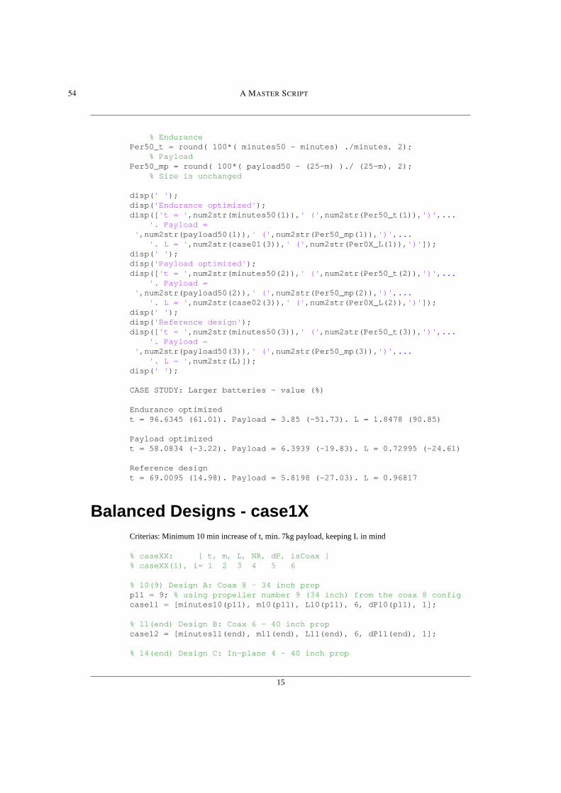
15
% EndurancePer50_t = round( 100*( minutes50 - minutes) ./minutes, 2); % PayloadPer50_mp = round( 100*( payload50 - (25-m) )./ (25-m), 2); % Size is unchanged
disp(' ');disp('Endurance optimized');disp(['t = ',num2str(minutes50(1)),' (',num2str(Per50_t(1)),')',... '. Payload = ',num2str(payload50(1)),' (',num2str(Per50_mp(1)),')',... '. L = ',num2str(case01(3)),' (',num2str(Per0X_L(1)),')']);disp(' ');disp('Payload optimized');disp(['t = ',num2str(minutes50(2)),' (',num2str(Per50_t(2)),')',... '. Payload = ',num2str(payload50(2)),' (',num2str(Per50_mp(2)),')',... '. L = ',num2str(case02(3)),' (',num2str(Per0X_L(2)),')']);disp(' ');disp('Reference design');disp(['t = ',num2str(minutes50(3)),' (',num2str(Per50_t(3)),')',... '. Payload = ',num2str(payload50(3)),' (',num2str(Per50_mp(3)),')',... '. L = ',num2str(L)]);disp(' ');
CASE STUDY: Larger batteries - value (%) Endurance optimizedt = 96.6345 (61.01). Payload = 3.85 (-51.73). L = 1.8478 (90.85) Payload optimizedt = 58.0834 (-3.22). Payload = 6.3939 (-19.83). L = 0.72995 (-24.61) Reference designt = 69.0095 (14.98). Payload = 5.8198 (-27.03). L = 0.96817
Balanced Designs - case1XCriterias: Minimum 10 min increase of t, min. 7kg payload, keeping L in mind
% caseXX: [ t, m, L, NR, dP, isCoax ]% caseXX(i), i= 1 2 3 4 5 6
% 10(9) Design A: Coax 8 - 34 inch propp11 = 9; % using propeller number 9 (34 inch) from the coax 8 configcase11 = [minutes10(p11), m10(p11), L10(p11), 6, dP10(p11), 1];
% 11(end) Design B: Coax 6 - 40 inch propcase12 = [minutes11(end), m11(end), L11(end), 6, dP11(end), 1];
% 14(end) Design C: In-plane 4 - 40 inch prop
54 A MASTER SCRIPT

16
case13 = [minutes14(end), m14(end), L14(end), 6, dP14(end), 1];
case1X = [ case11; case12; case13; case00]; % Combined matrix
disp('CASE STUDY: Balanced designs')disp(' ');disp('Design A: Coax 8 - 34 inch prop');disp([' t = ',num2str(case11(1)),... '. Payload = ',num2str(25- case11(2)),... '. L = ',num2str(case11(3)),... '. Components = $6400']);disp('Design B: Coax 6 - 40 inch prop');disp([' t = ',num2str(case12(1)),... '. Payload = ',num2str(25- case12(2)),... '. L = ',num2str(case12(3)),... '. Components = $5394']);disp('Design C: In-plane 4 - 40 inch prop');disp([' t = ',num2str(case13(1)),... '. Payload = ',num2str(25- case13(2)),... '. L = ',num2str(case13(3)),... '. Components = $3956']);disp(' ');disp('Reference design');disp([' t = ',num2str(case00(1)),... '. Payload = ',num2str(25- case00(2)),... '. L = ',num2str(case00(3)),... '. Components = $5848']);disp(' ');
CASE STUDY: Balanced designs Design A: Coax 8 - 34 inch prop t = 70.2136. Payload = 7.5475. L = 1.0759. Components = $6400Design B: Coax 6 - 40 inch prop t = 70.7389. Payload = 7.4164. L = 1.0344. Components = $5394Design C: In-plane 4 - 40 inch prop t = 74.1176. Payload = 7.1673. L = 1.1837. Components = $3956 Reference design t = 60.0186. Payload = 7.9758. L = 0.96817. Components = $5848
Size Comparisonfigure(40)case_bar = [case01(3), case02(3), case1X(:,3)'];bar(case_bar*100,0.3);% colormap(cool);set(gca, 'XTick', 1:6, 'XTickLabels', {'Endurance',... 'Payload','A','B','C','Staaker BG-200'})ax = gca; ax.XGrid = 'off'; ax.YGrid = 'on'; % Only grid lines in Yylabel('Estimated UAV size [cm]');
A MASTER SCRIPT 55
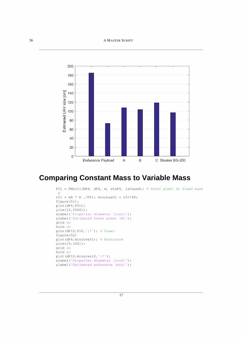
17
Comparing Constant Mass to Variable MassP51 = PMulti(NR4, dP4, m, etaPS, isCoax4); % Hover power at fixed mass mt51 = kB * E ./P51; minutes51 = t51*60;figure(51);plot(dP4,P51);ylim([0,2000]);xlabel('Propeller diameter [inch]');ylabel('Estimated hover power [W]');grid onhold onplot(dP10,P10,':*'); % Powerfigure(52)plot(dP4,minutes51); % Enduranceylim([0,100]);grid onhold onplot(dP10,minutes10,':*');xlabel('Propeller diameter [inch]');ylabel('Estimated endurance [min]');
56 A MASTER SCRIPT
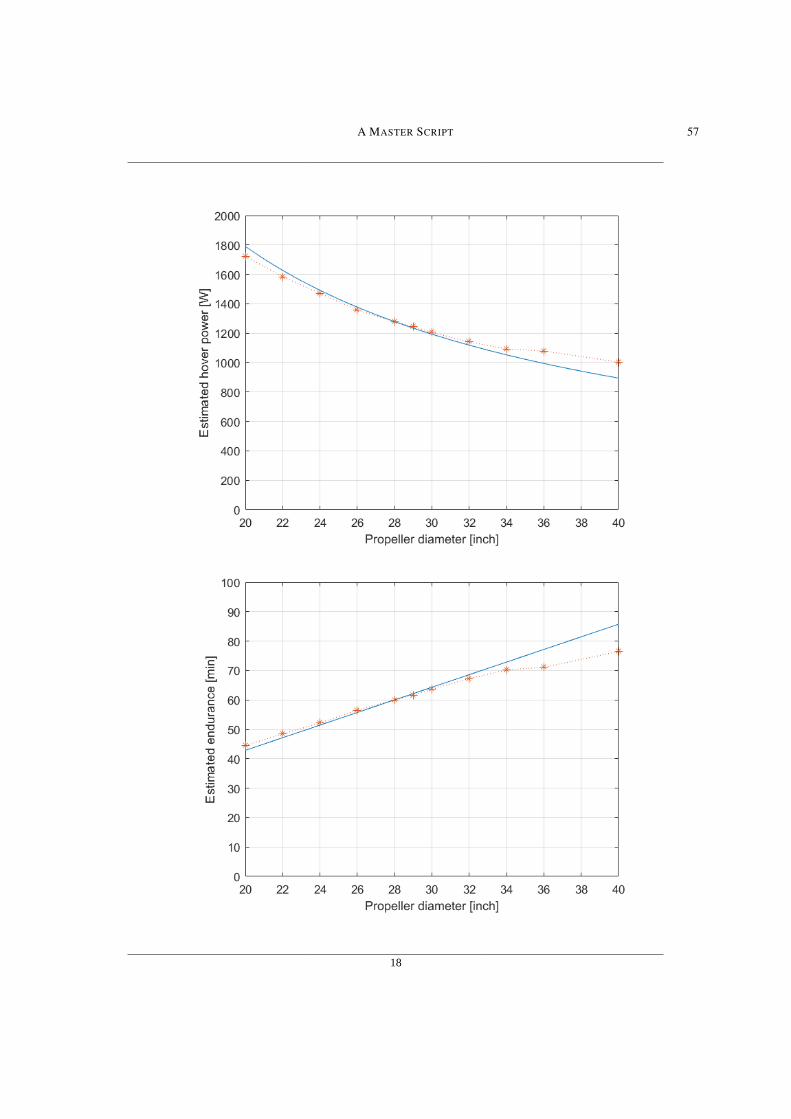
18
A MASTER SCRIPT 57
19
Published with MATLAB® R2016a
58 A MASTER SCRIPT

APPENDIX B
Mass Function
Here follows the script for the first function, which uses the dynamic mass model (Equation
3.4) to estimate the mass of each UAV case.
59

1
Table of Contents ........................................................................................................................................ 1Propeller Mass .................................................................................................................... 1Linearization ...................................................................................................................... 1Comparing Input Diameters to T-MOTOR Propellers ................................................................ 2Motor Mass ........................................................................................................................ 2Nacelle mass ...................................................................................................................... 3Determining Constant and Variable Mass ................................................................................ 3Final Calculation ................................................................................................................. 4
function [ m ] = mass( NR, dP, isCoax)
%MULTIROTOR MASS: Variable mass model% Total mass is calculated based on component masses, number of% rotors and whether or not configuration is coaxial
% Can accept multiple cases, where the length of each input variable% must be equal to the number of cases or equal to one. In the% latter case the single value of the variable will be applied to% all cases.
% Input explaination:% NR is number of rotors.% dP is propeller blade diameter in inches.% isCoax should be 1 if the rotors are configured coaxially, otherwise 0
% Note that if both NR and dP are vectors, the function will output% a vector, not a cross-calculated matrix
g = 0.001; % grams per kg, for convenience
Propeller Mass% Propeller diameter options [inch]:propD = [20, 22, 24, 26, 28, 29, 30, 32, 34, 36, 40];% Corresponding propeller mass (T-MOTOR "Glossy" CF hover propellers):propM = [44, 56, 71, 68, 85, 95, 97, 107, 130, 193, 237]*g;
LinearizationLinearization of mass per propeller diameter based on min and max in case of prop size not listed in propDabove
% Of the form: propeller mass = a*diameter + b% Rate of change of mass per propeller diameter:a = (propM(end)-propM(1)) / (propD(end)-propD(1));% Constantb = propM(1) - a * propD(1);
60 B MASS FUNCTION

2
Comparing Input Diameters to T-MOTOR Pro-pellers
to determine the mass of the propeller
% Following loop runs one cycle for each input "case" of diameter in the vector dPmProp = zeros(1, length(dP) ); % Preparing propeller mass vectorfor i = 1:length(dP)
% Following loop compares the input diameter dP to each of the stored % T-motor props in propD and assigns the corresponding mass to mProp % If there is no match the linearized estimate is used instead for j = 1:length(propD) if dP(i) == propD(j) % If the input diameter in the dP position "i" matches mProp(i) = propM(j); else if j == length(propD) && mProp(i) == 0 % If we just compared dP to the final option in propD % AND (&&) we have still not found a match disp(['Given propeller size', num2str(dP(i)),' does not have a known mass']) mProp(i) = a.*dP(i) + b; % Linearized estimate end end endend% The mass of each propeller is now stored in the vector "mProp"
Not enough input arguments.
Error in mass (line 41)mProp = zeros(1, length(dP) ); % Preparing propeller mass vector
Motor MassThe original BG-200 motor U8II is rated for 7.3kg thrust each. 8 of these then provide 58.4kg of thrust,giving a thrust/weight ratio of more than 2. To maintain a thrust to weight ratio of at least 2, the U10IImotor is needed if only 6 rotors are used. For only 4 rotors, the U12II is needed for the same criteria.
% Following loop runs one cycle for each input "case" in the vector NRmMotor = zeros(1, length(NR) ); % Preparing motor mass vectorfor i = 1:length(NR)
if NR(i) >= 8 % 8 or more rotors mMotor(i) = 272*g; % U8II KV100
elseif NR(i) == 6 % 6 rotors mMotor(i) = 415*g; % U10II KV100
B MASS FUNCTION 61

3
elseif NR(i) == 4 % Quadcopter mMotor(i) = 778*g; % U12II KV120
else % An unaccepted number of rotors disp(['Number of rotors (NR = ', num2str(NR(i)), ') is invalid']) mMotor(i) = 1000; % Setting mass to 1 tonn so script can continue endend
Nacelle massMass of the nacelle, eg. where the motor and the ESC is connected to the arm. Depends if coaxial or not.
mNacelle_Coax = 210*g; % Mass of existing nacelle packaged from T-motormNacelle_Single = 150*g; % Assumed mass of nacelle for single rotor
mNacelle = zeros(1, length(isCoax) ); % Preparing nacelle mass vectorfor i = 1:length(isCoax); if isCoax(i) == 1 mNacelle(i) = mNacelle_Coax; elseif isCoax(i) == 0 mNacelle(i) = mNacelle_Single; endend
Determining Constant and Variable Mass% Staaker BG-200 specifications:mBat = 3.972; % Weight of batterymHub = 3.828; % Mass sum of hub components mConst = mHub + 2*mBat; % Mass sum which stay constant % with varying NR, measured in kgmESC = 73*g; % Mass of Electronic Speed Controller mVar = mProp + mMotor + mESC; % Variable mass minus arms and clamps
mClamp = 0.128; % Mass sum of all clamps and mountings needed per arm in kmpl = 0.224; % Airframe arm mass per length [kg/m] % Based on carbon fiber tube used for Staaker BG-200
kP = 1.05; % PS: Defined two places; here and in the DroneSize.m function % Propeller size factor, to limit blade tip vertices interaction % eg. 2*kP*rP is the real distance between adjacent rotor axels
rP = dP/2; % Radius from diameter
62 B MASS FUNCTION

4
rP_m = rP*25.4 /1000; % Transforming radius from inches to metres
% The factor kCoax is used as:% kCoax.*NR = NR if rotors are not coaxial, meaning one rotor per arm% kCoax.*NR = 1/2 NR if drone is coaxial, to adjust for two rotors per armkCoax = 0.5.^isCoax;
% The horizontal distance from the center of the drone to% the rotor is R:R = kP*rP_m ./ sin( pi./(kCoax.*NR) ); % Geometric relationship
L0_hub = .171; % Distance from center to start of armL0_arm = .158; % Minimum distance from hub to propeller tip
Larm = max( R - L0_hub, L0_arm + rP_m );
Final Calculationm = mConst + NR.*mVar + kCoax.*NR .*( mpl.*Larm + mClamp + mNacelle);
end
Published with MATLAB® R2016a
B MASS FUNCTION 63

APPENDIX C
Power Consumption Function
Here follows the script for the second function, which uses Equation 3.3 to estimate the power
consumption of each UAV case.
64

1
function [ P ] = PMulti( NR, dP, m, etaPS, isCoax )%PMulti Calculates estmate of hover power consumtion of multirotor UAVs% Can accept multiple cases, where the length of each input% variable must be equal to the number of cases or equal to one.% In the latter case the single value of the variable will be% applied to all cases.
% Input explaination:% NR is number of rotors% dP is propeller blade diameter in inches% m is the total Take Off Weight of the multirotor in kg% etaPS is the propulsion system efficiency, excluding rotor interaction% isCoax should be 1 if the rotors are configured coaxially, otherwise 0
g = 9.81; % Gravitational acceleration constant, m/s^2rho = 1.225; % ISA standard air density at sea level, kg/m^3
% nRI is the rotor interaction efficiency factor.% This is the efficiency loss due to propeller proximity.% In a coaxial setup there are much larger losses compared to% in-plane rotors
% for-loop to accept multiple cases where each case can be coaxial or notfor i = 1:length(isCoax) if isCoax(i) == 0 nRI(i) = 1; % for adjacent in-plane rotors elseif isCoax(i) == 1 nRI(i) = 0.763; % for coaxial interference else disp('isCoax must be 1 (rotors are coaxial) or 0 (in-plane rotors)') break endendrP = dP./2; % Radius from diameterrP_m = rP.*0.0254; % Transforming radius from inches to metres
P = g^(3/2) .* m.^( 3/2) ./... ( etaPS.*nRI .* rP_m .* sqrt(2.*NR.*rho.*pi) );
end
Not enough input arguments.
Error in PMulti (line 24)for i = 1:length(isCoax)
Published with MATLAB® R2016a
C POWER CONSUMPTION FUNCTION 65

APPENDIX D
Size Function
Here follows the script for the final function which, uses Equations 3.11 and 3.12 to estimate
the length of each UAV case.
66
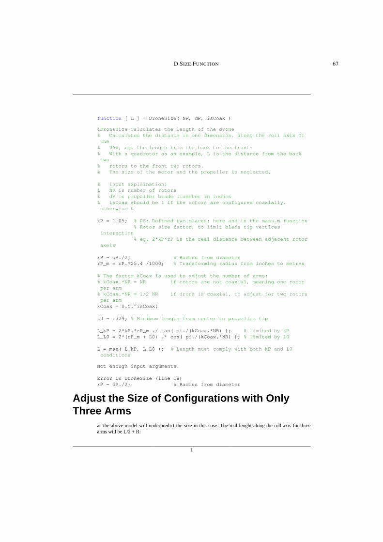
1
function [ L ] = DroneSize( NR, dP, isCoax )
%DroneSize Calculates the length of the drone% Calculates the distance in one dimension, along the roll axis of the% UAV, eg. the length from the back to the front.% With a quadrotor as an example, L is the distance from the back two% rotors to the front two rotors.% The size of the motor and the propeller is neglected.
% Input explaination:% NR is number of rotors% dP is propeller blade diameter in inches% isCoax should be 1 if the rotors are configured coaxially, otherwise 0
kP = 1.05; % PS: Defined two places; here and in the mass.m function % Rotor size factor, to limit blade tip vertices interaction % eg. 2*kP*rP is the real distance between adjacent rotor axels
rP = dP./2; % Radius from diameterrP_m = rP.*25.4 /1000; % Transforming radius from inches to metres
% The factor kCoax is used to adjust the number of arms:% kCoax.*NR = NR if rotors are not coaxial, meaning one rotor per arm% kCoax.*NR = 1/2 NR if drone is coaxial, to adjust for two rotors per armkCoax = 0.5.^isCoax;
L0 = .329; % Minimum length from center to propeller tip
L_kP = 2*kP.*rP_m ./ tan( pi./(kCoax.*NR) ); % limited by kPL_L0 = 2*(rP_m + L0) .* cos( pi./(kCoax.*NR) ); % limited by L0
L = max( L_kP, L_L0 ); % Length must comply with both kP and L0 conditions
Not enough input arguments.
Error in DroneSize (line 18)rP = dP./2; % Radius from diameter
Adjust the Size of Configurations with OnlyThree Arms
as the above model will underpredict the size in this case. The real lenght along the roll axis for threearms will be L/2 + R:
D SIZE FUNCTION 67

2
% Need R:% The horizontal distance from the center of the drone to the rotorR = kP*rP_m ./ sin( pi./(kCoax.*NR) ); % Geometric relationship
% Adjusting formula based on how many inputs NR and isCoax hasif length(NR) == 1 && length(isCoax) == 1 if NR*kCoax == 3 % If number of arms = 3 L = L/2 + R; endelseif length(NR) == 1 for i = 1:length(L); if NR*kCoax(i) == 3 L(i) = L(i)/2 + R(i); end endelseif length(isCoax) == 1 for i = 1:length(L); if NR(i)*kCoax == 3 L(i) = L(i)/2 + R(i); end endelse for i = 1:length(L); if NR(i)*kCoax(i) == 3 L(i) = L(i)/2 + R(i); end endend
end
Published with MATLAB® R2016a
68 D SIZE FUNCTION


