
University of Birmingham
Optimisation of stirred vessel geometry for thedrawdown and incorporation of floating solids toprepare concentrated slurriesWood, Thomas; Simmons, Mark J. H.; Stitt, Hugh E.
DOI:10.1016/j.cherd.2018.03.002
License:Creative Commons: Attribution (CC BY)
Document VersionPublisher's PDF, also known as Version of record
Citation for published version (Harvard):Wood, T, Simmons, MJH & Stitt, HE 2018, 'Optimisation of stirred vessel geometry for the drawdown andincorporation of floating solids to prepare concentrated slurries', Chemical Engineering Research and Design,vol. 133, pp. 70-78. https://doi.org/10.1016/j.cherd.2018.03.002
Link to publication on Research at Birmingham portal
Publisher Rights Statement:Published in Chemical Engineering Research and Design on 09/03/2018
DOI: 10.1016/j.cherd.2018.03.002
General rightsUnless a licence is specified above, all rights (including copyright and moral rights) in this document are retained by the authors and/or thecopyright holders. The express permission of the copyright holder must be obtained for any use of this material other than for purposespermitted by law.
•Users may freely distribute the URL that is used to identify this publication.•Users may download and/or print one copy of the publication from the University of Birmingham research portal for the purpose of privatestudy or non-commercial research.•User may use extracts from the document in line with the concept of ‘fair dealing’ under the Copyright, Designs and Patents Act 1988 (?)•Users may not further distribute the material nor use it for the purposes of commercial gain.
Where a licence is displayed above, please note the terms and conditions of the licence govern your use of this document.
When citing, please reference the published version.
Take down policyWhile the University of Birmingham exercises care and attention in making items available there are rare occasions when an item has beenuploaded in error or has been deemed to be commercially or otherwise sensitive.
If you believe that this is the case for this document, please contact [email protected] providing details and we will remove access tothe work immediately and investigate.
Download date: 11. May. 2020

Chemical Engineering Research and Design 1 3 3 ( 2 0 1 8 ) 70–78
Contents lists available at ScienceDirect
Chemical Engineering Research and Design
journa l h om epage: www.elsev ier .com/ locate /cherd
Optimisation of stirred vessel geometry for thedrawdown and incorporation of floating solids toprepare concentrated slurries
Thomas Wooda,b, Mark J.H. Simmonsb, E. Hugh Stitta,∗
a Johnson Matthey Technology Centre, P.O. Box 1, Belasis Avenue, Billingham, TS23 1LB, UKb School of Chemical Engineering, University of Birmingham, Birmingham B15 2TT, UK
a r t i c l e i n f o
Article history:
Received 30 October 2017
Received in revised form 28
February 2018
Accepted 2 March 2018
Available online 9 March 2018
Keywords:
Suspensions
Drawdown
Floating solids
Stirred tank
Optimisation
a b s t r a c t
This paper reports on a Design of Experiments (DoE) approach to optimise the geometric
configuration for effective drawdown and incorporation of floating solids to prepare high
solid content slurries. The impeller speed and power draw required to ensure all dry pow-
der is incorporated within four seconds of addition to the vessel free surface, NJI and PJI, were
used as metrics to determine incorporation performance. Mixed flow pitched blade turbines
at D/T = 0.5 were used. The main parameters considered were the impeller pumping direc-
tion (up versus down), impeller submergence, eccentricity, and angle of tilt. DoE was used
to examine both the independent effects of the main parameters and their interactions.
Pumping mode was found to be the most significant parameter, with down-pumping
impellers generally providing the best drawdown and incorporation performance. This is
related to the strong interaction between pumping mode and all other parameters, where
adding tilt or eccentricity reduced drawdown performance for up-pumping impellers, yet
caused improvement in the case of down-pumping impellers.
The optimal geometry from the DoE was found using a down-pumping PBT, 10◦ tilt, 10%
of the vessel diameter eccentricity and placed at an initial submergence of half the liquid
height. This geometry is shown to reduce the time required to prepare a 50 wt% slurry by two
thirds compared to a generic Rushton turbine design, emphasising the benefits of rational
impeller and vessel design.
© 2018 The Authors. Published by Elsevier B.V. on behalf of Institution of Chemical
Engineers. This is an open access article under the CC BY license (http://creativecommons.
org/licenses/by/4.0/).
tling force which prevents the particles from sinking, even if they have
1. Introduction
Drawdown of floating solids in stirred vessels is a common process
operation for many industries to incorporate solids for dissolution,
reaction, or suspension and slurry preparation. Examples of draw-
down processes can be found throughout the polymer, paint, food, and
catalyst industries, amongst others. The specific requirement of the
drawdown duty is highly dependent upon the solid and liquid phase
composition. For example the drawdown, incorporation and suspen-
sion of small particle ceramic materials in concentrated slurries for
paints or catalyst washcoats will behave differently to the drawdown of
∗ Corresponding author.E-mail address: [email protected] (E.H. Stitt).
https://doi.org/10.1016/j.cherd.2018.03.0020263-8762/© 2018 The Authors. Published by Elsevier B.V. on behalf ofunder the CC BY license (http://creativecommons.org/licenses/by/4.0/).
low solid concentration buoyant particles for dissolution, mass trans-
fer, ion exchange, or reaction processes (Siddiqui, 1993).
Solid particles may float for a variety of reasons (Waghmare et al.,
2011). Firstly, if the density of the solid particles is lower than the fluid
they will float if not agitated. Using agitation to draw these particles
down into the fluid forms a dynamic equilibrium where, if agitation
ceases, they will return to rest at the top surface. Secondly, if the interfa-
cial tension between the solid and liquid is sufficiently high, this causes
a force at the surface with a larger magnitude than the gravitational set-
a higher density than the fluid (Rouquerol et al., 2013). Thirdly, particles
Institution of Chemical Engineers. This is an open access article

Chemical Engineering Research and Design 1 3 3 ( 2 0 1 8 ) 70–78 71
Nomenclature
Impeller tilt angle (◦)C Impeller off-bottom clearance (m)D Impeller diameter (m)E Impeller eccentricity (m)H Liquid height (m)H0 Initial liquid height (m)N Impeller speed (RPM)P Impeller power draw (W)S Impeller submergence (m)S0 Initial impeller submergence (m)T Vessel diameter (m)
c
f
a
p
t
t
s
r
c
h
a
w
fl
t
t
h
s
f
p
K
i
t
T
i
s
s
t
v
a
d
t
p
r
d
c
m
i
a
m
fl
w
i
2
T
w
T
l
t
an agglomerate at the surface, with liquid bridges between particles,
orming a large semi-wet mass with occluded air. The presence of this
ir gives this agglomerate a lower envelope density than the original
articles and so it may float until it is broken up. An important dis-
inction between the three cases is that whilst the first is reversible,
he latter two are not. Once the particles are either pulled through the
urface and/or fully wetted they will become non-buoyant and will not
eturn to the surface once agitation is stopped; rather they will most
ommonly sediment.
Each of the three phenomenon described above do not necessarily
appen in isolation. For example, in the case of porous ceramic powders
ll can potentially occur. Initially, the pores of the particles are filled
ith air and so the envelope density will be low. As the pores fill with
uid (a process that depends on the interfacial tension between the
wo phases) the envelope density will increase until it rises to above
hat of the fluid. However, the particles may also agglomerate as they
it the liquid surface, leading to a very complex force balance on the
ystem.
Due to the complexity of the problem, previous studies have largely
ocused on simple systems. For example, large, low density buoyant
articles have been used to isolate the phenomena (Hemrajani, 1988;
hazam and Kresta, 2008, 2009; Özcan-Taskin, 2006). The effect of var-
ous geometric parameters on the impeller speed (NJD) and power (PJD)
o just drawdown the solid from the liquid surface have been explored.
he just drawdown criterion, NJD, first proposed by Joosten et al. (1977),
s the impeller rotation rate at which no solid spends more than four
econds at the free surface. This is analogous to the well-known “just
uspended” criterion by Zwietering (1958) which is the impeller rota-
ion rate at which no particle spends more than 2 s in contact with the
essel bottom.
Whilst NJD is a useful parameter to study the effect of geometry
t a given solids concentration, it relies upon the reversibility of the
rawdown process. This is of course only true for the first of the above
hree conditions given by Waghmare et al. (2011). In the context of the
resent study, all three apply and hence the drawdown process is not
eversible. Therefore a similar condition, the “just incorporation” con-
ition, was proposed by Wood et al. (2018) for non-buoyant solids that
an be incorporated into slurries. This measurement is very similar,
easuring the impeller speed required, NJI, to ensure all powder added
s drawn down and incorporated within four seconds of addition, where
fixed amount of solid is added at a time at a fixed frequency, allowing
easurement of drawdown to be carried out for concentrated systems.
Amongst previous studies there is a general consensus that mixed
ow pitched blade turbine (PBT) impellers give the best performance,
ith significant power and speed savings compared to radial flow
mpellers (Joosten et al., 1977; Khazam and Kresta, 2009; Özcan-Taskin,
006; Özcan-Taskin and McGrath, 2001; Özcan-Taskin and Wei, 2003;
akahashi and Sasaki, 1999; Wood et al., 2018). The majority of these
orks have focussed on down-pumping impellers, although Özcan-
askin and Wei (2003) demonstrated that up-pumping impellers ran at
ower NJD and PJD than down-pumping impellers when placed close to
he surface. Given the consistent conclusions within previous litera-
ture, only pitched blade turbines are considered in this study; both up-
and down-pumping.
The effect of submergence on drawdown performance has been
considered by several researchers, with conflicting conclusions. Özcan-
Taskin and McGrath (2001) reported good performance at high impeller
submergences, specifically for radial flow impellers and downward
pumping PBTs. Khazam and Kresta (2009) showed that the cloud depth
within the vessel improved with a higher submergence at the cost of
increasing both the impeller speed and power required for drawdown
for a novel geometry using a down-pumping impeller, regardless of
baffle configuration. Özcan-Taskin and Wei (2003) showed that whilst
drawdown performance, in terms of NJD, improved as the submergence
was increased for down-pumping impellers, the opposite was true for
up-pumping impellers. Khazam and Kresta (2009) made a similar obser-
vation that up-pumping impellers are much more sensitive to the effect
of submergence than down-pumping impellers.
Previous studies focussing on low solid contents and solids that
cannot be incorporated demonstrated an improvement in drawdown
performance when using baffles. Various baffle geometries have been
studied and generally show improved performance over the unbaf-
fled case; this includes the use of one, two and four baffles that can
either be full vessel height or surface only baffles (Hemrajani, 1988;
Karcz and Mackiewicz, 2009; Khazam and Kresta, 2009; Özcan-Taskin
and McGrath, 2001; Siddiqui, 1993). However, baffles have been shown
to inhibit the drawdown and incorporation of incorporable solids (i.e.
those that, once wetted, incorporate to form a slurry rather than return-
ing to the surface) during slurry preparation, especially as the slurry
solid content is increased above 10% (Wood et al., 2018). Therefore, it is
important to examine non-standard geometries to reduce quasi-solid
body rotation and improve mixing performance within the vessel. The
use of eccentric impellers is a common technique to improve mixing
in unbaffled systems, shown to give equally efficient mixing as a baf-
fled vessel (Hall et al., 2004, 2005). Waghmare et al. (2011) demonstrated
some promise in the use of a tilted impeller for drawdown, a practice
that has been shown to potentially improve mixing performance over
unbaffled systems (Chung, 2008).
There are a limited number of studies that consider the effect of
increasing the concentration of the solid phase on the mixing system.
Xie et al. (2007) studied the deagglomeration of fumed silica agglom-
erates of up to 10 wt% and found that the drawdown requirement
(in terms of drawdown time) increased exponentially with increas-
ing solid concentration for all impellers studied. Khazam and Kresta
(2009) examined a system containing expanded polystyrene up to a
maximum concentration of 10% by volume and found the drawdown
requirements (in terms of NJD) significantly increased with increas-
ing solid concentration. Özcan-Taskın (2012) studied the incorporation
of nanoscale clusters into a suspension using a proprietary design of
mixer and found that the drawdown requirement (in terms of incorpo-
ration time) increased with increasing solid concentrations, especially
above solid concentrations of 10 wt% up to a maximum of 20 wt%.
The effect of D/T is significant on drawdown performance and
has been studied by multiple authors (Joosten et al., 1977; Özcan-
Taskin and McGrath, 2001; Özcan-Taskin and Wei, 2003; Takahashi
and Sasaki, 1999), again with varying conclusions. Generally larger
impellers require lower speeds to achieve the same drawdown perfor-
mance at the cost of increased power draw. However, Wood et al. (2018)
demonstrated that a larger diameter PBT (D/T = 0.5) provided much bet-
ter incorporation at higher solids content (>40%) and this outweighed
the lower power of smaller D/T at low solids content (<20%) in overall
process terms.
Design of Experiments (DoE) is a useful tool to ensure the maximum
information is obtained from a process using a minimised set of exper-
imental conditions. In a factorial DoE approach, process parameters
are varied systematically within an orthogonal design space in order
to assess efficiently the effect of each considered parameter on an out-
put, or response variable. This approach also allows the consideration
of interactions between the process variables while minimising alias-
ing between them, allowing optimisation of that response for a given
system (Montgomery, 2012).

72 Chemical Engineering Research and Design 1 3 3 ( 2 0 1 8 ) 70–78
Fig. 1 – Vessel schematic.
Table 1 – Design of Experiments: variable high, centrepoint, and low values.
Variable High Centre point LowPumping mode Up – DownEccentricity 0.2 T 0.1 T 0Tilt (◦) 20 10 0Submergence 0.3 T 0.5 T 0.7 T
This study considers the effect of increasing and high solid concen-
trations on the geometric parameters for mixing in a 5 dm3 cylindrical
stirred vessel. This allows optimised vessel designs to be found for
industrially relevant high solid content systems with incorporable
solids. This study also considers the interactions between different
geometric parameters rather than considering each in isolation; some-
thing not previously examined. Non-standard parameters, such as
impeller tilt and eccentricity, are also considered as a method of reduc-
ing quasi-solid body rotation, while avoiding the use of baffles, which
have previously been shown to inhibit the drawdown of incorporable
solids above approximately 10 wt.% solids (Wood et al., 2018).
2. Experimental
All experiments were carried out in a flat bottomed cylindrical5 dm3 vessel with diameter, T = 0.17 m and initial liquid height,H0 = T. The geometric parameters considered were impellerpumping mode (up- versus down-pumping PBTs), impellereccentricity, impeller tilt, and impeller submergence, shownin Fig. 1. No baffles were used in the vessel. The impellers stud-ied had a diameter, D = 0.085 m (D/T = 0.5). This diameter wasselected based on previous studies indicating that this wouldoutperform smaller impellers in terms of required impellerspeed and power at higher solid contents (Wood et al., 2018).
The vessel was filled to an initial height, H0/T = 1, with3.86 dm3 of liquid. An equal mass of solid was pre-weighedinto 50 aliquots of 77 g using a KTron KT20 loss in weight pow-der feeder set to deliver a fixed mass. Each aliquot was pouredin one motion to the centre of the vessel to remove disturbanceeffects due to addition location or rate. An aliquot was addedevery two minutes. The impeller speed was adjusted upwardsas required to ensure that the “just incorporated” conditionwas maintained throughout the experiment.
The total mass of powder added was 3.85 kg, giving afinal slurry concentration (X) of 50 wt.%. A porous �-alumina,
Sasol Puralox SCFa-140, was used as the dispersible solid.This alumina is a porous ceramic, with a poured bulk densityof approximately 560 kg m−3 and D50 of 30 �m, that initiallyfloats. Once incorporated however, the pores fill with fluid andthe particles sediment if not agitated. Powder was added in 50aliquots to allow the effect of increasing solid concentrationto be seen on drawdown performance. It also ensured eachaliquot was sufficiently large to completely cover the liquidsurface when at rest.
An aqueous acetic acid solution, initially 6 wt% acetic acidand pH 3, was used as the liquid. This was done in order tomaintain a low viscosity, Newtonian liquid throughout theexperiment by ensuring that pH remained well below the iso-electric point of the alumina slurry. The pH of a final 50 wt%slurry was in the range 4.8–5, whereas the isoelectric point forthis powder is in the range 7.7–7.9 (Adegbite, 2010). The ves-sel was double walled with a cooling water flow through theouter jacket. The cooling water was kept at 5 ◦C. This was usedto reduce the effect of slurry temperature on viscosity.
The incorporation performance is defined as the impellerspeed and power required to ensure the Just Incorporationcondition where no fresh powder spent longer than four sec-onds at the vessel surface, see Wood et al. (2018). Thesemeasures are termed NJI and PJI respectively and are simi-lar to the Just Drawdown condition used in reported studiesby other workers. However, the conditions are distinct as justdrawdown is a steady state, reversible condition, whereas justincorporation is not.
An initial H/T = 1 was used in all experiments. As solid wasadded to the vessel the liquid level increased to give a finalH/T = 1.2, meaning that the initial and final submergence ofthe impeller are different. This increase in liquid level andsubmergence does have a detrimental effect on the drawdownand incorporation of powder from the surface with all othergeometric parameters remaining constant (Wood et al., 2018).However, this effect is considerably smaller than the effect ofthe increasing solid content.
The impeller shaft torque (�) was measured using a cali-brated Binsfield TorqueTrak 10k wireless strain gauge attachedto the shaft. The impeller power draw was then calculatedfrom the torque as:
P = 2�N� (1)
The measured torque, and so impeller power draw wasfound to fluctuate by ±5% of the reading value. All valuesquoted are the mean value recorded over time at a samplingfrequency of 10 Hz.
A full factorial design of experiments (DoE) with centrepoints approach was used to design an experimental matrixto maximise the information captured regarding the effectof individual variables and the interactions between differentvariables. The high, centre point, and low values for each ofthe variables considered are shown in Table 1.
The design, with four variables and two centre points (one
for each pumping mode) gives rise to 18 trials, as shown inTable 2. Each experiment was repeated three times. Measure-
Chemical Engineering Research and Design 1 3 3 ( 2 0 1 8 ) 70–78 73
Table 2 – List of trials.
Run order Pumping mode Eccentricity Tilt Submergence
1 Down 0.2 20 0.32 Up 0.2 20 0.73 Down 0.2 0 0.74 Down 0.2 0 0.35 Down 0 0 0.36 Down 0 20 0.37 Up 0 0 0.78 Down 0 20 0.79 Up 0 0 0.310 Up 0 20 0.711 Up 0 20 0.312 Down 0.1 10 0.513 Down 0 0 0.714 Down 0.2 20 0.715 Up 0.2 0 0.716 Up 0.2 0 0.317 Up 0.1 10 0.5
mvovdTab
npatsoa
gavotrnto
3
Ffdlcstebjodaaf
Fig. 2 – (a) NJI evolution with increasing solid content forfirst four runs; (b) PJI evolution with increasing solidcontent for first four runs.
Table 3 – NJI results for 30 wt% slurries and linear modelparameters for each trial.
Run order NJI at 30 wt% Gradient Intercept
1 240 3.0 1632 450 2.6 3453 290 1.3 2644 320 2.5 2785 300 2.4 2756 250 2.1 2227 305 0.8 2818 260 1.1 2419 295 1.9 26710 440 0.6 41811 330 2.3 29512 250 2.1 20313 320 1.5 29414 265 1.8 22615 335 2.9 27116 320 1.3 28917 350 1.2 31418 360 1.3 321
18 Up 0.2 20 0.3
ents were found to be repeatable to ±5 RPM. The averagealues of the three runs are reported herein. For trials outsidef the DoE design space described in Table 2 each of the otherariables were kept constant, at a standard value. The stan-ards used in these cases were taken as the “low” values fromable 1 for all parameters. These further non-orthogonal tri-ls were added following the orthogonal DoE to probe furtherehaviour of a single parameter at a time.
Following this initial scoping factorial design, each of theumeric factors were further probed with additional dataoints both inside the initial design space, and outside whereppropriate. This was done to find turning points in behaviouro find optimal configurations. This involved measuring atubmergences between 0.1 T–0.8 T in 0.1 T increments, at tiltsf 5◦ and 15◦, and at eccentricities of 0.5 T, and 0.15 T as wells the initial scoping set points.
In order to validate the effect of optimising the vesseleometry, a trial was carried out. During this trial powder wasdded to the vessel as quickly as possible (as soon as the pre-ious aliquot had been drawn down) at a fixed impeller speedf 450 RPM (the maximum speed required to maintain NJI forhe optimum configuration up to 50 wt%). The time and energyequired to prepare a 50 wt% slurry was measured in this man-er for both the optimal geometry and a six bladed Rushtonurbine with D/T = 0.5, S0/T = 0.7, with no baffles, eccentricityr tilt.
. Results and discussion
ig. 2 shows the measured of NJI and PJI data respectivelyor the first four trials in the experimental matrix. Betterrawdown and incorporation performance is characterised by
ower NJI and lower PJI at a given solids content. At low solidontents (<30 wt%) NJI increases approximately linearly witholid content and so can be modelled as a straight line withhe intercept and gradient values shown in Table 3. Woodt al. (2018) observed that there is a significant increase inoth impeller speed and power draw required to maintain
ust incorporation as the solid content increases. It was alsobserved that, for the most part, impeller selection rankingoes not change with increasing solids content; what is goodt low solids remains good at high solids and vice versa. The
bove sample of results indicates that the same is largely trueor geometrical designs. Thus, poor performing geometriesperform poorly at low and high solids content. The differencein power draw between the best and worst does become lesssignificant at highest solids, as the effect of the high viscositydominates over geometry considerations. The impact of thespecific geometric design parameters will be discussed in thecontext of the statistical analysis of the data.

74 Chemical Engineering Research and Design 1 3 3 ( 2 0 1 8 ) 70–78
pell
Fig. 3 – Main Effects Plot at 30 wt% for im3.1. Main variable effects
When using a Design of Experiments approach, the simplestmethod of looking at the effect of each variable is via the MainEffects plot shown in Fig. 3. This takes the mean value of allmeasurements for a variable at each set point. For examplethe Main Effect value for ‘down’ for pumping mode wouldbe the average of runs 1, 3–6, 8, 12–14. Fig. 3 uses the meanvalue of NJI for each variable under each condition studiedand can be used to examine high level trends from each ofthe variables considered. This approach allows considerationof both categoric and numerical variables. The importance ofeach primary variable is reflected simply by the ranges of theoutput variable responses: pumping mode is the most impor-tant, tilt and eccentricity have similar (non-monotonic) butminor effects while submergence seems to become impor-tant at higher values (where the impeller is in the lower halfof the vessel). Simply considering the main effects suggeststhat using a down pumping PBT with 10◦ tilt, E/T = 0.1, and alow submergence will give the best drawdown performance, asthis is the set of variable conditions which each give the lowestvalue of NJI and therefore best incorporation performance.
Fig. 4 shows the main effects for the impeller power draw atthe just incorporated condition. Pumping mode is significant,as it was for NJI. Impeller tilt and eccentricity both increasethe required power because both serve to increase radial andaxial flow, reducing tangential flows thus giving increasedwhole vessel mixing. Submergence shows a similar trend forpower to that for NJI, becoming significant for higher values.In similar fashion to the Main Effects Plot for impeller speed, adown-pumping impeller with a small tilt and eccentricity witha submergence above the bottom half of the vessel gives thebest drawdown performance, minimizing both power drawand impeller speed.
3.2. Variable interactions
The above discussion and results presentation considers onlythe uni-variate impact of each design parameter. Stirred vessel
design is however a multi-variate problem and it is there-fore important to assess the inter-dependency of the primaryer speed at just incorporation condition.
parameters. Fig. 5 shows the interaction plot which presentsa more detailed breakdown of the Main Effects Plot, separat-ing the design parameters to assess the interactions betweenthem. Each point on the interaction plot represents the meanvalue of all runs with both variables considered, held at a spe-cific set point. To aid interpretation of these plots, converginglines in Fig. 5 indicate the presence of interactions betweenvariables whereas parallel lines suggest those two variablesare independent.
There is a strong interaction between pumping mode andevery other variable, as seen in the first column. This meansthere is a significantly different response when changingtilt, eccentricity, or submergence depending on whether theimpeller is in an up- or down-pumping mode. For each ofthese interactions the best performance for the up-pumpingimpeller is the low value for each variable, whereas for thedown-pumping impeller it is the centre point of the high value.Each of these interactions is considered in more detail below.
There is also a slight interaction between impeller tiltand submergence, with tilting the impeller proving to bedetrimental to drawdown performance at higher impeller sub-mergences. This matches with experimental observation thatat high submergence and high tilt the impeller shaft passesthrough the liquid surface close to the vessel wall resulting ina very narrow gap where dry or semi-wetted powder agglom-erates would adhere to the wall and shaft, creating a staticsite for further agglomeration which could not be easily drawndown and incorporated.
There is no interaction between eccentricity and impellertilt. This is probably because they both achieve similar effectson the flow pattern; reducing quasi-solid body rotation andincreasing axial and radial flows in the vessel and increasingthe impeller power delivery.
3.3. Complex variable effects
Some of the main effects and interactions present complexand non-linear trends that require further investigation, suchas the interaction between pumping mode and tilt and the
impact of submergence. These are explored in more detailbelow.
Chemical Engineering Research and Design 1 3 3 ( 2 0 1 8 ) 70–78 75
Fig. 4 – Main Effects Plot at 30 wt% for impeller power at just incorporation condition.
pelle
bsmiaalTm
opidu
Fig. 5 – Interaction Plot at 30 wt% for im
Fig. 6 shows a more detailed view of the interactionetween pumping mode and impeller tilt, where each mea-urement is represented by a single point. It also includes extraeasurements at tilts of 5◦ and 15◦ to further probe the linear-
ty of the system response to impeller tilt. The spread of pointst 0◦ and 20◦ show the presence of an effect from other vari-bles. It is important to note that this spread is significantlyarger for the up-pumping impeller than for down-pumping.his indicates that when pumping upwards the system isuch more sensitive to the effect of the variables changing.There is a different response to impeller tilt depending
n pumping mode, with a small improvement in drawdownerformance generally seen with tilting a down-pumping
mpeller. Conversely, there is generally a decrease in draw-
own performance with increasing impeller tilt for anp-pumping impeller.r speed at just incorporation condition.
In Fig. 7, the effect of eccentricity is minimal regardlessof pumping direction. Again, each individual point repre-sents a single measurement with extra trials on top ofthe DoE at E = 0.05 T and E = 0.15 T to probe the linearity ofthe system response to eccentricity. There is evidence of aslight negative correlation between tilt and NJI for the down-pumping impeller, suggesting that eccentricity can marginallyimprove drawdown performance. This is not the case forthe up-pumping impeller where there is no obvious effect ofeccentricity.
The up-pumping impeller again shows a significantlylarger spread of values than the down-pumping impeller,showing a greater dependency on geometry interactions thanthe down-pumping impeller for effective drawdown to occur.
The minimum impeller speed required for the down-pumpingimpeller is seen at a slight eccentricity of 0.1 T. However, the
76 Chemical Engineering Research and Design 1 3 3 ( 2 0 1 8 ) 70–78
Fig. 6 – Effect of interaction between impeller tilt andpumping mode on NJI at 30 wt% solid content.
Fig. 7 – Effect of interaction between impeller eccentricity
Fig. 8 – (a) Change in NJI with increasing solid content andvarying impeller initial submersion (b) Difference betweenhighest and lowest required NJI across all submergencesmeasured.
and pumping mode on NJI.
minimum for the up-pumping impeller is found at zero eccen-tricity.
Fig. 8a shows the three-way interaction between submer-gence, solid content and pumping mode. Each set of pointsis a single experiment, where solid content was increasedfor a constant geometry, using “low” values for eccentricityand tilt for three different submergences for each impeller.Again; there is a different response to submergence depend-ing on pumping mode. For the down-pumping impeller thebest performance was at an initial submergence of S0/T = 0.5whereas, for the up-pumping impeller best performance wasas close to the surface as possible at S0/T = 0.3. This differ-ence is explained by visual observations when conductingthe experiments as the down-pumping impeller entrainedair from the surface straight to the impeller, reducing theeffectiveness of the impeller whereas the flow pattern in up-pumping mode prevented this. Both impellers gave their worstdrawdown performance when in the bottom half of the vesselwith an S0/T = 0.7.
At the lowest solid contents studied, the up-pumpingimpeller was more sensitive to impeller depth, with a largerdifference between the impeller speeds required at the bestand worst performing depths, as shown in Fig. 8b, whichshows the difference between the best and worst performingsubmergence in Fig. 8a. This is a consistent with the obser-
vations of Khazam and Kresta (2008). However, as the solidcontent increases this difference between pumping modebecomes less marked, a new result since this phenomenonhas not previously been studied at higher solid contents.
Fig. 9a shows the effect of submergence on impeller speedrequired for drawdown for an up-pumping impeller with notilt or eccentricity. As seen in other studies on low solid con-tents; increasing the impeller submergence above ∼0.6 T hasa negative impact on drawdown and incorporation perfor-mance. However, in contrast to many of these other works,performance does not continue to increase indefinitely as theimpeller is brought closer to the surface. At submergencesless than 0.4 T there was significant air entrainment, causingsemi-permanent bubbles to form at the liquid surface. Thesebubbles provided surface area for dry or semi wet solid to bindto, increasing buoyancy force and preventing full incorpora-tion into the slurry. Fig. 9b shows the PJI values as a functionof S0/T and indicates that the power draw fall off significantlyat S0 below 0.3 T; despite an increasing NJI. A gassed systemwould draw significantly less power than an un-gassed system(Middleton, 1992). This fall off in power draw thus confirmsthat surface aeration is significant and the probable cause ofthe loss of incorporation performance. Although good draw-down performance was seen for a submergence of 0.3 T, oncethe vessel was drained a significant amount of sediment wasfound on the base of the vessel. This was not true for greaterimpeller submergences, suggesting that for submergences of0.3 T and below, the impeller is too far from the base of the
vessel to provide sufficient vessel turnover to ensure completesuspension at the Just Incorporation condition.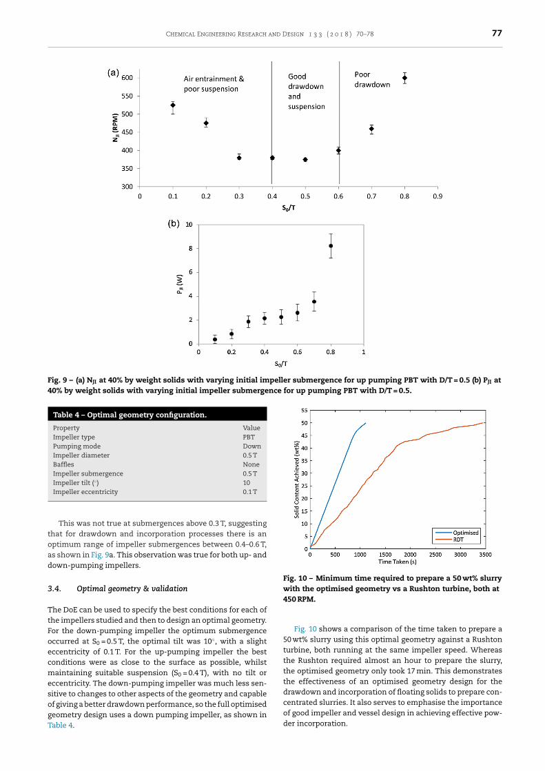
Chemical Engineering Research and Design 1 3 3 ( 2 0 1 8 ) 70–78 77
Fig. 9 – (a) NJI at 40% by weight solids with varying initial impeller submergence for up pumping PBT with D/T = 0.5 (b) PJI at40% by weight solids with varying initial impeller submergence for up pumping PBT with D/T = 0.5.
Table 4 – Optimal geometry configuration.
Property ValueImpeller type PBTPumping mode DownImpeller diameter 0.5 TBaffles NoneImpeller submergence 0.5 TImpeller tilt (◦) 10Impeller eccentricity 0.1 T
toad
3
TtFoecmesogT
Fig. 10 – Minimum time required to prepare a 50 wt% slurrywith the optimised geometry vs a Rushton turbine, both at450 RPM.
This was not true at submergences above 0.3 T, suggestinghat for drawdown and incorporation processes there is anptimum range of impeller submergences between 0.4–0.6 T,s shown in Fig. 9a. This observation was true for both up- andown-pumping impellers.
.4. Optimal geometry & validation
he DoE can be used to specify the best conditions for each ofhe impellers studied and then to design an optimal geometry.or the down-pumping impeller the optimum submergenceccurred at S0 = 0.5 T, the optimal tilt was 10◦, with a slightccentricity of 0.1 T. For the up-pumping impeller the bestonditions were as close to the surface as possible, whilstaintaining suitable suspension (S0 = 0.4 T), with no tilt or
ccentricity. The down-pumping impeller was much less sen-itive to changes to other aspects of the geometry and capablef giving a better drawdown performance, so the full optimisedeometry design uses a down pumping impeller, as shown in
able 4.Fig. 10 shows a comparison of the time taken to prepare a50 wt% slurry using this optimal geometry against a Rushtonturbine, both running at the same impeller speed. Whereasthe Rushton required almost an hour to prepare the slurry,the optimised geometry only took 17 min. This demonstratesthe effectiveness of an optimised geometry design for thedrawdown and incorporation of floating solids to prepare con-centrated slurries. It also serves to emphasise the importanceof good impeller and vessel design in achieving effective pow-
der incorporation.
78 Chemical Engineering Research and Design 1 3 3 ( 2 0 1 8 ) 70–78
agitators. Chem. Eng. Sci. 8, 244–253,
4. Conclusions
This work uses a design of experiments approach to fullyoptimise a geometry for the drawdown and incorporation offloating solids to prepare high solid content suspensions. Theuse of a full factorial orthogonal DoE enables an analysis of theeffects of key geometric variables and their interactions. Thevariables specifically focussed on are impeller pumping mode,tilt, eccentricity, and submergence within the mixing vessel.
The most significant variable is impeller pumping modewith down-pumping impellers generally out performing up-pumping impellers in terms of drawdown performance.Down-pumping impellers give the best possible performancein terms of the smallest possible NJI required under optimalconfiguration, but also in terms of sensitivity to interactionswith other variables. The up-pumping impeller showed sig-nificant decreases in performance if moved eccentric, tiltedor at higher initial submergences whereas the down-pumpingimpeller showed improvements with tilt and eccentricity.
The best performing set of conditions involved using adown-pumping PBT with no baffles and D/T = 0.5 at an initialsubmergence halfway down the vessel (S0/T = 0.5; H0/T = 1), a10◦ tilt and eccentricity of 0.1 T. The best set of conditions forusing an up-pumping impeller were as close to the surface aspossible (S0/T = 0.4), no impeller tilt, or eccentricity. However,there was a significant amount of sedimentation at the low-est submergences for both up- and down-pumping impellerstherefore it is not recommended to operate at an S0/T < 0.4 tomaintain effective drawdown, incorporation and suspension.
Comparison of the optimised geometry against a genericmixing geometry employing a Rushton turbine showed a dra-matic reduction in processing time of one third to prepare a50 wt% slurry by the optimised geometry. This demonstratesthe effectiveness of simple geometry optimisation for this pro-cess.
Acknowledgements
Thomas Wood is funded by the EPSRC Centre for DoctoralTraining in Formulation Engineering at the University of Birm-ingham (EP/L015153/1) and Johnson Matthey.
References
Adegbite, S., 2010. Coating of Catalyst Supports: Links BetweenSlurry Characteristics, Coating Process and Final CoatingQuality (PhD). University of Birmingham, Birmingham.
Chung, K.H.K., 2008. Mixing in High Throughput ExperimentationReactors (PhD). University of Birmingham.
Hall, J.F., Barigou, M., Simmons, M.J.H., Stitt, E.H., 2004. Mixing inunbaffled high-throughput experimentation reactors. Ind.Eng. Chem. Res. 43, 4149–4158,http://dx.doi.org/10.1021/ie049872q.
Hall, J.R., Barigou, M., Simmons, M.J.H., Stitt, E.H., 2005. A PIV
study of hydrodynamics in gas-liquid high throughputexperimentation (HTE) reactors with eccentric impellerconfigurations. Chem. Eng. Sci. 60, 6403–6413,http://dx.doi.org/10.1016/j.ces.2005.03.044.
Hemrajani, R.R., 1988. Suspending floating solids in stirred tanks:mixer design, scale-up and optimization. Presented at theProceedings of the 6th European Conference on Mixing, Pavia,Italy, pp. 259–265.
Joosten, G.E.H., Schilder, J.G.M., Broere, A.M., 1977. Suspension offloating solids in stirred vessels. Trans. Inst. Chem. Eng. 55,220–222.
Karcz, J., Mackiewicz, B., 2009. Effects of vessel baffling on thedrawdown of floating solids. Chem. Pap. 63, 164–171,http://dx.doi.org/10.2478/s11696-009-0011-0.
Khazam, O., Kresta, S.M., 2009. A novel geometry for solidsdrawdown in stirred tanks. Chem. Eng. Res. Des. 87, 280–290,http://dx.doi.org/10.1016/j.cherd.2008.09.013.
Khazam, O., Kresta, S.M., 2008. Mechanisms of solids drawdownin stirred tanks. Can. J. Chem. Eng. 86, 622–634,http://dx.doi.org/10.1002/cjce.20077.
Middleton, J.C., 1992. Gas liquid dispersion and mixing. In:Harnby, N., Edwards, M.F., Nienow, A.W. (Eds.), Mixing in theProcess Industries. Butterworth-Heinemann, pp. 322–363.
Montgomery, D.C., 2012. Design and Analysis of Experiments, 8thedition. John Wiley & Sons, Hoboken, NJ.
Özcan-Taskin, G., 2006. Effect of scale on the draw down offloating solids. Chem. Eng. Sci. 61, 2871–2879,http://dx.doi.org/10.1016/j.ces.2005.10.061.
Özcan-Taskın, G.N., 2012. Incorporation of nanoparticle clustersinto a liquid using a proprietary design mixer—Ytron Y Jet.Presented at the 14th European Conference on Mixing,Warszawa, pp. 347–352.
Özcan-Taskin, G., McGrath, G., 2001. Draw down of light particlesin stirred tanks. Chem. Eng. Res. Des. 79, 789–794,http://dx.doi.org/10.1205/026387601753191966, Distillationand Absorption.
Özcan-Taskin, G., Wei, H., 2003. The effect of impeller-to-tankdiameter ratio on draw down of solids. Chem. Eng. Sci. 58,2011–2022, http://dx.doi.org/10.1016/S0009-2509(03)00024-1.
Rouquerol, J., Rouquerol, F., Llewellyn, P., Maurin, G., Sing, K.S.W.,2013. Adsorption by Powders and Porous Solids: Principles,Methodology and Applications. Academic Press.
Siddiqui, H., 1993. Mixing technology for buoyant solids in anonstandard vessel. AIChE J. 39, 505–509,http://dx.doi.org/10.1002/aic.690390312.
Takahashi, K., Sasaki, S., 1999. Complete drawdown anddispersion of floating solids in agitated vessel equipped withordinary impellers. J. Chem. Eng. Jpn. 32, 40–44,http://dx.doi.org/10.1252/jcej.32.40.
Waghmare, Y., Falk, R., Graham, L., Koganti, V., 2011. Drawdownof floating solids in stirred tanks: scale-up study using CFDmodeling. Int. J. Pharm. 418, 243–253,http://dx.doi.org/10.1016/j.ijpharm.2011.05.039.
Wood, T., Simmons, M.J.H., Greenwood, R.G., Stitt, E.H., 2018.Concentrated slurry formation via drawdown andincorporation of wettable solids in a mechanically agitatedvessel. AIChE J., http://dx.doi.org/10.1002/aic.16121.
Xie, L., Rielly, C.D., Eagles, W., Özcan-Taskin, G., 2007. Dispersionof nano-particle clusters using mixed flow and high shearimpellers in stirred tanks. Chem. Eng. Res. Des. 85, 676–684,http://dx.doi.org/10.1205/cherd06195.
Zwietering, T.N., 1958. Suspending of solid particles in liquid by
http://dx.doi.org/10.1016/0009-2509(58)85031-9.


