
Optical Fiber CommunicationsOptical Fiber Communications
Objectives• To discuss the key advantages of optical fiber communication• To introduce optical fiber communication system• To discuss the light source in optical fiber communication
systems• To describe the principle of LED • To describe the principle of laser• To illustrate light propagation in optical fibers• To explain total internal reflection• To introduce the concept of numerical aperture• To study the transmission properties of optical fibers• To explain the working principle of photodetector• To study optical fiber communication system design

Communication ChannelsCommunication Channels
The major demand placed on telecommunication systems is for more information-carrying capacity because the volume of information produced (and required) increases rapidly.
Especially for digital communication systems, they require more channel capacity than analog systems the need for higher information-carrying capacity.
Information-carrying capacity is proportional to channel (transmission) bandwidth the channel bandwidth needs to be increased.

Communication ChannelsCommunication Channels
However, the channel bandwidth is limited by ----- the frequency of the signal carrier.
The higher the carrier’s frequency, the greater the channel bandwidth and the higher the information-carrying capacity of the system.
The rule-of-thumb for estimating the transmission bandwidth is that its maximum value is approximately 10% of the carrier frequency. Hence, if an electrical signal uses a 1 GHz carrier, then its maximum bandwidth is about 100 MHz.

Optical Fiber CommunicationsOptical Fiber Communications
The information bandwidth is limited to be equal tothe carrier frequency or some fraction of the carrierfrequency. The carrier wave with high frequency needs to be selected.

Communication ChannelsCommunication Channels
A copper wire can carry a signal up to several hundred kHz over several tens of kms of distance. A coaxial cable can propagate a signal up to several hundreds of MHz. Radio transmission is in the range of 500 kHz to 100 MHz. Microwaves, including satellite channels, operate up to 100 GHz. Optical communications uses light as the carrier, light frequency is between 100 and 1000 THz (T = 1012).
Therefore, optical systems have the largest capacity for information transmission.

Optical Fiber CommunicationsOptical Fiber Communications
Optical FibresThey are normally made of hair-thin high purity silica glass, covered
with plastic.
What are the key advantages of optical fiber communication system?1. Wide bandwidthThe amount of information transmitted is directly related to thebandwidth of the modulated carrier. The increasing of the carrierfrequency increases the available transmission bandwidth. The optical frequency range has a usable bandwidth of 105 times that of a carrier in RF range.2. Low lossOptical fibers have lower transmission losses than copper cables.In a copper cable, the attenuation increases with modulation frequency: the higher the frequency, the greater the loss.

Optical Fiber CommunicationsOptical Fiber Communications
Bandwidth is an indication of the transmission rate atwhich information can be sent. Loss indicates how far the information can be sent.
The combination of high bandwidth and low loss ofoptical fiber communication system means more datacan be sent over longer distances, thereby decreasing thenumber of wires and the repeaters required, and hencedecreasing the system cost and complexity.

Communication ChannelsCommunication Channels
Other advantages of optical fibers:
(1) are not susceptible to electromagnetic interference (because they are insulators) and therefore have small crosstalk;(2) high security (cannot be tapped, no sparks);(3) are cheaper (abundant raw material);(4) have lower weight, smaller size and are more flexible (thus are easier to install); and(5) are corrosion resistant (thus have longer operating lifetimes).

Communication ChannelsCommunication Channels
The disadvantage of optical fibre:
Coupling (for signal distribution) and connecting (to other fibres) cost
is higher than coaxial copper cable.

Optical Fiber CommunicationsOptical Fiber Communications
The typical optical communications system essentiallyconsists of a transmitter with a diode laser, a receiverwith a photo-diode and an optical fibre serving as the transmitting medium.
Block diagram of the optical fiber communication system

Optical Fiber CommunicationsOptical Fiber Communications
Light sources
The fundamental function of optical source in optical fiber communications is to convert electrical energy in the form of current into optical energy.
A simple and low cost light source used in short haul optical communication is light emitting diode (LED)
Optical Fiber CommunicationsOptical Fiber Communications
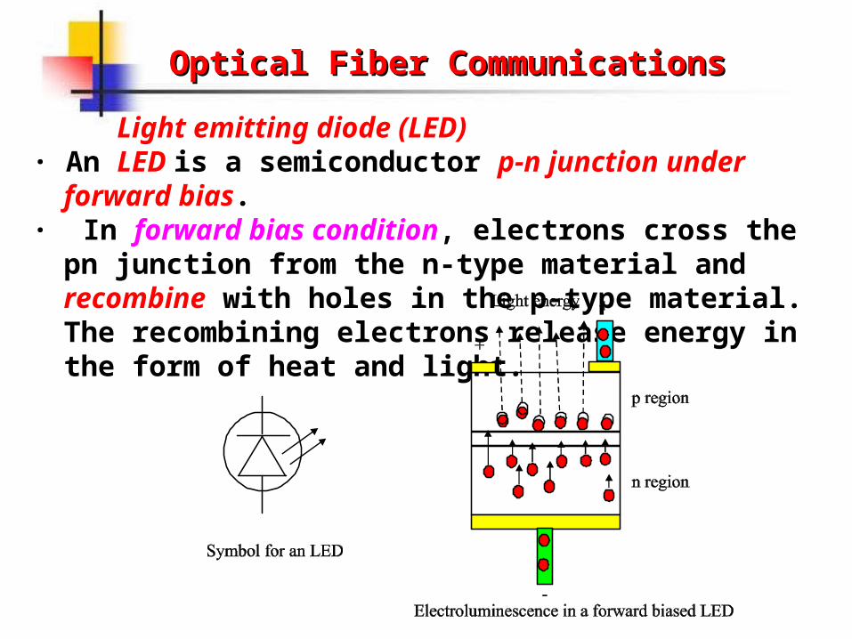
Light emitting diode (LED)· An LED is a semiconductor p-n junction under forward bias.· In forward bias condition, electrons cross the pn junction from
the n-type material and recombine with holes in the p-type material. The recombining electrons release energy in the form of heat and light.

Optical Fiber CommunicationsOptical Fiber Communications
Light emitting diode (LED)
Energy diagram:

Optical Fiber CommunicationsOptical Fiber Communications
Light emitting diode (LED)· In LED, the dominant photon generation is spontaneous
emission in which the electron drops to the lower energy level in an entirely random way. The output spectrum of an LED is relatively wide.

Optical Fiber CommunicationsOptical Fiber Communications
Spontaneous emissionAn atom in an excited level can make a downward
transition spontaneously (i.e., on its own) by emitting a photon corresponding to the energy difference between the two levels.

Optical Fiber CommunicationsOptical Fiber Communications
During spontaneous emission, the amount of energy emitted is equal to the difference between the two energy levels, E2 and E1, which is also the photon energy.
• Photon energyh = E2 – E1
where h = 6.626×10⁻³⁴ J•s is Planck’s constant

Optical Fiber CommunicationsOptical Fiber Communications
ExampleSuppose you use an LED whose energy gap equals 2.5 eV. What
is its radiating wavelength?Solution
1 eV = 1.602 ×10⁻¹⁹ J
Since the energy gap is the photon energy Ep, and Ep = h = hc /λ,
then ashc = 6.626×10⁻³⁴ J•s ×3×10⁸ m/s ≈20×10-26 m•J
Ep = 2.5 eV = 2.5 ×1.602×10-19 ≈ 4×10-19 JWe have
λ = hc / Ep = 20×10-26 m•J / 4×10-19 J = 5×10⁻⁷ m = 500 nm

Optical Fiber CommunicationsOptical Fiber Communications
The most frequently used light source in optical communication systems is laser.
Why we use a laser as the light source?(a) monochromatic: suitable for elimination of white
noise(b) coherent: suitable for coherent detection(c) high power: improves signal to noise ratio(d) small divergence: improves efficiency of
transmission(e) small source size: suitable for use with optical
fibres

Optical Fiber CommunicationsOptical Fiber Communications
LaserAn acronym for light amplification by stimulated
emission of radiation.
Stimulated emissionAn atom in an excited level can make a downward
transition in the presence of external stimulation by emitting a photon corresponding to the energy difference between the two levels. The emitted photon is in phase with the incident photon.

Optical Fiber CommunicationsOptical Fiber Communications
Stimulated emission

Optical Fiber CommunicationsOptical Fiber Communications
AbsorptionAn atom in a lower energy state can absorb photons
and make an upward transition to the higher energy level.

Optical Fiber CommunicationsOptical Fiber Communications
Population inversionIn laser operation, light amplification should be achieved, this needs that the population of the upper energy level is greater than that of the lower energy level, this condition is known as population inversion.

Optical Fiber CommunicationsOptical Fiber Communications
How to realize population inversion? --- By pumping techniques.
Pumping is to excite atoms into the upper energy level and hence obtain a nonequilibrium distribution by using the external source, such as a current
source, a light source etc.
Optical Fiber CommunicationsOptical Fiber Communications
Furthermore, a resonant cavity is needed to build up stimulated emission by use of feedback.
Optical feedback and laser oscillation• Light amplification occurs when a photon
colliding with an atom in the excited energy state causes the stimulated emission of a second photon, the two photons are in phase, and then both these photons release two more.
• A positive feedback mechanism has to be used to increase the net gain and achieve a laser light output.

Optical Fiber CommunicationsOptical Fiber Communications
Total reflector
Partial reflector
Some light escapes
Some light escapesThe rest is fed back
Eventually, equilibrium is established
Growth of stimulated emission in a resonant laser cavity

Optical Fiber CommunicationsOptical Fiber Communications
Light propagation in optical fibersThe simplest way to view light in fiber optics is by ray theory. In this theory, the light is treated as a simple ray, shown by a line.An arrow on the line shows the direction of propagation.
The speed of light in vacuum is: c = 300,000 km/s
However, the speed of light in medium is more slowly, v = c / n.
The ratio of the velocity of light, c, in vacuum, to the velocity of light in the medium, v, is the refractive index, n.
n = c / v

Optical Fiber CommunicationsOptical Fiber Communications
Light traveling from one material to another causes the change of speed, which results in the change of light traveling direction. This deflection of light is called refraction.
Optical Fiber CommunicationsOptical Fiber Communications
The relation between incident ray and reflection ray:r = i (Law of reflection)
The relation between incident ray and refraction ray:n1sini = n2sint (Snell’s law)
where n1 and n2 are refractive indices of the incident and transmission regions, respectively.
An interesting phenomenon can be found in the light refraction.

Optical Fiber CommunicationsOptical Fiber Communications

Optical Fiber CommunicationsOptical Fiber Communications
Total internal reflection
From Snell’s law, n1sini = n2sint if n1 > n2, then sini = (n2/n1) sint < sint, which leads to i < t, i.e. the angle of refraction is always greater than the angle of incidence.
Thus, when the angle of refraction t = 90, as sini = (n2/n1) sint = (n2/n1) sin90 = n2/n1 <
1the angle of incidence, i, must be less than 90.
Optical Fiber CommunicationsOptical Fiber Communications
Critical angle The angle of incidence that yields an angle of
refraction t = 90 is called the critical angle, C.sinC = n2/n1
When the angle of incidence is greater than the critical angle, the light will be reflected back into the originating dielectric medium.
This is known as total internal reflection.

Optical Fiber CommunicationsOptical Fiber Communications
ExampleA Beam of light is incident on a plane boundary between two dielectrics. The incident-ray angle is at 10º to the boundary normal and the transmitted beam is at 12º. Which of the two media has the higher refractive index?
SolutionFrom Snell’s lawsint / sini = n1 / n2
since t > i, then sint > sini and then we must have n1 > n2.
n 1n 2
1 2
1 0
Optical Fiber CommunicationsOptical Fiber Communications
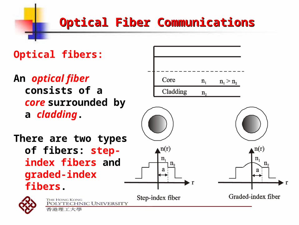
Optical fibers:
An optical fiber consists of a core surrounded by a cladding.
There are two types of fibers: step-index fibers and graded-index fibers.

Optical Fiber CommunicationsOptical Fiber Communications
Light guidingIn order to propagate a long distance in the optical fiber, the light
beam must satisfy the conditions for total internal reflection
Conditions for total internal reflection in optical fiberRefractive index of fiber core, n1, is greater than refractive index of fiber cladding n2, i.e. n1 > n2
The incident angle is larger than the critical angle. i > C
n1 > n2i i > C

Optical Fiber CommunicationsOptical Fiber Communications
How the light enter the optical fiber?
Acceptance angleAcceptance angle, a, is the maximum angle over which light
rays entering the fiber will be guided along its core.

Optical Fiber CommunicationsOptical Fiber Communications
The acceptance angle is usually measured as the numerical aperture (NA).
Numerical apertureAt the air-core interface,
n0sina = n1sin2 = n1sin(90 - C) = n1cosC = n1(1 – sin2C)1/2 = n1[1 – (n2/n1)2]1/2 = (n1
2 - n22)1/2 = NA
The value of NA represents the light collecting ability.

Optical Fiber CommunicationsOptical Fiber Communications
Example(a)What is the numerical aperture of silica fiber with n1 =
1.48 and n2 = 1.46 ?(b)What is the numerical aperture of plastic fiber where n1 =
1.495 and n2 = 1.402 ?
Solution(a) NA = (n1
2 - n22)1/2 = (1.482 – 1.462)1/2 = 0.2425
(b) NA = (n12 - n2
2)1/2 = (1.4952 – 1.4022)1/2 = 0.5192
* Notice the difference in the values of NA for these two fibers

Optical Fiber CommunicationsOptical Fiber Communications
Light propagation in graded-index fiber
It guides light by refraction. Its refractive index decreases gradually away from its center, dropping to the same as the cladding at the edge of the core.
The change in refractive index causes refraction, bending light rays back toward the axis as they pass through layers with lower refractive index.

Optical Fiber CommunicationsOptical Fiber Communications
The light beam with larger i experience total internal reflection earlier, light beam with smaller i travels longer distance until it experience total internal reflection.

Optical Fiber CommunicationsOptical Fiber Communications
Recall thatIn order to propagate a long distance in the optical fiber, the light beam must satisfy the conditions fortotal internal reflection
QuestionCan all the light beams propagate in the optical fiber for a long distance even if they satisfy the conditions for total internal reflection?

Optical Fiber CommunicationsOptical Fiber Communications
Answer
Only a set of separate beams at distinct propagation angles can propagate in the optical fiber for a long distance.
These different beams are called modes.

Optical Fiber CommunicationsOptical Fiber Communications
Modes in waveguidesFrom the theoretical standpoint, an optical fiber is a waveguide,
which confines light waves so they travel along the fiber.
Modes are stable patterns in which a wave can travel along a waveguide.

Optical Fiber CommunicationsOptical Fiber Communications
Two light beams in superposition
+
=
+
=

Optical Fiber CommunicationsOptical Fiber Communications
If two rays have the same initial phase, along with AC and BDEF respectively. The optical path difference (OPD) between the two rays is x = 2ndcosi.
Electromagnetic theory shows that there is a phase shift, , on reflection, so the total phase difference between the two rays is
t = kx = 2kndcosi - 2where k = 2/ is the propagation constant. When t = 2kndcosi - 2 = 2mthe two light beams produce a constructive interference. However,
this happens only for certain angle of incidence as
Rays with i satisfying above equation can travel along the waveguide and we say that they correspond to a waveguide mode.
cos 0, 1, 2, ,i
mm
nkd
Optical Fiber CommunicationsOptical Fiber Communications
Optical Fibres
The fibre that is dominantly used for long-distancetransmission is a step-index single mode optical
fibre .
The “single-mode” fibre transmits only one light ray.
The fiber core diameter of the single mode fiber is 8 – 12 m.

Optical Fiber CommunicationsOptical Fiber Communications

Optical Fiber CommunicationsOptical Fiber Communications
Transmission properties of optical fibers
The most important transmission properties of optical fiber are attenuation and dispersion.
Attenuation limits how far a signal can travel through a fiber before it becomes too weak to be detected.
How to measure the fiber attenuation?By the amount of light lost between input and output.

Optical Fiber CommunicationsOptical Fiber Communications
Fibre AttenuationFibre attenuation is a function of wavelength and itgives a measure of the loss suffered by the light in the fibre per km of length travelled. Theattenuation constant, , is given by
where L is the length of the fibre, Pin is the input light power and Pout is the output light power.
LPP inout //log10 10
Optical Fiber CommunicationsOptical Fiber Communications
Main types of fiber attenuation:Absorption, scattering and light coupling loss
Absorption• Absorption is related to the material composition and
the fabrication process for the fiber, which results in the dissipation of some of the transmitted optical power as heat in the waveguide.
Optical power → heat optical power loss

Optical Fiber CommunicationsOptical Fiber Communications
ScatteringScattering refers to the process by which the light wave encounters
a particle smaller than its wavelength, with the results that energy is sent to a new direction.

Optical Fiber CommunicationsOptical Fiber Communications
Bend lossBend loss is the loss resulting from bend. Bend can cause the
change of incident angle at which the light hits the core-cladding boundary.
Optical Fiber CommunicationsOptical Fiber Communications
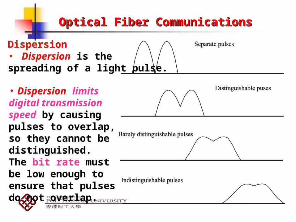
Dispersion• Dispersion is the spreading of a light pulse.
• Dispersion limits digital transmission speed by causing pulses to overlap, so they cannot be distinguished. The bit rate must be low enough to ensure that pulses do not overlap.

Optical Fiber CommunicationsOptical Fiber Communications
Three main types of dispersion
Material dispersionMaterial dispersion occurs because the refractive index of the
material changes with the optical wavelength.
As n = n(), and n = c / v, then v = c / n()
Different wavelength elements travel at different velocities through a fiber, even in the same mode.

Optical Fiber CommunicationsOptical Fiber Communications
Waveguide dispersionIt is equivalent to the angle between the ray and the fiber axis
varying with wavelength.
From
For a given mode (e.g. m = 1)
Different lead to different values of 1 and hence results in different transmission time (in the same mode).
1
( )cos
2nkd nd
cos 0, 1, 2, ,i
mm
nkd

Optical Fiber CommunicationsOptical Fiber Communications
Mode dispersion
Mode dispersion arises because raysfollow different pathsthrough the fiber andconsequently arrive at theother end of the fiber atdifferent times.
Different modes travel with different speeds.

Optical Fiber Communications
Optical Detectors• The optical detector performs the opposite function from
the source: It converts optical energy to electrical
energy.
The commonly used detector is the photodiode, which produces current in response to incident light.
P-N photodiode· The simplest photodiode is the p-n photodiode. It is
essentially a reverse biased p-n junction.

When the diode is reverse biased, the negative terminal of the battery attracts holes away from the pn junction, while the positive terminal attracts electrons away from the junction. the depletion region widensmore positive ions are created in the n region and more negative ions in the p region.
Reverse bias the diode
+-
D eple tion reg ion

Optical Fiber CommunicationsOptical Fiber Communications
A photon with an energy h Eg incident in or near the depletion region will excite an electron from valence band into the conduction band, and hence leave an empty hole in the valence band (photogeneration of an electron-hole pair).
Carrier pairs so generated near the junction are separated and swept (drift) under the influence of the electrical field to produce a current in the external circuit.

Optical Fiber Communications

Optical Fiber CommunicationsOptical Fiber Communications
Fibre-optic System DesignThe key system requirements which must be specified in system design are:(a) The desired (or possible) transmission
distance;(b) The data rate (channel bandwidth); and(c) The bit error rate.
Thus, link power budget and bandwidth budget analyses need to be carried out to ensure that the desired system performance can be achieved.

Optical Fiber CommunicationsOptical Fiber Communications
The Power Budget
The power budget calculation determines whether the power produced by the transmitter will be adequate to overcome the fibre loss and the other losses so that an adequate amount of light reaches the detector (in order to achieve a minimum bit error rate).

Optical Fiber CommunicationsOptical Fiber Communications
The Bandwidth BudgetThe other consideration is to determine whether the system bandwidth will be adequate. Since there is an inverse relationship between the bandwidth and the rise time, the system rise time limit can be expressed as
where ts, tt, tf, and tr are respectively the rise times of the system, the transmitter, the fibre and the receiver.
222rfts tttt

Optical Fiber CommunicationsOptical Fiber Communications
Rise timeThe rise time, tr, is the time it takes for the output to change from 10% to 90% of its final value when the input is a step function
trtf
Amplitudetw
Pulse width
90%
10%

_______________________________________________________________________________________________________________
Example:
The specifications of the components used in a 80-km fibre-optic transmission link are given as follows:
Transmitter : Emission wavelength = 1550 nm Spectral width = 0.1 nm
Output power delivered to fibre = + 10 dBm (1 mW = 0 dBm)
Rise-time = 0.1 ns = 100 ps
Receiver : Rise-time = 0.1 ns = 100psMinimum power at 10 Gbps (BER = 10-9)
= 30 dBm
Fibre: Total length: 80 km, Attenuation = 0.3 dB/km, Dispersion = 2 ps/nm/km at 1550 nm
Connector loss per km of fibre: 0.25 dB
Determine whether the system can successfully transmit a bit rate of 10 Gbps by performing power and rise-time budget calculations. Assume a maximum bit rate of 0.7 / (total system rise-time).

Solution:
The input power to receiver is 34 dBm (10 24 20 dB) which is less than the required power ( 30 dBm). Therefore, there is a shortfall in the power budget. The system rise-time is: (1 ps = 10-12 s)
ps1421025610 44

Solution:
Therefore, the maximum bit rate is 0.7 / 142 10-12 = 4.9 109 or4.9 Gbps. This is not within the required bandwidth budget (i.e. it is less than 10 Gbps, which means that the system would also notconform to requirement as far as bandwidth is concerned.) The bandwidth and the power budget requirements are not met, therefore, this system is not viable unless some changes to loss or power and also the rise-time are made.

Questions (Optical fiber Questions (Optical fiber Communications)Communications)
Questions1. What are the key advantages of optical fiber communication
system?2. Describe an optical fiber. What is its function in a
telecommunication system?3. What is refractive index? What is the refractive index of a
vacuum?4. Describe the functions of core and the cladding in an optical
fiber. Why are their refractive indexes different? Which one has to be greater and why?
5. Why is it necessary to meet the total internal reflection requirement inside an optical fiber?
6. What is the acceptance angle? Why do we need to know what this angle is?

Questions (Optical fiber Questions (Optical fiber Communications)Communications)
Questions7. What is attenuation in an optical fiber? List of three major
causes of attenuation in an optical fiber and explain its mechanisms.
8. What is dispersion? What are main types of dispersion in an optical fiber?
9. What is spontaneous emission?10. Explain the working principle of LED.11. What is stimulated emission?12. What is population inversion? How to realize it?13. What is the function of optical detector?14. Explain the operating principle of a P-N photodiode.15. How to carry out power budget and bandwidth budget
analysis in the optical fiber communication system design?

Problems (Optical Fiber Communications)
1. Suppose a laser diode radiates red light with wavelength of 650nm. What is the energy of a single photon?
2. Assume you have a glass rod surrounded by air as shown. Find the critical incident angle.
3. What is the acceptance angle for the fiber when n1 = 1.48 and n2 = 1.46?
4. For a specific fiber NA = 0.275 and n1 = 1.490. Find the critical propagation angle which is equal to 90º - θC .
g la s s ro d : n = 1 .61
a ir : n = 12

Solutions (Optical Fiber Communications)
1. Ep = hf = hc/ = (6.6 10-34 3 108)/650 10-9 = 3.04 10-19 J
2. From Snell’s law, n1 sin1 = n2 sin2 Since n1 = 1.6, n2 = 1.0, while 2 = 90, we have
1c = arcsin (1/1.6) = 38.68

Solutions (Optical Fiber Communications)
3. From Snell’s law, n0 sina = n1 sin2. For air, n0 = 1.0. The critical angle sinc = n2/n1.
Since 2 = 90 - c, sinc = cos2; hence cos2 = n2/n1. Thus sin2 = [1- (n2/n1)2]1/2
sina = n1 [1- (n2/n1)2]1/2 = 1.48 [1 – (1.46/1.48)2]1/2 = 0.2425 a = 14.033
The whole acceptance angle is: 2a = 28.07

Problems (Optical Fiber Communications)
4. n2 = [n12 - NA2]1/2 = [1.492 – 0.2752]1/2 = 1.4644,
c = arcsin (n2 / n1) = arcsin (0.98282) = 79.4
90º - c = 10.6


