
78-18343-02
C H A P T E R 4
Optical Amplifier CardsThis chapter describes the optical amplifier cards used in Cisco ONS 15454 dense wavelength division multiplexing (DWDM) networks. For installation and card turn-up procedures, refer to the Cisco ONS 15454 DWDM Procedure Guide. For card safety and compliance information, refer to the Cisco Optical Transport Products Safety and Compliance Information document.
Note Unless otherwise specified, “ONS 15454” refers to both ANSI and ETSI shelf assemblies.
Chapter topics include:
• 4.1 Card Overview, page 4-1
• 4.2 Class 1M Laser Safety Labels, page 4-3
• 4.3 OPT-PRE Amplifier Card, page 4-5
• 4.4 OPT-BST Amplifier Card, page 4-9
• 4.5 OPT-BST-E Amplifier Card, page 4-13
• 4.6 OPT-BST-L Amplifier Card, page 4-17
• 4.7 OPT-AMP-L Card, page 4-21
• 4.8 OPT-AMP-17-C Card, page 4-26
• 4.9 OPT-AMP-C Card, page 4-30
4.1 Card OverviewThis section provides summary and compatibility information for the optical amplifier cards.
Note Each card is marked with a symbol that corresponds to a slot (or slots) on the ONS 15454 shelf assembly. Cards should be installed in slots that have the same symbols. See the “1.16.1 Card Slot Requirements” section on page 1-61 for a list of slots and symbols.
Optical amplifiers are used in amplified nodes (such as hub nodes), amplified OADM nodes, and line amplifier nodes. The seven types of ONS 15454 DWDM amplifiers are:
• Optical Preamplifier (OPT-PRE)
• Optical Booster amplifier (OPT-BST)
4-1Cisco ONS 15454 DWDM Reference Manual, R8.5

Chapter 4 Optical Amplifier Cards4.1.1 Card Summary
• Optical Booster Enhanced amplifier (OPT-BST-E)
• Optical Booster L-Band amplifier (OPT-BST-L)
• Optical L-Band preamplifier (OPT-AMP-L)
• Optical C-Band amplifier (OPT-AMP-17-C).
• Optical C-band high-gain high-power amplicier (OPT-AMP-C)
Note The OPT-AMP-L preamplifier, OPT-AMP-C and OPT-AMP-17-C amplifiers are software-configurable as a preamplifier or as a booster amplifier.
Optical amplifier card architecture includes an optical plug-in module with a controller that manages optical power, laser current, and temperature control loops. An amplifier also manages communication with the TCC2/TCC2P card and operation, administration, maintenance, and provisioning (OAM&P) functions such as provisioning, controls, and alarms.
4.1.1 Card SummaryTable 4-1 lists and summarizes the functions of each optical amplifier card.
Table 4-1 Optical Amplifier Cards for the ONS 15454
Card Port Description For Additional Information
OPT-PRE The OPT-PRE amplifier has five optical ports (three sets) located on the faceplate. It operates in Slots 1 to 6 and 12 to 17.
See the “4.3 OPT-PRE Amplifier Card” section on page 4-5.
OPT-BST The OPT-BST amplifier has four sets of optical ports located on the faceplate. It operates in Slots 1 to 6 and 12 to 17.
See the “4.4 OPT-BST Amplifier Card” section on page 4-9.
OPT-BST-E The OPT-BST-E amplifier has four sets of optical ports located on the faceplate. It operates in Slots 1 to 6 and 12 to 17.
See the “4.5 OPT-BST-E Amplifier Card” section on page 4-13.
OPT-BST-L The OPT-BST-L L-band amplifier has four sets of optical ports located on the faceplate. It operates in Slots 1 to 6 and 12 to 17.
See the “4.6 OPT-BST-L Amplifier Card” section on page 4-17.
OPT-AMP-L The OPT-AMP-L L-band preamplifier have five sets of optical ports located on the faceplate. It is a two-slot card that operates in Slots 1 to 6 and 12 to 17.
See the “4.7 OPT-AMP-L Card” section on page 4-21.
4-2Cisco ONS 15454 DWDM Reference Manual, R8.5
78-18343-02

Chapter 4 Optical Amplifier Cards4.1.2 Card Compatibility
4.1.2 Card CompatibilityTable 4-2 lists the Cisco Transport Controller (CTC) software compatibility for each optical amplifier card.
4.2 Class 1M Laser Safety LabelsThis section explains the significance of the safety labels attached to the optical amplifier cards. The faceplates of the cards are clearly labeled with warnings about the laser radiation levels. You must understand all warning labels before working on these cards.
4.2.1 Class 1M Laser Product LabelFigure 4-1 shows the Class 1M Laser Product label. Class 1M lasers are products that produce either a highly divergent beam or a large diameter beam. Therefore, only a small part of the whole laser beam can enter the eye. However, these laser products can be harmful to the eye if the beam is viewed using magnifying optical instruments.
OPT-AMP-17-C The OPT-AMP-17-C C-band low-gain preamplifier/booster amplifier has four sets of optical ports located on the faceplate. It operates in Slots 1 to 6 and 12 to 17.
See the “4.8 OPT-AMP-17-C Card” section on page 4-26.
OPT-AMP-C The OPT-AMP-C C-band high-gain, high-power preamplifier/booster amplifier has five sets of optical ports located on the faceplate. It operates as a preamplifier when equipped and provisioned in Slots 2 to 6 and 11 to 16 or as a booster amplifier when equipped and provisioned in Slot 1 and 17.
See the “4.9 OPT-AMP-C Card” section on page 4-30.
Table 4-1 Optical Amplifier Cards for the ONS 15454 (continued)
Card Port Description For Additional Information
Table 4-2 Software Release Compatibility for Optical Amplifier Cards
Card Type R4.5 R4.6 R4.7 R5.0 R6.0 R7.0 R7.2 R8.0 R8.5
OPT-PRE Yes Yes Yes Yes Yes Yes Yes Yes Yes
OPT-BST Yes Yes Yes Yes Yes Yes Yes Yes Yes
OPT-BST-E No No Yes Yes Yes Yes Yes Yes Yes
OPT-BST-L No No No No No Yes Yes Yes Yes
OPT-AMP-L No No No No No Yes Yes Yes Yes
OPT-AMP-17-C No No No No No No No Yes Yes
OPT-AMP-C No No No No No No No No Yes
4-3Cisco ONS 15454 DWDM Reference Manual, R8.5
78-18343-02

Chapter 4 Optical Amplifier Cards4.2.2 Hazard Level 1M Label
Figure 4-1 Class 1M Laser Product Label
4.2.2 Hazard Level 1M LabelFigure 4-2 shows the Hazard Level 1M label. The Hazard Level label warns users against exposure to laser radiation calculated in accordance with IEC60825-1 Ed.1.2.
Figure 4-2 Hazard Level Label
4.2.3 Laser Source Connector LabelFigure 4-3 shows the Laser Source Connector label. This label indicates that a laser source is present at the optical connector where the label appears.
Figure 4-3 Laser Source Connector Label
4.2.4 FDA Statement LabelFigure 4-4 shows the FDA Statement label. This label represents compliance to FDA standards and a hazard-level classification in accordance with IEC60825-1 Am.2 or Ed.1.2.
CAUTIONHAZARD LEVEL 1M INVISIBLE
LASER RADIATIONDO NOT VIEW DIRECTLY WITHNON-ATTENUATING OPTICAL
INSTRUMENTS λ =λ = 1400nm TO 1610nm
1459
53
HAZARDLEVEL 1M
1459
90
9663
5
4-4Cisco ONS 15454 DWDM Reference Manual, R8.5
78-18343-02

Chapter 4 Optical Amplifier Cards4.2.5 Shock Hazard Label
Figure 4-4 FDA Statement Label
4.2.5 Shock Hazard LabelFigure 4-5 shows the Shock Hazard label. This label alerts you to an electrical hazard within the card. The potential for shock exists when you remove adjacent cards during maintenance or touch exposed electrical circuity on the card.
Figure 4-5 Shock Hazard Label
4.3 OPT-PRE Amplifier Card
Note For hardware specifications, see the “A.5.1 OPT-PRE Amplifier Card Specifications” section on page A-14.
Note For OPT-PRE card safety labels, see the “4.2 Class 1M Laser Safety Labels” section on page 4-3.
The OPT-PRE is a C-band, DWDM, two-stage erbium-doped fiber amplifier (EDFA) with midamplifier loss (MAL) that can be connected to a dispersion compensating unit (DCU). The OPT-PRE is equipped with a built-in variable optical attenuator (VOA) that controls the gain tilt and can also be used to pad the DCU to a reference value. You can install the OPT-PRE in Slots 1 to 6 and 12 to 17. The card is designed to support up to 80 channels at 50-GHz channel spacing. The OPT-PRE features include:
• Fixed gain mode with programmable tilt
• True variable gain
• Fast transient suppression
• Nondistorting low-frequency transfer function
• Settable maximum output power
9663
4
COMPLIES WITH 21 CFR 1040.10AND 1040.11 EXCEPT FOR
DEVIATIONS PURSUANT TOLASER NOTICE NO.50,DATED JULY 26, 2001
6554
1
4-5Cisco ONS 15454 DWDM Reference Manual, R8.5
78-18343-02

Chapter 4 Optical Amplifier Cards4.3.1 OPT-PRE Faceplate Ports
• Fixed output power mode (mode used during provisioning)
• MAL for fiber-based DCU
• Amplified spontaneous emissions (ASE) compensation in fixed gain mode
• Full monitoring and alarm handling with settable thresholds
• Four signal photodiodes to monitor the input and output optical power of the two amplifier stages through CTC
• An optical output port for external monitoring
Note The optical splitter has a ratio of 1:99, resulting in about 20 dB-lower power at the MON port than at the COM TX port.
4.3.1 OPT-PRE Faceplate Ports The OPT-PRE amplifier has five optical ports located on the faceplate:
• MON is the output monitor port
• COM RX (receive) is the input signal port
• COM TX (transmit) is the output signal port
• DC RX is the MAL input signal port
• DC TX is the MAL output signal port
4-6Cisco ONS 15454 DWDM Reference Manual, R8.5
78-18343-02
Chapter 4 Optical Amplifier Cards4.3.2 OPT-PRE Block Diagrams
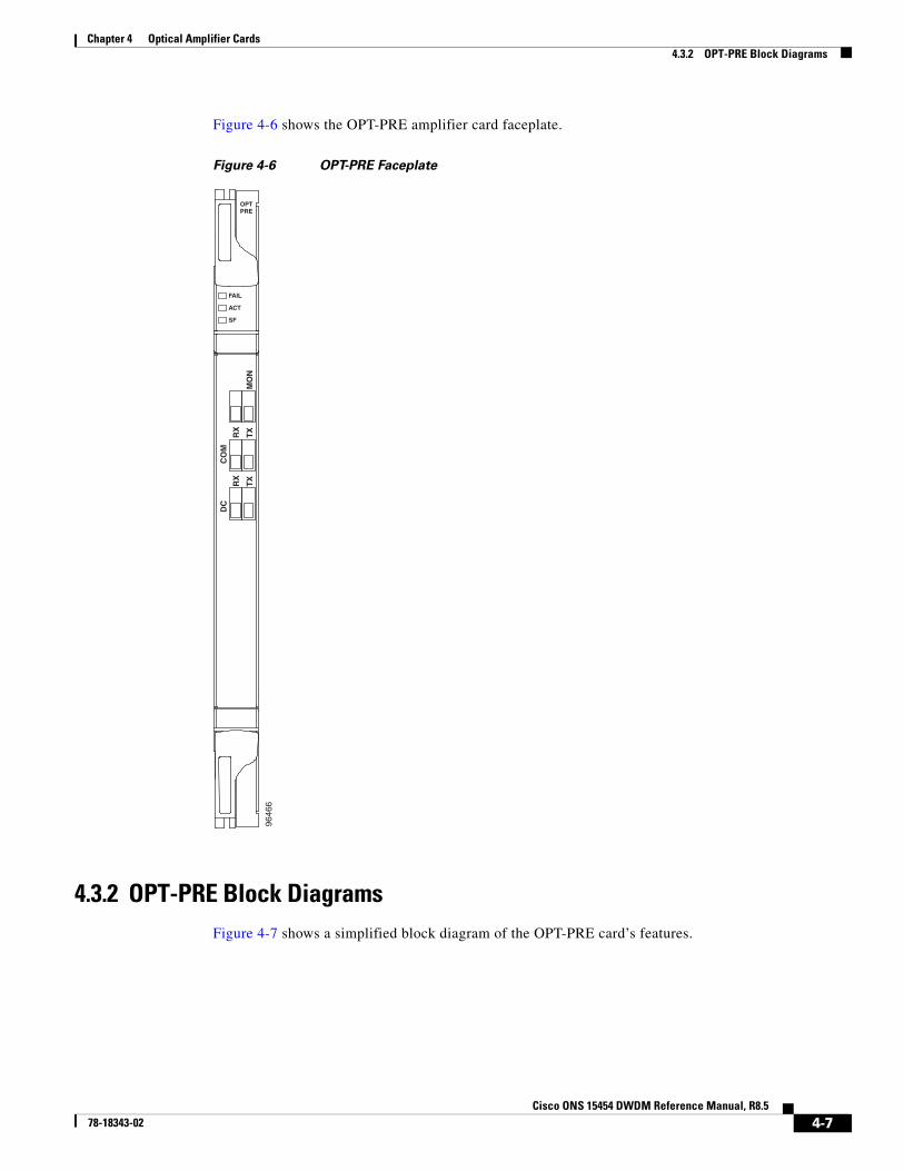
Figure 4-6 shows the OPT-PRE amplifier card faceplate.
Figure 4-6 OPT-PRE Faceplate
4.3.2 OPT-PRE Block DiagramsFigure 4-7 shows a simplified block diagram of the OPT-PRE card’s features.
OPTPRE
FAIL
ACT
SF
MO
N
RX
CO
M
TX
RX
DC
TX
9646
6
4-7Cisco ONS 15454 DWDM Reference Manual, R8.5
78-18343-02

Chapter 4 Optical Amplifier Cards4.3.3 OPT-PRE Power Monitoring
Figure 4-7 OPT-PRE Block Diagram
Figure 4-8 shows the a block diagram of how the OPT-PRE optical module functions.
Figure 4-8 OPT-PRE Optical Module Functional Block Diagram
4.3.3 OPT-PRE Power MonitoringPhysical photodiodes P1, P2, P3, and P4 monitor the power for the OPT-PRE card. Table 4-3 shows the returned power level values calibrated to each port.
Opticalmodule
COM RX
DC RX
9647
8
Processor
DC TX
COM TX
MON
FPGAFor SCL Busmanagement
SCL BusTCCi M
SCL BusTCCi P
DC/DCPower supplyInput filters
BAT A&B
9829
8DCU
COM RX COM TX
DC RXDC TXMON
P1 P2 P3 P4
P Physical photodiode
Variable optical attenuator
Table 4-3 OPT-PRE Port Calibration
Photodiode CTC Type Name Calibrated to Port
P1 Input Com COM RX
P2 Output DC DC TX
P3 Input DC DC RX
P4 Output COM (Total Output) COM TX
Output COM (Signal Output)
4-8Cisco ONS 15454 DWDM Reference Manual, R8.5
78-18343-02

Chapter 4 Optical Amplifier Cards4.3.4 OPT-PRE Amplifier Card-Level Indicators
For information on the associated TL1 AIDs for the optical power monitoring points, refer the “CTC Port Numbers and TL1 Aids” section in Cisco ONS SONET TL1 Command Guide, Release 8.5.
4.3.4 OPT-PRE Amplifier Card-Level IndicatorsTable 4-4 shows the three card-level LED indicators on the OPT-PRE amplifier card.
4.3.5 OPT-PRE Ampifier Port-Level IndicatorsYou can determine the status of the card ports using the LCD screen on the ONS 15454 fan-tray assembly. Use the LCD to view the status of any port or card slot; the screen displays the number and severity of alarms for a given port or slot.
4.4 OPT-BST Amplifier Card
Note For hardware specifications, see the “A.5.2 OPT-BST Amplifier Card Specifications” section on page A-15.
Note For OPT-BST card safety labels, see the “4.2 Class 1M Laser Safety Labels” section on page 4-3.
The OPT-BST is designed to ultimately support up to 80 channels at 50-GHz channel spacing. The OPT-BST is a C-band, DWDM EDFA with optical service channel (OSC) add-and-drop capability. When an OPT-BST installed in the an ONS 15454, an OSCM card is also needed to process the OSC. You can install the OPT-BST in Slots 1 to 6 and 12 to 17. The card’s features include:
• Fixed gain mode (with programmable tilt)
• Gain range of 5 to 20 dB in constant gain mode and output power mode
• True variable gain
• Built-in VOA to control gain tilt
• Fast transient suppression
Table 4-4 OPT-PRE Amplifier Card-Level Indicators
Card-Level Indicators Description
Red FAIL LED The red FAIL LED indicates that the card’s processor is not ready or that an internal hardware failure occurred. Replace the card if the red FAIL LED persists.
Green ACT LED The green ACT LED indicates that the OPT-PRE is carrying traffic or is traffic-ready.
Amber SF LED The amber SF LED indicates a signal failure or condition such as LOS on one or more of the card’s ports. The amber SF LED also turns on when the transmit and receive fibers are incorrectly connected. When the fibers are properly connected, the light turns off.
4-9Cisco ONS 15454 DWDM Reference Manual, R8.5
78-18343-02

Chapter 4 Optical Amplifier Cards4.4.1 OPT-BST Faceplate Ports
• Nondistorting low-frequency transfer function
• Settable maximum output power
• Fixed output power mode (mode used during provisioning)
• ASE compensation in fixed gain mode
• Full monitoring and alarm handling with settable thresholds
• Optical Safety Remote Interlock (OSRI), a CTC software feature capable of shutting down optical output power or reducing the power to a safe level (automatic power reduction)
• Automatic laser shutdown (ALS), a safety mechanism used in the event of a fiber cut. For details on ALS provisioning for the card, refer to the Cisco ONS 15454 DWDM Procedure Guide. For information about using the card to implement ALS in a network, see the “10.7 Network Optical Safety” section on page 10-18.
Note The optical splitters each have a ratio of 1:99. The result is that MON TX and MON RX port power is about 20 dB lower than COM TX and COM RX port power.
4.4.1 OPT-BST Faceplate PortsThe OPT-BST amplifier has eight optical ports located on the faceplate:
• MON RX is the output monitor port (receive section).
• MON TX is the output monitor port.
• COM RX is the input signal port.
• LINE TX is the output signal port.
• LINE RX is the input signal port (receive section).
• COM TX is the output signal port (receive section).
• OSC RX is the OSC add input port.
• OSC TX is the OSC drop output port.
4-10Cisco ONS 15454 DWDM Reference Manual, R8.5
78-18343-02

Chapter 4 Optical Amplifier Cards4.4.2 OPT-BST Block Diagrams
Figure 4-9 shows the OPT-BST amplifier card faceplate.
Figure 4-9 OPT-BST Faceplate
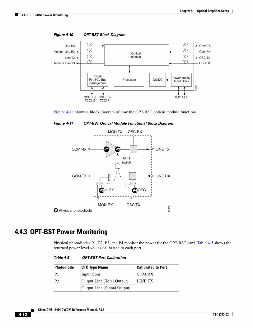
4.4.2 OPT-BST Block DiagramsFigure 4-10 shows a simplified block diagram of the OPT-BST card’s features.
OPTBST
FAIL
ACT
SF
RX
MO
N
TX
RX
CO
M
TX
RX
OS
C
TX
RX
LIN
E
TX
9646
7
4-11Cisco ONS 15454 DWDM Reference Manual, R8.5
78-18343-02
Chapter 4 Optical Amplifier Cards4.4.3 OPT-BST Power Monitoring
Figure 4-10 OPT-BST Block Diagram
Figure 4-11 shows a block diagram of how the OPT-BST optical module functions.
Figure 4-11 OPT-BST Optical Module Functional Block Diagram
4.4.3 OPT-BST Power MonitoringPhysical photodiodes P1, P2, P3, and P4 monitor the power for the OPT-BST card. Table 4-5 shows the returned power level values calibrated to each port.
Opticalmodule
Line RX
Monitor Line RX
9647
9
Processor
Line TX
COM TX
Com RX
OSC TX
Monitor Line TX OSC RX
FPGAFor SCL Busmanagement
SCL BusTCCi M
SCL BusTCCi P
DC/DCPower supplyInput filters
BAT A&B
9830
0
MON TX OSC RX
MON RX OSC TX
OSC
COM RX P1 P2
P3 P4
COM TX
LINE TX
APRsignal
LINE RX
in RX
P Physical photodiode
Table 4-5 OPT-BST Port Calibration
Photodiode CTC Type Name Calibrated to Port
P1 Input Com COM RX
P2 Output Line (Total Output) LINE TX
Output Line (Signal Output)
4-12Cisco ONS 15454 DWDM Reference Manual, R8.5
78-18343-02

Chapter 4 Optical Amplifier Cards4.4.4 OPT-BST Card-Level Indicators
For information on the associated TL1 AIDs for the optical power monitoring points, refer the “CTC Port Numbers and TL1 Aids” section in Cisco ONS SONET TL1 Command Guide, Release 8.5.
4.4.4 OPT-BST Card-Level IndicatorsTable 4-6 describes the three card-level LED indicators on the OPT-BST card.
4.4.5 OPT-BST Port-Level IndicatorsYou can determine the status of the card ports using the LCD screen on the ONS 15454 fan-tray assembly. Use the LCD to view the status of any port or card slot; the screen displays the number and severity of alarms for a given port or slot.
4.5 OPT-BST-E Amplifier Card
Note For hardware specifications, see the “A.5.3 OPT-BST-E Amplifier Card Specifications” section on page A-15.
Note For OPT-BST-E safety labels, see the “4.2 Class 1M Laser Safety Labels” section on page 4-3.
The OPT-BST-E amplifier card is a gain-enhanced version of the OPT-BST card. It is designed to support up to 80 channels at 50-GHz channel spacing. The OPT-BST-E is a C-band, DWDM EDFA with OSC add-and-drop capability. When an OPT-BST-E installed, an OSCM card is needed to process the OSC. You can install the OPT-BST-E in Slots 1 to 6 and 12 to 17. The card’s features include:
P3 Output COM LINE RX
P4 Output OSC
Table 4-5 OPT-BST Port Calibration (continued)
Photodiode CTC Type Name Calibrated to Port
Table 4-6 OPT-BST Card-Level Indicators
Card-Level Indicators Description
Red FAIL LED The red FAIL LED indicates that the card’s processor is not ready or that an internal hardware failure occurred. Replace the card if the red FAIL LED persists.
Green ACT LED The green ACT LED indicates that the OPT-BST is carrying traffic or is traffic-ready.
Amber SF LED The amber SF LED indicates a signal failure or condition such as LOS on one or more of the card’s ports. The amber SF LED also turns on when the transmit and receive fibers are incorrectly connected. When the fibers are properly connected, the light turns off.
4-13Cisco ONS 15454 DWDM Reference Manual, R8.5
78-18343-02

Chapter 4 Optical Amplifier Cards4.5.1 OPT-BST-E Faceplate Ports
• Fixed gain mode (with programmable tilt)
• True variable gain
• Gain range of 8 to 23 dBm with the tilt managed at 0 dBm in constant gain mode and output power mode
• Enhanced gain range of 23 to 26 dBm with unmanaged tilt
• Built-in VOA to control the gain tilt
• Fast transient suppression
• Nondistorting low-frequency transfer function
• Settable maximum output power
• Fixed output power mode (mode used during provisioning)
• ASE compensation in fixed gain mode
• Full monitoring and alarm handling with settable thresholds
• OSRI
• ALS
Note The optical splitters each have a ratio of 1:99. The result is that MON TX and MON RX port power is about 20 dB lower than COM TX and COM RX port power.
4.5.1 OPT-BST-E Faceplate PortsThe OPT-BST-E amplifier card has eight optical ports located on the faceplate:
• MON RX is the output monitor port (receive section).
• MON TX is the output monitor port.
• COM RX is the input signal port.
• LINE TX is the output signal port.
• LINE RX is the input signal port (receive section).
• COM TX is the output signal port (receive section).
• OSC RX is the OSC add input port.
• OSC TX is the OSC drop output port.
4-14Cisco ONS 15454 DWDM Reference Manual, R8.5
78-18343-02

Chapter 4 Optical Amplifier Cards4.5.2 OPT-BST-E Block Diagrams
Figure 4-12 shows the OPT-BST-E amplifier card faceplate.
Figure 4-12 OPT-BST-E Faceplate
4.5.2 OPT-BST-E Block DiagramsFigure 4-13 shows a simplified block diagram of the OPT-BST-E card’s features.
OPTBST-E
FAIL
ACT
SF
RX
MO
N
TX
RX
CO
M
TX
RX
OS
C
TX
RX
LIN
E
TX
1459
39
4-15Cisco ONS 15454 DWDM Reference Manual, R8.5
78-18343-02

Chapter 4 Optical Amplifier Cards4.5.3 OPT-BST-E Power Monitoring
Figure 4-13 OPT-BST-E Block Diagram
Figure 4-14 shows a block diagram of how the OPT-BST-E optical module functions.
Figure 4-14 OPT-BST-E Optical Module Functional Block Diagram
4.5.3 OPT-BST-E Power MonitoringPhysical photodiodes P1, P2, P3, and P4 monitor the power for the OPT-BST-E card. Table 4-7 shows the returned power level values calibrated to each port.
Opticalmodule
Line RX
Monitor Line RX
9647
9
Processor
Line TX
COM TX
Com RX
OSC TX
Monitor Line TX OSC RX
FPGAFor SCL Busmanagement
SCL BusTCCi M
SCL BusTCCi P
DC/DCPower supplyInput filters
BAT A&B
9830
0
MON TX OSC RX
MON RX OSC TX
OSC
COM RX P1 P2
P3 P4
COM TX
LINE TX
APRsignal
LINE RX
in RX
P Physical photodiode
Table 4-7 OPT-BST-E Port Calibration
Photodiode CTC Type Name Calibrated to Port
P1 Input Com COM RX
P2 Output Line (Total Output) LINE TX
Output Line (Signal Output)
4-16Cisco ONS 15454 DWDM Reference Manual, R8.5
78-18343-02

Chapter 4 Optical Amplifier Cards4.5.4 OPT-BST-E Card-Level Indicators
For information on the associated TL1 AIDs for the optical power monitoring points, refer the “CTC Port Numbers and TL1 Aids” section in Cisco ONS SONET TL1 Command Guide, Release 8.5.
4.5.4 OPT-BST-E Card-Level IndicatorsTable 4-8 describes the three card-level LED indicators on the OPT-BST-E amplifier card.
4.5.5 OPT-BST-E Port-Level IndicatorsYou can determine the status of the card ports using the LCD screen on the ONS 15454 fan-tray assembly. Use the LCD to view the status of any port or card slot; the screen displays the number and severity of alarms for a given port or slot.
4.6 OPT-BST-L Amplifier Card
Note For hardware specifications, see the “A.5.4 OPT-BST-L Amplifier Card Specifications” section on page A-16.
Note For OPT-BST-L safety labels, see the “4.2 Class 1M Laser Safety Labels” section on page 4-3.
The OPT-BST-L is an L-band, DWDM EDFA with OSC add-and-drop capability. The card is well suited for use in networks that employ dispersion shifted (DS) fiber or SMF-28 single-mode fiber. The OPT-BST-L is designed to ultimately support 64 channels at 50-GHz channel spacing, but in
P3 Output COM LINE RX
P4 Output OSC
Table 4-7 OPT-BST-E Port Calibration (continued)
Photodiode CTC Type Name Calibrated to Port
Table 4-8 OPT-BST-E Card-Level Indicators
Card-Level Indicators Description
Red FAIL LED The red FAIL LED indicates that the card’s processor is not ready or that an internal hardware failure occurred. Replace the card if the red FAIL LED persists.
Green ACT LED The green ACT LED indicates that the OPT-BST-E is carrying traffic or is traffic-ready.
Amber SF LED The amber SF LED indicates a signal failure or condition such as LOS on one or more of the card’s ports. The amber SF LED also turns on when the transmit and receive fibers are incorrectly connected. When the fibers are properly connected, the light turns off.
4-17Cisco ONS 15454 DWDM Reference Manual, R8.5
78-18343-02

Chapter 4 Optical Amplifier Cards4.6.1 OPT-BST-L Faceplate Ports
Software R8.5 and earlieris limited to 32 channels at 100-GHz spacing.When an ONS 15454 has an OPT-BST-L installed, an OSCM card is needed to process the OSC. You can install the OPT-BST-L in Slots 1 to 6 and 12 to 17. The card’s features include:
• Fixed gain mode (with programmable tilt)
• Standard gain range of 8 to 20 dB in the programmable gain tilt mode
• True variable gain
• 20 to 27 dB gain range in the uncontrolled gain tilt mode
• Built-in VOA to control gain tilt
• Fast transient suppression
• Nondistorting low-frequency transfer function
• Settable maximum output power
• Fixed output power mode (mode used during provisioning)
• ASE compensation in fixed gain mode
• Full monitoring and alarm handling with settable thresholds
• OSRI
• ALS
Note The optical splitters each have a ratio of 1:99. The result is that MON TX and MON RX port power is about 20 dB lower than COM TX and COM RX port power.
4.6.1 OPT-BST-L Faceplate PortsThe OPT-BST-L amplifier has eight optical ports located on the faceplate:
• MON RX is the output monitor port (receive section).
• MON TX is the output monitor port.
• COM RX is the input signal port.
• LINE TX is the output signal port.
• LINE RX is the input signal port (receive section).
• COM TX is the output signal port (receive section).
• OSC RX is the OSC add input port.
• OSC TX is the OSC drop output port.
4-18Cisco ONS 15454 DWDM Reference Manual, R8.5
78-18343-02

Chapter 4 Optical Amplifier Cards4.6.2 OPT-BST-L Block Diagrams
Figure 4-15 shows the OPT-BST-L card faceplate.
Figure 4-15 OPT-BST-L Faceplate
4.6.2 OPT-BST-L Block DiagramsFigure 4-16 shows a simplified block diagram of the OPT-BST-L card’s features.
OPTBST-L
FAIL
ACT
SF
RX
MO
N
TX
RX
CO
M
TX
RX
OS
C
TX
RX
LIN
E
TX
1809
29
4-19Cisco ONS 15454 DWDM Reference Manual, R8.5
78-18343-02

Chapter 4 Optical Amplifier Cards4.6.3 OPT-BST-L Power Monitoring
Figure 4-16 OPT-BST-L Block Diagram
Figure 4-17 shows a block diagram of how the OPT-BST-L optical module functions.
Figure 4-17 OPT-BST-L Optical Module Functional Block Diagram
4.6.3 OPT-BST-L Power MonitoringPhysical photodiodes P1, P2, P3, P4, and P5 monitor the power for the OPT-BST-L card. Table 4-9 shows the returned power level values calibrated to each port.
Opticalmodule
Line RX
Monitor Line RX
1809
30
Processor
Line TX
COM TX
COM RX
OSC TX
Monitor Line TX OSC RX
FPGAFor SCL Busmanagement
SCL BusTCCi M
SCL BusTCCi P
DC/DCPower supply
Input filters
BAT A&B
1349
76
MON TX OSC RX
MON RX OSC TX
OSC
COM RX P1 P2
P4 P5
COM TX
LINE TX
APRsignal
LINE RX
in RX
P Physical photodiode
P3
Table 4-9 OPT-BST-L Port Calibration
Photodiode CTC Type Name Calibrated to Port
P1 Input COM COM RX
4-20Cisco ONS 15454 DWDM Reference Manual, R8.5
78-18343-02

Chapter 4 Optical Amplifier Cards4.6.4 OPT-BST-L Card-Level Indicators
For information on the associated TL1 AIDs for the optical power monitoring points, refer the “CTC Port Numbers and TL1 Aids” section in Cisco ONS SONET TL1 Command Guide, Release 8.5.
4.6.4 OPT-BST-L Card-Level IndicatorsTable 4-10 shows the three card-level LEDs on the OPT-BST-L card.
4.6.5 OPT-BST-L Port-Level IndicatorsYou can determine the status of the card ports using the LCD screen on the ONS 15454 fan-tray assembly. Use the LCD to view the status of any port or card slot; the screen displays the number and severity of alarms for a given port or slot.
4.7 OPT-AMP-L Card
Note For hardware specifications, see the “A.5.5 OPT-AMP-L Preamplifier Card Specifications” section on page A-17.
Note For OPT-AMP-L card safety labels, see the “4.2 Class 1M Laser Safety Labels” section on page 4-3.
P2 Output Line (Total Output) LINE TX
Output Line (Signal Output)
P3 Output OSC-RX OSC-RX
P4 Output COM LINE RX
P5 Output OSC-TX
Table 4-9 OPT-BST-L Port Calibration (continued)
Photodiode CTC Type Name Calibrated to Port
Table 4-10 OPT-BST-L Card-Level Indicators
Card-Level Indicators Description
Red FAIL LED The red FAIL LED indicates that the card’s processor is not ready or that an internal hardware failure occurred. Replace the card if the red FAIL LED persists.
Green ACT LED The green ACT LED indicates that the OPT-BST-L is carrying traffic or is traffic-ready.
Amber SF LED The amber SF LED indicates a signal failure or condition such as LOS on one or more of the card’s ports. The amber SF LED also turns on when the transmit and receive fibers are incorrectly connected. When the fibers are properly connected, the light turns off.
4-21Cisco ONS 15454 DWDM Reference Manual, R8.5
78-18343-02

Chapter 4 Optical Amplifier Cards4.7.1 OPT-AMP-L Faceplate Ports
The OPT-AMP-L is an L-band, DWDM optical amplifier card consisting of a two-stage EDFA with midstage access loss (MSL) for an external DCU and OSC add-and-drop capability. Using CTC, the card is provisionable as a preamplifier (OPT-PRE) or booster amplifier (OPT-BST), and is well suited for use in networks that employ DS or SMF-28 fiber. The amplifier can operate up to 64 optical transmission channels at 50-GHz channel spacing in the 1570 nm to 1605 nm wavelength range.
When an OPT-AMP-L installed, an OSCM card is needed to process the OSC. You can install the two-slot OPT-AMP-L in Slots 1 to 6 and 12 to 17.
The card has the following features:
• Maximum power output of 20 dBm
• True variable gain amplifier with settable range from 12 to 24 dBm in the standard gain range and 24 dBm to 35 dbM with uncontrolled gain tilt
• Built-in VOA to control gain tilt
• Up to 12 dBm MSL for an external DCU
• Fast transient suppression; able to adjust power levels in hundreds of microseconds to avoid bit errors in failure or capacity growth situations
• Nondistorting low frequency transfer function
• Midstage access loss for dispersion compensation unit
• Constant pump current mode (test mode)
• Constant output power mode (used during optical node setup)
• Constant gain mode
• Internal ASE compensation in constant gain mode and in constant output power mode
• Full monitoring and alarm handling capability
• Optical safety support through signal loss detection and alarm at any input port, fast power down control (less than one second), and reduced maximum output power in safe power mode. For details on ALS provisioning for the card, refer to the Cisco ONS 15454 DWDM Procedure Guide. For information on using the card to implement ALS in a network, see the “10.7 Network Optical Safety” section on page 10-18.
Note Before disconnecting any OPT AMP-L fiber for troubleshooting, first make sure the OPT AMP-L card is unplugged.
4.7.1 OPT-AMP-L Faceplate PortsThe OPT-AMP-L amplifier card has ten optical ports located on the faceplate:
• MON RX is the output monitor port (receive section).
• MON TX is the output monitor port.
• COM RX is the input signal port.
• LINE TX is the output signal port.
• LINE RX is the input signal port (receive section).
• COM TX is the output signal port (receive section).
• OSC RX is the OSC add input port.
4-22Cisco ONS 15454 DWDM Reference Manual, R8.5
78-18343-02

Chapter 4 Optical Amplifier Cards4.7.2 OPT-AMP-L Block Diagrams
• OSC TX is the OSC drop output port.
• DC TX is the output signal to the DCU.
• DC RX is the input signal from the DCU.
Figure 4-18 shows the OPT-AMP-L card faceplate.
Figure 4-18 OPT-AMP-L Faceplate
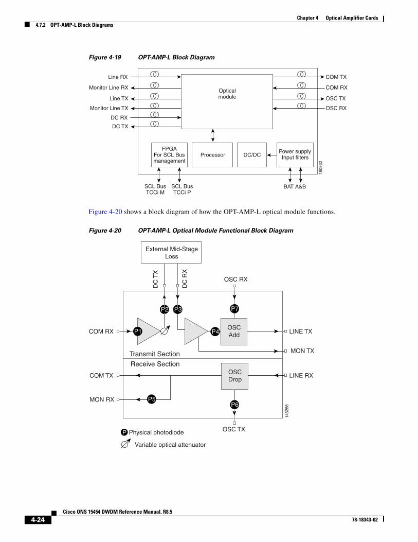
4.7.2 OPT-AMP-L Block DiagramsFigure 4-19 shows a simplified block diagram of the OPT-AMP-L card’s features.
OPT-AMP-L
FAIL
ACT
SF
RX
MO
N
TX
RX
CO
M
TX
RX
OS
C
TX
RX
LIN
E
TX
RX
DC
TX
1809
31
4-23Cisco ONS 15454 DWDM Reference Manual, R8.5
78-18343-02
Chapter 4 Optical Amplifier Cards4.7.2 OPT-AMP-L Block Diagrams
Figure 4-19 OPT-AMP-L Block Diagram
Figure 4-20 shows a block diagram of how the OPT-AMP-L optical module functions.
Figure 4-20 OPT-AMP-L Optical Module Functional Block Diagram
Opticalmodule
Monitor Line RX
Line RX
DC RX
Processor
Line TX
DC TX
COM TX
COM RX
OSC TX
Monitor Line TX OSC RX
FPGAFor SCL Busmanagement
SCL BusTCCi M
SCL BusTCCi P
DC/DCPower supplyInput filters
BAT A&B
1809
32
MON TX
OSC RX
OSC TX
COM RX
COM TX
MON RX
LINE TX
LINE RX
P1
P Physical photodiode
Variable optical attenuator
P2 P3
P6
P4
DC
TX
DC
RX
External Mid-StageLoss
OSCAdd
OSCDrop
P7
P5
Transmit Section
Receive Section
1452
56
4-24Cisco ONS 15454 DWDM Reference Manual, R8.5
78-18343-02

Chapter 4 Optical Amplifier Cards4.7.3 OPT-AMP-L Power Monitoring
4.7.3 OPT-AMP-L Power MonitoringPhysical photodiodes P1 through P7 monitor the power for the OPT-AMP-L card. Table 4-11 shows the returned power level values calibrated to each port.
For information on the associated TL1 AIDs for the optical power monitoring points, refer the “CTC Port Numbers and TL1 Aids” section in Cisco ONS SONET TL1 Command Guide, Release 8.5.
4.7.4 OPT-AMP-L Card-Level IndicatorsTable 4-12 shows the three card-level LEDs on the OPT-AMP-L card.
4.7.5 OPT-AMP-L Port-Level IndicatorsYou can determine the status of the card ports using the LCD screen on the ONS 15454 fan-tray assembly. Use the LCD to view the status of any port or card slot; the screen displays the number and severity of alarms for a given port or slot.
Table 4-11 OPT-AMP-L Port Calibration
Photodiode CTC Type Name Calibrated to Port
P1 Input COM Power COM RX
P2 Output DC (total power) DC TX
Output DC (signal power)
P3 Input DC (input power) DC RX
P4 Output Line Transmit (total power) LINE TX
Output Line Transmit (signal power)
P5 Input Line Receive Power LINE RX
P6 Output OSC Receive Power OSC RX
P7 Input OSC Transmit Power
Table 4-12 OPT-AMP-L Card-Level Indicators
Card-Level Indicators Description
Red FAIL LED The red FAIL LED indicates that the card’s processor is not ready or that an internal hardware failure occurred. Replace the card if the red FAIL LED persists.
Green ACT LED The green ACT LED indicates that the OPT-AMP-L is carrying traffic or is traffic-ready.
Amber SF LED The amber SF LED indicates a signal failure or condition such as LOS on one or more of the card’s ports. The amber SF LED also turns on when the transmit and receive fibers are incorrectly connected. When the fibers are properly connected, the light turns off.
4-25Cisco ONS 15454 DWDM Reference Manual, R8.5
78-18343-02

Chapter 4 Optical Amplifier Cards4.8 OPT-AMP-17-C Card
4.8 OPT-AMP-17-C Card
Note For hardware specifications, see the “A.5.6 OPT-AMP-17-C Amplifier Card Specifications” section on page A-17.
Note For OPT-AMP-17-C safety labels, see the “4.2 Class 1M Laser Safety Labels” section on page 4-3.
The OPT-AMP-17-C is a 17-dB gain, C-band, DWDM EDFA amplifier/preamplifier with OSC add-and-drop capability. It supports 80 channels at 50-GHz channel spacing in the C-band (that is, the 1529 nm to 1562.5 nm wavelength range). When an ONS 15454 has an OPT-AMP-17-C installed, an OSCM card is needed to process the OSC. You can install the OPT-AMP-17-C in Slots 1 to 6 and 12 to 17.
The card’s features include:
• Fixed gain mode (no programmable tilt)
• Standard gain range of 14 to 20 dB at startup when configured as a preamplifier
• Standard gain range of 20 to 23 dB in the transient mode when configured as a preamplifier
• Gain range of 14 to 23 dB (with no transient gain range) when configured as a booster amplifier
• True variable gain
• Fast transient suppression
• Nondistorting low-frequency transfer function
• Settable maximum output power
• Fixed output power mode (mode used during provisioning)
• ASE compensation in fixed gain mode
• Full monitoring and alarm handling with settable thresholds
• OSRI
• ALS
4.8.1 OPT-AMP-17-C Faceplate PortsThe OPT-AMP-17-C amplifier card has eight optical ports located on the faceplate:
• MON RX is the output monitor port (receive section).
• MON TX is the output monitor port.
• COM RX is the input signal port.
• LINE TX is the output signal port.
• LINE RX is the input signal port (receive section).
• COM TX is the output signal port (receive section).
• OSC RX is the OSC add input port.
• OSC TX is the OSC drop output port.
4-26Cisco ONS 15454 DWDM Reference Manual, R8.5
78-18343-02

Chapter 4 Optical Amplifier Cards4.8.2 OPT-AMP-17-C Block Diagrams
Figure 4-21 shows the OPT-AMP-17-C amplifier card faceplate.
Figure 4-21 OPT-AMP-17-C Faceplate
4.8.2 OPT-AMP-17-C Block DiagramsFigure 4-22 shows a simplified block diagram of the OPT-AMP-17C card’s features.
OPT-AMP17-C
FAIL
ACT
SF
RX
MO
N
TX
RX
CO
M
TX
RX
OS
C
TX
RX
LIN
E
TX
1595
20
4-27Cisco ONS 15454 DWDM Reference Manual, R8.5
78-18343-02

Chapter 4 Optical Amplifier Cards4.8.3 OPT-AMP-17-C Automatic Power Control
Figure 4-22 OPT-AMP17-C Block Diagram
Figure 4-23 shows how the OPT-AMP-17-C optical module functions.
Figure 4-23 OPT-AMP-17-C Optical Module Functional Block Diagram
4.8.3 OPT-AMP-17-C Automatic Power ControlA transient gain range of 20 to 23 dB is available to APC in order to permit other amplifiers to reach their expected set points. However, operation in this range is not continuous. At startup, the OPT-AMP-17-C card caps the gain at a maximum of 20 dB.
Opticalmodule
Line RX
Monitor Line RX
1809
28
Processor
Line TX
COM TX
COM RX
OSC TX
Monitor Line TX OSC RX
FPGAFor SCL Busmanagement
SCL BusTCCi M
SCL BusTCCi P
DC/DCPower supply
Input filters
BAT A&B
MON TX OSC RX
MON RX OSC TX
OSC
COM RX
P1
P2
P4
P5
COM TX
LINE TX
APRsignal
LINE RX
in RX
P Physical photodiode
P3
OSCadd
OSCdrop
1595
19
4-28Cisco ONS 15454 DWDM Reference Manual, R8.5
78-18343-02

Chapter 4 Optical Amplifier Cards4.8.4 OPT-AMP-17-C Power Monitoring
Note When the OPT-AMP-17-C operates as a booster amplifier, APC does not control its gain.
4.8.4 OPT-AMP-17-C Power MonitoringPhysical photodiodes P1, P2, P3, P4, and P5 monitor power for the OPT-AMP-17-C card. Table 4-13 shows the returned power level values calibrated to each port.
For information on the associated TL1 AIDs for the optical power monitoring points, refer the “CTC Port Numbers and TL1 Aids” section in Cisco ONS SONET TL1 Command Guide, Release 8.5.
4.8.5 OPT-AMP-17-C Card-Level IndicatorsTable 4-14 shows the three card-level LEDs on the OPT-AMP-17-C card.
4.8.6 OPT-AMP-17-C Port-Level IndicatorsYou can determine the status of the card ports using the LCD screen on the ONS 15454 fan-tray assembly. Use the LCD to view the status of any port or card slot; the screen displays the number and severity of alarms for a given port or slot.
Table 4-13 OPT-AMP-17-C Port Calibration
Photodiode CTC Type Name Calibrated to Port
P1 Input COM COM RX
P2 Output Line (Total Output) LINE TX
Output Line (Signal Output)
P5 Output OSC-RX OSC-RX
P3 Output COM LINE RX
P4 Output OSC-TX
Table 4-14 OPT-AMP-17-C Card-Level Indicators
Card-Level Indicators Description
Red FAIL LED The red FAIL LED indicates that the card’s processor is not ready or that an internal hardware failure occurred. Replace the card if the red FAIL LED persists.
Green ACT LED The green ACT LED indicates that the OPT-AMP-17-C is carrying traffic or is traffic-ready.
Amber SF LED The amber SF LED indicates a signal failure or condition such as LOS on one or more of the card’s ports. The amber SF LED also turns on when the transmit and receive fibers are incorrectly connected. When the fibers are properly connected, the light turns off.
4-29Cisco ONS 15454 DWDM Reference Manual, R8.5
78-18343-02
Chapter 4 Optical Amplifier Cards4.9 OPT-AMP-C Card
4.9 OPT-AMP-C Card
Note For hardware specifications, see the “A.5.7 OPT-AMP-C Amplifier Card Specifications” section on page A-18.
Note For OPT-AMP-C card safety labels, see the “4.2 Class 1M Laser Safety Labels” section on page 4-3.
The OPT-AMP-C card is a 20-dB output power, C-band, DWDM EDFA amplifier/preamplifier. It contains mid-stage access loss for a Dispersion Compensation Unit (DCU). To control gain tilt, a VOA is used. The VOA can also be used to attenuate the signal to the DCU to a reference value. The amplifier module also includes the OSC add (TX direction) and drop (RX direction) optical filters.
The OPT-AMP-C card supports 80 channels at 50-GHz channel spacing in the C-band (that is, the 1529 nm to 1562.5 nm wavelength range). When an ONS 15454 has an OPT-AMP-C card installed, an OSCM card is needed to process the OSC. You can install the OPT-AMP-C card in Slots 1 to 6 and 12 to 17. Slots 2 to 6 and Slots 12 to 16 are the default slots for provisioning the OPT-AMP-C card as a preamplifier, and slots 1 and 17 are the default slots for provisioning the OPT-AMP-C card as a booster amplifier.
The card’s features include:
• Fast transient suppression
• Nondistorting low-frequency transfer function
• Mid-stage access for DCU
• Constant pump current mode (test mode)
• Fixed output power mode (mode used during provisioning)
• Constant gain mode
• ASE compensation in Constant Gain and Constant Output Power modes
• Programmable tilt
• Full monitoring and alarm handling capability
• Gain range with gain tilt control of 12 to 24 dB
• Extended gain range (with uncontrolled tilt) of 24 to 35 dB
• Full monitoring and alarm handling with settable thresholds
• OSRI
• ALS
4.9.1 OPT-AMP-C Card Faceplate PortsThe OPT-AMP-C amplifier card has 10 optical ports located on the faceplate:
• MON RX is the output monitor port (receive section).
• MON TX is the output monitor port.
• COM RX is the input signal port.
4-30Cisco ONS 15454 DWDM Reference Manual, R8.5
78-18343-02

Chapter 4 Optical Amplifier Cards4.9.1 OPT-AMP-C Card Faceplate Ports
• COM TX is the output signal port (receive section).
• DC RX is the input DCU port.
• DC TX is the output DCU port.
• OSC RX is the OSC add input port.
• OSC TX is the OSC drop output port.
• LINE RX is the input signal port (receive section).
• LINE TX is the output signal port.
Figure 4-24 shows the OPT-AMP-C amplifier card faceplate.
Figure 4-24 OPT-AMP-C Card Faceplate
OPT-AMP
-C
FAIL
ACT
SF
RX
MON
TX
RX
COM
TX
RX
OSC
TX
RX
DC
TX
RX
LINE
TX
2745
10
4-31Cisco ONS 15454 DWDM Reference Manual, R8.5
78-18343-02

Chapter 4 Optical Amplifier Cards4.9.2 OPT-AMP-C Card Block Diagrams
4.9.2 OPT-AMP-C Card Block DiagramsFigure 4-25 shows a simplified block diagram of the OPT-AMP-17C card features.
Figure 4-25 OPT-AMP-C Block Diagram
Figure 4-26 shows how the OPT-AMP-C optical module functions.
Figure 4-26 OPT-AMP-C Optical Module Functional Block Diagram
Opticalmodule
Line RX
Monitor Line RX
2403
56
Processor
COM TX
COM RX
OSC TXLine TX
Monitor Line TX
DCU TX
DCU RX
OSC RX
FPGAFor SCL Busmanagement
SCL BusTCCi M
SCL BusTCCi P
DC/DCPower supply
Input filters
BAT A&B
MON-RX
COM-TX
COM-TX LINE-TX
MON-TX
LINE-RX
Transmittingsection
Receivingsection
2745
06
PD1 PD2 OSCadd
OSCdrop
PD6 PD7 PD5
PD3PD4
DC-TX DC-RXOSC-RX
OSC-TX
External Mid Stage Loss
4-32Cisco ONS 15454 DWDM Reference Manual, R8.5
78-18343-02

Chapter 4 Optical Amplifier Cards4.9.3 OPT-AMP-C Card Power Monitoring
4.9.3 OPT-AMP-C Card Power MonitoringPhysical photodiodes P1 through P7 monitor the power for the OPT-AMP-C card (see Table 4-15).
For information on the associated TL1 AIDs for the optical power monitoring points, refer the “CTC Port Numbers and TL1 Aids” section in Cisco ONS SONET TL1 Command Guide, Release 8.5.
4.9.4 OPT-AMP-C Card-Level IndicatorsTable 4-14 shows the three card-level LEDs on the OPT-AMP-C card.
4.9.5 OPT-AMP-C Card Port-Level IndicatorsYou can determine the status of the card ports using the LCD screen on the ONS 15454 fan-tray assembly. Use the LCD to view the status of any port or card slot; the screen displays the number and severity of alarms for a given port or slot.
Table 4-15 OPT-AMP-C Port Calibration
Photodiode CTC Type Name Calibrated to Port
P1 Input COM Power COM RX
P2 Output Line Transmit (total power) Line TX
Output Line Transmit (signal power)
P3 Input Line Receive Power Line RX
P4 Input OSC Receive Power
P5 Output OSC Transmit Power OSC-RX
P6 Output DC Transmit (total power) DC-TX
Output DC Transmit (signal power)
P7 Input DC Receive Power DC-RX
Table 4-16 OPT-AMP-C Card-Level Indicators
Card-Level Indicators Description
Red FAIL LED The red FAIL LED indicates that the card’s processor is not ready or that an internal hardware failure occurred. Replace the card if the red FAIL LED persists.
Green ACT LED The green ACT LED indicates that the OPT-AMP-C card is carrying traffic or is traffic-ready.
Amber SF LED The amber SF LED indicates a signal failure or condition such as LOS on one or more of the card’s ports. The amber SF LED also turns on when the transmit and receive fibers are incorrectly connected. When the fibers are properly connected, the light turns off.
4-33Cisco ONS 15454 DWDM Reference Manual, R8.5
78-18343-02

Chapter 4 Optical Amplifier Cards4.9.5 OPT-AMP-C Card Port-Level Indicators
4-34Cisco ONS 15454 DWDM Reference Manual, R8.5
78-18343-02


