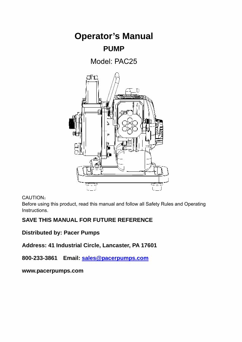
Operator’s Manual PUMP
Model: PAC25
CAUTION: Before using this product, read this manual and follow all Safety Rules and Operating Instructions.
SAVE THIS MANUAL FOR FUTURE REFERENCE
Distributed by: Pacer Pumps
Address: 41 Industrial Circle, Lancaster, PA 17601
800-233-3861 Email: [email protected]
www.pacerpumps.com
1. PREFACE Dear customer: Thank you for your choosing our gasoline engine driven pump. Please read and follow this manual carefully. Failure to do so could result in unsatisfactory performance, shortened pump life or personal injury.
2. WARNING AND SAFETY Read carefully before use and keep it for future reference.
2.1 Training Read the instructions carefully. Be familiar with all the controls and proper use of the machine.
2.2 OPERATION 1. Use proper gasoline to oil mixture. 2. Do not shut off engine at high speed. Slow to an idle before turning off. 3. Do not operate the pump while people, especially children, or pets are nearby. 4. This pump is intended for pumping water. Do not pump caustics or acids. 5. Do not run the engine without liquid in pump. Doing so will damage the pump. 6. During break in period of first 30 hours do not overload the engine. 7. Pumping caustic liquid is to be strictly forbidden.
2.4 maintenance and storage
1. Turn off engine to cool before repairing 2. Do not modify your engine, which may cause engine damage and personal
hazard. 3. Please use original parts recommended by manufacturer. to order parts, contact
your dealer or Pacer Pumps. 4. Service engine regularly 5. Properly prepare the pump before storage.
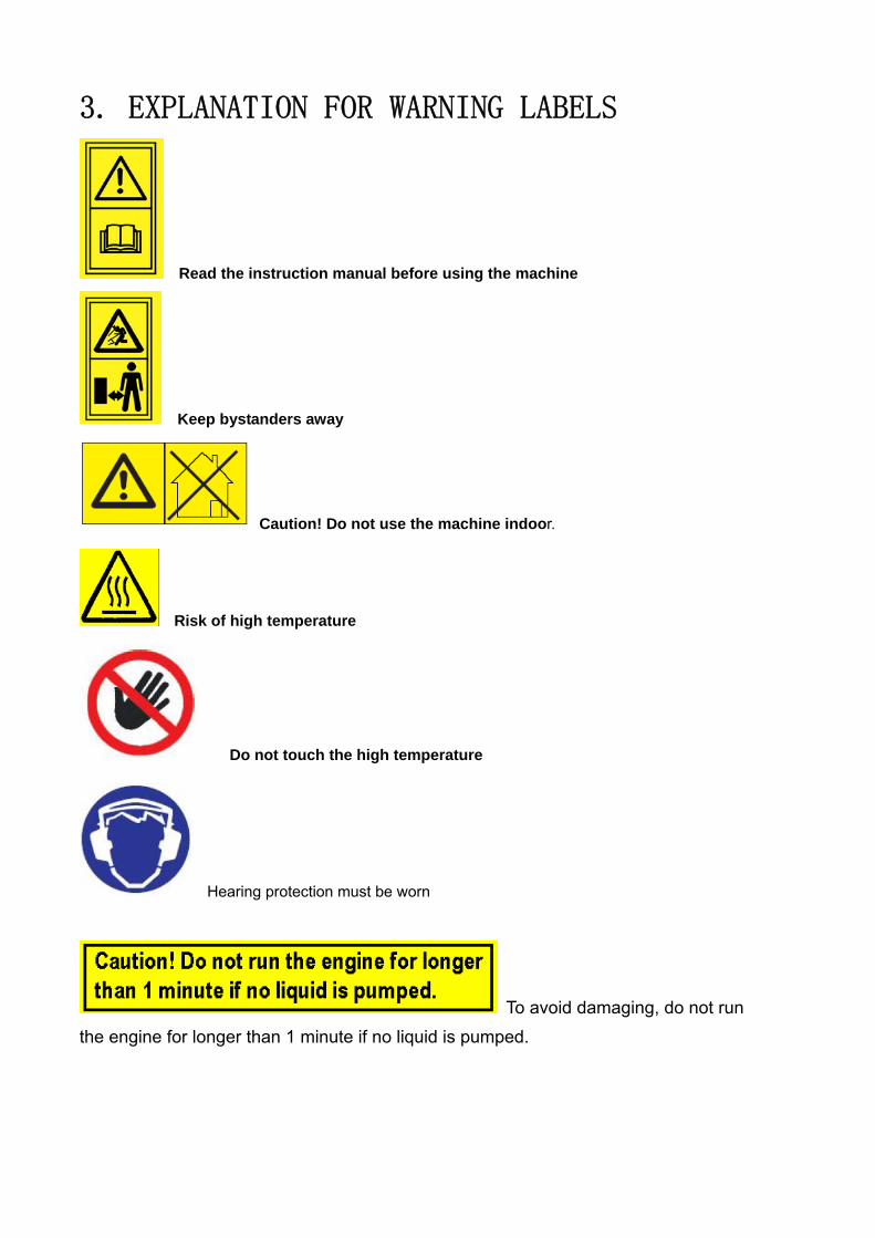
3. EXPLANATION FOR WARNING LABELS
Read the instruction manual before using the machine
Keep bystanders away
Caution! Do not use the machine indoor.
Risk of high temperature
Do not touch the high temperature
Hearing protection must be worn
To avoid damaging, do not run the engine for longer than 1 minute if no liquid is pumped.
4. TECHNICAL DATA MODEL PAC25 Net weight (lb) 13 Engine type 1E34F Rated speed (rpm/kw) 2000rpm/0.7kw Displacement (cc) 25.4cc Fuel type Unleaded / oil mixture Mixture ratio (volume) 40:1 Fuel tank capacity(oz) 24 Spark plug model BM6A L7 RTC Start mode Recoil Maximum flow rate (gph) 1500 Max discharge head (ft) 57 Self-suction time(s) ≤60s Bore x stroke(mm) 34×28 Cooling system air cooling Diameter of suction pipe 1 inch Diameter of discharge pipe 1 inch Suction lift (ft) 16
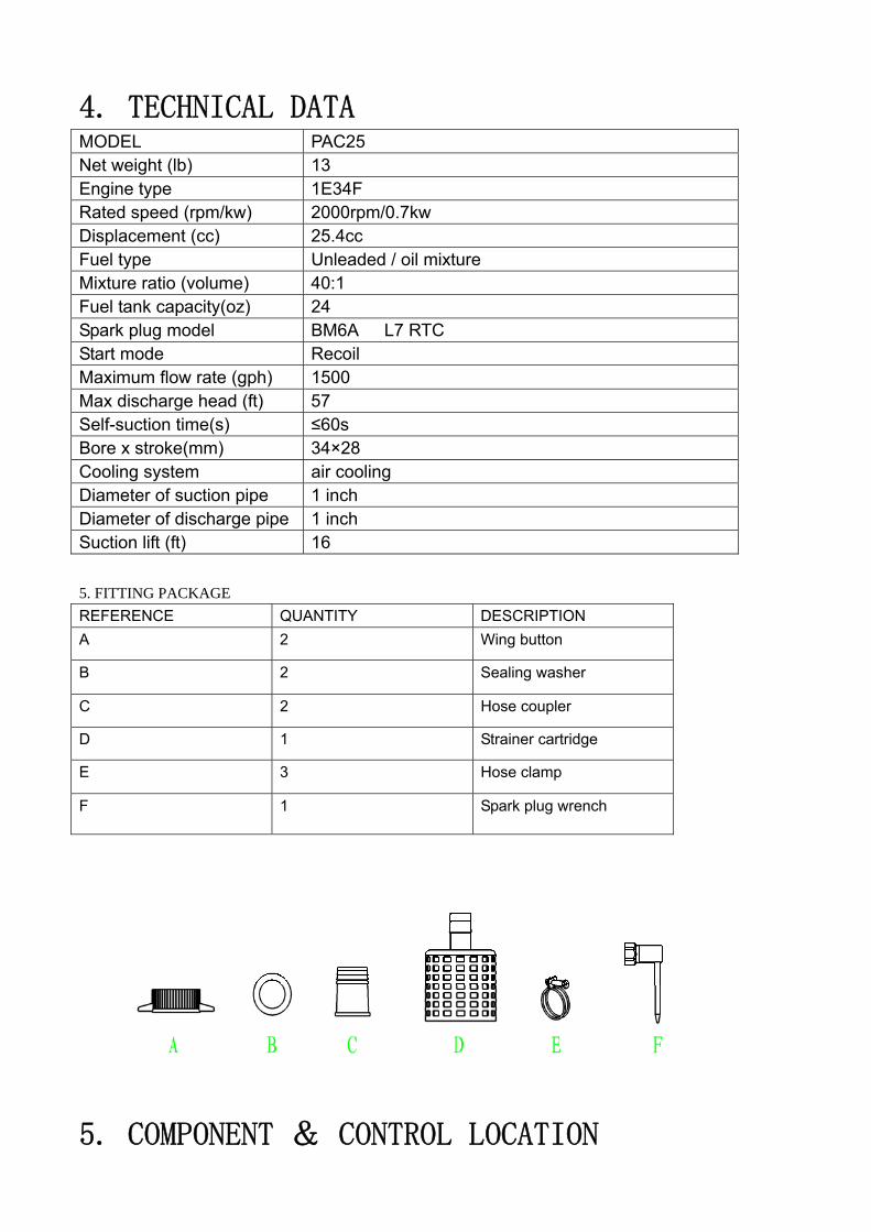
5. FITTING PACKAGE REFERENCE QUANTITY DESCRIPTION A 2 Wing button
B 2 Sealing washer
C 2 Hose coupler
D 1 Strainer cartridge
E 3 Hose clamp
F 1 Spark plug wrench
5. COMPONENT & CONTROL LOCATION

CONTROLS
Ignition Switch
The ignition switch can turn off the ignition system.
Push the ignition switch for stopping the engine.
Choke Lever
The choke lever is in charge of controls of opening and closing choke valve in

the air cleaner.
Turn the choke level to CLOSE position to enrich the fuel mixture for starting a cold engine.
Turn the choke lever to OPEN position for forming a correct fuel mixture after starting a cold engine or for restarting a warm engine.
Throttle Lever
The throttle lever controls engine speed Turning the throttle lever in the direction such as the figure below will adjust the speed.
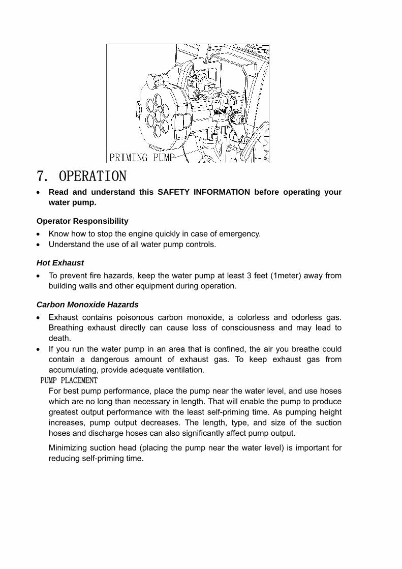
Priming bulb
The priming bulb pumps fuel from fuel tank to carburetor for easy-starting.
Press five-six times on the priming bulb to draw fuel from tank to carburetor
7. OPERATION
• Read and understand this SAFETY INFORMATION before operating your water pump.
Operator Responsibility • Know how to stop the engine quickly in case of emergency. • Understand the use of all water pump controls.
Hot Exhaust • To prevent fire hazards, keep the water pump at least 3 feet (1meter) away from
building walls and other equipment during operation.
Carbon Monoxide Hazards • Exhaust contains poisonous carbon monoxide, a colorless and odorless gas.
Breathing exhaust directly can cause loss of consciousness and may lead to death.
• If you run the water pump in an area that is confined, the air you breathe could contain a dangerous amount of exhaust gas. To keep exhaust gas from accumulating, provide adequate ventilation.
PUMP PLACEMENT
For best pump performance, place the pump near the water level, and use hoses which are no long than necessary in length. That will enable the pump to produce greatest output performance with the least self-priming time. As pumping height increases, pump output decreases. The length, type, and size of the suction hoses and discharge hoses can also significantly affect pump output.
Minimizing suction head (placing the pump near the water level) is important for reducing self-priming time.
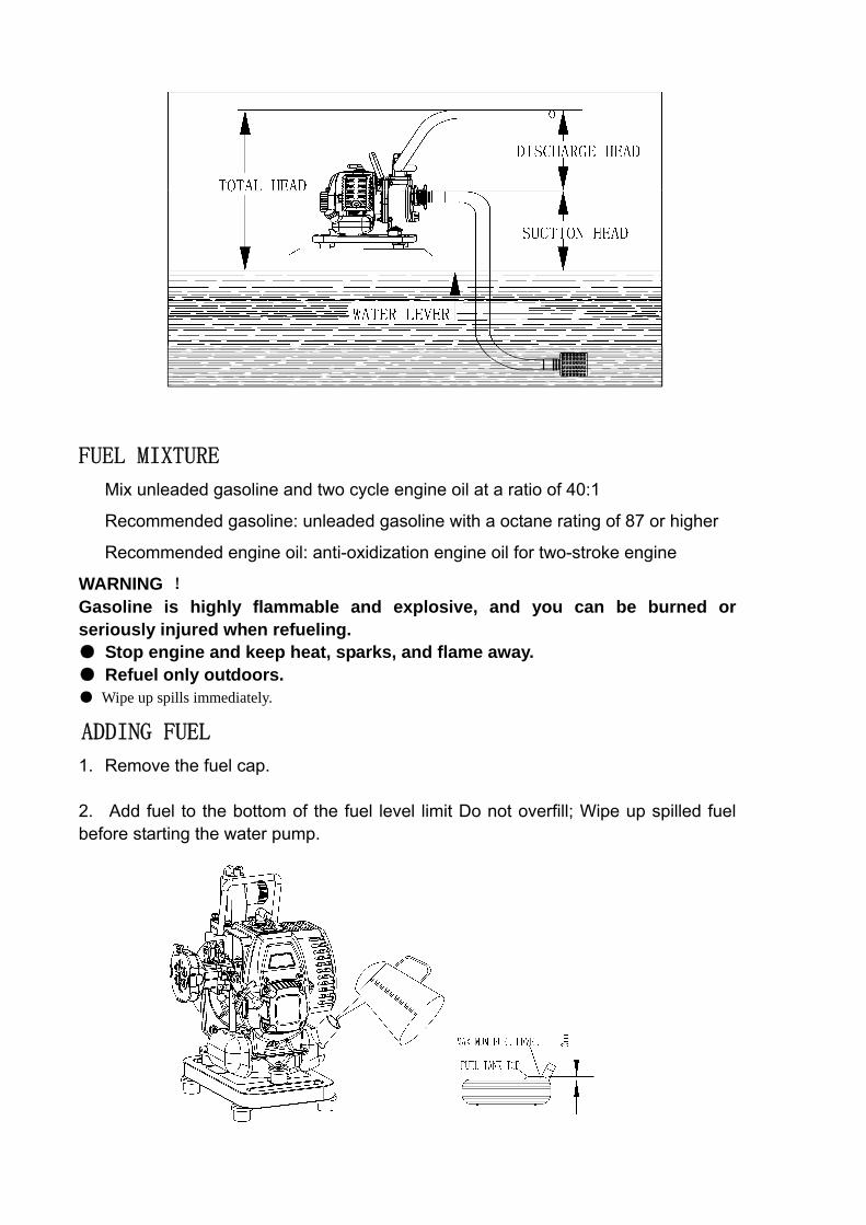
FUEL MIXTURE
Mix unleaded gasoline and two cycle engine oil at a ratio of 40:1
Recommended gasoline: unleaded gasoline with a octane rating of 87 or higher
Recommended engine oil: anti-oxidization engine oil for two-stroke engine
WARNING ! Gasoline is highly flammable and explosive, and you can be burned or seriously injured when refueling. ● Stop engine and keep heat, sparks, and flame away. ● Refuel only outdoors. ● Wipe up spills immediately.
ADDING FUEL
1. Remove the fuel cap. 2. Add fuel to the bottom of the fuel level limit Do not overfill; Wipe up spilled fuel before starting the water pump.

SUCTION HOSE INSTALLATION • Put the wing button, the hose coupler, the sealing washer together such as shown
in figure 1. • Use a hose clamp to attach the suction hose to the connector in order to prevent
air leakage and loss of suction force. Verify that the sealing washer is in good condition. (see figure 2)
• Install the strainer on the other end of the suction hose, and secure it with a hose clamp. The strainer will help to prevent the pump from being jammed or damaged by debris. (see figure 3)
• ·Securely tighten the connector on the pump suction port. (see figure 2 and 3)
DISCHARGE HOSE INSTALLATION
• It is best to use a short, large-diameter hose, because that will reduce fluid friction • and improve pump output. • Use a hose clamp to attach the discharge hose to the connector. Verify that the
sealing washer is in good condition. • Tighten the connector on the discharge port.
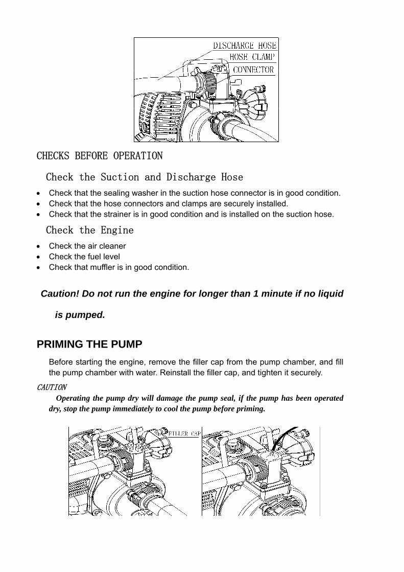
CHECKS BEFORE OPERATION
Check the Suction and Discharge Hose
• Check that the sealing washer in the suction hose connector is in good condition. • Check that the hose connectors and clamps are securely installed. • Check that the strainer is in good condition and is installed on the suction hose.
Check the Engine
• Check the air cleaner • Check the fuel level • Check that muffler is in good condition.
Caution! Do not run the engine for longer than 1 minute if no liquid
is pumped.
PRIMING THE PUMP Before starting the engine, remove the filler cap from the pump chamber, and fill the pump chamber with water. Reinstall the filler cap, and tighten it securely.
CAUTION Operating the pump dry will damage the pump seal, if the pump has been operated
dry, stop the pump immediately to cool the pump before priming.

STARTING THE ENGINE
1. To start a cold engine, move the choke lever to the CLOSE position. To restart a warm engine, leave the choke lever in the OPEN position.
2. Move the throttle lever from the SLOW position about 1/3 of the way toward
the FAST position.
3. Pinch five to six times on the priming bulb
4. Pull the starter grip lightly until you feel resistance, and then pull the starter grip up quickly.
Return the starter grip gently.
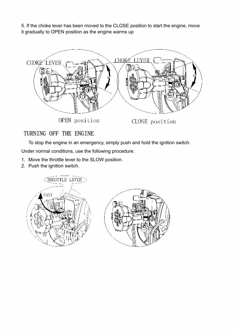
5. If the choke lever has been moved to the CLOSE position to start the engine, move it gradually to OPEN position as the engine warms up
TURNING OFF THE ENGINE
To stop the engine in an emergency, simply push and hold the ignition switch.
Under normal conditions, use the following procedure.
1. Move the throttle lever to the SLOW position. 2. Push the ignition switch.
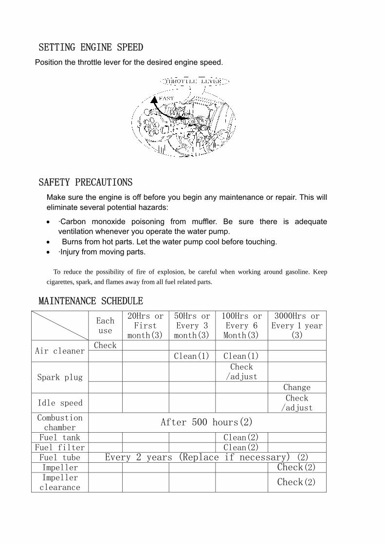
SETTING ENGINE SPEED
Position the throttle lever for the desired engine speed.
SAFETY PRECAUTIONS
Make sure the engine is off before you begin any maintenance or repair. This will eliminate several potential hazards:
• ·Carbon monoxide poisoning from muffler. Be sure there is adequate ventilation whenever you operate the water pump.
• Burns from hot parts. Let the water pump cool before touching. • ·Injury from moving parts.
To reduce the possibility of fire of explosion, be careful when working around gasoline. Keep cigarettes, spark, and flames away from all fuel related parts.
MAINTENANCE SCHEDULE
Each use
20Hrs or First
month(3)
50Hrs or Every 3 month(3)
100Hrs or Every 6 Month(3)
3000Hrs or Every 1 year
(3) Check
Air cleaner Clean(1) Clean(1)
Check
/adjust
Spark plug Change
Idle speed Check
/adjust Combustion chamber
After 500 hours(2)
Fuel tank Clean(2) Fuel filter Clean(2) Fuel tube Every 2 years (Replace if necessary) (2) Impeller Check(2) Impeller clearance
Check(2)

(1) Service more frequently when used in dusty area. (2) These items should be serviced by technicians. (3) For commercial use, log hours of operation to determine proper maintenance.
AIR CLEANER MAINTENANCE
A dirty air cleaner will restrict air flow into the carburetor. To prevent carburetor malfunction, service the air cleaner regularly. Service more frequently when operating in extremely dusty areas. WARNING Operating the engine without an air cleaner cover, or with a damaged air cleaner cover, will allow dirt to enter the engine, causing rapid engine wear. NOTICE Never run the engine without the air cleaner. Rapid engine wear will result from contaminants, such as dust and dirt being drawn into the engine. a. Unscrew the wing nut, remove the air cleaner cover and remove the foam element. b. Wash the element in solution of household detergent and warm water, then rinse thoroughly, or wash in nonflammable or high flash point solvent. Allow the element to dry thoroughly. c. Reinstall the air cleaner element and the cover.
SPARK PLUG SERVICE
In order to service the spark plug, you will need a spark plug wrench (commercially available). To ensure proper engine operation, the spark plug must be properly gapped and free of deposits. If the engine has been running, the muffler will be very hot. Be careful not to touch the muffler. a. Remove the spark plug cap by hand. b. Clean any dirt from around the spark plug base. c. Use a spark plug wrench to remove the spark plug.
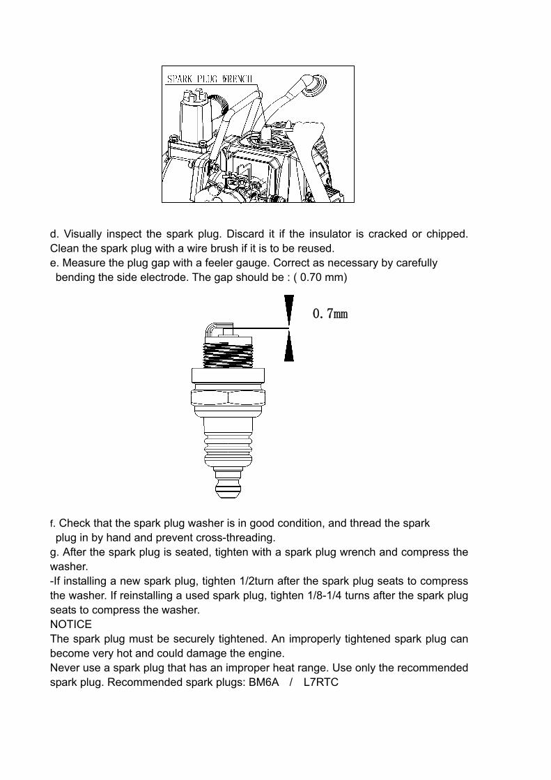
d. Visually inspect the spark plug. Discard it if the insulator is cracked or chipped. Clean the spark plug with a wire brush if it is to be reused. e. Measure the plug gap with a feeler gauge. Correct as necessary by carefully bending the side electrode. The gap should be : ( 0.70 mm)
0.7mm
f. Check that the spark plug washer is in good condition, and thread the spark plug in by hand and prevent cross-threading. g. After the spark plug is seated, tighten with a spark plug wrench and compress the washer. -If installing a new spark plug, tighten 1/2turn after the spark plug seats to compress the washer. If reinstalling a used spark plug, tighten 1/8-1/4 turns after the spark plug seats to compress the washer. NOTICE The spark plug must be securely tightened. An improperly tightened spark plug can become very hot and could damage the engine. Never use a spark plug that has an improper heat range. Use only the recommended spark plug. Recommended spark plugs: BM6A / L7RTC
8. STORAGE Proper storage preparation is essential.
CLEANING If the water pump has been running, allow it to cool for about an hour before cleaning. Clean all
exterior surfaces,
FUEL
Gasoline will oxidize and deteriorate in storage. Old gasoline will cause hard starting, and it leaves deposits that clog the fuel system.
If the gasoline in your water pump deteriorates during storage, you may need to have the carburetor and fuel system component serviced and replaced.
You can avoid fuel deterioration problems by draining the carburetor and the fuel tank or using a commercial grade fuel stabilizer.
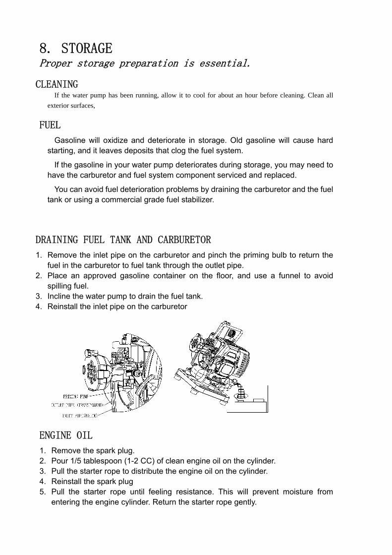
DRAINING FUEL TANK AND CARBURETOR
1. Remove the inlet pipe on the carburetor and pinch the priming bulb to return the fuel in the carburetor to fuel tank through the outlet pipe.
2. Place an approved gasoline container on the floor, and use a funnel to avoid spilling fuel.
3. Incline the water pump to drain the fuel tank. 4. Reinstall the inlet pipe on the carburetor
ENGINE OIL
1. Remove the spark plug. 2. Pour 1/5 tablespoon (1-2 CC) of clean engine oil on the cylinder. 3. Pull the starter rope to distribute the engine oil on the cylinder. 4. Reinstall the spark plug 5. Pull the starter rope until feeling resistance. This will prevent moisture from
entering the engine cylinder. Return the starter rope gently.
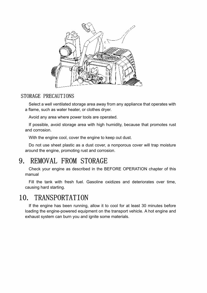
STORAGE PRECAUTIONS
Select a well ventilated storage area away from any appliance that operates with a flame, such as water heater, or clothes dryer.
Avoid any area where power tools are operated.
If possible, avoid storage area with high humidity, because that promotes rust and corrosion.
With the engine cool, cover the engine to keep out dust.
Do not use sheet plastic as a dust cover, a nonporous cover will trap moisture around the engine, promoting rust and corrosion.
9. REMOVAL FROM STORAGE
Check your engine as described in the BEFORE OPERATION chapter of this manual
Fill the tank with fresh fuel. Gasoline oxidizes and deteriorates over time, causing hard starting.
10. TRANSPORTATION
If the engine has been running, allow it to cool for at least 30 minutes before loading the engine-powered equipment on the transport vehicle. A hot engine and exhaust system can burn you and ignite some materials.
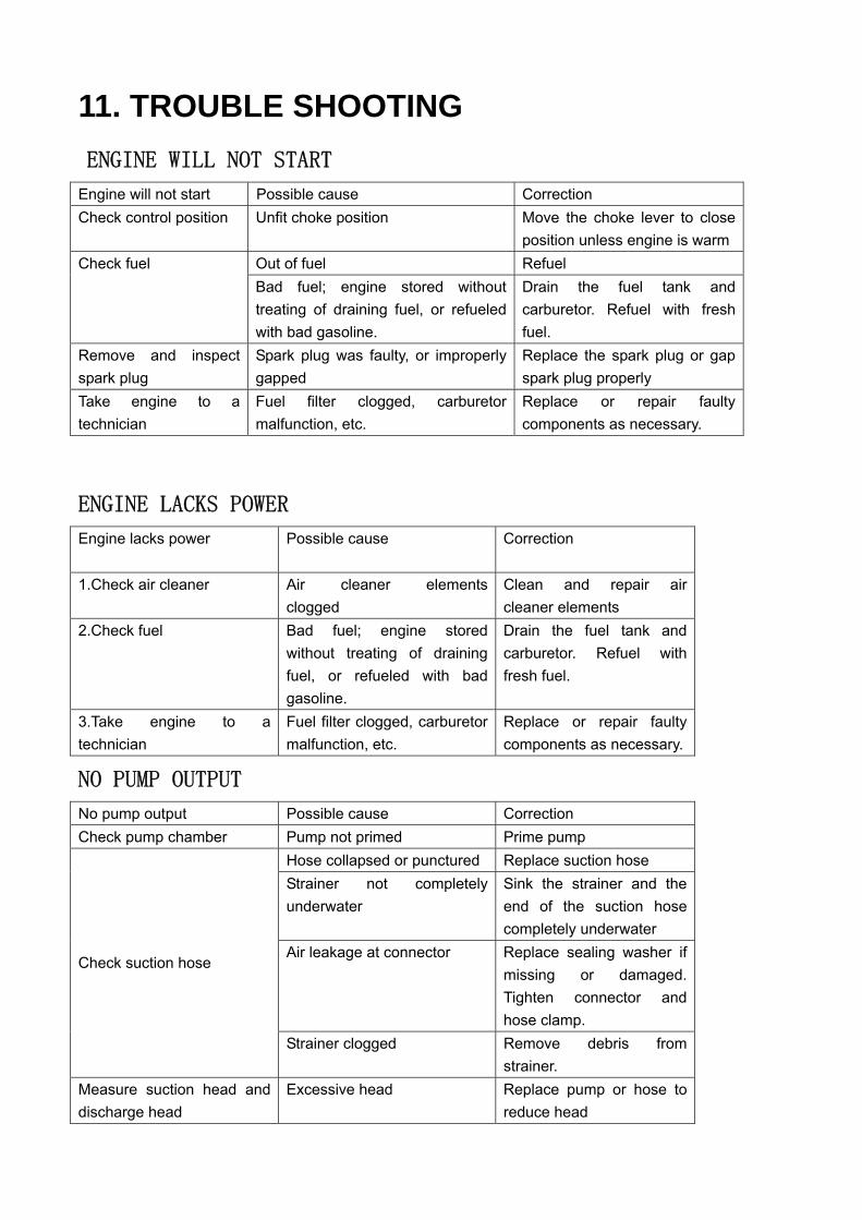
11. TROUBLE SHOOTING ENGINE WILL NOT START
Engine will not start Possible cause Correction Check control position Unfit choke position Move the choke lever to close
position unless engine is warm Out of fuel Refuel Check fuel Bad fuel; engine stored without treating of draining fuel, or refueled with bad gasoline.
Drain the fuel tank and carburetor. Refuel with fresh fuel.
Remove and inspect spark plug
Spark plug was faulty, or improperly gapped
Replace the spark plug or gap spark plug properly
Take engine to a technician
Fuel filter clogged, carburetor malfunction, etc.
Replace or repair faulty components as necessary.
ENGINE LACKS POWER
Engine lacks power
Possible cause Correction
1.Check air cleaner Air cleaner elements clogged
Clean and repair air cleaner elements
2.Check fuel Bad fuel; engine stored without treating of draining fuel, or refueled with bad gasoline.
Drain the fuel tank and carburetor. Refuel with fresh fuel.
3.Take engine to a technician
Fuel filter clogged, carburetor malfunction, etc.
Replace or repair faulty components as necessary.
NO PUMP OUTPUT
No pump output Possible cause Correction Check pump chamber Pump not primed Prime pump
Hose collapsed or punctured Replace suction hose Strainer not completely underwater
Sink the strainer and the end of the suction hose completely underwater
Air leakage at connector Replace sealing washer if missing or damaged. Tighten connector and hose clamp.
Check suction hose
Strainer clogged Remove debris from strainer.
Measure suction head and discharge head
Excessive head Replace pump or hose to reduce head
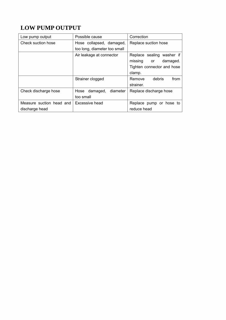
LOW PUMP OUTPUT
Low pump output Possible cause Correction Check suction hose Hose collapsed, damaged,
too long, diameter too small Replace suction hose
Air leakage at connector Replace sealing washer if missing or damaged. Tighten connector and hose clamp.
Strainer clogged Remove debris from strainer.
Check discharge hose Hose damaged, diameter too small
Replace discharge hose
Measure suction head and discharge head
Excessive head Replace pump or hose to reduce head
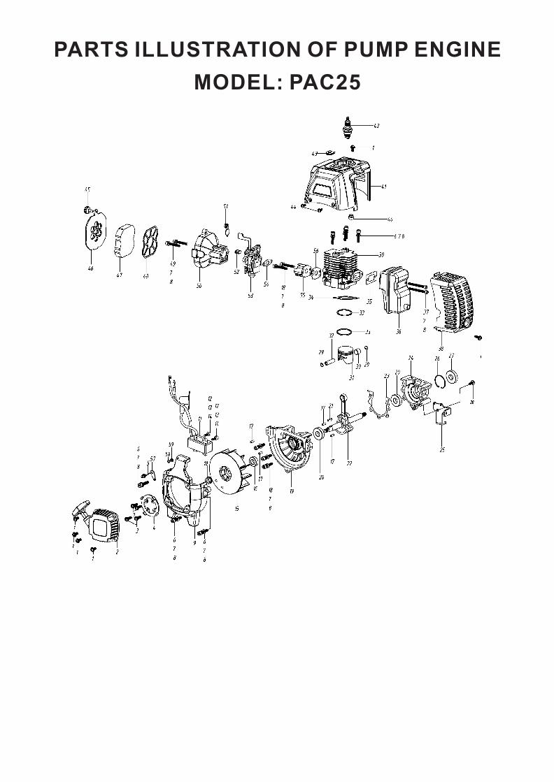
PARTS ILLUSTRATION OF PUMP ENGINE
MODEL: PAC25
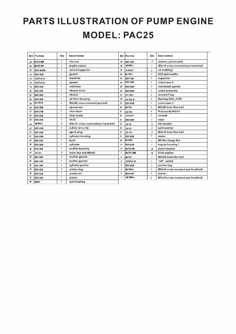
PARTS ILLUSTRATION OF PUMP ENGINE
MODEL: PAC25

PARTS ILLUSTRATION OF PUMP
MODEL: PAC25

PARTS ILLUSTRATION OF PUMP
MODEL: PAC25


![Engine Oil[1]](https://cdn.vdocuments.site/doc/165x107/577ccd1f1a28ab9e788b9106/engine-oil1.jpg)

